JP2010114768A - Video processing unit, system, and program - Google Patents
Video processing unit, system, and program Download PDFInfo
- Publication number
- JP2010114768A JP2010114768A JP2008286922A JP2008286922A JP2010114768A JP 2010114768 A JP2010114768 A JP 2010114768A JP 2008286922 A JP2008286922 A JP 2008286922A JP 2008286922 A JP2008286922 A JP 2008286922A JP 2010114768 A JP2010114768 A JP 2010114768A
- Authority
- JP
- Japan
- Prior art keywords
- dark
- projection
- video processing
- image
- projector
- Prior art date
- Legal status (The legal status is an assumption and is not a legal conclusion. Google has not performed a legal analysis and makes no representation as to the accuracy of the status listed.)
- Pending
Links
Images


Abstract
Description
本発明は、投影装置と対向するように撮像装置が設置されたビデオ会議システム等に利用して好適な映像処理装置、システム及びプログラム関する。 The present invention relates to a video processing apparatus, system, and program suitable for use in a video conference system in which an imaging apparatus is installed so as to face a projection apparatus.
近年では、ネットワークを用いて双方向映像通信を行うビデオ会議システムが製品化されている。ビデオ会議システムでは、映像を表示する装置として、CRTや液晶ディスプレイだけではなく、持ち運びが便利で大画面による表示が可能なプロジェクタが利用される。 In recent years, video conference systems that perform bidirectional video communication using a network have been commercialized. In a video conference system, not only a CRT and a liquid crystal display but also a projector that can be easily carried and can be displayed on a large screen is used as a device for displaying an image.
この種のビデオ会議システムにおいて、互いに相手の顔を見ながら視線を一致させて会議等を行うことはコミュニケーションを行う上で重要である。視線を一致させるためには、カメラを映像が表示されている場所の近くに設置する必要がある。しかしながら、映像を表示する装置にプロジェクタを使用する場合、プロジェクタの投影光がカメラに映り込んでしまい、撮影映像が見づらいものとなる問題がある。 In this type of video conference system, it is important for communication to perform a conference or the like by matching the line of sight while looking at each other's faces. In order to match the line of sight, it is necessary to install a camera near the place where the image is displayed. However, when a projector is used as a device for displaying an image, there is a problem that the projected light of the projector is reflected on the camera, making it difficult to see the captured image.
プロジェクタを用いて視線一致を実現するため、スクリーンにカメラを埋め込み、プロジェクタ投影光がカメラの視野外になる場所にプロジェクタを設置して照射する例が特許文献1に開示されている。しかしながら、この例はカメラをスクリーンに埋め込む構成により実現できるものであり、壁等の専用スクリーン以外の場所に投影する場合を考慮すると、設置の容易さや持ち運びの便利さに欠ける。
In order to realize line-of-sight matching using a projector,
また、視線を一致させるため、透過型スクリーンを用いて、プロジェクタとカメラをスクリーン後方に設置する例が特許文献2に開示されている。しかしながら、この例では、特殊なスクリーンを必要とするため、特許文献1の例と同様に設置の容易さや持ち運びの便利さに欠ける。
Further,
上述したように、映像を表示する装置としてプロジェクタを使用するビデオ会議システムにおいて、視線が一致するようにカメラを設置した場合、プロジェクタの投影光がカメラに映り込んでしまい、撮影映像が見づらいものとなる問題がある。特許文献1、2に開示されている技術では、この問題を解決することができるが、プロジェクタの設置の容易さや持ち運びの便利さが損なわれるという問題がある。
As described above, in a video conference system that uses a projector as an image display device, when the camera is installed so that the line of sight matches, the projected light of the projector is reflected on the camera, and the captured image is difficult to see. There is a problem. The techniques disclosed in
本発明は上記のような点に鑑みてなされたものであり、プロジェクタの設置の容易さや持ち運びの便利さを損なうことなく、プロジェクタの投影光がカメラに映り込んで撮影映像が見づらいものとなることを防ぐことを目的とする。 The present invention has been made in view of the above points, and the projected light of the projector is reflected on the camera without impairing the ease of installation and carrying around of the projector, making it difficult to view the captured image. The purpose is to prevent.
本発明の映像処理装置は、撮像装置に対向するように設置された投影装置に接続する映像処理装置であって、前記投影装置により投影する映像上に暗領域を設定する暗領域設定手段を備えたことを特徴とする。
本発明の映像処理システムは、投影装置と、前記投影装置と対向するように設置された撮像装置と、前記投影装置に接続する映像処理装置とを備えた映像処理システムであって、前記投影装置により投影する映像上に暗領域を設定する暗領域設定手段を備えたことを特徴とする。
本発明のプログラムは、撮像装置に対向するように設置された投影装置に接続する映像処理装置で用いられるプログラムであって、前記投影装置により投影する映像上に暗領域を設定する処理をコンピュータに実行させる。
The video processing apparatus of the present invention is a video processing apparatus that is connected to a projection apparatus installed so as to face the imaging apparatus, and includes a dark area setting unit that sets a dark area on an image projected by the projection apparatus. It is characterized by that.
The video processing system of the present invention is a video processing system comprising a projection device, an imaging device installed so as to face the projection device, and a video processing device connected to the projection device, wherein the projection device According to the present invention, there is provided dark area setting means for setting a dark area on the projected image.
The program of the present invention is a program used in a video processing apparatus connected to a projection apparatus installed so as to face an imaging apparatus, and performs processing for setting a dark region on a video projected by the projection apparatus. Let it run.
本発明によれば、投影装置により投影する映像上に暗領域を設定することにより、撮像装置への投影光の映り込みを減らすことができ、撮影映像が見づらいものとなるのを防ぐことができる。また、投影装置により投影する映像に画像処理を施すものであるので、特殊な投影装置やスクリーンを必要とせず、投影装置の設置の容易さや持ち運びの便利さが損なわれることもない。 According to the present invention, by setting a dark region on the image projected by the projection device, it is possible to reduce the reflection of the projection light on the imaging device and to prevent the captured image from being difficult to see. . Further, since image processing is performed on the image projected by the projection device, no special projection device or screen is required, and the ease of installation of the projection device and the convenience of carrying are not impaired.
以下、添付図面を参照して、本発明の好適な実施形態について説明する。各実施形態では、本発明を映像処理システムであるビデオ会議システムに適用した例について説明する。
(第1の実施形態)
図1は、本実施形態のビデオ会議システムを構成するプロジェクタとカメラの配置を示す図である。ビデオ会議システムにおいて、プロジェクタ(投影装置)1は、スクリーン3に映像を投影する。
Preferred embodiments of the present invention will be described below with reference to the accompanying drawings. In each embodiment, an example in which the present invention is applied to a video conference system that is a video processing system will be described.
(First embodiment)
FIG. 1 is a diagram showing the arrangement of projectors and cameras that constitute the video conference system of the present embodiment. In the video conference system, a projector (projection device) 1 projects an image on a screen 3.
カメラ(撮像装置)2でユーザ4を撮影する場合、図1(a)、(b)に示すように、カメラ2をユーザ4と対向するように設置、すなわち、カメラ2をプロジェクタ1と対向するように設置する必要がある。特に、自拠点のユーザ4と他拠点のユーザ5との視線を一致させるためには、図1(b)に示すように、ユーザ4の視線に近い高さにカメラ2を設置する必要がある。
When the
この状態では、プロジェクタ1の投影光がカメラ2に映り込んでしまい、図2に示すように、カメラ2の撮影映像14における輝度が飽和して、映像14が見づらいものとなる。図2は、プロジェクタ1の投影光がカメラ2に映り込んだときの撮影映像14を模式的に表した図である。撮影映像14において、プロジェクタ1の投影口12の周囲は高輝度になり、映り込み光13が発生するため、撮影映像14が見づらいものとなる。
In this state, the projection light of the
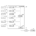
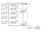
図3は、本実施形態のビデオ会議システムの構成例を示す図である。本実施形態のビデオ会議システムでは、プロジェクタ1と、カメラ2と、これらプロジェクタ1及びカメラ2に接続する映像処理装置8とを備える。相手側の対向装置21も同様の構成をとり、映像処理装置8はネットワーク7を介して対向装置21と接続し、映像や音声の送受信を行う。
FIG. 3 is a diagram illustrating a configuration example of the video conference system according to the present embodiment. The video conference system of this embodiment includes a
映像処理装置8は、音声出力部31と、音声入力部32と、表示制御部33と、操作部34と、映像出力部35と、映像入力部36と、通信部37と、全体制御部38とを備える。各部31〜37は内部バス等を介して全体制御部38と接続し、全体制御部38でそれぞれの制御を行う。
The
スピーカー41は音声出力部31と接続し、対向装置21が送信する音声を出力する。マイク42は音声入力部32と接続し、自拠点のユーザの音声を入力する。
The
ディスプレイ43は表示制御部33と接続し、映像処理装置8の操作画面等を表示する。ディスプレイ43としては、CRTや液晶ディスプレイ等の表示装置が挙げられるが、特定の表示装置に限定されない。マウス44は操作部34と接続し、ユーザの操作を入力する。もちろん、マウス44以外にも、キーボードやタッチパネル等の入力装置が接続する構成であってもよい。
The
映像出力部35はプロジェクタ1と接続し、プロジェクタ1に投影する映像を出力する。映像入力部36はカメラ2と接続し、カメラ2から撮影映像を受信する。プロジェクタ1と映像出力部35の接続形態、及び、カメラ2と映像入力部36の接続形態としては、USBやIEEE802.11等が挙げられるが、特定の接続形態に限定されるものではない。
The
通信部37はネットワーク7を介して対向装置21と接続し、映像や音声を送受信する。ネットワーク7は、インターネットに限らず、イントラネットやLAN等の様々なネットワークにより構成される。また、ネットワーク7を介して接続する対向装置21は1つに限定されない。
The
以上のようにした映像処理装置8は、例えばCPU、ROM、RAM等を具備する汎用のパーソナルコンピュータを用いて構成することが可能である。
The
次に、図4を参照して、本発明を適用した画像処理の基本原理を説明する。プロジェクタ1とスクリーン3の間にカメラ2を設置する場合に、プロジェクタ1により投影する映像に暗領域を重畳するように設定することによって、カメラ2の撮影映像への投影光の映り込みを減少させるものである。ここで、暗領域とは暗い色の領域のことであり、特定の色に限定されるものではない。
Next, the basic principle of image processing to which the present invention is applied will be described with reference to FIG. When the
図4(a)は、プロジェクタ1からスクリーン(投影位置)3を見たときの図である。スクリーン3の手前にカメラ2が設置されているため、プロジェクタ1により投影した映像51とカメラ2とが重なる。そこで、図4(b)に示すように、プロジェクタ1により投影した映像51上においてカメラ2に対応する部分、具体的にはプロジェクタ1からスクリーン3を見たときにカメラ2と重なる領域に暗領域を配置するように投影することで、投影映像51上に暗領域52を設定する。これにより、カメラ2への投影光の映り込みを減らすことできる。
FIG. 4A is a diagram when the screen (projection position) 3 is viewed from the
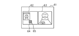
次に、図5及び図6を参照して、暗領域の設定方法について説明する。図5に示すように、ディスプレイ43に暗領域設定画面61を表示する。暗領域設定画面61において、映像62はプロジェクタ1がスクリーン3に投影する映像であり、例えば対向装置21から受信した映像が含まれる。また、映像63はカメラ2の撮像映像である。
Next, a dark region setting method will be described with reference to FIGS. As shown in FIG. 5, a dark
この暗領域設定画面61上において、カメラ2の撮影映像63を視認しながら、プロジェクタ1により投影する映像62上に暗領域64を設定することができる。このとき、カメラ2への映り込みの影響を低減するように、暗領域64の位置、大きさ等の属性をマウスポインタ65で操作し、調整する。
On the dark
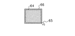
図6に示すように、暗領域64の位置及び大きさの設定は、一般的なウィンドウシステムと同様、マウスポインタ65により暗領域64の周囲に設定された操作部分66をドラッグ等の操作をすることで行う。例えば操作部分66をドラッグしながら、左右にマウスポインタ65を移動させれば暗領域64の幅を変更することができ、上下にマウスポインタ65を移動させれば暗領域64の高さを変更することができる。また、斜めにマウスポインタ65を移動させれば暗領域64の高さ及び幅を同時に変更することができる。
As shown in FIG. 6, the position and size of the
なお、ここでは暗領域64の属性として、位置、大きさを説明したが、それ以外にも形状、色、柄、濃度等を任意に設定できるようにしても良い。例えば暗領域64の形状は矩形状に限られるものではなく、円形、楕円形や四角形、五角形等であってもよく、また、あらかじめ設定された複数の形状から選択可能としてもよい。
Although the position and size have been described as the attributes of the
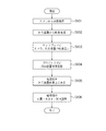
次に、図7のフローチャートを参照して、暗領域64の設定手順について説明する。図7は、暗領域64を設定するときに全体制御部38が実行するソフトウェアの処理手順である。以下の処理手順が、本発明でいう暗領域設定手段、表示制御手段の処理例となる。全体制御部38は、CPUに相当し、コンピュータ可読媒体であるROMからRAMに読み出されたプログラムを参照することにより図7の処理を実行する。
Next, the procedure for setting the
まず、ステップS101において、全体制御部38は、カメラ2から映像を取得し、ステップS102において、対向装置21から通信部37を介して映像(対向装置映像)を受信する。次に、ステップS103において、全体制御部38は、図5に示したように、ディスプレイ43に対向装置映像を含む映像62とカメラ2の撮影映像63とを同時に表示させる(暗領域設定画面)。また、ステップS104において、全体制御部38は、映像62をプロジェクタ1に投影させる。
First, in step S101, the
次に、ステップS105において、全体制御部38は、ディスプレイ43上の映像62に暗領域64を重畳して配置する。このとき、暗領域64が重畳された映像はプロジェクタ1より投影される。
Next, in step S <b> 105, the
そして、ステップS106において、全体制御部38は、図6で説明した手順により暗領域64の位置、大きさ、形状等の調整を行い、暗領域64を設定する。このとき、ディスプレイ43上のカメラ2の撮影映像63を見ながら、カメラ2への投影光の映り込みの影響が最小かどうかを目視で確認する。最小になったと判断した場合、終了する。
In step S106, the
以上の説明においては、映像処理装置8と対向装置21とをネットワーク経由で接続した構成としたが、本発明において対向装置21は必要ではない。例えば投影映像を閲覧する様子を録画するためにカメラ2を図1のように配置する場合がある。
In the above description, the
以上述べたように、第1の実施形態では、プロジェクタ1の投影光が映り込む場所にカメラ2を設置した場合、プロジェクタ1により投影する映像上に暗領域を設定することにより、カメラ2への投影光の映り込みを減少させることができる。これにより、対向装置21での表示映像(カメラ2の撮影映像を含む)が従来の暗領域の重畳がないものに比べて、見やすいものとなる。
As described above, in the first embodiment, when the
(第2の実施形態)
第2の実施形態では、プロジェクタ1と対向するように設置されたカメラ2の撮影映像における輝度ヒストグラムを使用することで、暗領域64の設定を自動的に最適化する例について説明をする。なお、ビデオ会議システム全体の構成や各機器の構成は第1の実施形態と同様である。本実施形態でも、投影する画像の制御及び作成は全体制御部38上で動作するソフトウェアにおいて行う。
(Second Embodiment)
In the second embodiment, an example will be described in which the setting of the
まず、基本的な原理について説明を行う。本実施形態では、暗領域の属性を位置及び大きさとして各々を最適化する手法を説明する。暗領域の属性は位置及び大きさに限定されるものではなく、他の属性についても同様な手法による最適化が可能である。 First, the basic principle will be described. In the present embodiment, a method for optimizing each of the attributes of the dark region using the position and size will be described. The attributes of the dark region are not limited to the position and size, and other attributes can be optimized by the same method.
第2の実施形態では、プロジェクタ1により投影する映像62上における暗領域64の位置を決定する第一段階と、暗領域64の大きさを決定する第二段階の二段階の処理を実行する。これにより、プロジェクタ1により投影した映像51上のカメラ2に対応する部分(カメラ部分)に暗領域64を設定する。
In the second embodiment, a two-stage process is executed: a first stage for determining the position of the
第一段階では、全体制御部38において作成した白色の画像上に、所定の大きさの暗領域を配置してプロジェクタ1から投影を行う。すなわち、プロジェクタ1により投影する映像上に暗領域を仮に設定する。次に、仮設定した暗領域を配置した映像をカメラ2により撮影して取得し、輝度ヒストグラムを作成する。
In the first stage, a dark area of a predetermined size is arranged on the white image created by the
そして、暗領域を再配置し、輝度ヒストグラムを作成し、画像全体に対して輝度ヒストグラムを作成するまで繰り返す。ここで、暗領域の再配置は領域を上からまた、輝度ヒストグラムを作成する度に、図8に示すように、th階級から最も高輝度な階級までの度数の和Znを記憶する。thの値の設定に関しては、判別分析法等を用いてヒストグラムの谷を発見し設定を行う。判別分析法とは、分布を分離する閾値の決定する方法である。thの値に関しては、最初に決定した値を毎回使用する。 Then, the dark regions are rearranged, a luminance histogram is created, and the process is repeated until the luminance histogram is created for the entire image. Here, the rearrangement of the dark areas stores the sum Z n of the frequencies from the th class to the highest luminance class as shown in FIG. Regarding the setting of the value of th, a valley of a histogram is found and set using a discriminant analysis method or the like. The discriminant analysis method is a method for determining a threshold for separating distributions. As for the value of th, the value determined first is used each time.
度数の和Znは、以下の式(1)により求める。式(1)において、Imaxは輝度に関するヒストグラムの階級の最大を示し、Ithはth番目の階級を示す。Hiは輝度iのヒストグラムの度数である。 The sum of frequencies Z n is obtained by the following equation (1). In Expression (1), I max indicates the maximum of the histogram class relating to luminance, and I th indicates the th th class. H i is the frequency of the histogram of luminance i.

図9(a)は度数の和Znをグラフ化したものである。図9(a)中、横軸はヒストグラムの番号を示し暗領域の位置の変化に対応する。また、縦軸は度数の和の値Zを示す。 FIG. 9A is a graph of the frequency sum Z n . In FIG. 9A, the horizontal axis indicates the histogram number and corresponds to a change in the position of the dark region. The vertical axis indicates the value Z of the frequency sum.
図9(a)において、暗領域がカメラ部分に配置されたとき、配置されてない場合に比べて、度数の和の値Zが小さくなる。このため、値Zが最小となったときの暗領域の位置を暗領域の配置場所として決定すれば、カメラ部分に対応する位置に暗領域を配置することができる。 In FIG. 9A, when the dark region is arranged in the camera portion, the sum value Z of the frequencies becomes smaller than in the case where the dark region is not arranged. For this reason, if the position of the dark region when the value Z is minimized is determined as the dark region placement location, the dark region can be placed at a position corresponding to the camera portion.
第二段階では、暗領域の大きさの調整を行う。全体制御部38において作成した白色の画像上に、前記第一段階で決定した位置に暗領域を配置してプロジェクタ1から投影を行う。次に、全体制御部38においてカメラ2の撮影映像を取得し、輝度ヒストグラムを作成する。そして、暗領域を縮小し、暗領域の縦横どちらかの長さが0になるまで輝度ヒストグラムの作成を繰り返す。また、輝度ヒストグラムを作成する度に、th階級から最も高輝度な階級までの度数の和Znを式(1)を用いて求め記憶する。ここで、thの値の設定に関しては、前記第一段階と同様である。そして、式(2)を用いて暗領域1回縮小あたりにおける部分ヒストグラムの成分和Zmの変化量brmを求める。式(2)において、Zmはm回目の式(1)による度数の和を示す。
In the second stage, the size of the dark region is adjusted. On the white image created by the
図9(b)は成分和Zmの変化量brmをグラフ化したものである。図9(b)中、横軸はループの繰り返し回数を示し、縦軸は成分和Zmの変化量の値brを示す。 FIG. 9B is a graph of the change amount br m of the component sum Z m . In FIG. 9 (b), the horizontal axis represents the number of iterations of the loop, and the vertical axis represents the value br variation component sum Z m.
暗領域がカメラ2の大きさよりも小さくなった場合、カメラ2に投影光が映り込み、撮像画像中の高輝度な点が急増するため、度数の和の値Zが大きくなる。このため、図9(b)中Zの変化量brが最大のときを暗領域の大きさとすることで、カメラ部分に対応する大きさにすることができる。
When the dark area is smaller than the size of the
以上の手順を、図10に示す全体制御部38の動作処理フローチャートに示す。暗領域の設定開始後、全体制御部38は、ステップS201において暗領域の位置の最適化を行い(第一段階)、ステップS202において暗領域の大きさの最適化を行う(第二段階)。そして、ステップS203において、全体制御部38は、暗領域の位置及び大きさをRAMに記憶し終了する。
The above procedure is shown in the operation processing flowchart of the
次に、図10(b)を参照して、ステップS201で定義した暗領域の位置の最適化手順について説明を行う。ここでは説明のため、縦横比は投影画像と同一で面積が1/s倍の黒い矩形を用いる。 Next, the procedure for optimizing the position of the dark region defined in step S201 will be described with reference to FIG. Here, for the sake of explanation, a black rectangle having the same aspect ratio as that of the projected image and an area of 1 / s times is used.
ステップS301において、全体制御部38は、白い画像上に暗領域を配置した画像をプロジェクタ1によって投影させる。ステップS302において、全体制御部38は、カメラ2の撮影映像を取得する。ステップS303において、全体制御部38は、輝度ヒストグラムを作成した後に、ステップS304において、特徴量として度数の和Znを計算し記憶する。ここで、暗領域の初期配置は白い画像上の左上端する。そして、全体制御部38は、暗領域を再配置するときは、暗領域を右に移動させ、右端まで達した場合は、左端に戻り暗領域を下に移動させる。ステップS305において、全体制御部38は、画像全体に対して暗領域を配置するまで、暗領域を再配置すると判断する。これにより、複数の映像のヒストグラムが生成されることになる。
In step S301, the
その後、ステップS306において、全体制御部38は、ステップS304で記憶した度数の和Znの比較を行い、和が最小となる暗領域の配置場所を決定し、ステップS307において、位置をメモリに記憶する。
After that, in step S306, the
次に、図10(b)を参照して、ステップS202で定義した暗領域の大きさの最適化手順について説明する。なお、ステップS201の処理とステップS202の処理を同じフローチャートを用いて説明するが、実際の処理は異なる。 Next, the procedure for optimizing the size of the dark region defined in step S202 will be described with reference to FIG. In addition, although the process of step S201 and the process of step S202 are demonstrated using the same flowchart, an actual process differs.
ステップS301において、全体制御部38は、白い画像上に暗領域を配置した画像をプロジェクタ1によって投影させる。ステップS302において、全体制御部38は、カメラ2の撮影映像を取得する。ステップS303において、全体制御部38は、輝度ヒストグラムを作成した後に、ステップS304において、度数の和Znを計算しメモリに記憶する。ここで、暗領域の初期位置及び大きさは、ステップS201で決定したものが使用され、暗領域縮小の割合は暗領域の上下左右から1ピクセルずつ縮小される。ステップS305において、全体制御部38は、暗領域の縦横どちらかの大きさが0になるまで、暗領域を再配置すると判断する。これにより、複数の映像のヒストグラムが生成されることになる。
In step S301, the
その後、ステップS306において、全体制御部38は、ステップS304で記憶した度数を用いて度数の変化量brを計算し、該変化量brが最大となる暗領域の大きさを求め、ステップS307において、大きさをメモリに記憶する。
Thereafter, in step S306, the
本実施形態では、輝度ヒストグラムを使用したが、使用するヒストグラムは輝度ヒストグラムに限定されない。例えばRGBカラーモデルの場合、RGB成分のそれぞれ、もしくは組み合わせ、もしくはすべてのヒストグラムの成分を使用することでも、暗領域の設定は可能である。 In this embodiment, the luminance histogram is used, but the histogram to be used is not limited to the luminance histogram. For example, in the case of the RGB color model, it is possible to set the dark region by using each of the RGB components, combinations, or all histogram components.
(第3の実施形態)
第3の実施形態として、図11に示すように映像処理装置8がディスプレイ43を持たない場合について説明する。本発明は、ディスプレイ43がない構成であっても効果を得ることが可能である。なお、図11に示す映像処理装置8おいて、ディスプレイ43及び表示制御部33以外の構成は図3に示した映像処理装置8と同様であり、ここではその説明を省略する。
(Third embodiment)
As a third embodiment, a case where the
ディスプレイ43を持たない映像処理装置8の場合、図5に示した自拠点のカメラ2の撮影映像63を確認する手段がない。そこで、本来の投影映像62と同時に、撮影映像63を投影映像中に配置する。そして、スクリーン3の暗領域の設定を行う。すなわち、スクリーン3を表示手段として使用するものである。
In the case of the
図12に、この場合の投影映像を示す。全体制御部38は、本来の投影映像101を表示した後に、カメラ2の撮影映像102を重畳して表示する。このとき、撮影映像102はプロジェクタ1が投影する映像101のカメラ2部分に重畳しないように配置される。そして、暗領域103をマウスカーソル104により操作し、重畳する位置、大きさ、形状等が設定される。暗領域の設定方法は、第1の実施形態と同様であるため説明を省略する。
FIG. 12 shows a projected image in this case. The
(第4の実施形態)
第4の実施形態として、プロジェクタ1による暗領域の合成について説明を行う。本発明において、投影映像に対する暗領域の配置処理や設定処理はプロジェクタ1で行うことも可能である。具体的には、映像処理装置8の操作部34より、暗領域を設定する位置を指定する。次に、暗領域を配置する位置情報と投影映像情報を個別にプロジェクタ1に伝達し、プロジェクタ1において合成処理を行った後、スクリーン3に投影する。
(Fourth embodiment)
As a fourth embodiment, composition of dark areas by the
或いは、暗領域の設定そのものをプロジェクタ1において行うようにしてもよい。すなわち、プロジェクタ1が操作部を持つ場合、プロジェクタ1において暗領域を設定する位置を指定する。次に、プロジェクタ1において映像処理装置8から伝達された投影映像上の、前記指定位置に対応した位置に暗領域を合成する。
Alternatively, the dark area setting itself may be performed in the
(第5の実施形態)
第5の実施形態として、暗領域の存在による操作性の低下を防止する方法を説明する。機器の構成及び配置に関しては、第1の実施形態もしくは第3の実施形態のどちらでも構わない。
(Fifth embodiment)
As a fifth embodiment, a method for preventing deterioration in operability due to the presence of a dark region will be described. Regarding the configuration and arrangement of the devices, either the first embodiment or the third embodiment may be used.
暗領域64をマウスポインタ65により操作し設定する場合、暗領域を領域の枠のみ、もしくは、半透明とする。これにより、設定操作中に暗領域の背景を視認可能することができる。
When the
また、暗領域を設定した後でも、マウスポインタ65等の入力装置を用いた所定の操作が行われた場合に、暗領域を枠のみ、もしくは、半透明、もしくは透明とする。これにより、暗領域を設定した後であっても、暗領域の背景を視認可能することができ、結果として操作性の低下を防止することができる。
Even after the dark area is set, if a predetermined operation using an input device such as the
なお、暗領域を枠のみ、もしくは、半透明(もしくは透明)にする方式以外にも、暗領域内を1ピクセルおきに透明にする手段や、暗領域を1秒おきに透明にする方式等もあり、特定の方式に限定されるものではない。 In addition to the method of making the dark area only a frame or semi-transparent (or transparent), there is a method for making the dark area transparent every other pixel, a method of making the dark area transparent every other second, etc. Yes, it is not limited to a specific method.
なお、本発明の目的は、上述した実施形態の機能を実現するソフトウェアのプログラムコードを記録した記憶媒体を、システム或いは装置に供給することによっても達成される。この場合、そのシステム或いは装置のコンピュータ(又はCPUやMPU)が記憶媒体に格納されたプログラムコードを読み出し実行する。 The object of the present invention can also be achieved by supplying a storage medium storing software program codes for realizing the functions of the above-described embodiments to a system or apparatus. In this case, the computer (or CPU or MPU) of the system or apparatus reads and executes the program code stored in the storage medium.
この場合、記憶媒体から読み出されたプログラムコード自体が上述した実施形態の機能を実現することになり、プログラムコード自体及びそのプログラムコードを記憶した記憶媒体は本発明を構成することになる。 In this case, the program code itself read from the storage medium realizes the functions of the above-described embodiments, and the program code itself and the storage medium storing the program code constitute the present invention.
プログラムコードを供給するための記憶媒体としては、例えば、フレキシブルディスク、ハードディスク、光ディスク、光磁気ディスク、CD−ROM、CD−R、磁気テープ、不揮発性のメモリカード、ROM等を用いることができる。 As a storage medium for supplying the program code, for example, a flexible disk, a hard disk, an optical disk, a magneto-optical disk, a CD-ROM, a CD-R, a magnetic tape, a nonvolatile memory card, a ROM, or the like can be used.
また、コンピュータが読み出したプログラムコードを実行することにより、上述した実施形態の機能が実現されるだけに限らない。例えば、そのプログラムコードの指示に基づき、コンピュータ上で稼動しているOS(基本システム或いはオペレーティングシステム)等が実際の処理の一部又は全部を行い、その処理によって上述した実施形態の機能が実現されてもよい。 Further, the functions of the above-described embodiments are not limited to being realized by executing the program code read by the computer. For example, an OS (basic system or operating system) running on the computer performs part or all of the actual processing based on an instruction of the program code, and the functions of the above-described embodiments are realized by the processing. May be.
さらに、記憶媒体から読み出されたプログラムコードが、コンピュータに挿入された機能拡張ボードやコンピュータに接続された機能拡張ユニットに備わるメモリに書き込まれる形態でもよい。この場合メモリに書き込まれた後、そのプログラムコードの指示に基づき、その機能拡張ボードや機能拡張ユニットに備わるCPU等が実際の処理の一部又は全部を行い、その処理によって上述した実施形態の機能が実現される。 Further, the program code read from the storage medium may be written in a memory provided in a function expansion board inserted into the computer or a function expansion unit connected to the computer. In this case, after being written in the memory, the CPU of the function expansion board or function expansion unit performs part or all of the actual processing based on the instruction of the program code, and the function of the above-described embodiment is performed by the processing. Is realized.
1 プロジェクタ
2 カメラ
3 スクリーン
7 ネットワーク
8 映像処理装置
31 音声出力部
32 音声入力部
33 表示制御部
34 操作部
35 映像出力部
36 映像入力部
37 通信部
38 全体制御部
41 スピーカー
42 マイク
43 ディスプレイ
44 マウス
DESCRIPTION OF
Claims (11)
前記投影装置により投影する映像上に暗領域を設定する暗領域設定手段を備えたことを特徴とする映像処理装置。 A video processing device connected to a projection device installed to face the imaging device,
An image processing apparatus comprising dark area setting means for setting a dark area on an image projected by the projection apparatus.
前記暗領域設定画面上において、前記撮像装置の撮影映像を視認しながら、前記投影装置により投影する映像上に暗領域を設定できるようにしたことを特徴とする請求項1乃至3のいずれか1項に記載の映像処理装置。 As a dark area setting means, it has a display control means for displaying on the display means a dark area setting screen for simultaneously displaying an image projected by the projection device and a captured image of the imaging device,
The dark region can be set on the image projected by the projection device while visually recognizing the image captured by the imaging device on the dark region setting screen. The video processing apparatus according to the item.
前記投影装置により投影する映像上に暗領域を合成する合成処理を前記投影装置に行わせることを特徴とする請求項1乃至7のいずれか1項に記載の映像処理装置。 Means for transmitting information of the dark area set by the dark area setting means to the projection device;
The video processing apparatus according to claim 1, wherein the projection apparatus causes the projection apparatus to perform a composition process for synthesizing a dark region on an image projected by the projection apparatus.
前記投影装置により投影する映像上に暗領域を設定する暗領域設定手段を備えたことを特徴とする映像処理システム。 A video processing system comprising a projection device, an imaging device installed to face the projection device, and a video processing device connected to the projection device,
An image processing system comprising dark region setting means for setting a dark region on an image projected by the projection device.
前記投影装置により投影する映像上に暗領域を設定する処理をコンピュータに実行させるためのプログラム。 A program used in a video processing device connected to a projection device installed to face an imaging device,
A program for causing a computer to execute processing for setting a dark region on an image projected by the projection device.
Priority Applications (1)
| Application Number | Priority Date | Filing Date | Title |
|---|---|---|---|
| JP2008286922A JP2010114768A (en) | 2008-11-07 | 2008-11-07 | Video processing unit, system, and program |
Applications Claiming Priority (1)
| Application Number | Priority Date | Filing Date | Title |
|---|---|---|---|
| JP2008286922A JP2010114768A (en) | 2008-11-07 | 2008-11-07 | Video processing unit, system, and program |
Publications (2)
| Publication Number | Publication Date |
|---|---|
| JP2010114768A true JP2010114768A (en) | 2010-05-20 |
| JP2010114768A5 JP2010114768A5 (en) | 2011-12-15 |
Family
ID=42302960
Family Applications (1)
| Application Number | Title | Priority Date | Filing Date |
|---|---|---|---|
| JP2008286922A Pending JP2010114768A (en) | 2008-11-07 | 2008-11-07 | Video processing unit, system, and program |
Country Status (1)
| Country | Link |
|---|---|
| JP (1) | JP2010114768A (en) |
Cited By (2)
| Publication number | Priority date | Publication date | Assignee | Title |
|---|---|---|---|---|
| US11019315B2 (en) | 2016-06-20 | 2021-05-25 | Panasonic Intellectual Property Management Co., Ltd. | Video display system |
| EP4181503A4 (en) * | 2020-07-08 | 2023-12-27 | Tonari KK | Virtual space connection device |
Citations (3)
| Publication number | Priority date | Publication date | Assignee | Title |
|---|---|---|---|---|
| JP2002049367A (en) * | 2000-08-04 | 2002-02-15 | Yamaha Corp | Video projecting device and video system |
| JP2006522559A (en) * | 2003-04-07 | 2006-09-28 | タンドベルク・テレコム・エイ・エス | Facilities and methods to enable eye contact between video conference participants |
| JP2007325092A (en) * | 2006-06-02 | 2007-12-13 | Sharp Corp | Video display apparatus |
-
2008
- 2008-11-07 JP JP2008286922A patent/JP2010114768A/en active Pending
Patent Citations (3)
| Publication number | Priority date | Publication date | Assignee | Title |
|---|---|---|---|---|
| JP2002049367A (en) * | 2000-08-04 | 2002-02-15 | Yamaha Corp | Video projecting device and video system |
| JP2006522559A (en) * | 2003-04-07 | 2006-09-28 | タンドベルク・テレコム・エイ・エス | Facilities and methods to enable eye contact between video conference participants |
| JP2007325092A (en) * | 2006-06-02 | 2007-12-13 | Sharp Corp | Video display apparatus |
Cited By (2)
| Publication number | Priority date | Publication date | Assignee | Title |
|---|---|---|---|---|
| US11019315B2 (en) | 2016-06-20 | 2021-05-25 | Panasonic Intellectual Property Management Co., Ltd. | Video display system |
| EP4181503A4 (en) * | 2020-07-08 | 2023-12-27 | Tonari KK | Virtual space connection device |
Similar Documents
| Publication | Publication Date | Title |
|---|---|---|
| US20160028969A1 (en) | Digital photographing apparatus and method of controlling the digital photographing apparatus | |
| US10379610B2 (en) | Information processing device and information processing method | |
| US9906762B2 (en) | Communication apparatus, method of controlling communication apparatus, non-transitory computer-readable storage medium | |
| JP6753049B2 (en) | Projector and projector control method. | |
| WO2016192325A1 (en) | Method and device for processing logo on video file | |
| KR101605771B1 (en) | Digital photographing apparatus, method for controlling the same, and recording medium storing program to execute the method | |
| JP2009094867A (en) | Information processing apparatus, remote indication system, and control program | |
| JP2009100084A (en) | Information processing apparatus, indication system, and control program | |
| JP5171560B2 (en) | Video processing apparatus, system, and program | |
| WO2011081036A1 (en) | Image processing device, image processing method, and image processing program | |
| JP2006121181A (en) | Projector apparatus, display output method, and display output program | |
| CN112272292A (en) | Projection correction method, apparatus and storage medium | |
| CN113170049B (en) | Triggering automatic image capture using scene changes | |
| US10609305B2 (en) | Electronic apparatus and operating method thereof | |
| CN108632553B (en) | Image processing device, projector, image processing method, and storage medium | |
| JP2010114768A (en) | Video processing unit, system, and program | |
| JP2010146328A (en) | Projector, and method and program for controlling the same | |
| JP2008076445A (en) | Projection-type display device, projection-type display method, program for performing this method, and computer-readable medium with the program stored | |
| KR101514346B1 (en) | Apparatus and method for making a composite photograph | |
| JP5162855B2 (en) | Image processing apparatus, remote image processing system, and image processing method | |
| KR20140130887A (en) | Method for generating thumbnail image and an electronic device thereof | |
| WO2020162051A1 (en) | Projection type video display system | |
| JP2011160062A (en) | Tracking-frame initial position setting apparatus and method of controlling operation of the same | |
| JP2014163979A (en) | Projector device, control method thereof, and control program | |
| JP2005275765A (en) | Image processor, image processing method, image processing program and recording medium recording the program |
Legal Events
| Date | Code | Title | Description |
|---|---|---|---|
| A521 | Written amendment |
Free format text: JAPANESE INTERMEDIATE CODE: A523 Effective date: 20111101 |
|
| A621 | Written request for application examination |
Free format text: JAPANESE INTERMEDIATE CODE: A621 Effective date: 20111101 |
|
| A977 | Report on retrieval |
Free format text: JAPANESE INTERMEDIATE CODE: A971007 Effective date: 20121116 |
|
| A131 | Notification of reasons for refusal |
Free format text: JAPANESE INTERMEDIATE CODE: A131 Effective date: 20121120 |
|
| A521 | Written amendment |
Free format text: JAPANESE INTERMEDIATE CODE: A523 Effective date: 20130118 |
|
| A02 | Decision of refusal |
Free format text: JAPANESE INTERMEDIATE CODE: A02 Effective date: 20130326 |