JP5166972B2 - Fuel cell system and control method thereof - Google Patents
Fuel cell system and control method thereof Download PDFInfo
- Publication number
- JP5166972B2 JP5166972B2 JP2008132008A JP2008132008A JP5166972B2 JP 5166972 B2 JP5166972 B2 JP 5166972B2 JP 2008132008 A JP2008132008 A JP 2008132008A JP 2008132008 A JP2008132008 A JP 2008132008A JP 5166972 B2 JP5166972 B2 JP 5166972B2
- Authority
- JP
- Japan
- Prior art keywords
- control valve
- refrigerant flow
- fuel cell
- refrigerant
- flow control
- Prior art date
- Legal status (The legal status is an assumption and is not a legal conclusion. Google has not performed a legal analysis and makes no representation as to the accuracy of the status listed.)
- Expired - Fee Related
Links
Images


Classifications
-
- Y—GENERAL TAGGING OF NEW TECHNOLOGICAL DEVELOPMENTS; GENERAL TAGGING OF CROSS-SECTIONAL TECHNOLOGIES SPANNING OVER SEVERAL SECTIONS OF THE IPC; TECHNICAL SUBJECTS COVERED BY FORMER USPC CROSS-REFERENCE ART COLLECTIONS [XRACs] AND DIGESTS
- Y02—TECHNOLOGIES OR APPLICATIONS FOR MITIGATION OR ADAPTATION AGAINST CLIMATE CHANGE
- Y02E—REDUCTION OF GREENHOUSE GAS [GHG] EMISSIONS, RELATED TO ENERGY GENERATION, TRANSMISSION OR DISTRIBUTION
- Y02E60/00—Enabling technologies; Technologies with a potential or indirect contribution to GHG emissions mitigation
- Y02E60/30—Hydrogen technology
- Y02E60/50—Fuel cells
Landscapes
- Fuel Cell (AREA)
Description
本発明は、燃料電池システムとその制御方法に関する。 The present invention relates to a fuel cell system and a control method thereof.
例えば燃料電池車両に備わる燃料電池システムには、燃料電池(Fuel Cell)を冷却するため、ラジエータと冷却配管を含んでなる冷却ラインが備わる。このような冷却ラインは、燃料電池を経由する冷媒を冷却配管に通流させて、燃料電池の放熱を冷媒でラジエータに運び、ラジエータで外気と熱交換して大気に放熱する。
そして、冷却ラインには冷媒を冷却配管に通流させる冷媒ポンプが備わり、冷媒ポンプを駆動することで冷媒は冷却配管を通流する。
For example, a fuel cell system provided in a fuel cell vehicle includes a cooling line including a radiator and a cooling pipe for cooling a fuel cell. In such a cooling line, the refrigerant passing through the fuel cell is caused to flow through the cooling pipe, and the heat radiation of the fuel cell is conveyed to the radiator by the refrigerant, and heat is exchanged with the outside air by the radiator to radiate the heat to the atmosphere.
The cooling line is provided with a refrigerant pump for flowing the refrigerant through the cooling pipe, and the refrigerant flows through the cooling pipe by driving the refrigerant pump.
このような冷却ラインには、燃料電池システムの始動時など燃料電池の温度が低いときに、燃料電池の冷却を停止することが要求される。例えば特許文献1には、冷媒ポンプの駆動を制御して冷媒の流量を調節し、冷却ラインにおける冷却動作を制御している。すなわち、冷媒ポンプの駆動を停止して冷媒の通流を止めることで、燃料電池の冷却を停止できる。 Such a cooling line is required to stop the cooling of the fuel cell when the temperature of the fuel cell is low, such as when the fuel cell system is started. For example, Patent Literature 1 controls the cooling operation in the cooling line by controlling the driving of the refrigerant pump to adjust the flow rate of the refrigerant. That is, the cooling of the fuel cell can be stopped by stopping the driving of the refrigerant pump and stopping the flow of the refrigerant.
しかしながら、燃料電池システムの小型化のため、燃料電池に空気を供給するコンプレッサを駆動するポンプ駆動装置(例えばモータ)で駆動する冷媒ポンプが組み込まれた燃料電池システムがあり、この場合、冷媒ポンプはコンプレッサと一体に駆動する。
そして、コンプレッサは、燃料電池システムの動作中は常時駆動することから、冷媒ポンプは、燃料電池システムの動作中は常時駆動することになる。このため、例えば特許文献1に開示される技術を適用して冷媒ポンプの駆動を制御することができず、冷媒の流量を調節することができない。
このため、冷却配管に冷媒流量制御弁を備え、冷媒流量制御弁の開度を調節して、冷却配管における冷媒の流量を調節するように構成される。
However, in order to reduce the size of the fuel cell system, there is a fuel cell system in which a refrigerant pump that is driven by a pump driving device (for example, a motor) that drives a compressor that supplies air to the fuel cell is incorporated. Drives integrally with the compressor.
Since the compressor is always driven during the operation of the fuel cell system, the refrigerant pump is always driven during the operation of the fuel cell system. For this reason, for example, the technique disclosed in Patent Document 1 cannot be applied to control the driving of the refrigerant pump, and the flow rate of the refrigerant cannot be adjusted.
Therefore, the cooling pipe is provided with a refrigerant flow control valve, and the opening of the refrigerant flow control valve is adjusted to adjust the refrigerant flow rate in the cooling pipe.
冷媒流量制御弁は、例えば制御装置で開度が調節されるバタフライ弁で、冷媒流量制御弁の開度は開度センサで検出されて制御装置に入力されるように構成される。
そして制御装置は、開度センサから入力される冷媒流量制御弁の開度に基づいて、冷媒流量制御弁を所定の開度に保つようにフィードバック制御している。
The control device performs feedback control so as to keep the refrigerant flow control valve at a predetermined opening based on the opening of the refrigerant flow control valve input from the opening sensor.
しかしながら、開度センサに検出誤差が発生した場合、制御装置は、冷媒流量制御弁の正確な開度を取得することができず、冷媒流量制御弁の開度の調節に誤差が発生し、冷却配管における冷媒の流量を精度よく調節できなくなるという問題がある。
また、冷媒流量制御弁を全開状態に維持する場合にも、冷媒流量制御弁には電力が供給されて開度が制御されていることから、冷媒流量制御弁における消費電力が大きいという問題がある。
However, when a detection error occurs in the opening sensor, the control device cannot acquire the exact opening of the refrigerant flow control valve, and an error occurs in the adjustment of the opening of the refrigerant flow control valve, and the cooling There is a problem that the flow rate of the refrigerant in the pipe cannot be adjusted with high accuracy.
In addition, even when the refrigerant flow control valve is maintained in a fully opened state, power is supplied to the refrigerant flow control valve and the opening degree is controlled, so that there is a problem that power consumption in the refrigerant flow control valve is large. .
そこで、本発明は、冷媒流量制御弁における消費電力を抑制できるとともに、冷媒流量制御弁に備わる開度センサの検出誤差を吸収して、冷媒の流量を精度よく調節できる冷媒流量制御弁を備える燃料電池システムとその制御方法を提供することを課題とする。 Therefore, the present invention can suppress power consumption in the refrigerant flow control valve, and absorbs a detection error of an opening sensor provided in the refrigerant flow control valve, thereby providing a fuel having a refrigerant flow control valve capable of accurately adjusting the refrigerant flow rate. It is an object to provide a battery system and a control method thereof.
前記課題を解決するため、本発明は、燃料電池スタックと、前記燃料電池スタックに空気を供給するコンプレッサと、前記燃料電池スタックを経由して冷却配管を通流する冷媒の流量を調節する冷媒流量制御弁と、前記冷媒流量制御弁の開度を検出する開度検出手段と、前記冷媒を前記冷却配管に通流させる冷媒ポンプと、前記冷媒流量制御弁の開度を調節する制御装置と、を備え、前記コンプレッサと前記冷媒ポンプとが、1つのポンプ駆動装置を共有し一体となって駆動する燃料電池システムとした。そして、前記制御装置は、当該燃料電池システムの始動直後に、前記冷媒流量制御弁を全閉状態にし、全閉状態における前記開度検出手段の検出値を第1基準値として取得し、前記第1基準値に基づいて、前記冷媒流量制御弁の開度を調節することを特徴とした。 In order to solve the above problems, the present invention provides a fuel cell stack, a compressor for supplying air to the fuel cell stack, and a refrigerant flow rate for adjusting a flow rate of a refrigerant flowing through a cooling pipe via the fuel cell stack. A control valve, an opening degree detecting means for detecting an opening degree of the refrigerant flow rate control valve, a refrigerant pump for passing the refrigerant through the cooling pipe, and a control device for adjusting the opening degree of the refrigerant flow rate control valve; The fuel cell system is configured such that the compressor and the refrigerant pump share one pump driving device and are driven integrally. Then, immediately after the fuel cell system is started, the control device fully closes the refrigerant flow control valve, acquires the detection value of the opening degree detection means in the fully closed state as a first reference value, and The opening degree of the refrigerant flow control valve is adjusted based on one reference value.
この発明によると、制御装置は、燃料電池システムの始動直後に、冷媒流量制御弁を全閉状態にして、全閉状態のときの開度検出手段の検出値である第1基準値を取得して、第1基準値に基づいて冷媒流量制御弁の開度を調節できる。この構成によって、開度検出手段に検出誤差が発生した場合であっても、開度検出手段の検出誤差を含んだ第1基準値に基づいて冷媒流量制御弁の開度を調節できることから、開度検出手段の検出誤差を好適に吸収して精度よく冷媒流量制御弁の開度を調節できる。 According to this invention, immediately after the start of the fuel cell system, the control device sets the refrigerant flow rate control valve to a fully closed state, and obtains a first reference value that is a detection value of the opening degree detection means in the fully closed state. Thus, the opening degree of the refrigerant flow control valve can be adjusted based on the first reference value. With this configuration, even when a detection error occurs in the opening detection means, the opening of the refrigerant flow control valve can be adjusted based on the first reference value including the detection error of the opening detection means. The detection error of the degree detection means is suitably absorbed, and the opening degree of the refrigerant flow control valve can be adjusted with high accuracy.
また、本発明は、前記制御装置は、前記冷媒流量制御弁を全閉状態にして前記第1基準値を取得し、前記冷媒流量制御弁を全開状態にして、全開状態における前記開度検出手段の検出値を第2基準値として取得し、前記第1基準値及び前記第2基準値に基づいて、前記冷媒流量制御弁の開度を調節することを特徴とした。 Further, according to the present invention, the control device sets the refrigerant flow rate control valve to a fully closed state, acquires the first reference value, sets the refrigerant flow rate control valve to a fully open state, and opens the opening degree detection means in the fully open state. The detected value is acquired as a second reference value, and the opening of the refrigerant flow control valve is adjusted based on the first reference value and the second reference value.
この発明によると、制御装置は、第1基準値を取得し、さらに、冷媒流量制御弁を全開状態にして、全開状態のときの開度検出手段の検出値である第2基準値を取得して、第1基準値と第2基準値に基づいて冷媒流量制御弁の開度を調節できる。この構成によって、開度検出手段に検出誤差が発生した場合であっても、開度検出手段の検出誤差を含んだ第1基準値と第2基準値に基づいて冷媒流量制御弁の開度を調節できることから、開度検出手段の検出誤差を好適に吸収して精度よく冷媒流量制御弁の開度を調節できる。 According to this invention, the control device acquires the first reference value, further sets the refrigerant flow control valve to the fully open state, and acquires the second reference value that is the detection value of the opening degree detection means when in the fully open state. Thus, the opening degree of the refrigerant flow control valve can be adjusted based on the first reference value and the second reference value. With this configuration, even when a detection error occurs in the opening degree detection means, the opening degree of the refrigerant flow control valve is adjusted based on the first reference value and the second reference value including the detection error of the opening degree detection means. Since it can be adjusted, the detection error of the opening degree detecting means is suitably absorbed, and the opening degree of the refrigerant flow control valve can be adjusted with high accuracy.
また、本発明は、前記制御装置は、予め設定された前記冷媒流量制御弁の開度と前記開度検出手段の検出値との相関関係を、前記第1基準値に基づいて補正し、補正された前記相関関係に基づいて、前記冷媒流量制御弁の開度を調節することを特徴とした。 Further, according to the present invention, the control device corrects a correlation between a preset opening degree of the refrigerant flow control valve and a detection value of the opening degree detection means based on the first reference value, and On the basis of the correlation, the opening degree of the refrigerant flow rate control valve is adjusted.
この発明によると、予め設定されている冷媒流量制御弁の開度と開度検出手段の検出値の相関関係を、第1基準値で補正することができる。したがって、開度と検出値の相関関係を、開度検出手段の検出誤差を含んだものに補正することができる。そして、補正された開度と検出値の相関関係に基づいて冷媒流量制御弁の開度を調節できることから、開度検出手段の検出誤差を好適に吸収でき、精度よく冷媒流量制御弁の開度を調節できる。 According to the present invention, the correlation between the opening degree of the refrigerant flow rate control valve and the detection value of the opening degree detection means that are set in advance can be corrected with the first reference value. Therefore, the correlation between the opening degree and the detected value can be corrected to include the detection error of the opening degree detecting means. Since the opening degree of the refrigerant flow control valve can be adjusted based on the correlation between the corrected opening degree and the detected value, the detection error of the opening degree detecting means can be suitably absorbed, and the opening degree of the refrigerant flow control valve can be accurately obtained. Can be adjusted.
また、本発明は、前記冷媒流量制御弁は、弁体駆動手段の駆動で動作する弁体と、前記制御装置からの指令に基づいて、前記弁体駆動手段に電力を供給する電力供給手段と、当該冷媒流量制御弁が全開状態になるように前記弁体を付勢する付勢手段と、を含み、前記制御装置は、前記冷媒流量制御弁を全開状態にする冷媒流量制御弁未使用モードを検出するモード検出手段を備えるとともに、前記モード検出手段が、前記冷媒流量制御弁未使用モードを検出した場合、前記制御装置は、前記第1基準値及び前記第2基準値を取得した後に、前記弁体駆動手段への電力の供給を停止するように前記電力供給手段に指令を与え、前記冷媒流量制御弁を全開状態にすることを特徴とした。 Further, according to the present invention, the refrigerant flow control valve includes a valve element that operates by driving the valve element driving unit, and a power supply unit that supplies electric power to the valve element driving unit based on a command from the control device. And an urging means for urging the valve body so that the refrigerant flow rate control valve is in a fully opened state, and the control device is a refrigerant flow rate control valve unused mode for making the refrigerant flow rate control valve in a fully opened state. And when the mode detection unit detects the refrigerant flow rate control valve unused mode, the control device acquires the first reference value and the second reference value, A command is given to the power supply means to stop the supply of power to the valve body driving means, and the refrigerant flow control valve is fully opened.
この発明によると、冷媒流量制御弁を全開状態にする冷媒流量制御弁未使用モードをモード検出手段が検出した場合、制御装置は、第1基準値及び第2基準値を取得した後、電力供給手段に指令を与えて、弁体駆動手段への電力の供給を停止することができる。したがって、冷媒流量制御弁未使用モードの時は、冷媒流量制御弁に電力を供給することがなく、電力の消費を抑制できる。 According to the present invention, when the mode detecting means detects the refrigerant flow control valve unused mode in which the refrigerant flow control valve is fully opened, the control device acquires the first reference value and the second reference value, and then supplies power. A command can be given to the means to stop the supply of electric power to the valve body driving means. Therefore, in the refrigerant flow control valve unused mode, power consumption can be suppressed without supplying power to the refrigerant flow control valve.
また、本発明は、前記制御装置は、前記モード検出手段が前記冷媒流量制御弁未使用モードを検出した場合であっても、前記燃料電池システムの始動直後に、前記冷媒流量制御弁を全閉状態にして、前記第1基準値を取得し、前記冷媒流量制御弁を全開状態にして、前記第2基準値を取得することを特徴とした。 Further, according to the present invention, the control device fully closes the refrigerant flow control valve immediately after the fuel cell system is started, even when the mode detection unit detects the refrigerant flow control valve unused mode. The first reference value is acquired in a state, the refrigerant flow rate control valve is fully opened, and the second reference value is acquired.
この発明によると、モード検出手段による冷媒流量制御弁未使用モードの検出の有無にかかわらず、制御装置は、燃料電池システムの始動直後に、第1基準値及び第2基準値を取得することができる。したがって、開度検出手段の検出誤差を好適に吸収して精度よく冷媒流量制御弁の開度を調節できる。 According to the present invention, the control device can acquire the first reference value and the second reference value immediately after the start of the fuel cell system, regardless of whether or not the refrigerant flow rate control valve unused mode is detected by the mode detecting means. it can. Therefore, it is possible to adjust the opening of the refrigerant flow control valve with high accuracy by suitably absorbing the detection error of the opening detection means.
また、本発明は、前記制御装置は、前記燃料電池システムの始動直後の、前記ポンプ駆動装置が動作していないときに、前記第1基準値を取得することを特徴とした。 In addition, the present invention is characterized in that the control device acquires the first reference value when the pump drive device is not operating immediately after the fuel cell system is started.
この発明によると、制御装置が第1基準値を取得するために冷媒流量制御弁を全閉状態にしても、冷媒が冷却配管を通流していないことから、冷媒の通流を遮断することによる影響がない。 According to the present invention, the refrigerant is not flowing through the cooling pipe even when the refrigerant flow control valve is fully closed so that the control device acquires the first reference value. There is no effect.
また、本発明は、燃料電池スタックと、前記燃料電池スタックに空気を供給するコンプレッサと、前記燃料電池スタックを経由して冷却配管を通流する冷媒の流量を調節する冷媒流量制御弁と、前記冷媒流量制御弁の開度を検出する開度検出手段と、前記冷媒を前記冷却配管に通流させる冷媒ポンプと、前記冷媒流量制御弁の開度を調節する制御装置と、を備え、前記コンプレッサと前記冷媒ポンプは、1つのポンプ駆動装置を共有し一体となって駆動し、前記冷媒流量制御弁は、弁体駆動手段の駆動で動作する弁体と、前記制御装置からの指令に基づいて、前記弁体駆動手段に電力を供給する電力供給手段と、当該冷媒流量制御弁が全開状態になるように前記弁体を付勢する付勢手段と、を含んでなる燃料電池システムの制御方法とした。そして、当該燃料電池システムの始動直後に、前記制御装置が、前記冷媒流量制御弁を全閉状態にするステップと、前記冷媒流量制御弁が全閉状態のときに、前記開度検出手段が検出する検出値を、前記制御装置が第1基準値として取得するステップと、前記制御装置が、前記冷媒流量制御弁を全開状態にするステップと、を有することを特徴とした。 The present invention also includes a fuel cell stack, a compressor for supplying air to the fuel cell stack, a refrigerant flow rate control valve for adjusting a flow rate of a refrigerant flowing through a cooling pipe via the fuel cell stack, An opening degree detecting means for detecting an opening degree of the refrigerant flow control valve, a refrigerant pump for passing the refrigerant through the cooling pipe, and a control device for adjusting the opening degree of the refrigerant flow rate control valve. And the refrigerant pump share one pump driving device and are driven integrally, the refrigerant flow rate control valve is based on a valve body that operates by driving valve body driving means, and a command from the control device A control method for a fuel cell system, comprising: power supply means for supplying electric power to the valve body drive means; and urging means for urging the valve body so that the refrigerant flow rate control valve is fully opened. It was. Then, immediately after the fuel cell system is started, the control device detects the opening degree detecting means when the refrigerant flow rate control valve is fully closed and the refrigerant flow rate control valve is fully closed. The control device has a step of acquiring the detected value as a first reference value, and the control device has a step of fully opening the refrigerant flow rate control valve.
この発明によると、燃料電池システムの始動直後に、制御装置が冷媒流量制御弁を全閉状態にするステップと、冷媒流量制御弁が全閉状態のときに、開度検出手段が検出する検出値を、制御装置が第1基準値として取得するステップと、制御装置が冷媒流量制御弁を全開状態にするステップと、で燃料電池システムを制御し、制御装置は、第1基準値を取得できる。 According to the present invention, immediately after starting the fuel cell system, the control device sets the refrigerant flow control valve to the fully closed state, and the detection value detected by the opening degree detection means when the refrigerant flow control valve is in the fully closed state. The control device acquires the first reference value, and the control device fully opens the refrigerant flow control valve, and the control device can acquire the first reference value.
本発明によれば、冷媒流量制御弁における消費電力を抑制できるとともに、冷媒流量制御弁に備わる開度センサの検出誤差を吸収して、冷媒の流量を精度よく調節できる冷媒流量制御弁を備える燃料電池システムとその制御方法を提供することができる。 ADVANTAGE OF THE INVENTION According to this invention, the fuel provided with the refrigerant | coolant flow control valve which can suppress the power consumption in a refrigerant | coolant flow control valve, can absorb the detection error of the opening degree sensor with which a refrigerant | coolant flow control valve is equipped, and can adjust the flow volume of a refrigerant | coolant accurately. A battery system and a control method thereof can be provided.
以下、本発明を実施するための最良の形態について、適宜図を参照して詳細に説明する。
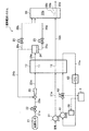
図1は、本実施形態に係る燃料電池システムの構成を示す図である。図1に示す本実施形態に係る燃料電池システム1は、図示しない燃料電池車両(移動体)に搭載されている。燃料電池システム1は、燃料電池スタック10と、燃料電池スタック10のアノードに対して水素(燃料ガス、反応ガス)を給排するアノード系と、燃料電池スタック10のカソードに対して酸素を含む空気(酸化剤ガス、反応ガス)を給排するカソード系と、燃料電池スタック10を経由する冷媒を冷却する冷却ラインと、を備えている。
さらに、燃料電池システム1を制御する制御装置3が備わる。
Hereinafter, the best mode for carrying out the present invention will be described in detail with reference to the drawings as appropriate.
FIG. 1 is a diagram showing a configuration of a fuel cell system according to the present embodiment. A fuel cell system 1 according to this embodiment shown in FIG. 1 is mounted on a fuel cell vehicle (moving body) (not shown). The fuel cell system 1 includes a fuel cell stack 10, an anode system that supplies and discharges hydrogen (fuel gas and reaction gas) to and from the anode of the fuel cell stack 10, and air that contains oxygen with respect to the cathode of the fuel cell stack 10. A cathode system for supplying and discharging (oxidant gas, reaction gas) and a cooling line for cooling the refrigerant passing through the fuel cell stack 10;
Furthermore, the control apparatus 3 which controls the fuel cell system 1 is provided.
制御装置3は、例えば図示しないCPU(Central Processing Unit)、RAM(Random Access Memory)、ROM(Read Only Memory)などを備えるコンピュータおよびプログラム、周辺回路などを含んで構成され、ROMに記憶されるプログラムによって制御される。
そして、冷却ラインに備わる冷媒流量制御弁62の開度の調節、アノード系に備わるコンプレッサ31と冷却ラインに備わる冷媒ポンプ61を駆動するモータ(ポンプ駆動装置)65の駆動制御を含み、燃料電池システム1全体を制御する機能を有する。
The control device 3 includes, for example, a computer and a program including a CPU (Central Processing Unit), a RAM (Random Access Memory), a ROM (Read Only Memory), and the like (not shown), peripheral circuits, etc., and a program stored in the ROM Controlled by.
The fuel cell system includes adjustment of the opening degree of the refrigerant flow control valve 62 provided in the cooling line, drive control of the compressor 31 provided in the anode system and a motor (pump driving device) 65 that drives the refrigerant pump 61 provided in the cooling line. 1 has the function of controlling the whole.
<燃料電池スタック>
燃料電池スタック10は、複数(例えば200〜400枚)の固体高分子型の単セルが積層されることで構成されたスタックであり、複数の単セルは電気的に直列で接続されている。単セルは、MEA(Membrane Electrode Assembly:膜電極接合体)と、これを挟み2枚の導電性を有するアノードセパレータおよびカソードセパレータと、を備えている。
<Fuel cell stack>
The fuel cell stack 10 is a stack formed by stacking a plurality of (for example, 200 to 400) solid polymer type single cells, and the plurality of single cells are electrically connected in series. The single cell includes an MEA (Membrane Electrode Assembly) and two conductive anode separators and cathode separators sandwiching the MEA.
MEAは、1価の陽イオン交換膜(例えばパーフルオロスルホン酸型)からなる電解質膜(固体高分子膜)と、これを挟むアノードおよびカソードとを備えている。アノードおよびカソードは、カーボンペーパ等の導電性を有する多孔質体から主に構成されると共に、アノードおよびカソードにおける電極反応を生じさせるための触媒(Pt、Ru等)を含んでいる。 The MEA includes an electrolyte membrane (solid polymer membrane) made of a monovalent cation exchange membrane (for example, perfluorosulfonic acid type), and an anode and a cathode sandwiching the electrolyte membrane. The anode and the cathode are mainly composed of a conductive porous material such as carbon paper, and contain a catalyst (Pt, Ru, etc.) for causing an electrode reaction in the anode and the cathode.
アノードセパレータには、各MEAのアノードに対して水素を給排するため単セルの積層方向に延びる貫通孔(内部マニホールドと称される)や、単セルの面方向に延びる溝が形成されており、これら貫通孔および溝がアノード流路11(燃料ガス流路)として機能している。
カソードセパレータには、各MEAのカソードに対して空気を給排するため単セルの積層方向に延びる貫通孔(内部マニホールドと称される)や、単セルの面方向に延びる溝が形成されており、これら貫通孔および溝がカソード流路12(酸化剤ガス流路)として機能している。
The anode separator is formed with a through-hole (called an internal manifold) extending in the stacking direction of the single cells and a groove extending in the surface direction of the single cells in order to supply and discharge hydrogen to the anode of each MEA. These through holes and grooves function as the anode flow path 11 (fuel gas flow path).
The cathode separator is formed with a through-hole (referred to as an internal manifold) extending in the stacking direction of the single cells and a groove extending in the surface direction of the single cells in order to supply and discharge air to and from the cathode of each MEA. These through holes and grooves function as the cathode channel 12 (oxidant gas channel).
このようなアノード流路11を介して各アノードに水素が供給されると、後記式(1)の電極反応が起こり、また、カソード流路12を介して各カソードに空気が供給されると、後記式(2)の電極反応が起こり、各単セルで電位差(OCV(Open Circuit Voltage)、開回路電圧)が発生するようになっている。そして、燃料電池スタック10と走行モータ等の外部回路とが電気的に接続されて電流が取り出されると、燃料電池スタック10が発電するようになっている。
2H2→4H++4e− …(1)
O2+4H++4e−→2H2O …(2)
When hydrogen is supplied to each anode via the anode channel 11, an electrode reaction of the following formula (1) occurs, and when air is supplied to each cathode via the cathode channel 12, An electrode reaction of the following formula (2) occurs, and a potential difference (OCV (Open Circuit Voltage), open circuit voltage) is generated in each single cell. When the fuel cell stack 10 and an external circuit such as a travel motor are electrically connected and current is taken out, the fuel cell stack 10 generates power.
2H 2 → 4H + + 4e − (1)
O 2 + 4H + + 4e − → 2H 2 O (2)
このようにして燃料電池スタック10が発電すると、カソードで生成した水(水蒸気)の一部は、電解質膜を透過し、アノードに移動する。したがって、カソードから排出されるカソードオフガス、およびアノードから排出されるアノードオフガスは、いずれも多湿となる。 When the fuel cell stack 10 generates power in this way, a part of the water (water vapor) generated at the cathode permeates the electrolyte membrane and moves to the anode. Therefore, both the cathode offgas discharged from the cathode and the anode offgas discharged from the anode are humid.
<アノード系>
アノード系は、燃料電池スタック10よりも上流側に備えられる、水素タンク21、常閉型の遮断弁22、エゼクタ23、および燃料電池スタック10よりも下流側に備えられる、気液分離器24、常閉型のパージ弁26を備えている。
<Anode system>
The anode system is provided upstream of the fuel cell stack 10, the hydrogen tank 21, the normally closed shut-off valve 22, the ejector 23, and the gas-liquid separator 24 provided downstream of the fuel cell stack 10, A normally closed purge valve 26 is provided.
水素タンク21は、配管21a、遮断弁22、配管22a、エゼクタ23、および配管23aを介して、アノード流路11の入口側に接続されている。配管22aには、水素を所定圧力に減圧する減圧弁(不図示)が設けられており、この減圧弁には、カソード流路12に向かう空気の圧力が信号圧(パイロット圧)として入力されており、減圧弁は、前記空気の圧力とアノード流路11における水素の圧力とが極間差圧を守るように制御するようになっている。
そして、燃料電池車両のイグニッションがONされ、燃料電池スタック10の起動が要求されたときに遮断弁22が開かれると、水素タンク21の水素が配管21a等を介してアノード流路11に供給されるようになっている。
The hydrogen tank 21 is connected to the inlet side of the anode channel 11 through a pipe 21a, a shutoff valve 22, a pipe 22a, an ejector 23, and a pipe 23a. The piping 22a is provided with a pressure reducing valve (not shown) for reducing hydrogen to a predetermined pressure, and the pressure of air toward the cathode flow path 12 is input to the pressure reducing valve as a signal pressure (pilot pressure). The pressure reducing valve controls the pressure of the air and the pressure of hydrogen in the anode channel 11 so as to keep the differential pressure between the electrodes.
Then, when the ignition of the fuel cell vehicle is turned on and the shutoff valve 22 is opened when the start of the fuel cell stack 10 is requested, hydrogen in the hydrogen tank 21 is supplied to the anode flow path 11 via the pipe 21a and the like. It has become so.
アノード流路11の出口は、配管24a、気液分離器24、配管24bを介して、エゼクタ23の吸込口に接続されている。そして、アノード流路11(アノード)から排出された未反応の水素を含むアノードオフガスは、気液分離器24において、これに同伴する液状の水分が分離された後、燃料電池スタック10の上流側のエゼクタ23に戻されるようになっている。
そして、エゼクタ23に戻されたアノードオフガスは、水素タンク21からの水素と混合された後、アノード流路11に再供給されるようになっている。つまり、本実施形態では、配管24aおよび配管24bによって、水素を循環させて再利用する水素循環ラインが構成されている。
なお、配管24bの気液分離器24側に近い部分は、鉛直方向で配置されており、水素に同伴する水分が含まれているときに、これが自重により気液分離器24に戻されるようになっている。
The outlet of the anode channel 11 is connected to the suction port of the ejector 23 via a pipe 24a, a gas-liquid separator 24, and a pipe 24b. The anode off gas containing unreacted hydrogen discharged from the anode channel 11 (anode) is separated from the liquid water accompanying the anode off gas in the gas-liquid separator 24, and then upstream of the fuel cell stack 10. Is returned to the ejector 23.
The anode off-gas returned to the ejector 23 is mixed with hydrogen from the hydrogen tank 21 and then re-supplied to the anode channel 11. That is, in this embodiment, the hydrogen circulation line which circulates and recycles hydrogen is comprised by the piping 24a and the piping 24b.
In addition, the part close to the gas-liquid separator 24 side of the pipe 24b is arranged in the vertical direction so that when moisture accompanying hydrogen is contained, it is returned to the gas-liquid separator 24 by its own weight. It has become.
一方、気液分離器24で分離された水分は、一時的に気液分離器24内に貯留された後、配管25a、制御装置3により適宜に開かれる常閉型のドレン弁25、配管25bを通じて、後記する希釈器33の上部側に排出されるようになっている。 On the other hand, the water separated by the gas-liquid separator 24 is temporarily stored in the gas-liquid separator 24, and then the pipe 25a and the normally closed drain valve 25 and the pipe 25b that are appropriately opened by the control device 3. And is discharged to the upper side of a diluter 33 to be described later.
パージ弁26は、常閉型の電磁弁であり、燃料電池スタック10の発電時において、配管24aおよび配管24bを循環するアノードオフガス(水素)に含まれる不純物(水蒸気、窒素等)を排出(パージ)する場合に、制御装置3によって開かれる弁である。パージ弁26の上流側は、配管26aを介して配管24bに接続され、下流側は、配管26bを介して、後記する希釈器33の上部側に接続されている。
ここで、制御装置3は、例えば、燃料電池スタック10を構成する単セルの電圧(セル電圧)が所定セル電圧以下となった場合、不純物を排出する必要があると判定し、パージ弁26を開くように設定されている。セル電圧は、例えば、単セルの電圧を検出する電圧センサ(セル電圧モニタ)を介して検出され、制御装置3に入力される。
The purge valve 26 is a normally closed solenoid valve that discharges impurities (water vapor, nitrogen, etc.) contained in the anode off-gas (hydrogen) circulating through the pipe 24a and the pipe 24b when the fuel cell stack 10 generates power (purge). ) Is a valve opened by the control device 3. The upstream side of the purge valve 26 is connected to the pipe 24b via the pipe 26a, and the downstream side is connected to the upper side of the diluter 33 described later via the pipe 26b.
Here, for example, when the voltage (cell voltage) of the single cells constituting the fuel cell stack 10 is equal to or lower than a predetermined cell voltage, the control device 3 determines that the impurities need to be discharged, and sets the purge valve 26 It is set to open. The cell voltage is detected, for example, via a voltage sensor (cell voltage monitor) that detects the voltage of a single cell, and is input to the control device 3.
<カソード系>
カソード系は、コンプレッサ31と、希釈器33と、図示しない加湿器と、を備えている。
<Cathode system>
The cathode system includes a compressor 31, a diluter 33, and a humidifier (not shown).
コンプレッサ31は、配管31a、図示しない加湿器を介して、カソード流路12の入口に接続されている。そして、制御装置3の指令にしたがって作動すると、コンプレッサ31は、酸素を含む空気を取り込み、空気をカソード流路12に供給するようになっている。また、コンプレッサ31は、燃料電池スタック10の掃気時には、これを掃気する掃気手段として機能するようになっている。
なお、コンプレッサ31は、燃料電池スタック10及び/又は燃料電池スタック10の発電電力を充放電する、図示しない高圧バッテリを電源とするモータ65によって作動される。
The compressor 31 is connected to the inlet of the cathode channel 12 via a pipe 31a and a humidifier (not shown). When operated according to a command from the control device 3, the compressor 31 takes in oxygen-containing air and supplies the air to the cathode channel 12. The compressor 31 functions as a scavenging means for scavenging the fuel cell stack 10 when scavenging.
The compressor 31 is operated by a motor 65 that uses a high-voltage battery (not shown) as a power source for charging and discharging the fuel cell stack 10 and / or the power generated by the fuel cell stack 10.
カソード流路12の出口は、配管32b、図示しない加湿器を介して、希釈器33に接続されている。そして、カソード流路12(カソード)から排出された多湿のカソードオフガスは、配管32b等を介して、希釈器33に供給されるようになっている。なお、配管32bには、カソード流路12における空気の圧力を制御する図示しない背圧弁(バタフライ弁等)が設けられている。 The outlet of the cathode channel 12 is connected to the diluter 33 via a pipe 32b and a humidifier (not shown). The humid cathode off gas discharged from the cathode channel 12 (cathode) is supplied to the diluter 33 through the pipe 32b and the like. The pipe 32b is provided with a back pressure valve (not shown) such as a butterfly valve that controls the air pressure in the cathode flow path 12.
図示しない加湿器は、コンプレッサ31からカソード流路12に向かう空気を加湿するため、カソード流路12に向かう空気と、多湿のカソードオフガスとを水分交換させる中空糸膜を備えている。 A humidifier (not shown) includes a hollow fiber membrane for exchanging moisture between the air traveling from the compressor 31 toward the cathode flow path 12 and the air flowing toward the cathode flow path 12 and the humid cathode offgas.
<希釈器>
希釈器33は、パージ弁26から導入されるアノードオフガスと、配管32bから導入されるカソードオフガス(希釈用ガス)とを混合し、アノードオフガス中の水素を、カソードオフガスで希釈する容器であり、その内部に希釈空間33aを備えている。具体的には、希釈器33は、希釈空間33aの鉛直下方に、カソードオフガスが流れる配管33bを有しており、配管33bには、その内部と希釈空間33aとを連通させる連通孔33cが形成されている。
<Diluter>
The diluter 33 is a container that mixes the anode off-gas introduced from the purge valve 26 and the cathode off-gas (dilution gas) introduced from the pipe 32b to dilute hydrogen in the anode off-gas with the cathode off-gas, A dilution space 33a is provided therein. Specifically, the diluter 33 has a pipe 33b through which the cathode off gas flows vertically below the dilution space 33a. The pipe 33b has a communication hole 33c that communicates the inside with the dilution space 33a. Has been.
配管33bを通流するカソードオフガスは、連通孔33cを介して、希釈空間33aに滞留するアノードオフガスを吸引し、配管33bの内部でカソードオフガスとアノードオフガスの混合ガスを生成する。このように、カソードオフガスとアノードオフガスの混合ガスを生成することで、アノードオフガス中の水素を希釈し、水素濃度を低減する。そして、生成した混合ガスは、配管33dを介して車外に排出されるようになっている。 The cathode off gas flowing through the pipe 33b sucks the anode off gas staying in the dilution space 33a through the communication hole 33c, and generates a mixed gas of the cathode off gas and the anode off gas inside the pipe 33b. In this way, by generating a mixed gas of the cathode offgas and the anode offgas, hydrogen in the anode offgas is diluted and the hydrogen concentration is reduced. And the produced | generated mixed gas is discharged | emitted outside the vehicle through the piping 33d.
<冷却ライン>
さらに、燃料電池システム1には、燃料電池スタック10を経由する冷媒を冷却する冷却ラインが備わる。冷却ラインは、燃料電池スタック10とラジエータ63との間を冷媒が循環可能に、冷却配管63aで接続した系であり、冷媒を循環させる冷媒ポンプ61を備える。
ラジエータ63は、燃料電池スタック10の放熱を、冷却配管63aを通流する冷媒を介して外気と熱交換して大気に放出する機能を有する。
冷媒は、例えば冷却水である。
<Cooling line>
Further, the fuel cell system 1 is provided with a cooling line for cooling the refrigerant passing through the fuel cell stack 10. The cooling line is a system connected by a cooling pipe 63a so that the refrigerant can circulate between the fuel cell stack 10 and the radiator 63, and includes a refrigerant pump 61 that circulates the refrigerant.
The radiator 63 has a function of releasing heat of the fuel cell stack 10 to the atmosphere through heat exchange with the outside air via a refrigerant flowing through the cooling pipe 63a.
The refrigerant is, for example, cooling water.
冷媒ポンプ61は、冷媒を加圧して冷却配管63aに通流させ、冷却ラインに冷媒を循環させる。さらに、冷却配管63aには、冷媒の流量を調節する冷媒流量制御弁62が備わる。
冷却配管63aに冷媒を通流させる冷媒ポンプ61は、例えば、モータ65によって駆動されるが、燃料電池システム1を小型化するため、燃料電池スタック10に空気を供給するコンプレッサ31を駆動するモータ65によって、冷媒ポンプ61をコンプレッサ31と一体に駆動させる場合がある。
The refrigerant pump 61 pressurizes the refrigerant to flow through the cooling pipe 63a, and circulates the refrigerant through the cooling line. Further, the cooling pipe 63a is provided with a refrigerant flow rate control valve 62 for adjusting the flow rate of the refrigerant.
The refrigerant pump 61 that causes the refrigerant to flow through the cooling pipe 63a is driven by, for example, a motor 65. To reduce the size of the fuel cell system 1, the motor 65 that drives the compressor 31 that supplies air to the fuel cell stack 10 is used. Therefore, the refrigerant pump 61 may be driven integrally with the compressor 31.
このような場合、コンプレッサ31が駆動している間は、冷媒ポンプ61の出力を単独で制御できないことから、冷却配管63aにおける冷媒の流量を調節できない。そこで、冷却配管63aに冷媒流量制御弁62を備える。冷媒流量制御弁62は、弁体によって開度が調節され、その開度によって冷却配管63aを通流する冷媒の流量を調節する。 In such a case, while the compressor 31 is being driven, the output of the refrigerant pump 61 cannot be controlled independently, so that the flow rate of the refrigerant in the cooling pipe 63a cannot be adjusted. Therefore, the refrigerant flow control valve 62 is provided in the cooling pipe 63a. The opening degree of the refrigerant flow rate control valve 62 is adjusted by the valve body, and the flow rate of the refrigerant flowing through the cooling pipe 63a is adjusted by the opening degree.
<冷媒流量制御弁>
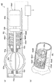
図2の(a)は、冷媒流量制御弁の構造を示す断面図、(b)は、可動板の構成を示す図である。図2の(a)に示すように、本実施形態に係る冷媒流量制御弁62は、断面が略円形の冷却配管63aの、断面中心を通って横架される回転軸62aと一体に回転するバルブ(弁体)62bによって開度が調節され、冷却配管63aを通流する冷媒の流量を調節する。
<Refrigerant flow control valve>
2A is a cross-sectional view showing the structure of the refrigerant flow control valve, and FIG. 2B is a view showing the configuration of the movable plate. As shown in FIG. 2A, the refrigerant flow rate control valve 62 according to the present embodiment rotates integrally with a rotary shaft 62a horizontally mounted through the center of the cross section of the cooling pipe 63a having a substantially circular cross section. The opening degree is adjusted by a valve (valve element) 62b, and the flow rate of the refrigerant flowing through the cooling pipe 63a is adjusted.
バルブ62bは、玉軸受けなどの軸受け62cによって、冷媒流量制御弁62の本体62jに回転可能に支持される回転軸62aに固定され、冷却配管63aにおける冷媒の通流方向(以下、流路方向と称する)に対して垂直方向に回動する。
さらに、冷却配管63aと軸受け62cの間には、例えばオイルシール62gが備わり、冷却配管63aを通流する冷媒の、軸受け62cの側への漏洩を封じている。
なお、軸受け62cと反対の側の回転軸62aの端部は、例えば樹脂軸受け62fなどで回転自在に、冷媒流量制御弁62の本体62jに支持されるように構成すればよい。
The valve 62b is fixed to a rotating shaft 62a that is rotatably supported by the main body 62j of the refrigerant flow control valve 62 by a bearing 62c such as a ball bearing, and the refrigerant flowing direction (hereinafter referred to as a flow path direction) in the cooling pipe 63a. To the vertical direction.
Further, for example, an oil seal 62g is provided between the cooling pipe 63a and the bearing 62c, and seals the leakage of the refrigerant flowing through the cooling pipe 63a toward the bearing 62c.
In addition, what is necessary is just to comprise so that the edge part of the rotating shaft 62a on the opposite side to the bearing 62c may be rotatably supported by the main body 62j of the refrigerant | coolant flow control valve 62, for example by the resin bearing 62f.
バルブ62bの平面形状は冷却配管63aの断面形状と略等しく、バルブ62bは、冷却配管63aを通流する冷媒を全く通流させないか、ほとんど通流させない状態となる全閉位置から、冷媒を最大限に通流させる状態となる全開位置の間で開閉動作する。
全閉位置では、バルブ62bが冷却配管63aの流路方向に対して略垂直に起立して、冷却配管63aを通流する冷媒の流れを遮断し、冷媒流量制御弁62の開度が全閉である全閉状態にする。また、全開位置では、バルブ62bが冷却配管63aの流路方向に略水平になることで冷媒を最大限に通流させ、冷媒流量制御弁62の開度が全開である全開状態にする。そして、バルブ62bの冷却配管63aの流路方向に対する回転角度によって、冷媒流量制御弁62の開度が決定される。
The planar shape of the valve 62b is substantially equal to the cross-sectional shape of the cooling pipe 63a, and the valve 62b maximizes the refrigerant from the fully closed position where the refrigerant flowing through the cooling pipe 63a is not allowed to flow at all or hardly flows. It opens and closes between the fully open positions where the flow is limited.
In the fully closed position, the valve 62b stands substantially perpendicular to the flow direction of the cooling pipe 63a to block the flow of the refrigerant flowing through the cooling pipe 63a, and the opening of the refrigerant flow control valve 62 is fully closed. To the fully closed state. Further, at the fully open position, the valve 62b is substantially horizontal in the flow path direction of the cooling pipe 63a, thereby allowing the refrigerant to flow to the maximum extent, so that the opening degree of the refrigerant flow control valve 62 is fully opened. And the opening degree of the refrigerant | coolant flow control valve 62 is determined by the rotation angle with respect to the flow path direction of the cooling piping 63a of the valve 62b.
回転軸62aの、例えば軸受け62c側の端部には、開度センサ(開度検出手段)62hとDCモータ62eが取り付けられ、回転軸62aはDCモータ62eの回転駆動によって回転(動作)する。
回転軸62aにはバルブ62bが固定されることから、バルブ62bはDCモータ62eで動作することになる。したがって、DCモータ62eは請求項に記載の弁体駆動手段となる。
An opening sensor (opening detection means) 62h and a DC motor 62e are attached to the end of the rotating shaft 62a on the bearing 62c side, for example, and the rotating shaft 62a rotates (operates) by the rotational drive of the DC motor 62e.
Since the valve 62b is fixed to the rotating shaft 62a, the valve 62b is operated by the DC motor 62e. Therefore, the DC motor 62e serves as the valve body driving means described in the claims.
また、開度センサ62hは限定されるものではなく、例えば、回転軸62aの回転角度を検出する角度センサを用いることができる。
そして開度センサ62hは、回転軸62aの回転角度を検出し、検出値を電気信号などの角度信号に変換して制御装置3に入力する。
制御装置3は、開度センサ62hから入力される角度信号に基づいて、冷媒流量制御弁62の開度を取得できる。
Further, the opening sensor 62h is not limited, and for example, an angle sensor that detects the rotation angle of the rotating shaft 62a can be used.
The opening sensor 62h detects the rotation angle of the rotating shaft 62a, converts the detected value into an angle signal such as an electric signal, and inputs the angle signal to the control device 3.
The control device 3 can acquire the opening degree of the refrigerant flow control valve 62 based on the angle signal input from the opening degree sensor 62h.
DCモータ62eは、例えばモータ駆動部(電力供給手段)62e1から供給される電力で駆動し、モータ駆動部62e1は、制御装置3から入力される指令に基づいて、DCモータ62eに電力を供給してDCモータ62eを駆動する。
さらにモータ駆動部62e1は、制御装置3から入力される指令に基づいて、DCモータ62eへの電力の供給を停止する機能を有する。
The DC motor 62e is driven by power supplied from, for example, a motor drive unit (power supply unit) 62e1, and the motor drive unit 62e1 supplies power to the DC motor 62e based on a command input from the control device 3. Then, the DC motor 62e is driven.
Furthermore, the motor drive unit 62e1 has a function of stopping the supply of power to the DC motor 62e based on a command input from the control device 3.
DCモータ62eの出力軸はバルブ62bの回転軸62aと直結し、図示しないネジなどで連結されている。または、図示しない減速機構を介してDCモータ62eと回転軸62aを連結する構成であってもよい。
そして、軸受け62cとDCモータ62eとの間には、例えばコイルばねからなるリターンスプリング(付勢手段)62d1と補助スプリング62d2が、それぞれの中心軸が回転軸62aと一致するように配設されている。
The output shaft of the DC motor 62e is directly connected to the rotating shaft 62a of the valve 62b and is connected by a screw or the like (not shown). Or the structure which connects the DC motor 62e and the rotating shaft 62a via the deceleration mechanism which is not shown in figure may be sufficient.
Between the bearing 62c and the DC motor 62e, a return spring (biasing means) 62d1 and an auxiliary spring 62d2 made of, for example, a coil spring are disposed so that their central axes coincide with the rotation shaft 62a. Yes.
軸受け62cとDCモータ62eの略中間点には、回転軸62aと一体に回転する略円板状の可動板62a1が備わり、この可動板62a1にはリターンスプリング62d1の一端が係止される。
また、リターンスプリング62d1の他端は、冷媒流量制御弁62の本体62jに係止される。
A substantially disc-shaped movable plate 62a1 that rotates integrally with the rotary shaft 62a is provided at a substantially intermediate point between the bearing 62c and the DC motor 62e, and one end of a return spring 62d1 is locked to the movable plate 62a1.
The other end of the return spring 62d1 is locked to the main body 62j of the refrigerant flow control valve 62.
リターンスプリング62d1は、可動板62a1を回転軸62aの回りに回転させ、可動板62a1と、回転軸62aを介して一体に回転するバルブ62bが、冷却配管63aを開く方向(以下、弁開方向と称する)に付勢する。 The return spring 62d1 rotates the movable plate 62a1 around the rotation shaft 62a, and the movable plate 62a1 and the valve 62b that rotates together via the rotation shaft 62a open the cooling pipe 63a (hereinafter referred to as the valve opening direction). Energize).
リターンスプリング62d1と、可動板62a1を挟んで配設される補助スプリング62d2の一端は可動板62a1に係止され、補助スプリング62d2の他端は、冷媒流量制御弁62の本体62jに係止される。
補助スプリング62d2は、可動板62a1を回転軸62aの回りに回転させ、可動板62a1と、回転軸62aを介して一体に回転するバルブ62bが、冷却配管63aを閉じる方向(以下、弁閉方向と称する)に付勢する。
One end of the return spring 62d1 and the auxiliary spring 62d2 disposed across the movable plate 62a1 is locked to the movable plate 62a1, and the other end of the auxiliary spring 62d2 is locked to the main body 62j of the refrigerant flow control valve 62. .
The auxiliary spring 62d2 rotates the movable plate 62a1 around the rotation shaft 62a, and the movable plate 62a1 and the valve 62b that rotates integrally via the rotation shaft 62a close the cooling pipe 63a (hereinafter referred to as the valve closing direction). Energize).
このように、リターンスプリング62d1と補助スプリング62d2で可動板62a1を介して付勢されるバルブ62bは、リターンスプリング62d1の付勢力によって弁開方向に回転すると、補助スプリング62d2が縮径し、バルブ62bを弁閉方向に付勢する付勢力が増大する。そして、バルブ62bを弁開方向に回転するリターンスプリング62d1の付勢力と、バルブ62bを弁閉方向に付勢する補助スプリング62d2の付勢力とが釣り合った状態でバルブ62bは停止する。
そして、本実施形態に係る冷媒流量制御弁62は、リターンスプリング62d1の付勢力と補助スプリング62d2の付勢力とが釣り合ったとき、全開状態になるように設定される。
Thus, when the valve 62b urged by the return spring 62d1 and the auxiliary spring 62d2 via the movable plate 62a1 rotates in the valve opening direction by the urging force of the return spring 62d1, the auxiliary spring 62d2 is reduced in diameter, and the valve 62b The urging force that urges the valve in the valve closing direction increases. Then, the valve 62b stops in a state where the urging force of the return spring 62d1 that rotates the valve 62b in the valve opening direction and the urging force of the auxiliary spring 62d2 that biases the valve 62b in the valve closing direction are balanced.
And the refrigerant | coolant flow control valve 62 which concerns on this embodiment is set so that it may be in a fully open state, when the urging | biasing force of the return spring 62d1 and the urging | biasing force of the auxiliary spring 62d2 balance.
図2の(b)に示すように、可動板62a1には、周囲の一部が外側に突出した回転止め62a4が形成され、例えば冷媒流量制御弁62の本体62jから、可動板62a1の側に突出するストッパ62a5と係合する。
可動板62a1の回転止め62a4とストッパ62a5は、バルブ62bが弁閉方向に回転し、全閉位置になるときに係合するように配置される。すなわち、可動板62a1の回転止め62a4とストッパ62a5が係合したとき、バルブ62bは全閉位置にあり、冷媒流量制御弁62は全閉状態になる。
As shown in FIG. 2 (b), the movable plate 62a1 is formed with a rotation stop 62a4 with a part of the periphery protruding outward. For example, from the main body 62j of the refrigerant flow control valve 62 to the movable plate 62a1 side. Engages with the protruding stopper 62a5.
The rotation stop 62a4 and the stopper 62a5 of the movable plate 62a1 are arranged so as to engage when the valve 62b rotates in the valve closing direction and reaches the fully closed position. That is, when the rotation stop 62a4 and the stopper 62a5 of the movable plate 62a1 are engaged, the valve 62b is in the fully closed position, and the refrigerant flow control valve 62 is fully closed.
このような構成の冷媒流量制御弁62を全閉状態にするときは、バルブ62b(図2の(a)参照)が弁閉方向に回転するように、DCモータ62e(図2の(a)参照)で回転軸62aを回転する。すなわち、制御装置3(図2の(a)参照)が、モータ駆動部62e1(図2の(a)参照)に指令を与え、モータ駆動部62e1から供給される電力でDCモータ62eを駆動する。 When the refrigerant flow control valve 62 having such a configuration is fully closed, the DC motor 62e (FIG. 2 (a)) is set so that the valve 62b (see FIG. 2 (a)) rotates in the valve closing direction. Rotate the rotating shaft 62a. That is, the control device 3 (see FIG. 2A) gives a command to the motor drive unit 62e1 (see FIG. 2A), and drives the DC motor 62e with electric power supplied from the motor drive unit 62e1. .
そして、DCモータ62eの駆動で回転する回転軸62aと一体に回転する可動板62a1の回転止め62a4がストッパ62a5に係合すると、可動板62a1の回転が係止され、可動板62a1と回転軸62aを介して一体に回転するバルブ62bが全閉位置になり、冷媒流量制御弁62が全閉状態になる。 When the rotation stop 62a4 of the movable plate 62a1 that rotates integrally with the rotary shaft 62a that rotates by driving of the DC motor 62e engages with the stopper 62a5, the rotation of the movable plate 62a1 is locked, and the movable plate 62a1 and the rotary shaft 62a. The valve 62b that rotates integrally through the valve is in the fully closed position, and the refrigerant flow control valve 62 is in the fully closed state.
冷媒流量制御弁62が全閉状態のときに、DCモータ62eへの電力の供給を停止するように、制御装置3がモータ駆動部62e1に指令を与えると、モータ駆動部62e1からDCモータ62eへの電力の供給が停止され、DCモータ62eから回転軸62aに入力されるトルクが消失する。
そして、可動板62a1はリターンスプリング62d1の付勢力で回転し、バルブ62bが弁開方向に回転する。バルブ62bは、リターンスプリング62d1の付勢力と補助スプリング62d2の付勢力が釣り合う状態に維持される。この状態における開度を、冷媒流量制御弁62の標準の開度、すなわち、デフォルト開度とする。
前記したように、本実施形態に係る冷媒流量制御弁62は、リターンスプリング62d1の付勢力と補助スプリング62d2の付勢力が釣り合う状態のとき全開状態になるように構成されることから、冷媒流量制御弁62がデフォルト開度に設定されると、冷媒流量制御弁62は全開状態になる。
このように、冷媒流量制御弁62は、DCモータ62eへの電力の供給が停止された時に設定されるデフォルト開度が全開状態であることから、冷媒流量制御弁62は、ノーマルオープンタイプの弁になる。
When the control device 3 gives a command to the motor drive unit 62e1 to stop the supply of electric power to the DC motor 62e when the refrigerant flow control valve 62 is in the fully closed state, the motor drive unit 62e1 to the DC motor 62e. Is stopped, and the torque input from the DC motor 62e to the rotating shaft 62a disappears.
The movable plate 62a1 is rotated by the urging force of the return spring 62d1, and the valve 62b is rotated in the valve opening direction. The valve 62b is maintained in a state where the urging force of the return spring 62d1 and the urging force of the auxiliary spring 62d2 are balanced. The opening in this state is the standard opening of the refrigerant flow control valve 62, that is, the default opening.
As described above, the refrigerant flow control valve 62 according to the present embodiment is configured to be fully opened when the urging force of the return spring 62d1 and the urging force of the auxiliary spring 62d2 are balanced. When the valve 62 is set to the default opening, the refrigerant flow control valve 62 is fully opened.
Thus, the refrigerant flow control valve 62 is a normally open type valve because the default opening set when the supply of power to the DC motor 62e is stopped is fully open. become.
以上のように構成される冷媒流量制御弁62(図1参照)は、制御装置3(図1参照)がモータ駆動部62e1を介してDCモータ62eの回転を制御し、開度が調節される。 In the refrigerant flow control valve 62 (see FIG. 1) configured as described above, the control device 3 (see FIG. 1) controls the rotation of the DC motor 62e via the motor drive unit 62e1, and the opening degree is adjusted. .
図2の(a)に示すように、冷媒流量制御弁62には、バルブ62bと一体に回転する回転軸62aの回転角度を検出する開度センサ62hが備わり、回転軸62aの回転角度を角度信号として制御装置3に入力する。したがって、制御装置3は、入力される回転軸62aの回転角度に基づいて、冷媒流量制御弁62の開度を取得することができ、この開度に基づいて、冷媒流量制御弁62の開度を調節できる。
そして、制御装置3は、冷媒流量制御弁62の実際の開度が、所望する開度になるように、モータ駆動部62e1を介してDCモータ62eの回転を制御して、バルブ62bを動作する。
なお、所望する開度とは、外気温や燃料電池システム1(図1参照)の各部の温度に基づいて制御装置3が算出する、冷却配管63aにおける冷媒の好適な通流量を実現するための冷媒流量制御弁62の開度である。
As shown in FIG. 2A, the refrigerant flow rate control valve 62 is provided with an opening degree sensor 62h that detects the rotation angle of the rotation shaft 62a that rotates integrally with the valve 62b, and the rotation angle of the rotation shaft 62a is set to an angle. The signal is input to the control device 3 as a signal. Therefore, the control device 3 can acquire the opening degree of the refrigerant flow rate control valve 62 based on the input rotation angle of the rotary shaft 62a, and based on this opening degree, the opening degree of the refrigerant flow rate control valve 62 is obtained. Can be adjusted.
And the control apparatus 3 controls rotation of the DC motor 62e via the motor drive part 62e1, and operates valve | bulb 62b so that the actual opening degree of the refrigerant | coolant flow control valve 62 may turn into a desired opening degree. .
The desired opening degree is for realizing a suitable refrigerant flow rate in the cooling pipe 63a calculated by the control device 3 based on the outside air temperature and the temperature of each part of the fuel cell system 1 (see FIG. 1). This is the opening degree of the refrigerant flow control valve 62.
このように、制御装置3は、開度センサ62hから入力される角度信号に基づいて、冷媒流量制御弁62の開度を調節している。しかしながら、開度センサ62hに検出誤差がある場合、制御装置3は正確な回転軸62aの回転角度を検出することができず、結果として制御装置3は、冷媒流量制御弁62の開度を正確に調節できない。
特に、個々の開度センサ62hが有する個別誤差は、設計時に除去できないため、仮に個別誤差が大きいと、開度センサ62hの検出値には、常に大きな検出誤差が生じてしまうことになる。
また、例えば冷媒流量制御弁62を商品として出荷する際に、個々の開度センサ62hの個別誤差を補正しても、冷媒流量制御弁62の運用中の温度や湿度の変化、振動などによって開度センサ62hに検出誤差が発生し、さらに、その検出誤差が蓄積されて、検出誤差が大きくなる場合がある。以降、個別誤差には、冷媒流量制御弁62の運用中に生じる誤差も含まれるものとする。
そこで、開度センサ62hの個別誤差によって生じる検出誤差を吸収するため、本実施形態に係る制御装置3は、バルブ62bが基準状態にあるときの開度センサ62hの検出値を基準値として取得する操作を実行し、この基準値に基づいて冷媒流量制御弁62の開度を調節する。
As described above, the control device 3 adjusts the opening degree of the refrigerant flow control valve 62 based on the angle signal input from the opening degree sensor 62h. However, when there is a detection error in the opening sensor 62h, the control device 3 cannot accurately detect the rotation angle of the rotating shaft 62a, and as a result, the control device 3 accurately determines the opening of the refrigerant flow control valve 62. Cannot be adjusted.
In particular, since the individual error of each opening sensor 62h cannot be removed at the time of design, if the individual error is large, a large detection error always occurs in the detection value of the opening sensor 62h.
For example, when the refrigerant flow control valve 62 is shipped as a product, even if the individual error of each opening degree sensor 62h is corrected, the refrigerant flow control valve 62 is opened due to a change in temperature or humidity during operation of the refrigerant flow control valve 62, vibration, or the like. A detection error may occur in the degree sensor 62h, and the detection error may be accumulated to increase the detection error. Hereinafter, it is assumed that the individual error includes an error that occurs during operation of the refrigerant flow control valve 62.
Therefore, in order to absorb the detection error caused by the individual error of the opening sensor 62h, the control device 3 according to the present embodiment acquires the detection value of the opening sensor 62h when the valve 62b is in the reference state as the reference value. The operation is executed, and the opening degree of the refrigerant flow control valve 62 is adjusted based on the reference value.
図3の(a)は、バルブが冷媒の流路方向となす角度を示す図である。図3の(a)に示すように、バルブ62bが全閉位置にあって、冷媒流量制御弁62が全閉状態のときに、バルブ62bが冷却配管63aの流路方向となす角度θCと、バルブ62bが全開位置にあって、冷媒流量制御弁62が全開状態(デフォルト開度)のときに、冷却配管63aの流路方向となす角度θOは設計値として設定できる。
なお、図3の(a)において、角度θC、及び角度θOは、冷却配管63aにおける冷媒の流路方向と垂直な方向Vに対する角度として示されている。
(A) of FIG. 3 is a figure which shows the angle which a valve | bulb makes with the flow path direction of a refrigerant | coolant. As shown in FIG. 3A, when the valve 62b is in the fully closed position and the refrigerant flow control valve 62 is in the fully closed state, the angle θ C that the valve 62b makes with the flow direction of the cooling pipe 63a is , there valve 62b is fully opened position, when a refrigerant flow rate control valve 62 is fully open (default opening), the angle theta O formed between the flow direction of the cooling pipe 63a may be set as a design value.
In FIG. 3A, the angle θ C and the angle θ O are shown as angles with respect to the direction V perpendicular to the refrigerant flow direction in the cooling pipe 63a.
図3の(b)は、冷媒流量制御弁の開度と、開度センサの検出値の相関関係の一例を示す図である。
冷媒流量制御弁62(図2の(a)参照)の開度と、開度センサ62h(図2の(a)参照)の検出値との間には、冷媒流量制御弁62及び開度センサ62hの特性に基づいた相関関係(以下、単に相関関係と称する場合がある)が存在し、例えば図3の(b)に実線で示すようなグラフとして示すことができる。
これは、開度センサ62hに検出誤差が生じない場合の、冷媒流量制御弁62の開度と開度センサ62hの検出値の関係を示すものである。
(B) of FIG. 3 is a figure which shows an example of the correlation of the opening degree of a refrigerant | coolant flow control valve, and the detected value of an opening degree sensor.
Between the opening of the refrigerant flow control valve 62 (see FIG. 2A) and the detected value of the opening sensor 62h (see FIG. 2A), the refrigerant flow control valve 62 and the opening sensor. There is a correlation based on the characteristics of 62h (hereinafter sometimes simply referred to as a correlation), which can be shown as a graph as shown by a solid line in FIG.
This shows the relationship between the opening of the refrigerant flow control valve 62 and the detected value of the opening sensor 62h when no detection error occurs in the opening sensor 62h.
すなわち、バルブ62b(図3の(a)参照)が全閉位置にあって、冷媒流量制御弁62(図2の(a)参照)が全閉状態のとき、開度センサ62h(図2の(a)参照)は、検出誤差が生じなければ、検出値として角度信号SCを出力する。角度信号SCは、バルブ62bが全閉位置にあるときに、冷却配管63aの流路方向となす角度θCに対応する検出値である。 That is, when the valve 62b (see FIG. 3A) is in the fully closed position and the refrigerant flow control valve 62 (see FIG. 2A) is in the fully closed state, the opening degree sensor 62h (see FIG. 2). (a) reference), if occurs a detection error, and outputs an angle signal S C as the detection value. The angle signal S C is a detection value corresponding to the angle θ C formed with the flow path direction of the cooling pipe 63a when the valve 62b is in the fully closed position.
さらに、冷媒流量制御弁62のバルブ62b(図3の(a)参照)が弁開方向に回転するのにともなって、開度センサ62h(図2の(a)参照)の検出値は、例えば直線的に上昇し、バルブ62bが全開位置にあって、冷媒流量制御弁62がデフォルト開度に設定されたとき、開度センサ62hは、検出誤差が生じなければ検出値として角度信号SOを出力する。角度信号SOは、バルブ62bが全開位置にあるときに、冷却配管63aの流路方向となす角度θOに対応する検出値である。 Further, as the valve 62b (see FIG. 3A) of the refrigerant flow control valve 62 rotates in the valve opening direction, the detected value of the opening sensor 62h (see FIG. 2A) is, for example, rises linearly, in the valve 62b is fully opened position, when the refrigerant flow amount control valve 62 is set to the default opening degree, degree sensor 62h is an angle signal S O as a detection value to be generated is detected errors Output. The angle signal S O is a detection value corresponding to the angle θ O formed with the flow direction of the cooling pipe 63a when the valve 62b is in the fully open position.
そして、制御装置3(図2の(a)参照)は、例えば図3の(b)に実線で示される相関関係に基づいて、開度センサ62h(図2の(a)参照)の検出値に対応した冷媒流量制御弁62(図2の(a)参照)の開度を取得することができ、制御装置3は取得した開度に基づいて、冷媒流量制御弁62の開度を調節することができる。
すなわち、制御装置3は、冷媒流量制御弁62の開度と開度センサ62hの検出値の相関関係に基づいて、冷媒流量制御弁62の開度を調節する。
Then, the control device 3 (see FIG. 2A) detects the detected value of the opening sensor 62h (see FIG. 2A) based on the correlation indicated by the solid line in FIG. 3B, for example. And the opening degree of the refrigerant flow rate control valve 62 (see FIG. 2A) can be acquired, and the control device 3 adjusts the opening degree of the refrigerant flow rate control valve 62 based on the acquired opening degree. be able to.
That is, the control device 3 adjusts the opening of the refrigerant flow control valve 62 based on the correlation between the opening of the refrigerant flow control valve 62 and the detected value of the opening sensor 62h.
ここで、開度センサ62h(図2の(a)参照)に検出誤差が生じると、例えば冷媒流量制御弁62が全閉状態のときに、開度センサ62hが角度信号SCと異なる角度信号S1を出力する場合がある。すなわち、開度センサ62hの検出値に角度信号SCと角度信号S1の差ΔSに相当する検出誤差が生じる。 Here, when detecting the opening degree sensor 62h (see FIG. 2 (a)) error occurs, for example, when the refrigerant flow amount control valve 62 is fully closed, the angle signal opening sensor 62h is different from the angle signal S C S 1 may be output. That is, the detection error corresponding to the difference ΔS of the angle signal S C and the angle signals S 1 occurs in the detection value of the opening sensor 62h.
このような検出誤差ΔSは、冷媒流量制御弁62(図2の(a)参照)の全閉状態からデフォルト開度までの全域にわたって生じる。そして、開度センサ62h(図2の(a)参照)に検出誤差ΔSが生じると、制御装置3(図2の(a)参照)が取得する冷媒流量制御弁62の開度に誤差Δθが生じる。
制御装置3は、取得した冷媒流量制御弁62の開度に基づいて、冷媒流量制御弁62の開度を調節することから、取得する冷媒流量制御弁62の開度に誤差Δθが生じると、制御装置3が調節する冷媒流量制御弁62の開度にも誤差が生じることになる。
Such a detection error ΔS occurs over the entire region from the fully closed state of the refrigerant flow control valve 62 (see FIG. 2A) to the default opening. When a detection error ΔS occurs in the opening sensor 62h (see FIG. 2A), an error Δθ is generated in the opening of the refrigerant flow control valve 62 acquired by the control device 3 (see FIG. 2A). Arise.
Since the control device 3 adjusts the opening degree of the refrigerant flow rate control valve 62 based on the obtained opening degree of the refrigerant flow rate control valve 62, when an error Δθ occurs in the opening degree of the refrigerant flow rate control valve 62 to be obtained, An error also occurs in the opening degree of the refrigerant flow control valve 62 adjusted by the control device 3.
そこで、本実施形態において、制御装置3(図2の(a)参照)は、冷媒流量制御弁62(図2の(a)参照)が全閉状態のときのバルブ62b(図2の(a)参照)を基準状態とし、冷媒流量制御弁62が全閉状態のときの開度センサ62hによる検出信号S1を、全閉状態の基準値(以下、第1基準値と称する)として取得する。さらに、制御装置3は、冷媒流量制御弁62が全閉状態のときの第1基準値S1に基づいて、冷媒流量制御弁62の開度と開度センサ62hの検出値の相関関係を、図3の(b)に破線で示すように補正する。 Therefore, in the present embodiment, the control device 3 (see FIG. 2A) is configured such that the valve 62b (see FIG. 2A) when the refrigerant flow control valve 62 (see FIG. 2A) is fully closed. ) reference) as a reference state, the refrigerant flow amount control valve 62 is a detection signals S 1 by opening sensor 62h when the fully closed state, and acquires a reference value of the fully closed state (hereinafter, referred to as a first reference value) . Further, the control unit 3, the refrigerant flow amount control valve 62 is based on the first reference values S 1 when the fully closed state, the correlation between the opening and the detected value of the opening sensor 62h of the refrigerant flow amount control valve 62, Corrections are made as indicated by broken lines in FIG.
このとき、制御装置3(図2の(a)参照)は、冷媒流量制御弁62(図2の(a)参照)の開度の変化に対する開度センサ62h(図2の(a)参照)の検出値の変化率は変わらないとして相関関係を補正する。
すなわち、図3の(b)に実線で示すように、例えば冷媒流量制御弁62の開度と開度センサ62hの検出値の相関関係が直線で示される場合、その傾斜は変わらないとし、制御装置3は、冷媒流量制御弁62が全閉状態のときに、開度センサ62hの検出値が第1基準値S1になるような直線に相関関係を補正する。
そして、制御装置3は、補正された相関関係に基づいて、冷媒流量制御弁62の開度を調節する。
At this time, the control device 3 (see FIG. 2A) opens the opening sensor 62h (see FIG. 2A) with respect to a change in the opening of the refrigerant flow control valve 62 (see FIG. 2A). The correlation is corrected by assuming that the rate of change of the detected value does not change.
That is, as shown by a solid line in FIG. 3B, for example, when the correlation between the opening degree of the refrigerant flow control valve 62 and the detected value of the opening degree sensor 62h is indicated by a straight line, the inclination is not changed. 3, the refrigerant flow amount control valve 62 is at the fully closed state, to correct the correlation straight line as the detection value of the opening sensor 62h is the first reference value S 1.
And the control apparatus 3 adjusts the opening degree of the refrigerant | coolant flow control valve 62 based on the correct | amended correlation.
この構成によって、開度センサ62h(図2の(a)参照)に検出誤差が生じた場合であっても、制御装置3(図2の(a)参照)は、誤差Δθを生じることなく冷媒流量制御弁62(図2の(a)参照)の開度を取得することができ、その結果として、冷媒流量制御弁62の開度を精度よく調節できるという優れた効果を奏する。 With this configuration, even when a detection error occurs in the opening degree sensor 62h (see FIG. 2A), the control device 3 (see FIG. 2A) does not generate the error Δθ. The opening degree of the flow rate control valve 62 (see FIG. 2A) can be acquired, and as a result, an excellent effect that the opening degree of the refrigerant flow rate control valve 62 can be accurately adjusted is achieved.
そして、本実施形態に係る制御装置3(図2の(a)参照)は、第1基準値S1を取得し、冷媒流量制御弁62(図2の(a)参照)の開度と開度センサ62h(図2の(a)参照)の検出値の相関関係を補正する動作(以下、イニシャルチェックと称する)を、例えば、燃料電池システム1の始動時(例えば、燃料電池車両のイグニッションON時)に実行する。 The control apparatus 3 according to the present embodiment (see FIG. 2 (a)) acquires the first reference value S 1, the opening and opening of the refrigerant flow control valve 62 (in (a) refer to FIG. 2) For example, when the fuel cell system 1 is started (for example, when the ignition of the fuel cell vehicle is turned on), the operation of correcting the correlation of the detection values of the degree sensor 62h (see FIG. 2A) (hereinafter referred to as initial check) is performed. When).
このように、例えば燃料電池システム1の始動時に、制御装置3が第1基準値S1を取得し、さらに、第1基準値S1に基づいて、冷媒流量制御弁62(図2の(a)参照)の開度と開度センサ62h(図2の(a)参照)の検出値の相関関係を補正することで、開度センサ62hが有する個別誤差によって生じる検出誤差を吸収し、冷媒流量制御弁62の開度を精度よく調節できるという優れた効果を奏する。 Thus, when for example the fuel cell system 1 starts, the control unit 3 acquires the first reference value S 1, further based on the first reference value S 1, the refrigerant flow amount control valve 62 (FIG. 2 (a )) And the detection value of the opening sensor 62h (see FIG. 2A) is corrected to absorb the detection error caused by the individual error of the opening sensor 62h, and the refrigerant flow rate. There is an excellent effect that the opening degree of the control valve 62 can be accurately adjusted.
すなわち、第1基準値S1に基づいて補正される相関関係は、開度センサ62h(図2の(a)参照)に生じる検出誤差を吸収するように補正されることから、補正された相関関係と開度センサ62hの検出値に基づいて、制御装置3(図2の(a)参照)が取得する冷媒流量制御弁62の開度には、誤差Δθが生じない。
そして、制御装置3は、誤差Δθを生じることなく冷媒流量制御弁62の開度を取得し、その開度に基づいて冷媒流量制御弁62の開度を調節することができる。したがって、制御装置3は、開度センサ62hが有する個別誤差によって生じる検出誤差を吸収し、冷媒流量制御弁62の開度を精度よく調節できる。
That is, correlation is corrected based on the first reference values S 1 is from being corrected to absorb detection errors occurring in opening sensor 62h (see FIG. 2 (a)), the corrected correlation Based on the relationship and the detected value of the opening sensor 62h, no error Δθ occurs in the opening of the refrigerant flow control valve 62 acquired by the control device 3 (see FIG. 2A).
And the control apparatus 3 can acquire the opening degree of the refrigerant | coolant flow control valve 62, without producing error (DELTA) (theta), and can adjust the opening degree of the refrigerant | coolant flow control valve 62 based on the opening degree. Therefore, the control device 3 can absorb the detection error caused by the individual error of the opening sensor 62h, and can accurately adjust the opening of the refrigerant flow control valve 62.
図4は、イニシャルチェックのステップを示すフローチャートである。図4を参照して、イニシャルチェックのステップを説明する(適宜図1〜図3参照)。 FIG. 4 is a flowchart showing the steps of the initial check. The initial check step will be described with reference to FIG. 4 (see FIGS. 1 to 3 as appropriate).
制御装置3は、DCモータ62eに電力を供給するようにモータ駆動部62e1に指令を与えてDCモータ62eを駆動し、バルブ62bを動作して、冷媒流量制御弁62を全閉状態にする(ステップS1)。
すなわち、制御装置3は、可動板62a1の回転止め62a4がストッパ62a5に係合するまで、バルブ62bを弁閉方向に回転させる。
冷媒流量制御弁62が全閉状態になり、可動板62a1の回転止め62a4がストッパ62a5に係合すると、可動板62a1の回転はストッパ62a5で係止され、可動板62a1と一体に回転する回転軸62aの回転も停止する。
The control device 3 gives a command to the motor drive unit 62e1 to supply power to the DC motor 62e, drives the DC motor 62e, operates the valve 62b, and fully closes the refrigerant flow control valve 62 ( Step S1).
That is, the control device 3 rotates the valve 62b in the valve closing direction until the rotation stop 62a4 of the movable plate 62a1 is engaged with the stopper 62a5.
When the refrigerant flow control valve 62 is fully closed and the rotation stop 62a4 of the movable plate 62a1 is engaged with the stopper 62a5, the rotation of the movable plate 62a1 is locked by the stopper 62a5, and the rotating shaft rotates integrally with the movable plate 62a1. The rotation of 62a is also stopped.
回転軸62aの回転が停止すると、開度センサ62hの検出値が変化しなくなることから、制御装置3は、開度センサ62hの検出値が変化しなくなったことで、冷媒流量制御弁62が全閉状態になったことを検出できる。 When the rotation of the rotation shaft 62a stops, the detection value of the opening sensor 62h does not change. Therefore, the control device 3 stops the change of the detection value of the opening sensor 62h. It can be detected that the closed state has been reached.
制御装置3は、冷媒流量制御弁62が全閉状態になったときに、開度センサ62hが検出値として出力する角度信号S1を、第1基準値として取得する(ステップS2)。そして、制御装置3は、取得した第1基準値S1を、図示しない記憶部に記憶する。 Control device 3, the refrigerant flow amount control valve 62 when it is fully closed, the angle signals S 1 to opening sensor 62h outputs as the detection value is acquired as a first reference value (step S2). Then, the controller 3 stores the first reference values S 1 obtained, in a storage unit (not shown).
次に、制御装置3は、冷媒流量制御弁62の開度と開度センサ62hの検出値の相関関係を、第1基準値S1に基づいて補正する(ステップS3)。
すなわち、冷媒流量制御弁62の開度と開度センサ62hの検出値が、例えば図3の(b)に実線で示すような相関関係を有する場合、制御装置3はΔSで示される検出誤差に対応して、冷媒流量制御弁62が全閉状態のときに第1基準値S1を通る相関関係(図3の(b)に破線で示す)に補正する。
Next, the control unit 3, the correlation between the detection value of the opening and the opening degree sensor 62h of the refrigerant flow control valve 62 is corrected based on the first reference value S 1 (step S3).
That is, when the opening degree of the refrigerant flow control valve 62 and the detection value of the opening degree sensor 62h have a correlation as shown by a solid line in FIG. 3B, for example, the control device 3 causes a detection error indicated by ΔS. correspondingly, a refrigerant flow control valve 62 is corrected on the correlation through the first reference values S 1 when the fully closed state (shown by broken lines in FIG. 3 (b)).
このように、イニシャルチェックにおいて制御装置3は、冷媒流量制御弁62を全閉状態にしたときの第1基準値S1を取得し、第1基準値S1に基づいて、冷媒流量制御弁62の開度と開度センサ62hの検出値の相関関係を補正する。
そして、制御装置3は、補正された相関関係に基づいて冷媒流量制御弁62の開度を調節することで、冷媒流量制御弁62の開度を精度よく調節できる。
Thus, in the control device 3 initial check, acquires the first reference values S 1 when the refrigerant flow amount control valve 62 is fully closed, based on the first reference values S 1, the refrigerant flow amount control valve 62 And the detected value of the opening sensor 62h are corrected.
And the control apparatus 3 can adjust the opening degree of the refrigerant | coolant flow control valve 62 accurately by adjusting the opening degree of the refrigerant | coolant flow control valve 62 based on the correct | amended correlation.
なお、イニシャルチェックにおいて、第1基準値S1が、想定される値と大幅に異なる場合、制御装置3は開度センサ62hの故障と判定して、運転者に報知する構成としてもよい。
制御装置3が運転者に故障を報知する方法は限定するものではなく、警告灯の点灯や警報音の発報などとすればよい。
この場合、第1基準値S1として想定される値は、開度センサ62hの性能等によって決定される値である。
Note that in the initial check, first reference value S 1 is, if significantly different from the values that are assumed, the control unit 3 determines that the failure of the opening sensor 62h, may be configured to notify the driver.
The method by which the control device 3 notifies the driver of the failure is not limited, and may be a lighting of a warning light or a warning sound.
In this case, the value is assumed as the first reference values S 1 is a value determined by the performance of the opening degree sensor 62h.
また、イニシャルチェックにおいて、制御装置3(図2の(a)参照)が、第1基準値S1に加えて、冷媒流量制御弁62(図2の(a)参照)がデフォルト開度のときに開度センサ62h(図2の(a)参照)が検出する検出値を第2基準値として取得する構成であってもよい。 Further, in the initial check, the control unit 3 (see FIG. 2 (a)), in addition to the first reference value S 1, (see (a) in FIG. 2) the refrigerant flow control valve 62 when the default opening Alternatively, the detection value detected by the opening sensor 62h (see FIG. 2A) may be acquired as the second reference value.
すなわち、冷媒流量制御弁62(図2の(a)参照)の開度と、開度センサ62h(図2の(a)参照)の検出値との間に、図3の(b)に実線で示すような相関関係が存在し、冷媒流量制御弁62の開度が全閉状態のときに開度センサ62hの検出値がS1となって検出誤差ΔSが生じている状態のとき、本実施形態に係る制御装置3(図2の(a)参照)が、イニシャルチェックの実行時に、第1基準値S1に加えて第2基準値S2を取得する構成としてもよい。 That is, the solid line in FIG. 3B is between the opening of the refrigerant flow control valve 62 (see FIG. 2A) and the detected value of the opening sensor 62h (see FIG. 2A). there is a correlation as shown in, a state where the opening degree of the refrigerant flow amount control valve 62 is detected values of the opening degree sensor 62h when the fully closed state is occurring detection error ΔS becomes S 1, the control device 3 according to the embodiment (shown in FIG. 2 (a) see) it is, at the time of initial check run, may obtain the second reference value S 2 in addition to the first reference value S 1.
前記したように、冷媒流量制御弁62(図2の(a)参照)がデフォルト開度、すなわち全開状態のとき、開度センサ62h(図2の(a)参照)は、検出誤差が生じなければ、検出値として角度信号SOを出力する。
しかしながら、開度センサ62hに検出誤差が生じると、冷媒流量制御弁62がデフォルト開度に設定されたとき、開度センサ62hは、角度信号SOと異なる角度信号S2を検出値として出力する場合がある。
As described above, when the refrigerant flow control valve 62 (see FIG. 2A) is the default opening, that is, in the fully open state, the opening sensor 62h (see FIG. 2A) should not have a detection error. For example, the angle signal S O is output as a detection value.
However, the detection error in the opening degree sensor 62h occurs, when the refrigerant flow amount control valve 62 is set to the default opening degree, degree sensor 62h outputs an angle signal S 2 which is different from the angle signal S O as the detection value There is a case.
そこで、制御装置3(図2の(a)参照)は、イニシャルチェックの実行時に、第1基準値S1を取得した後、冷媒流量制御弁62(図2の(a)参照)をデフォルト開度に設定して、その時に開度センサ62h(図2の(a)参照)が検出値として出力する角度信号S2を第2基準値として取得する。さらに、制御装置3は、第1基準値S1と第2基準値S2に基づいて、冷媒流量制御弁62の開度と開度センサ62hの検出値の相関関係を、図3の(b)に一点鎖線で示すように補正する構成とする。
すなわち、相関関係が直線で示される場合、制御装置3は、相関関係を、第1基準値S1と第2基準値S2を結んだ直線に補正する。
Therefore, the control unit 3 (see FIG. 2 (a)), when the initial check performed after acquiring the first reference value S 1, (in see FIG. 2 (a)) the refrigerant flow rate control valve 62 a default open set each time, to obtain an angle signal S 2 which opening sensor 62h at that time (in (a) refer to FIG. 2) is output as the detection value as the second reference value. Further, the control unit 3, a first reference values S 1 and based on the second reference value S 2, the correlation between the opening and the detected value of the opening sensor 62h of the refrigerant flow control valve 62, in FIG. 3 (b ) Is corrected as indicated by the alternate long and short dash line.
That is, if the correlation is indicated by a straight line, the control unit 3, the correlation is corrected to a straight line connecting the first reference values S 1 and the second reference value S 2.
このように、第1基準値S1と第2基準値S2に基づいて、冷媒流量制御弁62(図2の(a)参照)の開度と開度センサ62h(図2の(a)参照)の検出値の相関関係を補正することで、仮に、冷媒流量制御弁62の開度の変化に対する開度センサ62hの検出値の変化率が変わった場合、すなわち、冷媒流量制御弁62の開度と開度センサ62hの検出値の相関関係が直線で示される場合にその傾斜が変わった場合であっても、精度よく相関関係を補正できる。 Thus, on the basis of first reference values S 1 and the second reference value S 2, the refrigerant flow amount control valve 62 (in FIG. 2 (a) see) opening and opening degree sensor 62h (in FIG. 2 (a) If the rate of change of the detected value of the opening sensor 62h with respect to the change of the opening of the refrigerant flow control valve 62 changes, that is, the refrigerant flow control valve 62 Even when the correlation between the opening degree and the detected value of the opening degree sensor 62h is indicated by a straight line, the correlation can be corrected with high accuracy.
そして、制御装置3(図2の(a)参照)は、補正した相関関係に基づいて、冷媒流量制御弁62(図2の(a)参照)の開度を調節する。すなわち、制御装置3は、第1基準値S1及び第2基準値S2に基づいて、冷媒流量制御弁62の開度を調節する。
この構成によって、冷媒流量制御弁62の検出誤差を吸収し、冷媒流量制御弁62の開度を精度よく調節できるという優れた効果を奏する。
And the control apparatus 3 (refer Fig.2 (a)) adjusts the opening degree of the refrigerant | coolant flow control valve 62 (refer Fig.2 (a)) based on the correct | amended correlation. That is, the control unit 3, based on the first reference value S 1 and the second reference value S 2, adjusts the degree of opening of the refrigerant flow amount control valve 62.
With this configuration, the detection error of the refrigerant flow control valve 62 is absorbed, and an excellent effect is obtained that the opening degree of the refrigerant flow control valve 62 can be adjusted with high accuracy.
図5は、第2基準値を取得するステップを有するイニシャルチェックを示すフローチャートである。
以下、図5を主に参照して、制御装置3が第1基準値S1及び第2基準値S2を取得するステップを説明する(適宜、図1〜図4参照)。
なお、図4に示すステップと同じステップについては同じ符号を付し、詳細な説明を省略する。
FIG. 5 is a flowchart showing an initial check having a step of acquiring the second reference value.
Hereinafter, with reference mainly to FIG. 5, a step in which the control device 3 acquires the first reference value S <b> 1 and the second reference value S <b> 2 will be described (see FIGS. 1 to 4 as appropriate).
The same steps as those shown in FIG. 4 are denoted by the same reference numerals, and detailed description thereof is omitted.
制御装置3は、冷媒流量制御弁62を全閉状態にし(ステップS1)、開度センサ62hが検出値として出力する角度信号S1を第1基準値として取得する(ステップS2)。そして、制御装置3は、取得した第1基準値S1を、図示しない記憶部に記憶する。 Control device 3, the refrigerant flow amount control valve 62 is fully closed (step S1), and obtains the angle signals S 1 to opening sensor 62h is output as the detection value as the first reference value (step S2). Then, the controller 3 stores the first reference values S 1 obtained, in a storage unit (not shown).
次に、制御装置3はモータ駆動部62e1に指令を与えて、DCモータ62eへの電力の供給を停止し、冷媒流量制御弁62をデフォルト開度に設定する(ステップS4)。DCモータ62eへの電力の供給が停止されると、冷媒流量制御弁62の回転軸62aにDCモータ62eから入力されるトルクが消失して、回転軸62aはリターンスプリング62d1が可動板62a1に付勢する付勢力で回転し、回転軸62aと一体にバルブ62bが弁開方向に回転する。
そして、リターンスプリング62d1と補助スプリング62d2の付勢力が釣り合った回転角度で回転軸62aの回転は停止し、冷媒流量制御弁62はデフォルト開度に設定される。
本実施形態において、冷媒流量制御弁62のデフォルト開度は全開状態であることから、冷媒流量制御弁62は全開状態になる。
Next, the control device 3 gives a command to the motor drive unit 62e1, stops the supply of power to the DC motor 62e, and sets the refrigerant flow control valve 62 to the default opening (step S4). When the supply of power to the DC motor 62e is stopped, the torque input from the DC motor 62e to the rotating shaft 62a of the refrigerant flow control valve 62 disappears, and the rotating spring 62d1 is attached to the movable plate 62a1 on the rotating shaft 62a. The valve 62b rotates in the valve opening direction integrally with the rotating shaft 62a.
Then, the rotation of the rotation shaft 62a stops at the rotation angle in which the urging forces of the return spring 62d1 and the auxiliary spring 62d2 are balanced, and the refrigerant flow control valve 62 is set to the default opening.
In the present embodiment, since the default opening of the refrigerant flow control valve 62 is in a fully open state, the refrigerant flow control valve 62 is in a fully open state.
冷媒流量制御弁62がデフォルト開度に設定されると、回転軸62aの回転は停止し、開度センサ62hの検出値が変化しなくなることから、制御装置3は、開度センサ62hの検出値が変化しなくなったことで、冷媒流量制御弁62がデフォルト開度に設定されたことを検出できる。 When the refrigerant flow control valve 62 is set to the default opening, the rotation of the rotating shaft 62a stops and the detection value of the opening sensor 62h does not change. Therefore, the control device 3 detects the detection value of the opening sensor 62h. Is no longer changed, it can be detected that the refrigerant flow rate control valve 62 is set to the default opening.
制御装置3は、冷媒流量制御弁62がデフォルト開度(全開状態)に設定されたときに開度センサ62hが検出値として出力する角度信号S2を、第2基準値として取得する(ステップS5)。そして、制御装置3は、取得した第2基準値S2を、図示しない記憶部に記憶する。 Control device 3, an angle signal S 2 which opening sensor 62h is outputted as a detected value when the refrigerant flow amount control valve 62 is set to the default opening degree (fully opened state), and acquires the second reference value (step S5 ). Then, the controller 3 stores the second reference value S 2 acquired, in a storage unit (not shown).
次に、制御装置3は、冷媒流量制御弁62の開度と開度センサ62hの検出値の相関関係を、取得した第1基準値S1と第2基準値S2に基づいて補正する(ステップS6)。
すなわち、冷媒流量制御弁62の開度と開度センサ62hの検出値が、例えば図3の(b)に実線で示すような相関関係を有する場合、制御装置3は、図3の(b)に一点鎖線で示すように、冷媒流量制御弁62が全閉状態のときに第1基準値S1を通り、且つ冷媒流量制御弁62がデフォルト開度に設定されたときに第2基準値S2を通る相関関係に補正する。
Next, the control unit 3, the correlation between the detection value of the opening and the opening degree sensor 62h of the refrigerant flow control valve 62 is corrected on the basis of the obtained first reference values S 1 and the second reference value S 2 ( Step S6).
That is, when the opening degree of the refrigerant flow control valve 62 and the detection value of the opening degree sensor 62h have a correlation as shown by a solid line in FIG. as indicated by the dashed line, the second reference value S when the refrigerant flow amount control valve 62 through the first reference value S 1 when fully closed, and the refrigerant flow amount control valve 62 is set to the default opening The correlation through 2 is corrected.
このように、イニシャルチェックにおいて制御装置3は、冷媒流量制御弁62を全閉状態にしたときの第1基準値S1と、冷媒流量制御弁62をデフォルト開度に設定したときの第2基準値S2を取得し、第1基準値S1と第2基準値S2に基づいて、冷媒流量制御弁62の開度と開度センサ62hの検出値の相関関係を補正することができる。
そして、制御装置3は、補正された相関関係に基づいて冷媒流量制御弁62の開度を調節することで、冷媒流量制御弁62の開度を精度よく調節できる。
Thus, in the control device 3 initial check, the second criterion when the first reference values S 1 when the refrigerant flow amount control valve 62 is fully closed, set the refrigerant flow rate control valve 62 to the default opening get the value S 2, it is possible to first reference values S 1 and based on the second reference value S 2, corrects the correlation between the opening and the detected value of the opening sensor 62h of the refrigerant flow control valve 62.
And the control apparatus 3 can adjust the opening degree of the refrigerant | coolant flow control valve 62 accurately by adjusting the opening degree of the refrigerant | coolant flow control valve 62 based on the correct | amended correlation.
制御装置3(図2の(a)参照)は、このようなイニシャルチェックを実行して、冷媒流量制御弁62(図2の(a)参照)の開度と開度センサ62h(図2の(a)参照)の検出値の相関関係を補正するが、本実施形態において、制御装置3は、燃料電池システム1の始動直後にイニシャルチェックを実行する構成とした。 The control device 3 (see (a) of FIG. 2) executes such an initial check, and the opening degree of the refrigerant flow control valve 62 (see (a) of FIG. 2) and the opening degree sensor 62h (of FIG. 2). In the present embodiment, the control device 3 is configured to perform an initial check immediately after the fuel cell system 1 is started.
例えば、図1に示す燃料電池システム1が燃料電池車両に搭載される場合、燃料電池車両のイグニッションがONされて燃料電池システム1が始動しても、始動直後は、例えば燃料電池システム1の初期設定を実行する期間であり、燃料電池システム1のコンプレッサ31を駆動するモータ65が駆動していないことから、冷媒ポンプ61も駆動せず、冷媒は冷却配管63aを通流していない。したがって、DCモータ62eは、少ない駆動力で冷媒流量制御弁62のバルブ62bを駆動でき、バルブ62bの駆動に要する消費電力を軽減できる。 For example, when the fuel cell system 1 shown in FIG. 1 is mounted on a fuel cell vehicle, even if the ignition of the fuel cell vehicle is turned on and the fuel cell system 1 is started, immediately after the start, for example, the initial state of the fuel cell system 1 During the setting period, the motor 65 that drives the compressor 31 of the fuel cell system 1 is not driven. Therefore, the refrigerant pump 61 is not driven, and the refrigerant does not flow through the cooling pipe 63a. Therefore, the DC motor 62e can drive the valve 62b of the refrigerant flow control valve 62 with a small driving force, and can reduce power consumption required for driving the valve 62b.
さらに、コンプレッサ31が駆動していないことから燃料電池スタック10の発電が行われておらず発熱もしていない。したがって、冷媒流量制御弁62が全閉状態になって冷媒の循環が遮断されても、燃料電池スタック10に与える影響がない。 Furthermore, since the compressor 31 is not driven, the fuel cell stack 10 is not generating power and is not generating heat. Therefore, even if the refrigerant flow control valve 62 is fully closed and the refrigerant circulation is interrupted, there is no influence on the fuel cell stack 10.
図6は、本実施形態に係る燃料電池システムの始動時の動作を示すフローチャートである。図6を参照して、燃料電池システム1の始動時の動作を説明する(適宜、図1〜図5参照)。
燃料電池システム1が、例えば燃料電池車両に備わる場合、燃料電池車両のイグニッションがONされ、燃料電池システム1が始動すると(ステップS11)、制御装置3は、冷媒流量制御弁62を使用するモードか否かを判定する(ステップS12)。
FIG. 6 is a flowchart showing an operation at the start of the fuel cell system according to the present embodiment. With reference to FIG. 6, the operation | movement at the time of start-up of the fuel cell system 1 is demonstrated (refer suitably FIGS. 1-5).
When the fuel cell system 1 is provided in a fuel cell vehicle, for example, when the ignition of the fuel cell vehicle is turned on and the fuel cell system 1 is started (step S11), the control device 3 is in a mode in which the refrigerant flow rate control valve 62 is used. It is determined whether or not (step S12).
外気温や燃料電池システム1の各部の温度が所定値以上の場合は、燃料電池スタック10を暖機する暖機運転の必要がない。したがって、制御装置3は、燃料電池システム1の始動時から、冷媒流量制御弁62を全開状態にして、冷媒を冷却配管63aに最大流量で通流させる。 When the outside air temperature or the temperature of each part of the fuel cell system 1 is equal to or higher than a predetermined value, there is no need for a warm-up operation for warming up the fuel cell stack 10. Therefore, the control device 3 opens the refrigerant flow rate control valve 62 from the start of the fuel cell system 1 and allows the refrigerant to flow through the cooling pipe 63a at the maximum flow rate.
前記したように、本実施形態に係る冷媒流量制御弁62は、ノーマルオープンタイプの弁であることから、冷媒流量制御弁62が全開状態(デフォルト開度)のとき、冷媒流量制御弁62を使用しないモード(冷媒流量制御弁未使用モード)になる。
そして、制御装置3は、外気温や燃料電池システム1の各部の温度に基づいて冷媒流量制御弁未使用モードを検出する、モード検出手段を備えることになる。
なお、外気温や燃料電池システム1の各部の温度に基づいて、制御装置3が冷媒流量制御弁未使用モードを検出することから、本実施形態に係る燃料電池システム1は、図示しない温度計測手段を備え、必要な温度を計測して制御装置3に通知する構成が好適である。
As described above, since the refrigerant flow control valve 62 according to the present embodiment is a normally open type valve, the refrigerant flow control valve 62 is used when the refrigerant flow control valve 62 is fully open (default opening). No mode (refrigerant flow control valve unused mode).
And the control apparatus 3 is provided with the mode detection means which detects refrigerant | coolant flow control valve unused mode based on the outside temperature or the temperature of each part of the fuel cell system 1.
Since the control device 3 detects the refrigerant flow rate control valve unused mode based on the outside air temperature and the temperature of each part of the fuel cell system 1, the fuel cell system 1 according to the present embodiment includes a temperature measurement unit (not shown). The structure which measures required temperature and notifies it to the control apparatus 3 is suitable.
ステップS12に戻って、制御装置3は、外気温や燃料電池システム1の各部の温度が所定値以上のとき、冷媒流量制御弁未使用モードを検出する(ステップS12→Yes)。そして、内部変数の「使用モード」を0(冷媒流量制御弁未使用モード)に設定する(ステップS14)。 Returning to step S12, the control device 3 detects the refrigerant flow rate control valve unused mode when the outside air temperature or the temperature of each part of the fuel cell system 1 is equal to or higher than a predetermined value (step S12 → Yes). Then, the “use mode” of the internal variable is set to 0 (refrigerant flow control valve non-use mode) (step S14).
一方、外気温や燃料電池システム1の各部の温度が所定値より低い場合は、燃料電池スタック10を暖機する暖機運転の必要があることから、制御装置3は、冷媒流量制御弁62のバルブ62bを弁閉状態にして、冷却配管63aにおける冷媒の通流量を制限する。すなわち、制御装置3は、冷媒流量制御弁未使用モードを検出しない(ステップS12→No)。そして、例えば内部変数の「使用モード」を1(冷媒流量制御弁62を使用するモード)に設定する(ステップS13)。
なお、制御装置3が冷媒流量制御弁未使用モードを検出する温度の所定値は、例えば本実施形態に係る燃料電池システム1が搭載される、図示しない燃料電池車両に要求される性能等に基づいて、適宜設定すればよい。
On the other hand, when the outside air temperature or the temperature of each part of the fuel cell system 1 is lower than a predetermined value, the control device 3 is required to warm up the fuel cell stack 10. The valve 62b is closed, and the refrigerant flow rate in the cooling pipe 63a is limited. That is, the control device 3 does not detect the refrigerant flow rate control valve unused mode (step S12 → No). For example, the “use mode” of the internal variable is set to 1 (mode in which the refrigerant flow rate control valve 62 is used) (step S13).
The predetermined value of the temperature at which the control device 3 detects the refrigerant flow control valve non-use mode is based on, for example, performance required for a fuel cell vehicle (not shown) on which the fuel cell system 1 according to the present embodiment is mounted. Can be set as appropriate.
そして、制御装置3は、イニシャルチェックを実行する(ステップS15)。イニシャルチェックは、図4に示すステップS1からステップS4のステップで実行される。または、図5に示すステップS1からステップS6のステップで実行してもよい。 And the control apparatus 3 performs an initial check (step S15). The initial check is executed in steps S1 to S4 shown in FIG. Or you may perform by the step of step S1 to step S6 shown in FIG.
イニシャルチェックを実行した後、制御装置3は、内部変数の「使用モード」が1の時は(ステップS16→Yes)、DCモータ62eに電力を供給するようにモータ駆動部62e1に指令を与えてDCモータ62eを駆動し、冷媒流量制御弁62を弁閉状態にする(ステップS17)。このときの冷媒流量制御弁62の開度は、外気温や燃料電池システム1の各部の温度に基づいて、制御装置3が算出する。 After executing the initial check, when the internal variable “use mode” is 1 (step S16 → Yes), the control device 3 gives a command to the motor drive unit 62e1 to supply power to the DC motor 62e. The DC motor 62e is driven, and the refrigerant flow control valve 62 is closed (step S17). The opening degree of the refrigerant flow control valve 62 at this time is calculated by the control device 3 based on the outside air temperature and the temperature of each part of the fuel cell system 1.
そして、制御装置3は、燃料電池スタック10での発電を開始する(ステップS19)。
具体的に、制御装置3は、遮断弁22を開いて水素タンク21から燃料電池スタック10のアノードに水素を供給するとともに、モータ65を駆動してコンプレッサ31を駆動して、空気を燃料電池スタック10のカソードに供給する。
And the control apparatus 3 starts the electric power generation in the fuel cell stack 10 (step S19).
Specifically, the control device 3 opens the shut-off valve 22 to supply hydrogen from the hydrogen tank 21 to the anode of the fuel cell stack 10, and also drives the motor 65 to drive the compressor 31 so that air is supplied to the fuel cell stack. To 10 cathodes.
さらに、モータ65の駆動に伴って冷媒ポンプ61が駆動し、冷媒流量制御弁62が全閉状態でなければ、冷媒が冷却配管63aを通流する。 Furthermore, if the refrigerant pump 61 is driven as the motor 65 is driven and the refrigerant flow rate control valve 62 is not fully closed, the refrigerant flows through the cooling pipe 63a.
一方、「使用モード」が1ではない(ステップS16→No)、すなわち「使用モード」が0のとき、制御装置3が冷媒流量制御弁未使用モードを検出した場合であって、制御装置3はモータ駆動部62e1に指令を与えて、DCモータ62eへの電力の供給を停止する(ステップS18)。
前記したように、DCモータ62eへの電力の供給が停止すると、冷媒流量制御弁62はデフォルト開度に設定され、全開状態になる。
On the other hand, when the “use mode” is not 1 (step S16 → No), that is, when the “use mode” is 0, the control device 3 detects the refrigerant flow rate control valve unused mode. A command is given to the motor drive unit 62e1, and the supply of power to the DC motor 62e is stopped (step S18).
As described above, when the supply of power to the DC motor 62e is stopped, the refrigerant flow rate control valve 62 is set to the default opening and is fully opened.
そして、制御装置3は制御をステップS19に進める。
ステップS19で、制御装置3が燃料電池スタック10での発電を開始すると、前記したように冷媒ポンプ61が駆動する。
冷媒流量制御弁62は、全開状態であることから、冷媒は冷媒ポンプ61の駆動に伴って、最大流量で冷却配管63aを通流し冷却ラインを循環する。
And the control apparatus 3 advances control to step S19.
When the control device 3 starts power generation in the fuel cell stack 10 in step S19, the refrigerant pump 61 is driven as described above.
Since the refrigerant flow control valve 62 is in a fully opened state, the refrigerant flows through the cooling pipe 63a at the maximum flow rate and circulates through the cooling line as the refrigerant pump 61 is driven.
なお、図6においては、イニシャルチェックを実行するステップS15の前のステップS12で、制御装置3が冷媒流量制御弁未使用モードを検出したか否かを判定したが、これは限定するものではなく、例えばイニシャルチェックを実行した後のステップS16で、制御装置3が冷媒流量制御弁未使用モードを検出したか否かを判定するように構成してもよい。 In FIG. 6, it is determined whether or not the control device 3 has detected the refrigerant flow rate control valve unused mode in step S12 before step S15 for executing the initial check, but this is not a limitation. For example, you may comprise so that the control apparatus 3 may determine whether the refrigerant | coolant flow control valve unused mode was detected by step S16 after performing an initial check.
以上のように、イニシャルチェックを実行することで、制御装置3(図2の(a)参照)は、開度センサ62h(図2の(a)参照)の第1基準値S1を取得し、第1基準値S1に基づいて、冷媒流量制御弁62(図2の(a)参照)の開度と開度センサ62h(図2の(a)参照)の検出値の相関関係を補正する構成とした。第1基準値S1は、冷媒流量制御弁62が全閉状態にあるときに開度センサ62hが出力する検出値であり、開度センサ62hの個別誤差で生じる検出誤差を含んだ検出値である。 As described above, by executing the initial check, the control device 3 (see FIG. 2 (a)) obtains the first reference values S 1 for opening sensor 62h (in (a) refer to FIG. 2) , based on the first reference value S 1, corrects the correlation between the detection value of the refrigerant flow control valve 62 opening and opening degree sensor 62h in (in see FIG. 2 (a)) (see FIG. 2 (a)) It was set as the structure to do. The first reference values S 1 is the detected value opening sensor 62h is output when the refrigerant flow amount control valve 62 is in the fully closed state, the detection value containing a detection error caused by the individual errors of the opening sensor 62h is there.
したがって、制御装置3は、冷媒流量制御弁62が全閉状態にあるときの開度センサ62hの検出値を、検出誤差を含んだ値として取得できる。
そして、制御装置3は、第1基準値S1に基づいて、冷媒流量制御弁62(図2の(a)参照)の開度と開度センサ62h(図2の(a)参照)の検出値の相関関係を補正し、補正した相関関係に基づいて、冷媒流量制御弁62の開度を調節することで、冷媒流量制御弁62の検出誤差を吸収し、冷媒流量制御弁62の開度を精度よく調節できるという優れた効果を奏する。
Therefore, the control device 3 can acquire the detection value of the opening degree sensor 62h when the refrigerant flow control valve 62 is in the fully closed state as a value including a detection error.
Then, the control unit 3, based on the first reference value S 1, the detection of the opening and the opening degree sensor 62h of the refrigerant flow control valve 62 (in (a) refer to FIG. 2) (see FIG. 2 (a)) By correcting the correlation of the values and adjusting the opening of the refrigerant flow control valve 62 based on the corrected correlation, the detection error of the refrigerant flow control valve 62 is absorbed and the opening of the refrigerant flow control valve 62 is adjusted. It has an excellent effect that can be accurately adjusted.
さらに、制御装置3(図2の(a)参照)は、イニシャルチェック時に、開度センサ62h(図2の(a)参照)の第1基準値S1と第2基準値S2を取得し、第1基準値S1と第2基準値S2に基づいて、冷媒流量制御弁62(図2の(a)参照)の開度と開度センサ62h(図2の(a)参照)の検出値の相関関係を補正する構成であってもよい。この構成によって、冷媒流量制御弁62の開度をさらに精度よく調節できる。 Furthermore, the control device 3 (see FIG. 2 (a)), the time of initial check, obtains an opening degree sensor 62h first reference values S 1 and the second reference value S 2 of (in see FIG. 2 (a)) the first reference values S 1 and based on the second reference value S 2, (shown in FIG. 2 (a) see) the refrigerant flow control valve 62 opening and opening degree sensor 62h (in see FIG. 2 (a)) of the It may be configured to correct the correlation of the detection values. With this configuration, the opening degree of the refrigerant flow control valve 62 can be adjusted with higher accuracy.
また、本実施形態においては、制御装置3(図2の(a)参照)による、媒流量制御弁未使用モードの検出の有無にかかわらず、イニシャルチェックを実行する構成とした。
この構成によって、制御装置3が冷媒流量制御弁未使用モードを検出した場合であっても、冷媒流量制御弁62(図2の(a)参照)の開度を調節する必要が生じたときには、精度よく冷媒流量制御弁62の開度を調節できる。
Moreover, in this embodiment, it was set as the structure which performs an initial check irrespective of the presence or absence of the detection of the medium flow control valve unused mode by the control apparatus 3 (refer Fig.2 (a)).
With this configuration, even when the control device 3 detects the refrigerant flow control valve non-use mode, when it is necessary to adjust the opening degree of the refrigerant flow control valve 62 (see FIG. 2A), The opening degree of the refrigerant flow control valve 62 can be adjusted with high accuracy.
さらに、燃料電池システム1(図1参照)が始動する時には必ずイニシャルチェックを実行することから、燃料電池システム1が始動する時には、冷媒流量制御弁62の回転軸62a(図2の(a)参照)が必ず回転動作をする。 Further, since the initial check is always executed when the fuel cell system 1 (see FIG. 1) is started, when the fuel cell system 1 is started, the rotating shaft 62a of the refrigerant flow control valve 62 (see FIG. 2 (a)). ) Always rotates.
図2の(a)に示すように、冷却配管63aと軸受け62cの間にはオイルシール62gが備わることから、回転軸62aが回転動作しない期間が長期間に及ぶと、オイルシール62gに回転軸62aが貼り付く場合がある。 As shown in FIG. 2 (a), an oil seal 62g is provided between the cooling pipe 63a and the bearing 62c. Therefore, when the rotation shaft 62a does not rotate for a long period of time, the oil seal 62g has a rotation shaft. 62a may stick.
冷媒流量制御弁62(図2の(a)参照)は、ノーマルオープンタイプであることから、例えば夏季など暖機運転の必要がない状態が長期間に及ぶと、冷媒流量制御弁62は長期間にわたって全開状態になり、オイルシール62g(図2の(a)参照)に回転軸62a(図2の(a)参照)が貼り付くおそれがある。 Since the refrigerant flow rate control valve 62 (see FIG. 2A) is a normally open type, the refrigerant flow rate control valve 62 is extended for a long time when there is no need for warm-up operation, such as in summer. The rotating shaft 62a (see FIG. 2A) may stick to the oil seal 62g (see FIG. 2A).
本実施形態においては、燃料電池システム1(図1参照)の始動時には必ず回転軸62a(図2の(a)参照)が回転動作することから、オイルシール62g(図2の(a)参照)への回転軸62aの貼り付きを防止できるという優れた効果を奏する。 In the present embodiment, when the fuel cell system 1 (see FIG. 1) is started, the rotating shaft 62a (see FIG. 2 (a)) always rotates, so that the oil seal 62g (see FIG. 2 (a)). There is an excellent effect that the rotation shaft 62a can be prevented from sticking.
さらに、本実施形態においては、制御装置3(図2の(a)参照)による、冷媒流量制御弁未使用モードの検出の有無にかかわらずイニシャルチェックを実行することから、オイルシール62g(図2の(a)参照)への回転軸62aの貼り付きをより好適に防止できるという優れた効果を奏する。 Furthermore, in the present embodiment, the initial check is performed by the control device 3 (see FIG. 2A) regardless of whether or not the refrigerant flow control valve unused mode is detected. (See (a)) of the rotating shaft 62a can be more suitably prevented.
なお、本実施形態においては、図6に示すように、イニシャルチェックを燃料電池システム1の始動時に一回実行するとしたが、これは限定されるものではない。
例えば、一日に複数回、燃料電池システム1(図1参照)を始動する場合、一日の最初の始動時のみイニシャルチェックを実行するように構成してもよい。
In the present embodiment, as shown in FIG. 6, the initial check is executed once when the fuel cell system 1 is started, but this is not limited.
For example, when the fuel cell system 1 (see FIG. 1) is started a plurality of times a day, the initial check may be executed only at the first start of the day.
図7は、一日の最初の始動時に燃料電池システムがイニシャルチェックを実行するステップを示すフローチャートである。図7を参照して、一日の最初の始動時にのみ燃料電池システムがイニシャルチェックを実行するステップを説明する(適宜図1〜図6参照)。
なお、図7の説明において、図6と同等のステップについては詳細な説明は適宜省略する。
FIG. 7 is a flowchart showing steps in which the fuel cell system performs an initial check at the first start of the day. With reference to FIG. 7, the steps of the fuel cell system performing the initial check only at the first start of the day will be described (see FIGS. 1 to 6 as appropriate).
In the description of FIG. 7, detailed description of steps equivalent to those of FIG. 6 is omitted as appropriate.
図7に示すように、燃料電池システム1が始動すると(ステップS31)、制御装置3は、冷媒流量制御弁未使用モードを検出したか否かを判定し、冷媒流量制御弁未使用モードを検出したときは(ステップS32→Yes)、例えば内部変数の「使用モード」を0に設定する(ステップS34)。 As shown in FIG. 7, when the fuel cell system 1 is started (step S31), the control device 3 determines whether or not the refrigerant flow control valve unused mode is detected, and detects the refrigerant flow control valve unused mode. When it is done (step S32 → Yes), for example, the “use mode” of the internal variable is set to 0 (step S34).
一方、冷媒流量制御弁未使用モードを検出しないときは(ステップS32→No)、内部変数の「使用モード」を1に設定する(ステップS33)。 On the other hand, when the refrigerant flow rate control valve unused mode is not detected (step S32 → No), the internal variable “use mode” is set to 1 (step S33).
次に制御装置3は、前回のイニシャルチェックが同日中に実行されたか否かを判定する(ステップS35)。具体的に、制御装置3は、図示しない時計機能を備え、燃料電池システム1が始動する日付を図示しない記憶部に記憶しておく。そして、制御装置3は、前回燃料電池システム1が始動した日付が、今回の燃料電池システム1の始動と同日の場合は、今回の燃料電池システム1の始動が一日の最初の始動ではないと判定する。
そして、制御装置3は、今回の燃料電池システム1の始動が一日の最初の始動ではないと判定したら、前回のイニシャルチェックが同日に実行されたと判定し(ステップS35→Yes)、制御をステップS37に進める。
Next, the control device 3 determines whether or not the previous initial check was executed on the same day (step S35). Specifically, the control device 3 has a clock function (not shown), and stores a date when the fuel cell system 1 is started in a storage unit (not shown). Then, when the date when the fuel cell system 1 was started last time is the same date as the start of the current fuel cell system 1, the control device 3 does not start the current fuel cell system 1 as the first start of the day. judge.
If the control device 3 determines that the current start of the fuel cell system 1 is not the first start of the day, the control device 3 determines that the previous initial check was performed on the same day (step S35 → Yes), and the control is stepped. Proceed to S37.
一方、前回燃料電池システム1が始動した日付が、今回の燃料電池システム1の始動より前日以前の場合は、今回の燃料電池システム1の始動が一日の最初の始動と判定する。すなわち、前回のイニシャルチェックが同日に実行されていないと判定する(ステップS35→No)。そして、制御装置3は、イニシャルチェックを実行した後(ステップS36)、制御をステップS37に進める。 On the other hand, if the date when the fuel cell system 1 was started last time is before the current day before the start of the current fuel cell system 1, the start of the current fuel cell system 1 is determined to be the first start of the day. That is, it is determined that the previous initial check has not been executed on the same day (step S35 → No). And the control apparatus 3 advances control to step S37, after performing an initial check (step S36).
ステップS36におけるイニシャルチェックは、図4に示すステップS1からステップS4のステップで実行される。または、図5に示すステップS1からステップS6のステップで実行してもよい。 The initial check in step S36 is executed in steps S1 to S4 shown in FIG. Or you may perform by the step of step S1 to step S6 shown in FIG.
イニシャルチェックを実行した後、制御装置3は、内部変数の「使用モード」が1の時は(ステップS37→Yes)、冷媒流量制御弁62を弁閉状態にする(ステップS38)。
そして、制御装置3は、燃料電池スタック10での発電を開始する(ステップS40)。
After executing the initial check, when the “use mode” of the internal variable is 1 (step S37 → Yes), the control device 3 closes the refrigerant flow control valve 62 (step S38).
And the control apparatus 3 starts the electric power generation in the fuel cell stack 10 (step S40).
一方、「使用モード」が1ではない(ステップS37→No)、すなわち「使用モード」が0のとき、制御装置3は、モータ駆動部62e1に指令を与えて、DCモータ62eへの電力の供給を停止する(ステップS39)。 On the other hand, when the “use mode” is not 1 (step S37 → No), that is, when the “use mode” is 0, the control device 3 gives an instruction to the motor drive unit 62e1 to supply power to the DC motor 62e. Is stopped (step S39).
そして、制御装置3は制御をステップS40に進め、燃料電池スタック10での発電を開始する。 And the control apparatus 3 advances control to step S40, and starts the electric power generation in the fuel cell stack 10. FIG.
このように、制御装置3が、一日の最初に燃料電池システム1が始動したときにのみイニシャルチェックを実行することで、燃料電池システム1の始動時に毎回イニシャルチェックを実行する場合より、消費電力を低減できる。 In this way, the control device 3 performs the initial check only when the fuel cell system 1 is started at the beginning of the day, so that the power consumption is higher than when the initial check is performed every time the fuel cell system 1 is started. Can be reduced.
なお、図7においては、一日の最初に燃料電池システム1が始動したときにイニシャルチェックを実行するとしたが、これは限定されるものではない。例えば、前回のイニシャルチェックから所定の時間(例えば10時間など)が経過した後に、燃料電池システム1が始動した時にイニシャルチェックを実行するように構成してもよい。 In FIG. 7, the initial check is performed when the fuel cell system 1 is started at the beginning of the day, but this is not limited. For example, the initial check may be executed when the fuel cell system 1 is started after a predetermined time (for example, 10 hours) has elapsed since the previous initial check.
また、本実施形態において、制御装置3(図2の(a)参照)は、燃料電池システム1(図1参照)の通常動作時に冷媒流量制御弁62(図1参照)を全開状態に維持する場合、冷媒流量制御弁62をデフォルト開度に設定する構成とした。 In the present embodiment, the control device 3 (see FIG. 2A) maintains the refrigerant flow control valve 62 (see FIG. 1) in a fully open state during normal operation of the fuel cell system 1 (see FIG. 1). In this case, the refrigerant flow control valve 62 is set to the default opening.
図2の(a)に示すように、バルブ62bは、DCモータ62eへの電力の供給が停止されると、リターンスプリング62d1の付勢力によって、冷媒流量制御弁62をデフォルト開度に設定することから、燃料電池システム1の通常動作時に、制御装置3は、モータ駆動部62e1に指令を与えて、DCモータ62eへの電力の供給を停止する。
前記したように、燃料電池システム1(図1参照)は、通常の運転状態においては、冷却配管63a(図1参照)に冷媒を常時通流させてラジエータ63(図1参照)で冷却することから、冷媒流量制御弁62は全開状態に維持される時間が長くなる。
As shown in FIG. 2A, when the supply of power to the DC motor 62e is stopped, the valve 62b sets the refrigerant flow control valve 62 to the default opening degree by the urging force of the return spring 62d1. Thus, during normal operation of the fuel cell system 1, the control device 3 gives a command to the motor drive unit 62e1 and stops supplying power to the DC motor 62e.
As described above, the fuel cell system 1 (see FIG. 1) is cooled by the radiator 63 (see FIG. 1) by always allowing the refrigerant to flow through the cooling pipe 63a (see FIG. 1) in a normal operation state. Therefore, the refrigerant flow rate control valve 62 is maintained for a long time.
したがって、DCモータ62eへの電力の供給を停止して冷媒流量制御弁62を全開状態に維持することで、DCモータ62eへの電力の供給を停止する時間が長くなり、燃料電池スタック10(図1参照)が発電する電力の、DCモータ62eでの消費量が少なくなる。このことによって、燃料電池スタック10が発電する電力の消費量を抑制できる。 Therefore, by stopping the supply of power to the DC motor 62e and maintaining the refrigerant flow rate control valve 62 in the fully open state, the time for stopping the supply of power to the DC motor 62e is lengthened, and the fuel cell stack 10 (FIG. 1), the amount of power generated by the DC motor 62e is reduced. As a result, the amount of power consumed by the fuel cell stack 10 can be suppressed.
また、冷媒流量制御弁62をデフォルト開度に設定して、全開状態に維持することで、例えば燃料電池システム1(図1参照)の動作中に開度センサ62h(図2の(a)参照)に発生する個別誤差の影響を吸収できる。 Further, by setting the refrigerant flow rate control valve 62 to the default opening and maintaining the fully opened state, for example, during operation of the fuel cell system 1 (see FIG. 1), the opening sensor 62h (see (a) in FIG. 2). ) Can be absorbed.
従来、図2の(a)に示す制御装置3は、冷媒流量制御弁62を全開状態にする場合、開度センサ62hの検出値に基づいて、冷媒流量制御弁62を全開状態の近傍に維持するように制御していた。
しかしながら、燃料電池システム1(図1参照)が長時間の連続動作をすると、例えば冷媒流量制御弁62の周辺に発生する熱や振動によって開度センサ62hに検出誤差が発生し、その検出誤差が個別誤差として蓄積される場合がある。
Conventionally, when the refrigerant flow control valve 62 is fully opened, the control device 3 shown in FIG. 2A maintains the refrigerant flow control valve 62 in the vicinity of the fully open state based on the detection value of the opening sensor 62h. It was controlled to do.
However, when the fuel cell system 1 (see FIG. 1) operates continuously for a long time, a detection error occurs in the opening sensor 62h due to, for example, heat or vibration generated around the refrigerant flow control valve 62, and the detection error is reduced. It may be accumulated as an individual error.
仮に冷媒流量制御弁62が全開状態の時に、開度センサ62hにプラス方向(弁開方向)の検出誤差が発生すると、制御装置3は発生した検出誤差をプラス方向の偏差として検出し、この偏差を打ち消す方向に冷媒流量制御弁62の開度を変化させる。すなわち、制御装置3はバルブ62bを弁閉方向に動作し、冷媒流量制御弁62の開度は小さくなる。そして、冷媒流量制御弁62の開度が小さくなることに伴って、冷却配管63a(図1参照)における冷媒の流量が減少し、ラジエータ63(図1参照)での冷却効率が低下する。 If a detection error in the plus direction (valve opening direction) occurs in the opening degree sensor 62h when the refrigerant flow control valve 62 is fully open, the control device 3 detects the generated detection error as a deviation in the plus direction. The degree of opening of the refrigerant flow control valve 62 is changed in a direction that cancels. That is, the control device 3 operates the valve 62b in the valve closing direction, and the opening degree of the refrigerant flow control valve 62 becomes small. As the opening degree of the refrigerant flow control valve 62 decreases, the refrigerant flow rate in the cooling pipe 63a (see FIG. 1) decreases, and the cooling efficiency in the radiator 63 (see FIG. 1) decreases.
本実施形態においては、冷媒流量制御弁62をデフォルト開度に設定して、全開状態に維持することから、開度センサ62hに検出誤差が発生しても、冷媒流量制御弁62はデフォルト開度に維持される。すなわち、開度センサ62hに検出誤差が発生しても冷媒流量制御弁62は全開状態を維持することができ、冷却配管63a(図1参照)における冷媒の流量が減少しない。したがって、ラジエータ63(図1参照)での冷却効率が低下しない。
このように、本実施形態においては、開度センサ62hに検出誤差が発生しても、ラジエータ63での冷却効率が低下しないという優れた効果を奏する。
In the present embodiment, since the refrigerant flow control valve 62 is set to the default opening and is maintained in the fully opened state, even if a detection error occurs in the opening sensor 62h, the refrigerant flow control valve 62 is set to the default opening. Maintained. That is, even if a detection error occurs in the opening sensor 62h, the refrigerant flow rate control valve 62 can be kept fully open, and the refrigerant flow rate in the cooling pipe 63a (see FIG. 1) does not decrease. Therefore, the cooling efficiency in the radiator 63 (see FIG. 1) does not decrease.
Thus, in this embodiment, even if a detection error occurs in the opening degree sensor 62h, there is an excellent effect that the cooling efficiency in the radiator 63 does not decrease.
さらに、制御装置3(図2の(a)参照)は、例えば冷媒流量制御弁62(図2の(a)参照)がデフォルト開度に設定されているときに、開度センサ62h(図2の(a)参照)が出力する角度信号を常時監視することができる。したがって、制御装置3は、イニシャルチェックで第2基準値S2を取得する構成の場合、開度センサ62hが出力する角度信号が第2基準値S2から変化したことを検知することで、開度センサ62hの検出誤差の大きさの変化を常時検知できる。 Further, the control device 3 (see FIG. 2A) is configured such that, for example, when the refrigerant flow control valve 62 (see FIG. 2A) is set to the default opening, the opening sensor 62h (FIG. 2). The angle signal output by (see (a)) can be constantly monitored. Accordingly, the control device 3, in the configuration to obtain a second reference value S 2 in the initial check, by detecting that the angle signal opening sensor 62h is output is changed from the second reference value S 2, opens A change in the magnitude of the detection error of the degree sensor 62h can always be detected.
そして、制御装置3(図2の(a)参照)は、開度センサ62h(図2の(a)参照)の検出誤差の大きさの変化に対応して、冷媒流量制御弁62(図2の(a)参照)の開度と開度センサ62hの検出値の相関関係を、常時補正することができる。
すなわち、制御装置3は、開度センサ62hの検出誤差の大きさに変化があった場合であっても、その変化に対応して速やかに相関関係を補正することができ、このことによって、制御装置3は、常に精度よく冷媒流量制御弁62の開度を調節できるという優れた効果を奏する。
And the control apparatus 3 (refer Fig.2 (a)) respond | corresponds to the change of the magnitude | size of the detection error of the opening degree sensor 62h (refer Fig.2 (a)), and the refrigerant | coolant flow control valve 62 (FIG. 2). The correlation between the opening degree (see (a)) and the detected value of the opening degree sensor 62h can be always corrected.
That is, even when the magnitude of the detection error of the opening degree sensor 62h is changed, the control device 3 can quickly correct the correlation in response to the change, thereby The device 3 has an excellent effect that the opening degree of the refrigerant flow control valve 62 can always be adjusted with high accuracy.
また、例えば開度センサ62h(図2の(a)参照)に発生する検出誤差の大きさが、あらかじめ設定される想定値よりも大きい場合や検出誤差の発生頻度が高い場合、制御装置3(図2の(a)参照)は開度センサ62hの故障と判定して、運転者に報知する構成としてもよい。
制御装置3が運転者に故障を報知する方法は限定するものではなく、警告灯の点灯や警報音の発報などとすればよい。
Further, for example, when the magnitude of the detection error generated in the opening degree sensor 62h (see FIG. 2A) is larger than an assumed value set in advance or the occurrence frequency of the detection error is high, the control device 3 ( 2 (see FIG. 2A) may be configured to determine that the opening sensor 62h is out of order and notify the driver.
The method by which the control device 3 notifies the driver of the failure is not limited, and may be a lighting of a warning light or a warning sound.
以上のように、本実施形態に係る燃料電池システムには、燃料電池スタックを経由して冷却ラインを循環する冷媒の流量を調節する、ノーマルオープンタイプの冷媒流量制御弁が備わる。そして、燃料電池システムの制御装置は、例えば燃料電池システムの始動時に、冷媒流量制御弁を全閉状態にして、冷媒流量制御弁に備わる開度センサの第1基準値を取得し、第1基準値に基づいて、冷媒流量制御弁の開度と開度センサの検出値の相関関係を補正する。
また、制御装置は、冷媒流量制御弁をデフォルト開度に設定して開度センサの第2基準値を取得し、第1基準値及び第2基準値に基づいて、冷媒流量制御弁の開度と開度センサの検出値の相関関係を補正する。
さらに、制御装置は、補正した相関関係に基づいて冷媒流量制御弁の開度を調節する。このことによって、冷媒流量制御弁の開度を精度よく調節できるという優れた効果を奏する。
As described above, the fuel cell system according to this embodiment includes the normally open type refrigerant flow rate control valve that adjusts the flow rate of the refrigerant circulating through the cooling line via the fuel cell stack. Then, the control device of the fuel cell system, for example, at the time of starting the fuel cell system, sets the refrigerant flow control valve to a fully closed state, acquires the first reference value of the opening sensor provided in the refrigerant flow control valve, and obtains the first reference Based on the value, the correlation between the opening of the refrigerant flow control valve and the detected value of the opening sensor is corrected.
Further, the control device sets the refrigerant flow control valve to a default opening, obtains a second reference value of the opening sensor, and opens the refrigerant flow control valve based on the first reference value and the second reference value. And the correlation between the values detected by the opening sensor are corrected.
Furthermore, the control device adjusts the opening of the refrigerant flow control valve based on the corrected correlation. This produces an excellent effect that the opening degree of the refrigerant flow control valve can be accurately adjusted.
また、燃料電池システムの始動時で、冷媒が冷却ラインを循環するのに先行してイニシャルチェックを実行することで、冷媒の循環に抗してバルブを回転することがなく、イニシャルチェックにおける消費電力を抑制できるという優れた効果を奏する。
さらに、イニシャルチェック時に冷媒流量制御弁が全閉状態になっても、冷媒が循環していないことから、燃料電池スタックの冷却に与える影響がほとんどないという優れた効果を奏する。
In addition, when the fuel cell system is started, the initial check is performed before the refrigerant circulates in the cooling line, so that the valve does not rotate against the circulation of the refrigerant, and the power consumption in the initial check There is an excellent effect that can be suppressed.
Furthermore, even when the refrigerant flow control valve is fully closed during the initial check, since the refrigerant is not circulating, there is an excellent effect that there is almost no influence on the cooling of the fuel cell stack.
そして、本実施形態においては、冷媒流量制御弁を全開状態にする場合、制御装置はモータ駆動部に指令を与えてDCモータへの電力の供給を停止し、冷媒流量制御弁をデフォルト開度に設定する構成とした。この構成によって、燃料電池システムの通常の動作時においてはDCモータへの電力の供給が停止され、燃料電池スタックで発電する電力の消費を抑制できるという優れた効果を奏する。 And in this embodiment, when making a refrigerant | coolant flow control valve into a full open state, a control apparatus gives a command to a motor drive part, stops supply of the electric power to a DC motor, and makes a refrigerant | coolant flow control valve into default opening. The configuration is set. With this configuration, during the normal operation of the fuel cell system, the supply of power to the DC motor is stopped, and there is an excellent effect that consumption of power generated by the fuel cell stack can be suppressed.
1 燃料電池システム
3 制御装置(モード検出手段)
10 燃料電池スタック
31 コンプレッサ
61 冷媒ポンプ
62 冷媒流量制御弁
62b バルブ(弁体)
62d1 リターンスプリング(付勢手段)
62e DCモータ(弁体駆動手段)
62e1 モータ駆動部(電力供給手段)
62h 開度センサ(開度検出手段)
63a 冷却配管
65 モータ(ポンプ駆動装置)
S1 第1基準値
S2 第2基準値
DESCRIPTION OF SYMBOLS 1 Fuel cell system 3 Control apparatus (mode detection means)
10 Fuel Cell Stack 31 Compressor 61 Refrigerant Pump 62 Refrigerant Flow Control Valve 62b Valve (Valve)
62d1 Return spring (biasing means)
62e DC motor (valve drive means)
62e1 motor drive unit (power supply means)
62h Opening sensor (opening detection means)
63a Cooling piping 65 Motor (pump drive device)
S 1 first reference value S 2 second reference value
Claims (7)
前記燃料電池スタックに空気を供給するコンプレッサと、
前記燃料電池スタックを経由して冷却配管を通流する冷媒の流量を調節する冷媒流量制御弁と、
前記冷媒流量制御弁の開度を検出する開度検出手段と、
前記冷媒を前記冷却配管に通流させる冷媒ポンプと、
前記冷媒流量制御弁の開度を調節する制御装置と、を備え、
前記コンプレッサと前記冷媒ポンプとが、1つのポンプ駆動装置を共有し一体となって駆動する燃料電池システムであって、
前記制御装置は、当該燃料電池システムの始動直後に、前記冷媒流量制御弁を全閉状態にし、全閉状態における前記開度検出手段の検出値を第1基準値として取得し、前記第1基準値に基づいて、前記冷媒流量制御弁の開度を調節することを特徴とする燃料電池システム。 A fuel cell stack;
A compressor for supplying air to the fuel cell stack;
A refrigerant flow rate control valve for adjusting the flow rate of the refrigerant flowing through the cooling pipe via the fuel cell stack;
An opening degree detecting means for detecting an opening degree of the refrigerant flow control valve;
A refrigerant pump for passing the refrigerant through the cooling pipe;
A controller for adjusting the opening of the refrigerant flow control valve,
The compressor and the refrigerant pump are fuel cell systems that share one pump driving device and drive as a unit,
The control device closes the refrigerant flow control valve immediately after starting the fuel cell system, acquires the detection value of the opening degree detection means in the fully closed state as a first reference value, and the first reference A fuel cell system, wherein an opening degree of the refrigerant flow control valve is adjusted based on a value.
補正された前記相関関係に基づいて、前記冷媒流量制御弁の開度を調節することを特徴とする請求項1または請求項2に記載の燃料電池システム。 The control device corrects a correlation between a preset opening degree of the refrigerant flow control valve and a detection value of the opening degree detection means based on the first reference value,
3. The fuel cell system according to claim 1, wherein the opening degree of the refrigerant flow rate control valve is adjusted based on the corrected correlation. 4.
弁体駆動手段の駆動で動作する弁体と、
前記制御装置からの指令に基づいて、前記弁体駆動手段に電力を供給する電力供給手段と、
当該冷媒流量制御弁が全開状態になるように前記弁体を付勢する付勢手段と、を含み、
前記制御装置は、前記冷媒流量制御弁を全開状態にする冷媒流量制御弁未使用モードを検出するモード検出手段を備えるとともに、
前記モード検出手段が、前記冷媒流量制御弁未使用モードを検出した場合、前記制御装置は、前記第1基準値及び前記第2基準値を取得した後に、前記弁体駆動手段への電力の供給を停止するように前記電力供給手段に指令を与え、前記冷媒流量制御弁を全開状態にすることを特徴とする請求項2または請求項3に記載の燃料電池システム。 The refrigerant flow control valve is
A valve element that operates by driving the valve element drive means;
Power supply means for supplying power to the valve body drive means based on a command from the control device;
Urging means for urging the valve body so that the refrigerant flow rate control valve is fully opened,
The control device includes mode detection means for detecting a refrigerant flow rate control valve unused mode for fully opening the refrigerant flow rate control valve,
When the mode detecting unit detects the refrigerant flow rate control valve unused mode, the control device supplies power to the valve body driving unit after acquiring the first reference value and the second reference value. 4. The fuel cell system according to claim 2, wherein a command is given to the power supply means to stop the operation, and the refrigerant flow control valve is fully opened. 5.
前記モード検出手段が前記冷媒流量制御弁未使用モードを検出した場合であっても、前記燃料電池システムの始動直後に、前記冷媒流量制御弁を全閉状態にして、前記第1基準値を取得し、前記冷媒流量制御弁を全開状態にして、前記第2基準値を取得することを特徴とする請求項4に記載の燃料電池システム。 The controller is
Even when the mode detection means detects the refrigerant flow control valve unused mode, immediately after the fuel cell system is started, the refrigerant flow control valve is fully closed to obtain the first reference value. 5. The fuel cell system according to claim 4, wherein the second reference value is acquired by fully opening the refrigerant flow control valve.
前記燃料電池システムの始動直後の、前記ポンプ駆動装置が動作していないときに、前記第1基準値を取得することを特徴とする請求項1乃至請求項5のいずれか1項に記載の燃料電池システム。 The controller is
6. The fuel according to claim 1, wherein the first reference value is acquired immediately after starting the fuel cell system when the pump driving device is not operating. Battery system.
前記燃料電池スタックに空気を供給するコンプレッサと、
前記燃料電池スタックを経由して冷却配管を通流する冷媒の流量を調節する冷媒流量制御弁と、
前記冷媒流量制御弁の開度を検出する開度検出手段と、
前記冷媒を前記冷却配管に通流させる冷媒ポンプと、
前記冷媒流量制御弁の開度を調節する制御装置と、を備え、
前記コンプレッサと前記冷媒ポンプは、1つのポンプ駆動装置を共有し一体となって駆動し、
前記冷媒流量制御弁は、
弁体駆動手段の駆動で動作する弁体と、
前記制御装置からの指令に基づいて、前記弁体駆動手段に電力を供給する電力供給手段と、
当該冷媒流量制御弁が全開状態になるように前記弁体を付勢する付勢手段と、を含んでなる燃料電池システムの制御方法であって、
当該燃料電池システムの始動直後に、前記制御装置が、前記冷媒流量制御弁を全閉状態にするステップと、
前記冷媒流量制御弁が全閉状態のときに、前記開度検出手段が検出する検出値を、前記制御装置が第1基準値として取得するステップと、
前記制御装置が、前記冷媒流量制御弁を全開状態にするステップと、
を有することを特徴とする燃料電池システムの制御方法。 A fuel cell stack;
A compressor for supplying air to the fuel cell stack;
A refrigerant flow rate control valve for adjusting the flow rate of the refrigerant flowing through the cooling pipe via the fuel cell stack;
An opening degree detecting means for detecting an opening degree of the refrigerant flow control valve;
A refrigerant pump for passing the refrigerant through the cooling pipe;
A controller for adjusting the opening of the refrigerant flow control valve,
The compressor and the refrigerant pump share one pump driving device and are driven as a unit,
The refrigerant flow control valve is
A valve element that operates by driving the valve element drive means;
Power supply means for supplying power to the valve body drive means based on a command from the control device;
An urging means for urging the valve body so that the refrigerant flow rate control valve is in a fully open state, and a control method for a fuel cell system,
Immediately after starting the fuel cell system, the control device fully closes the refrigerant flow control valve; and
When the control device acquires a detection value detected by the opening degree detection means as a first reference value when the refrigerant flow control valve is in a fully closed state;
The control device fully opening the refrigerant flow control valve;
A control method for a fuel cell system, comprising:
Priority Applications (1)
| Application Number | Priority Date | Filing Date | Title |
|---|---|---|---|
| JP2008132008A JP5166972B2 (en) | 2008-05-20 | 2008-05-20 | Fuel cell system and control method thereof |
Applications Claiming Priority (1)
| Application Number | Priority Date | Filing Date | Title |
|---|---|---|---|
| JP2008132008A JP5166972B2 (en) | 2008-05-20 | 2008-05-20 | Fuel cell system and control method thereof |
Publications (2)
| Publication Number | Publication Date |
|---|---|
| JP2009283190A JP2009283190A (en) | 2009-12-03 |
| JP5166972B2 true JP5166972B2 (en) | 2013-03-21 |
Family
ID=41453454
Family Applications (1)
| Application Number | Title | Priority Date | Filing Date |
|---|---|---|---|
| JP2008132008A Expired - Fee Related JP5166972B2 (en) | 2008-05-20 | 2008-05-20 | Fuel cell system and control method thereof |
Country Status (1)
| Country | Link |
|---|---|
| JP (1) | JP5166972B2 (en) |
Families Citing this family (4)
| Publication number | Priority date | Publication date | Assignee | Title |
|---|---|---|---|---|
| KR101417221B1 (en) | 2011-12-01 | 2014-08-06 | 현대자동차주식회사 | Cooling System Stability Ensuring Apparatus of Fuel Cell Stack |
| KR101281011B1 (en) | 2011-12-19 | 2013-07-08 | 자동차부품연구원 | Hydrogen supply system of fuelcell for automoblie |
| JP6157405B2 (en) * | 2014-05-13 | 2017-07-05 | 本田技研工業株式会社 | Fuel cell system |
| CN113937324B (en) * | 2021-08-30 | 2022-12-20 | 东风汽车集团股份有限公司 | Fuel cell vehicle air leakage diagnosis method and device |
Family Cites Families (4)
| Publication number | Priority date | Publication date | Assignee | Title |
|---|---|---|---|---|
| JP3339073B2 (en) * | 1992-09-28 | 2002-10-28 | トヨタ自動車株式会社 | Fully closed reference position signal correction device for control valve of internal combustion engine |
| JPH10169470A (en) * | 1996-12-06 | 1998-06-23 | Nissan Motor Co Ltd | Throttle actuator control device |
| JP4796361B2 (en) * | 2005-09-07 | 2011-10-19 | 本田技研工業株式会社 | Fuel cell system |
| JP2007165088A (en) * | 2005-12-13 | 2007-06-28 | Honda Motor Co Ltd | Fuel cell system and cooling control method in fuel cell system |
-
2008
- 2008-05-20 JP JP2008132008A patent/JP5166972B2/en not_active Expired - Fee Related
Also Published As
| Publication number | Publication date |
|---|---|
| JP2009283190A (en) | 2009-12-03 |
Similar Documents
| Publication | Publication Date | Title |
|---|---|---|
| JP4929556B2 (en) | Operation control of fuel cell system | |
| JP4788945B2 (en) | Fuel cell system | |
| JP2007035446A (en) | Fuel cell system and gas leak detector | |
| JP6222050B2 (en) | Fuel cell system and control method of fuel cell system | |
| JP2009016170A (en) | Fuel cell system and control device of fuel cell system | |
| US8080342B2 (en) | Fuel cell system | |
| US10050292B2 (en) | Method for controlling fuel cell system | |
| JP5166972B2 (en) | Fuel cell system and control method thereof | |
| JP4469560B2 (en) | Fuel cell system | |
| KR101309154B1 (en) | Operating method of fuel cell system | |
| JP2007242449A (en) | Fuel cell system | |
| JP2016134348A (en) | Fuel battery system | |
| JP4876368B2 (en) | Operation control of fuel cell system | |
| JP2005093111A (en) | Control unit of fuel cell system | |
| JP2008108612A (en) | Fuel cell system | |
| JP2009021025A (en) | Fuel cell system and mobile unit | |
| JP2008053144A (en) | Fuel cell system | |
| JP5309558B2 (en) | Fuel cell system | |
| JP4561048B2 (en) | Fuel cell system | |
| JP5218561B2 (en) | Fuel cell system | |
| JP4364776B2 (en) | Fuel cell system | |
| JP2003297400A (en) | Power generation controller for fuel cell | |
| JP2022106428A (en) | Fuel cell system | |
| JP2008257932A (en) | Fuel cell system | |
| JP4602056B2 (en) | Fuel cell cooling system |
Legal Events
| Date | Code | Title | Description |
|---|---|---|---|
| A621 | Written request for application examination |
Free format text: JAPANESE INTERMEDIATE CODE: A621 Effective date: 20101125 |
|
| TRDD | Decision of grant or rejection written | ||
| A01 | Written decision to grant a patent or to grant a registration (utility model) |
Free format text: JAPANESE INTERMEDIATE CODE: A01 Effective date: 20121211 |
|
| A61 | First payment of annual fees (during grant procedure) |
Free format text: JAPANESE INTERMEDIATE CODE: A61 Effective date: 20121221 |
|
| FPAY | Renewal fee payment (event date is renewal date of database) |
Free format text: PAYMENT UNTIL: 20151228 Year of fee payment: 3 |
|
| R150 | Certificate of patent or registration of utility model |
Ref document number: 5166972 Country of ref document: JP Free format text: JAPANESE INTERMEDIATE CODE: R150 Free format text: JAPANESE INTERMEDIATE CODE: R150 |
|
| LAPS | Cancellation because of no payment of annual fees |