JP5164974B2 - Control unit for electric motors, especially fan motors - Google Patents
Control unit for electric motors, especially fan motors Download PDFInfo
- Publication number
- JP5164974B2 JP5164974B2 JP2009508349A JP2009508349A JP5164974B2 JP 5164974 B2 JP5164974 B2 JP 5164974B2 JP 2009508349 A JP2009508349 A JP 2009508349A JP 2009508349 A JP2009508349 A JP 2009508349A JP 5164974 B2 JP5164974 B2 JP 5164974B2
- Authority
- JP
- Japan
- Prior art keywords
- value
- control unit
- control
- motor
- voltage
- Prior art date
- Legal status (The legal status is an assumption and is not a legal conclusion. Google has not performed a legal analysis and makes no representation as to the accuracy of the status listed.)
- Expired - Fee Related
Links
- 238000001816 cooling Methods 0.000 description 2
- 230000007547 defect Effects 0.000 description 2
- 238000003359 percent control normalization Methods 0.000 description 2
- 230000009286 beneficial effect Effects 0.000 description 1
- 230000001419 dependent effect Effects 0.000 description 1
- 238000000034 method Methods 0.000 description 1
- 230000000007 visual effect Effects 0.000 description 1
Images


Classifications
-
- H—ELECTRICITY
- H02—GENERATION; CONVERSION OR DISTRIBUTION OF ELECTRIC POWER
- H02P—CONTROL OR REGULATION OF ELECTRIC MOTORS, ELECTRIC GENERATORS OR DYNAMO-ELECTRIC CONVERTERS; CONTROLLING TRANSFORMERS, REACTORS OR CHOKE COILS
- H02P29/00—Arrangements for regulating or controlling electric motors, appropriate for both AC and DC motors
- H02P29/02—Providing protection against overload without automatic interruption of supply
-
- H—ELECTRICITY
- H02—GENERATION; CONVERSION OR DISTRIBUTION OF ELECTRIC POWER
- H02P—CONTROL OR REGULATION OF ELECTRIC MOTORS, ELECTRIC GENERATORS OR DYNAMO-ELECTRIC CONVERTERS; CONTROLLING TRANSFORMERS, REACTORS OR CHOKE COILS
- H02P6/00—Arrangements for controlling synchronous motors or other dynamo-electric motors using electronic commutation dependent on the rotor position; Electronic commutators therefor
- H02P6/08—Arrangements for controlling the speed or torque of a single motor
-
- H—ELECTRICITY
- H02—GENERATION; CONVERSION OR DISTRIBUTION OF ELECTRIC POWER
- H02P—CONTROL OR REGULATION OF ELECTRIC MOTORS, ELECTRIC GENERATORS OR DYNAMO-ELECTRIC CONVERTERS; CONTROLLING TRANSFORMERS, REACTORS OR CHOKE COILS
- H02P6/00—Arrangements for controlling synchronous motors or other dynamo-electric motors using electronic commutation dependent on the rotor position; Electronic commutators therefor
- H02P6/12—Monitoring commutation; Providing indication of commutation failure
Landscapes
- Engineering & Computer Science (AREA)
- Power Engineering (AREA)
- Control Of Electric Motors In General (AREA)
- Control Of Motors That Do Not Use Commutators (AREA)
- Motor Or Generator Cooling System (AREA)
Abstract
Description
本発明は、電気モータのコントロールユニットに関する。 The present invention relates to a control unit for an electric motor.
そのようなコントロールユニットは、モータ速度のオープンループ又はクローズドループコントロールを実行するために使用される。多くの場合、特にファンアプリケーションにおいて、モータ速度は、電力の消費を低減するために、必要によって、より低くされる。ファンの場合において、電力需要だけでなく、フローノイズもまたモータ速度に高く依存する。 Such a control unit is used to perform an open loop or closed loop control of the motor speed. In many cases, especially in fan applications, the motor speed is lowered as needed to reduce power consumption. In the case of fans, not only power demand, but also flow noise is highly dependent on motor speed.
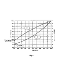
図1は、ファンモータのシャフト出力(1)及びモータ速度の機能としてのファンのフローノイズ(2)を示す。ファンホイールのトルク需要は、2つのモータ速度のパワーを増加させる。結果として、モータのシャフトの出力は、さらに3つのモータ速度のパワーを増加する。これは、例えば、モータの、半分のモータ速度出力は、関係するパワーの12,5%に達するだけである。シャフトの出力は、モータ速度が関係するモータ速度21.5%より小さい場合に、1%を下回る。フローノイズ(2)は、モータ速度が半分になったときに、15−17db(A)に落ちることが経験的にわかっている。 FIG. 1 shows fan motor flow noise (2) as a function of fan motor shaft output (1) and motor speed. Fan wheel torque demand increases the power of the two motor speeds. As a result, the motor shaft output further increases the power of three motor speeds. This is, for example, that a motor's half motor speed output only reaches 12.5% of the power involved. The output of the shaft is less than 1% when the motor speed is less than the related motor speed of 21.5%. It is empirically known that the flow noise (2) falls to 15-17 db (A) when the motor speed is halved.
エネルギ需要に加えて、ノイズはまた、それ故、モータ速度制御ファンモータが使用され、モータ速度のオープンループコントロール及びそれ故エアラインが要求に従って実行された場合に、低下する。ファンのモータ速度は、使用されるモータのタイプの機能としての異なる方法において影響を受ける。直流モータの場合において、モータ速度のオープンループコントロールは、モータ電圧を用いて実行される。コントロールユニットは、クロックド電圧コンバータ(チョッパー)又は制御された整流器を用いてモータ電圧を予め決めることができる。ユニバーサルモータについては、交流電圧の振幅が位相角コントローラを用いて設定され得る。 In addition to energy demand, noise is therefore also reduced when motor speed control fan motors are used and open loop control of motor speed and hence airlines are performed as required. Fan motor speed is affected in different ways as a function of the type of motor used. In the case of a DC motor, open loop control of motor speed is performed using motor voltage. The control unit can predetermine the motor voltage using a clocked voltage converter (chopper) or controlled rectifier. For universal motors, the amplitude of the alternating voltage can be set using a phase angle controller.
ブラシレスモータ(BLDC又はECモータとして参照される電気的に整流されたモータ)の場合において、コントロールユニットは、電気的な整流を行う。コントロールユニットは、付加的に、モータ電圧に影響を与え、結果として、対応する整流電子機器におけるトランジスタのクロッキングを通じてモータ速度に影響を与える。非同期モータの場合には、周波数及びモータ電圧の振幅が周波数コンバータによって予め決められ、又は、コスト効果の良いシステム、特にファンドライブの場合には、モータ電圧のみが、例えば、位相角コントローラ(スリップコントローラとして参照される)を用いて変えられる。 In the case of brushless motors (electrically rectified motors referred to as BLDC or EC motors), the control unit performs electrical rectification. The control unit additionally affects the motor voltage and consequently the motor speed through the clocking of the transistors in the corresponding rectifying electronics. In the case of an asynchronous motor, the frequency and the amplitude of the motor voltage are predetermined by a frequency converter, or in the case of a cost-effective system, in particular a fan drive, only the motor voltage is, for example, a phase angle controller (slip controller). Can be changed using
望まれるモータ速度は、通常、多重のオープンループコントロールを用いて決められる。モータ速度のセットポイント値は、しばしば、アナログ値(例えば0−10V)で送信され、又は、パルス幅が変調された、デジタル値(PWM)で送信される。図2は、ファンアプリケーションの典型である入力特性を示す。この例において、多重化されたコントローラが、停止している(nsetp=0)モータに関して0−10%のコントロール信号(x)を出力しなければならない。この方法の不利な点は、故障の場合、例えば、ラインの損傷、又はコントロールラインにおけるショートの場合において、ファンが停止することである。この場合において、十分な冷却を保証することができず、システムの故障に繋がり得る。結果として、重大な材料の損傷が、製造物の欠陥による多大な損実を引き起こし得る。 The desired motor speed is usually determined using multiple open loop controls. The motor speed setpoint value is often transmitted as an analog value (e.g., 0-10V) or as a digital value (PWM) with a modulated pulse width. FIG. 2 shows the input characteristics typical of fan applications. In this example, the multiplexed controller must output a 0-10% control signal (x) for a motor that is stopped (n setp = 0). The disadvantage of this method is that the fan stops in the event of a failure, for example in the case of a damaged line or a short in the control line. In this case, sufficient cooling cannot be ensured, leading to system failure. As a result, significant material damage can cause significant loss due to product defects.
本発明は、それ故、そのような故障の場合に、モータが所定のモータ速度で作動し続けるような方法で、コントロールユニットの入力特性を構成する目的に基づく。ラインの損傷、又は、コントロールラインのショート、又は、多重化されたコントローラの故障のような故障の場合、コントロール信号xが0%又は100%の値を記録するという可能性が高い。 The invention is therefore based on the object of configuring the input characteristics of the control unit in such a way that in the event of such a failure, the motor continues to operate at a predetermined motor speed. In the case of a fault, such as a damaged line, a shorted control line, or a multiplexed controller fault, the control signal x is likely to record a value of 0% or 100%.
本発明によれば、慣例上の入力特性は、それ故、最初に、約0%又は100%といった特定の範囲における入力値の場合、コントローラが、現在のセットポイント値とは異なる所定のセットポイント値でモータを駆動するという方法で、図2に従って変えられる。 In accordance with the present invention, the customary input characteristic is therefore a predetermined setpoint where the controller initially differs from the current setpoint value for input values in a particular range, such as about 0% or 100%. In the manner of driving the motor by value, it can be changed according to FIG.
ある有利な実施形態において、コントローラは、付加的に、そのような故障の場合に、警告を出力する。この警告は、アナログ又はデジタル電気信号又は、例えばCANバスのような整流バスによって、可視的な又は音響的な信号で出力され得る。 In one advantageous embodiment, the controller additionally outputs a warning in case of such a failure. This warning can be output with a visual or acoustic signal by means of an analog or digital electrical signal or a rectifying bus, for example a CAN bus.
図3は、有利な実施形態におけるコントロールユニットの入力特性を示す。この例において、多重化されたコントローラは、モータを止めるために、0−10%の代わりに、5−10%のコントロール信号(x)を出力しなければならない。アナログコントロール信号(0−10V)の場合において、これは、0.5Vから1Vのコントロール電圧の場合にモータが静止している(nsetp=0)ことを意味する。0.5Vよりも小さなコントロール電圧は、故障(例えば、多重化されたコントローラの故障、ラインの損傷、又はコントロールラインにおけるショート)を示す。
FIG. 3 shows the input characteristics of the control unit in an advantageous embodiment. In this example, the multiplexed controller must output a 5-10% control signal (x) instead of 0-10% to stop the motor. In the case of an analog control signal (0-10V), this means that the motor is stationary (n setp = 0) for control voltages between 0.5V and 1V. A control voltage less than 0.5V indicates a failure (eg, multiplexed controller failure, line damage, or short in control line).
セットポイント値がPWM制御デジタル信号で予め決められているときは、モータは、5から10%PWMのコントロール信号が与えられる静止した状態になる。5%よりも小さなPWMファクターは、故障である。これは、例えば、コントロール信号が連続的に低いレベル(0%PWMに対応する)であった場合である。この場合において、モータ速度の所定のセットポイント値が使用される。図3において、この値は、故障nsetp=100%についてのものである。例えば、ファンを伴うようなアプリケーションについては、それ故、信頼できる操作がセットポイント値の移動における故障の場合でさえも保証される。ファンアプリケーション、パワー及びノイズが、そのような故障が起きたときに低減しないのであるが、十分な冷却が保証される。 When the setpoint value is predetermined by the PWM control digital signal, the motor enters a stationary state where a control signal of 5 to 10% PWM is given. A PWM factor of less than 5% is a failure. This is the case, for example, when the control signal is continuously at a low level (corresponding to 0% PWM). In this case, a predetermined setpoint value of the motor speed is used. In FIG. 3, this value is for the fault n setp = 100%. For example, for an application involving a fan, reliable operation is therefore guaranteed even in the case of a failure in the movement of the setpoint value. Fan application, power and noise are not reduced when such a failure occurs, but sufficient cooling is guaranteed.
モータ速度の最大(100%)のセットポイント値と異なるセットポイント値がまた、故障の場合に使用され得る。ある場合には、低下されたモータ速度は、通常の状況において、冷却するのに十分であり、最大のモータ速度(100%)は、特定の例外的な状況、例えば、並列に駆動するファンの1つの故障についてのみ提供される。図4は、nsetp=75%のセットポイント値が検出された故障に対して使用された場合の、コントロールユニットの発明の入力特性を示す。この値は、それ故、コントロール信号が、0−5%及び95%−100%の範囲内でx値を仮定した場合に使用される。 A setpoint value different from the maximum (100%) setpoint value of the motor speed can also be used in case of a failure. In some cases, the reduced motor speed is sufficient to cool under normal circumstances, and the maximum motor speed (100%) is the maximum in certain exceptional situations, eg, fans that are driven in parallel. Provided for only one failure. FIG. 4 shows the input characteristics of the control unit invention when a setpoint value of n setp = 75% is used for the detected fault. This value is therefore used when the control signal assumes an x value in the range of 0-5% and 95% -100%.
図4にしたがって、入力特性曲線を実行するために、アナログコントロール信号が、最初に、アナログ/デジタルコンバータを使用して、デジタル値に変換され得る。その信号は、その後、さらに、デジタル形式で処理される。本発明における、ある望ましい改良において、これは、マイクロプロセッサ、デジタル信号プロセッサ(DSP)、又はマイクロコントローラによって実行され得る。入力特性曲線を実行するためのプログラムシーケンスが、図5に例示される。 According to FIG. 4, to perform the input characteristic curve, the analog control signal can first be converted to a digital value using an analog / digital converter. The signal is then further processed in digital form. In certain desirable improvements in the present invention, this may be performed by a microprocessor, digital signal processor (DSP), or microcontroller. A program sequence for executing the input characteristic curve is illustrated in FIG.
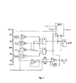
本発明のさらなる改良において、入力特性曲線が、電気アナログ回路を使用して実行される。図6は、これに関する例示的な回路を示す。この回路は、4つのアナログコンパレータ(K1からK4)、2つの演算増幅器、2つのデジタルNANDゲート、及び1つのアナログマルチプレクサ(MUX)から構成される。コンパレータは、図4に従って入力特性における欠陥でコントロール信号xと電圧値、すなわち、0.5V、1V、9V、9.5Vとを比較する。これらの電圧は、直列抵抗を伴う10Vの供給電圧から生成される。コンパレータの出力信号は、さらに、NANDゲートで処理され、以下の表に示されるようにアナログマルチプレクサをコントロールする。

「F」は、ここでは故障に関して予め決められたセットポイント値である。この値は、例えば、図4のように、75%の場合、7.5Vがここに結合されなければならない。 Here, “F” is a set point value determined in advance for the failure. If this value is 75%, for example, as in FIG. 4, 7.5V must be coupled here.
この回路は、図7に例示されるように、警告出力(W)で補足され得る。正常な状況において、この出力は、ロジック「1」を与え、故障の場合には、ロジック「0」を与える。この警告は、コントロール信号xが値を0.5Vよりも小さいか、または9.5Vよりも大きいと仮定した場合の出力である。 This circuit can be supplemented with a warning output (W), as illustrated in FIG. Under normal circumstances, this output provides a logic “1” and in the event of a failure, it provides a logic “0”. This warning is an output when the control signal x is assumed to have a value smaller than 0.5V or larger than 9.5V.
本発明によるコントロールユニットは、別々のユニットを構成でき、又は、モータとコントロールユニットが1つのメカニカルユニットを構成するように、モータハウジング内、又はモータのターミナルボックス内に組み込み可能である。本発明による解決はまた、コントロールユニット及びモータがコンパクトファンの部品に組み込まれ得るコンパクトファン内に有利に用いられる。本発明による解決は、しかしながら、ファン、ブロワ及びポンプ内だけでなく、故障の場合に、モータを停止させるよりも所定のモータ速度で作動させた方がより有益であるような、いかなる装置内にも用いることができる。同様に、本発明は、図示され、記述された例示的な実施形態に限定されず、本発明の範囲内で効果的な全ての実施形態を含むものである。 The control unit according to the invention can be configured as separate units or can be incorporated in the motor housing or in the terminal box of the motor so that the motor and the control unit form one mechanical unit. The solution according to the invention is also advantageously used in a compact fan in which the control unit and the motor can be integrated into the parts of the compact fan. The solution according to the invention, however, is not only in fans, blowers and pumps, but in any device where it is more beneficial to operate at a given motor speed than to stop the motor in case of failure. Can also be used. Similarly, the invention is not limited to the illustrated and described exemplary embodiments, but includes all embodiments that are effective within the scope of the invention.
Claims (15)
コントロール値が、コントロール電圧におけるゼロではない第1の閾値未満の範囲にある場合及び/又は変調におけるゼロではない第1の閾値未満の範囲にある場合に、所定のセットポイント値で前記電気モータを制御し、かつ、
コントロール値が、コントロール電圧における前記第1の閾値と当該第1の閾値よりも高い第2の閾値との間の範囲にある場合及び/又は変調における前記第1の閾値と当該第1の閾値よりも高い第2の閾値との間の範囲にある場合に、前記電気モータを停止させることを特徴とするコントロールユニット。A control unit for at least one electric motor, in the case of a control value in a specific range resulting in a typical failure, the setpoint value is, for example, a predetermined value that is a broken line, a voltage failure or a short circuit Perform an open-loop or closed-loop control of the motor speed of the electric motor to drive the motor with a predetermined setpoint value different from the current control value when in failure ,
When the control value is in a range below a first non-zero threshold in the control voltage and / or in a range below a first non-zero threshold in the modulation, the electric motor is at a predetermined setpoint value. Control and
When the control value is in a range between the first threshold value in the control voltage and the second threshold value higher than the first threshold value and / or from the first threshold value and the first threshold value in the modulation high if the range between the second threshold value, the control unit, characterized in Rukoto stopping the electric motor also.
コントロール値が、コントロール電圧における0.5Vから1Vの間の範囲及び/又は変調における5%から10%の範囲にある場合に、前記電気モータを停止させる請求項1から14のいずれか1項に記載のコントロールユニット。15. The electric motor according to any one of claims 1 to 14, wherein the electric motor is stopped when a control value is in the range between 0.5V and 1V in the control voltage and / or in the range 5% to 10% in the modulation. Control unit as described.
Applications Claiming Priority (3)
| Application Number | Priority Date | Filing Date | Title |
|---|---|---|---|
| DE202006007136U DE202006007136U1 (en) | 2006-05-04 | 2006-05-04 | Control unit for an electric motor, in particular for a fan motor |
| DE202006007136.9 | 2006-05-04 | ||
| PCT/EP2007/054301 WO2007128772A1 (en) | 2006-05-04 | 2007-05-03 | Control unit for an electric motor, in particular for a fan motor |
Publications (3)
| Publication Number | Publication Date |
|---|---|
| JP2009536012A JP2009536012A (en) | 2009-10-01 |
| JP2009536012A5 JP2009536012A5 (en) | 2012-09-20 |
| JP5164974B2 true JP5164974B2 (en) | 2013-03-21 |
Family
ID=36710335
Family Applications (1)
| Application Number | Title | Priority Date | Filing Date |
|---|---|---|---|
| JP2009508349A Expired - Fee Related JP5164974B2 (en) | 2006-05-04 | 2007-05-03 | Control unit for electric motors, especially fan motors |
Country Status (7)
| Country | Link |
|---|---|
| US (2) | US8120298B2 (en) |
| EP (1) | EP2013966B1 (en) |
| JP (1) | JP5164974B2 (en) |
| CN (1) | CN101438489B (en) |
| AT (1) | ATE476783T1 (en) |
| DE (2) | DE202006007136U1 (en) |
| WO (1) | WO2007128772A1 (en) |
Families Citing this family (11)
| Publication number | Priority date | Publication date | Assignee | Title |
|---|---|---|---|---|
| US8264192B2 (en) | 2009-08-10 | 2012-09-11 | Emerson Climate Technologies, Inc. | Controller and method for transitioning between control angles |
| US8508166B2 (en) | 2009-08-10 | 2013-08-13 | Emerson Climate Technologies, Inc. | Power factor correction with variable bus voltage |
| US8698433B2 (en) * | 2009-08-10 | 2014-04-15 | Emerson Climate Technologies, Inc. | Controller and method for minimizing phase advance current |
| US8988025B2 (en) * | 2012-01-20 | 2015-03-24 | GM Global Technology Operations LLC | Systems and methods for controlling a brushless motor |
| US9634593B2 (en) | 2012-04-26 | 2017-04-25 | Emerson Climate Technologies, Inc. | System and method for permanent magnet motor control |
| EP2883302B1 (en) | 2012-08-10 | 2020-09-30 | Emerson Climate Technologies, Inc. | Motor drive control using pulse-width modulation pulse skipping |
| US10056807B2 (en) | 2014-12-23 | 2018-08-21 | Orange Motor Company L.L.C. | Electronically commutated fan motors and systems |
| DE102016001824A1 (en) | 2016-02-17 | 2017-08-17 | András Lelkes | Control method for a cooling system with variable cooling capacity and cooling system |
| DE102016006888A1 (en) * | 2016-06-03 | 2017-12-07 | Liebherr-Hausgeräte Ochsenhausen GmbH | fan |
| DE102021118806B3 (en) | 2021-07-21 | 2022-10-13 | Pierburg Pump Technology Gmbh | Method for controlling an electrically driven fluid pump for a vehicle and an electrically driven fluid pump for a vehicle |
| DE102022110180A1 (en) * | 2022-04-27 | 2023-11-02 | Schaeffler Technologies AG & Co. KG | Method for pump operation, pump control and cooling device |
Family Cites Families (15)
| Publication number | Priority date | Publication date | Assignee | Title |
|---|---|---|---|---|
| US3778696A (en) * | 1972-06-23 | 1973-12-11 | Allen Bradley Co | Feedback fault indicate circuit |
| JPS62236377A (en) * | 1986-04-08 | 1987-10-16 | Toshiba Corp | Wire disconnection detector for speed controller |
| US5023531A (en) | 1988-05-19 | 1991-06-11 | Arx, Inc. | Dual hybrid demand refrigeration control apparatus |
| US5592058A (en) * | 1992-05-27 | 1997-01-07 | General Electric Company | Control system and methods for a multiparameter electronically commutated motor |
| US5744921A (en) * | 1996-05-02 | 1998-04-28 | Siemens Electric Limited | Control circuit for five-phase brushless DC motor |
| US5889469A (en) * | 1997-08-14 | 1999-03-30 | Jmr Electronics, Inc. | Fan pulse alarm using two stage comparator for speed detection |
| JPH11103585A (en) * | 1997-09-29 | 1999-04-13 | Matsushita Refrig Co Ltd | Inverter protector |
| WO2001020762A1 (en) * | 1999-09-15 | 2001-03-22 | Robert Bosch Gmbh | Electronically commutated motor |
| JP2002199789A (en) * | 2000-12-28 | 2002-07-12 | Fuji Electric Co Ltd | Controller for alternating-current motor |
| DE10135286B4 (en) | 2001-07-19 | 2006-04-27 | Siemens Ag | Method and device for bridging short-term power failures in a matrix converter |
| US6791209B2 (en) * | 2002-01-02 | 2004-09-14 | Intel Corporation | Power and control for power supply fans |
| DE10223384A1 (en) * | 2002-05-25 | 2003-12-04 | Conti Temic Microelectronic | Method for operating an electric motor |
| JP2005312149A (en) * | 2004-04-20 | 2005-11-04 | Matsushita Electric Ind Co Ltd | Collision detecting apparatus and method |
| US7548007B2 (en) * | 2004-06-14 | 2009-06-16 | Comair Rotron Inc. | Rotor shaft coupling |
| TWI289382B (en) * | 2005-10-27 | 2007-11-01 | Delta Electronics Inc | Apparatus and method for controlling rotation speed of a fan |
-
2006
- 2006-05-04 DE DE202006007136U patent/DE202006007136U1/en not_active Expired - Lifetime
-
2007
- 2007-05-03 CN CN2007800158403A patent/CN101438489B/en not_active Expired - Fee Related
- 2007-05-03 JP JP2009508349A patent/JP5164974B2/en not_active Expired - Fee Related
- 2007-05-03 US US12/299,426 patent/US8120298B2/en not_active Expired - Fee Related
- 2007-05-03 WO PCT/EP2007/054301 patent/WO2007128772A1/en active Application Filing
- 2007-05-03 EP EP07728754A patent/EP2013966B1/en not_active Not-in-force
- 2007-05-03 DE DE502007004651T patent/DE502007004651D1/en active Active
- 2007-05-03 AT AT07728754T patent/ATE476783T1/en active
-
2012
- 2012-01-31 US US13/363,028 patent/US20130127386A2/en not_active Abandoned
Also Published As
| Publication number | Publication date |
|---|---|
| ATE476783T1 (en) | 2010-08-15 |
| US8120298B2 (en) | 2012-02-21 |
| DE202006007136U1 (en) | 2006-07-06 |
| CN101438489B (en) | 2013-01-16 |
| DE502007004651D1 (en) | 2010-09-16 |
| US20130127386A2 (en) | 2013-05-23 |
| US20090091279A1 (en) | 2009-04-09 |
| EP2013966A1 (en) | 2009-01-14 |
| JP2009536012A (en) | 2009-10-01 |
| EP2013966B1 (en) | 2010-08-04 |
| US20120256576A1 (en) | 2012-10-11 |
| CN101438489A (en) | 2009-05-20 |
| WO2007128772A1 (en) | 2007-11-15 |
Similar Documents
| Publication | Publication Date | Title |
|---|---|---|
| JP5164974B2 (en) | Control unit for electric motors, especially fan motors | |
| JP5454596B2 (en) | Power control device | |
| JP4792849B2 (en) | DC power supply for air conditioner | |
| JP2009536012A5 (en) | ||
| JP2009198139A (en) | Brushless motor driving device for compressor of air conditioner | |
| JP2009124776A (en) | Drive unit of brushless dc motor, and ventilation air blower mounted with it | |
| US11855563B2 (en) | Motor controllers and methods for controlling drive circuit bypass signals | |
| US20100019703A1 (en) | Dual power supply type brushless fan motor speed control device | |
| JP2013102658A (en) | Motor driving device, and electric apparatus using the same | |
| CN108811431A (en) | Heat dissipation system and heat dissipation system stabilizing method | |
| US8138710B2 (en) | Power drive of electric motor | |
| JP4422514B2 (en) | Power converter | |
| US11473584B2 (en) | Method of starting a fan using an open loop starting stage with a decreasing drive signal value | |
| JP6066839B2 (en) | Control device and air conditioner provided with the control device | |
| JP6040066B2 (en) | Fan motor drive control device | |
| JP5838895B2 (en) | Rotational speed detection device and compressor control device | |
| WO2018142738A1 (en) | Air conditioner | |
| US11933309B2 (en) | Method of starting a fan using an open loop starting stage with a decreasing drive signal value | |
| CN220286016U (en) | Fan control circuit, circuit board, fan and electronic equipment | |
| JP6311112B2 (en) | Brushless DC motor | |
| US10797626B2 (en) | Motor drive control device and control method for motor drive control device | |
| JP2012110146A (en) | Converter circuit | |
| EP3057222A1 (en) | Rectifying device and motor driving device | |
| JP2011217504A (en) | Motor drive device | |
| JP2008160916A (en) | Blower driver |
Legal Events
| Date | Code | Title | Description |
|---|---|---|---|
| A621 | Written request for application examination |
Free format text: JAPANESE INTERMEDIATE CODE: A621 Effective date: 20100127 |
|
| A131 | Notification of reasons for refusal |
Free format text: JAPANESE INTERMEDIATE CODE: A131 Effective date: 20120330 |
|
| A601 | Written request for extension of time |
Free format text: JAPANESE INTERMEDIATE CODE: A601 Effective date: 20120626 |
|
| A602 | Written permission of extension of time |
Free format text: JAPANESE INTERMEDIATE CODE: A602 Effective date: 20120703 |
|
| A601 | Written request for extension of time |
Free format text: JAPANESE INTERMEDIATE CODE: A601 Effective date: 20120727 |
|
| A524 | Written submission of copy of amendment under article 19 pct |
Free format text: JAPANESE INTERMEDIATE CODE: A524 Effective date: 20120731 |
|
| A602 | Written permission of extension of time |
Free format text: JAPANESE INTERMEDIATE CODE: A602 Effective date: 20120803 |
|
| TRDD | Decision of grant or rejection written | ||
| A01 | Written decision to grant a patent or to grant a registration (utility model) |
Free format text: JAPANESE INTERMEDIATE CODE: A01 Effective date: 20121130 |
|
| A61 | First payment of annual fees (during grant procedure) |
Free format text: JAPANESE INTERMEDIATE CODE: A61 Effective date: 20121218 |
|
| FPAY | Renewal fee payment (event date is renewal date of database) |
Free format text: PAYMENT UNTIL: 20151228 Year of fee payment: 3 |
|
| R150 | Certificate of patent or registration of utility model |
Free format text: JAPANESE INTERMEDIATE CODE: R150 |
|
| R250 | Receipt of annual fees |
Free format text: JAPANESE INTERMEDIATE CODE: R250 |
|
| R250 | Receipt of annual fees |
Free format text: JAPANESE INTERMEDIATE CODE: R250 |
|
| LAPS | Cancellation because of no payment of annual fees |