JP5164751B2 - Telescopic cover device - Google Patents
Telescopic cover device Download PDFInfo
- Publication number
- JP5164751B2 JP5164751B2 JP2008227509A JP2008227509A JP5164751B2 JP 5164751 B2 JP5164751 B2 JP 5164751B2 JP 2008227509 A JP2008227509 A JP 2008227509A JP 2008227509 A JP2008227509 A JP 2008227509A JP 5164751 B2 JP5164751 B2 JP 5164751B2
- Authority
- JP
- Japan
- Prior art keywords
- cover
- plate
- covering
- moving
- moving body
- Prior art date
- Legal status (The legal status is an assumption and is not a legal conclusion. Google has not performed a legal analysis and makes no representation as to the accuracy of the status listed.)
- Active
Links
Images


Classifications
-
- B—PERFORMING OPERATIONS; TRANSPORTING
- B23—MACHINE TOOLS; METAL-WORKING NOT OTHERWISE PROVIDED FOR
- B23Q—DETAILS, COMPONENTS, OR ACCESSORIES FOR MACHINE TOOLS, e.g. ARRANGEMENTS FOR COPYING OR CONTROLLING; MACHINE TOOLS IN GENERAL CHARACTERISED BY THE CONSTRUCTION OF PARTICULAR DETAILS OR COMPONENTS; COMBINATIONS OR ASSOCIATIONS OF METAL-WORKING MACHINES, NOT DIRECTED TO A PARTICULAR RESULT
- B23Q11/00—Accessories fitted to machine tools for keeping tools or parts of the machine in good working condition or for cooling work; Safety devices specially combined with or arranged in, or specially adapted for use in connection with, machine tools
- B23Q11/08—Protective coverings for parts of machine tools; Splash guards
- B23Q11/0825—Relatively slidable coverings, e.g. telescopic
Description
本発明は、移動体に取り付けられ、移動体の移動方向に伸縮自在であると共に、飛散する飛散物質や光等が移動体等の内部に侵入することを阻止する伸縮カバー装置に関する。 The present invention relates to an expansion / contraction cover device that is attached to a moving body and can be expanded and contracted in the moving direction of the moving body, and prevents scattered substances, light, and the like from entering the inside of the moving body.
従来、昇降自在な工作ユニット(移動体)に用いられ、上下方向に平行に配置された一対のガイドレールと、一対のガイドレールの間に設けられ、工作ユニットの昇降方向に伸縮自在な伸縮カバー機構とを備え、伸縮カバー機構は矩形状の被覆板を有する複数の被覆部材と各被覆部材を連結する伸縮自在なパンタグラフ式リンク機構とで構成される伸縮カバー装置が知られている(例えば、特許文献1参照)。 Conventionally, it is used for a work unit that can be raised and lowered (moving body), and is provided between a pair of guide rails arranged in parallel in the vertical direction, and a telescopic cover that is extendable in the raising and lowering direction of the machine unit. There is known a telescopic cover device comprising a plurality of covering members having a rectangular covering plate and a telescopic pantograph-type link mechanism that connects the respective covering members (for example, Patent Document 1).
特許文献1のものでは、工作ユニットの上方に位置する複数の被覆板を板厚方向に重ね合わせて被覆板相互間で上下方向にスライド自在に構成される上側被覆板群と、工作ユニットの下方に位置する複数の被覆板を板厚方向に重ね合わせて被覆板相互間で上下方向にスライド自在に構成される下側被覆板群との対応する被覆板同士をガイドレールを上下に摺動自在な連結部材で連結され、上下一体の伸縮カバー機構が構成されている。
In the thing of
特許文献1のものは、いわゆる一体型といわれるものであり、上下方向の伸縮性に優れるが、工作ユニット等のメンテナンスを行う際に伸縮カバー装置を取り外す必要があり、メンテナンスし難いという問題がある。
The thing of
ここで、一対のガイドレール間に上下一対の伸縮カバー機構を設け、上側伸縮カバー機構の最も上に位置する被覆部材をガイドレールの上端部に固定し、最も下に位置する被覆部材を工作ユニットの前面カバーの上面に固定すると共に、下側伸縮カバー機構の最も下に位置する被覆部材をガイドレールの下端部に固定し、最も上に位置する被覆部材を工作ユニットの前面カバーの下面に固定し、各伸縮カバー機構の各被覆部材を2つのパンタグラフ式リンク機構により連結されたものも知られている(例えば、特許文献2参照)。 Here, a pair of upper and lower telescopic cover mechanisms are provided between the pair of guide rails, the uppermost covering member of the upper telescopic cover mechanism is fixed to the upper end of the guide rail, and the lowermost covering member is the machine unit. Fixed to the upper surface of the front cover, and the lowermost cover member of the lower telescopic cover mechanism is fixed to the lower end of the guide rail, and the uppermost cover member is fixed to the lower surface of the front cover of the machine unit And what connected each coating | coated member of each expansion-and-contraction cover mechanism with two pantograph type link mechanisms is also known (for example, refer patent document 2).
特許文献2のものは、いわゆる分割型といわれるものであり、例えば、工作ユニットを上方へ移動させて上側伸縮カバー機構を縮めた状態で、下側伸縮カバー機構の最も上に位置する被覆部材を前面カバーから取り外して、下側伸縮カバー機構を下方へ縮めることにより、工作ユニットの下方を開口させることができる。これにより、伸縮カバー装置を取り外すことなく工作ユニット等のメンテナンスを容易に行うことができ、便利である。
従来の分割型の伸縮カバー装置は、伸縮カバー機構が延びるに従って被覆部材の重なり合う面積が小さくなるため被覆部材が傾き易く、伸縮性が悪いという問題がある。特許文献2のものでは、伸縮カバー機構に設けられるパンタグラフ式リンク機構を2つ用いることにより伸縮性の向上を図っているが、それでも一体型と比較すると伸縮性が悪いものであった。
The conventional split type expansion and contraction cover device has a problem that the covering member tends to be inclined and the stretchability is poor because the overlapping area of the covering member becomes smaller as the extension and contraction cover mechanism extends. In
以上の点に鑑み、本発明は、分割型で、伸縮性を向上させた伸縮カバー装置を提供することを目的とする。 In view of the above points, an object of the present invention is to provide a stretchable cover device that is split and has improved stretchability.
上記目的を達成するため、本発明では、移動体の移動方向に平行に配置される一対のガイドレールと、一対のガイドレールの間に設けられ、移動体の移動方向に伸縮自在な伸縮カバー機構とを備え、この伸縮カバー機構は、矩形状の被覆板を有し被覆板の板厚方向に重ね合わされた複数の被覆部材と、各被覆部材を相互間で移動体の移動方向にスライド自在に連結して伸縮自在とするリンク機構とで構成される伸縮カバー装置であって、伸縮カバー機構は、一対のガイドレールの間であって移動体をその移動方向から挟み込むように一対設けられ、各伸縮カバー機構の移動体の移動方向外方に位置する被覆部材は移動体の移動方向への移動が阻止され、各伸縮カバー機構の移動体の移動方向内方に位置する被覆部材は移動体に取り付け自在であり、移動体の移動に伴って一対の伸縮カバー機構が伸縮するものを以下の如く改良している。 In order to achieve the above object, in the present invention, a pair of guide rails arranged in parallel to the moving direction of the moving body, and a telescopic cover mechanism that is provided between the pair of guide rails and is extendable in the moving direction of the moving body. The telescopic cover mechanism includes a plurality of covering members having a rectangular covering plate and stacked in the thickness direction of the covering plate, and each covering member is slidable in the moving direction of the moving body between each other. A telescopic cover device composed of a link mechanism that can be stretched by being connected, and the telescopic cover mechanism is provided between a pair of guide rails so as to sandwich the moving body from its moving direction. The covering member positioned outward in the moving direction of the movable body of the telescopic cover mechanism is prevented from moving in the moving direction of the moving body, and the covering member positioned inward in the moving direction of the movable body of each telescopic cover mechanism is attached to the moving body. Free to install Ri, is improved as follows what pair of elastic cover mechanism with the movement of the moving body is telescopic.
即ち、本発明は、一対の伸縮カバー機構のうちの少なくとも一方の伸縮カバー機構の各被覆部材には、被覆板のガイドレールと対向する両側縁から被覆板の板厚方向一方へ折れ曲がる側板が設けられ、各側板の移動体の移動方向一方側の端縁には、隣接する被覆板の側板の外面に沿って移動体の移動方向一方側に延び、隣接する被覆板の移動体の移動方向へのスライドを案内する案内片が設けられていることを特徴とする。 That is, according to the present invention, each cover member of at least one of the pair of extendable cover mechanisms is provided with a side plate that bends in the thickness direction of the cover plate from both side edges facing the guide rail of the cover plate. The moving body of each side plate extends to one side in the moving direction of the moving body along the outer surface of the side plate of the adjacent covering plate at the edge of one side of the moving body of the adjacent covering plate. A guide piece for guiding the slide is provided.
本発明によれば、被覆部材は移動体の移動方向他方側の隣接する被覆部材の案内片により側板が案内されながら移動体の移動方向にスライドするため、隣接する被覆部材同士の重なり合う部分の移動体の移動方向の両端の距離を従来のものよりも長くすることができ、被覆部材が傾き難い。従って、伸縮カバー機構の伸縮性を向上させることができる。 According to the present invention, the covering member slides in the moving direction of the moving body while the side plate is guided by the guide piece of the adjacent covering member on the other side in the moving direction of the moving body. The distance between both ends in the moving direction of the body can be made longer than the conventional one, and the covering member is difficult to tilt. Therefore, the stretchability of the stretchable cover mechanism can be improved.
又、一対の伸縮カバー機構のうちの一方の伸縮カバー機構の各被覆部材に案内片を設けても一方の伸縮カバー機構の伸縮性が向上するため、伸縮カバー装置全体としても伸縮性が従来のものより向上するが、両方の伸縮カバー機構の各被覆部材に案内片を設ければ、更に伸縮性をを向上させることができる。 In addition, even if a guide piece is provided on each covering member of one of the pair of expansion / contraction cover mechanisms, the expansion / contraction of the one expansion / contraction cover mechanism is improved. Although it improves more than a thing, if a guide piece is provided in each coating | coated member of both expansion-contraction cover mechanisms, a stretching property can be improved further.
又、分割型であるため、例えば、移動体をその移動方向一方に移動させて移動方向一方側の伸縮カバー機構を縮めた状態で、移動方向他方側の伸縮カバー機構の最も内側に位置する被覆部材を移動体から取り外すことにより、移動体の移動方向他方側の伸縮カバー機構も縮めた状態として、移動体の移動方向他方側を開口させることができる。これにより、伸縮カバー装置自体を取り外すことなく移動体や移動体を移動自在に支持する支持機構等のメンテナンスを行うことができ、一体型のものと比較してメンテナンス性が向上される。 In addition, since it is a split type, for example, the cover that is located on the innermost side of the telescopic cover mechanism on the other side in the moving direction in a state where the movable body is moved in one direction of the moving and the telescopic cover mechanism on the other side in the moving direction is contracted. By removing the member from the moving body, it is possible to open the other side in the moving direction of the moving body in a state where the telescopic cover mechanism on the other side in the moving direction of the moving body is also contracted. This makes it possible to perform maintenance on the movable body and the support mechanism that movably supports the movable body without removing the telescopic cover device itself, and the maintainability is improved as compared with the integrated type.
ここで、両伸縮カバー機構の各被覆部材は、案内片により各被覆板が傾くことを抑制させているが、各被覆部材は、隣接するもの同士が被覆部材の板厚方向に重なり合っているだけであり、板厚方向にガタが生じる虞がある。 Here, each covering member of both the stretchable cover mechanisms suppresses the inclination of each covering plate by the guide piece, but each covering member is overlapped only in the plate thickness direction of the covering member. Therefore, there is a risk of looseness in the thickness direction.
この場合、被覆板の板厚方向を前後方向として、一対のガイドレールを、各被覆部材の側板と対向する側壁部と、この側壁部の前端縁から対向するガイドレール側に向って延びる前壁部と、側壁部の後端縁から対向するガイドレール側に向って延びる後壁部と、各側壁部の内面の前後方向の中間部に、移動体の移動方向に延びて突設される突片とで構成し、各被覆部材の案内片の移動体の移動方向一方側の端縁前方部に、外方へ屈曲する屈曲片を設け、側壁部の突片の前面に屈曲片の後端縁を当接させ、各被覆部材の移動体の移動方向他方側の端部に、ガイドレールの後壁部の前面に摺動自在に当接する当接部を設け、各被覆板の案内片の前端縁をガイドレールの前壁部の後面に当接させればよい。 In this case, with the plate thickness direction of the cover plate as the front-rear direction, the pair of guide rails are provided with a side wall portion facing the side plate of each cover member and a front wall extending from the front edge of the side wall portion toward the guide rail side facing the side wall portion. , A rear wall portion extending from the rear edge of the side wall portion toward the opposing guide rail, and a protrusion extending in the moving direction of the moving body at a middle portion of the inner surface of each side wall portion in the front-rear direction. And a bending piece that bends outward is provided at the front end of one edge of the moving body of the guide member of each covering member, and the rear end of the bending piece is provided on the front surface of the protruding piece of the side wall portion. An abutting portion is provided at the other end of the moving direction of the moving body of each covering member so as to slidably abut against the front surface of the rear wall portion of the guide rail. The front end edge may be brought into contact with the rear surface of the front wall portion of the guide rail.
かかる構成によれば、何れの被覆部材においても、案内片の前端縁がガイドレールの前壁部の後面に当接して、各被覆部材はガイドレールに対して前方へのガタツキが抑制される。又、被覆部材の移動体の移動方向一方側の端部に位置する屈曲片の後端縁が側壁部の突片の前面に当接すると共に、被覆部材の移動体の移動方向他方側の端部に位置する当接部がガイドレールの後壁部の前面に当接することにより、各被覆部材はガイドレールに対して後方へのガタツキが抑制される。従って、各被覆部材はガイドレールに対して前後方向へのガタツキが抑制され、伸縮カバー機構の伸縮性をより向上させることができる。 According to such a configuration, in any covering member, the front end edge of the guide piece abuts on the rear surface of the front wall portion of the guide rail, and the backlash of each covering member with respect to the guide rail is suppressed. In addition, the rear end edge of the bent piece located at the end of one side of the moving member of the covering member abuts the front surface of the protruding piece of the side wall, and the end of the other side of the moving member of the covering member in the moving direction When the abutting portion located at the abuts against the front surface of the rear wall portion of the guide rail, the backlash of each covering member with respect to the guide rail is suppressed. Therefore, backlash in the front-rear direction with respect to each guide member is suppressed, and the stretchability of the stretchable cover mechanism can be further improved.
又、各被覆部材の両側板及び両案内片の後端縁に、ガイドレールの側壁部に向って外方へ延びるフランジを設け、このフランジの先端縁をガイドレールの側壁部の内面に当接させれば、各被覆板の傾きをより抑制させることができ、伸縮カバー機構の伸縮性を更に向上させることができる。 In addition, a flange extending outwardly toward the side wall portion of the guide rail is provided on both side plates of each covering member and both guide pieces, and the leading edge of this flange abuts against the inner surface of the side wall portion of the guide rail. By doing so, the inclination of each covering plate can be further suppressed, and the stretchability of the stretchable cover mechanism can be further improved.
本発明の伸縮カバー装置が用いられる移動体としては、例えば、ワークに対して作業する作業部と、この作業部を挿通させて前方に露出させる貫通孔が形成された前面カバーとを備え、前後方向に直交する方向に移動自在な工作ユニットであってもよい。 The movable body in which the expansion / contraction cover device of the present invention is used includes, for example, a working part that works on a workpiece, and a front cover that is formed with a through hole that is inserted through the working part and exposed forward. The machine unit may be movable in a direction orthogonal to the direction.
又、本発明においては、伸縮カバー機構に流体を噴射する流体噴射機構を備えるものであってもよい。これにより、例えば、作業部によりワークを切削加工する際に飛散する切粉や溶接する際に飛散するスパッタ等の飛散物が被覆部材に付着しても、流体噴射機構により噴射される流体で取り除くことができ、飛散物が被覆部材間に挟まること等によって伸縮カバー機構の伸縮が阻害されることを防止できる。又、流体として、潤滑液を用いれば、被覆部材間の摩擦抵抗が減少し、より伸縮性の向上を図ることができる。 In the present invention, a fluid ejecting mechanism that ejects fluid to the extendable cover mechanism may be provided. Thereby, for example, even if the chips scattered when the work is cut by the working unit or the spatter such as spatter scattered when welding is attached to the covering member, it is removed by the fluid ejected by the fluid ejecting mechanism. It is possible to prevent the expansion / contraction of the expansion / contraction cover mechanism from being hindered by, for example, the scattered matter being sandwiched between the covering members. Further, when a lubricating liquid is used as the fluid, the frictional resistance between the covering members is reduced, and the stretchability can be further improved.
図1に示すように、本発明の実施形態の伸縮カバー装置1は、昇降自在な工作ユニット2(移動体)を支持するユニット支持体3の前面に取り付けられるものであり、ワーク(被作業物)に対して作業する際に、工作ユニット2の作業部から飛散するクーラントや、切削加工する際に飛散する切り粉、溶接加工する際に飛散するスパッタ、紫外線等が工作ユニット2やユニット支持体3内に侵入することを阻止するものである。
As shown in FIG. 1, the
ユニット支持体3は、ベース4の上面後方部に配置され、モータ41aで回転されるボールネジ41によりベース4上を前後方向に進退自在となっている。又、ベース4の前方部には、ワーク(被作業物)Wが載置される載置台42が設けられている。ワークWは図示省略したワーク固定機構により載置台42上で固定される。
The
ユニット支持体3内には、図示省略したモータにより回転自在で上下方向に延びるボールネジ31が配置されている。工作ユニット2はボールネジ31の回転により上下方向に昇降自在となっている。工作ユニット2の前方部には図示省略した貫通孔を有する前面カバー21が設けられ、前面カバー21の貫通孔から前方へ突出し載置台42に載置されたワークWに対して切削加工や溶接等の作業を行う作業部22が設けられている。
A
伸縮カバー装置1は、図2に示すように、上下方向に延びる左右一対のガイドレール5,5と、ガイドレール5,5間の上方に配置される上側伸縮カバー機構6と、ガイドレール5,5間の下方に配置される下側伸縮カバー7とで構成される。
As shown in FIG. 2, the
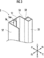
ガイドレール5は、図3に示すように、側壁部51と、側壁部51の前端縁から内方に折れ曲がる前壁部52と、側壁部51の後端縁から内方に折れ曲がる折曲板53と、折曲板53の左右方向内方端縁から後方へ折れ曲がる折曲板54と、折曲板54の左右方向内面に設けられ上下方向に延びる角柱体55と、側壁部51の内面であって前後方向中間部に上下方向に延びて突設された突片56とで構成される。実施形態においては、折曲板53と角柱体55とにより後壁部を構成している。
As shown in FIG. 3, the
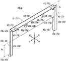
上側伸縮カバー6は、図4に示すように、7つの被覆部材61〜67と、各被覆部材61〜67を連結する2つのパンタグラフ式リンク機構68,68とで構成される。
As shown in FIG. 4, the upper
最も上に位置する被覆部材61は、ガイドレール5,5の上端部に固定されて、工作ユニット2の移動方向である上下方向への移動が阻止されるものであり、図5に示すように、長方形状の被覆板61aと、被覆板61aの左右両端縁から後方へ折れ曲がる側板61b,61bとを備える。側板61bの下端縁には、下方へ延びる案内片61cが設けられている。案内片61cの前端縁と、被覆板61aの前面左右両端部とは、ガイドレール5,5の前壁部52の後面に当接する。
The
各側板61b及び各案内片61cの後端縁には、左右方向外方へ折れ曲がるフランジ61dが設けられている。各フランジ61dの左右方向外方端縁はガイドレール5,5の側壁部51の内面に当接する。各案内片61cの下端縁前方部には、左右方向外側に向って傾斜して延びる屈曲片61eが設けられており、屈曲片61eの後端縁は、ガイドレール5の側壁部51の内面に設けられた突片56の前面56aに当接する。屈曲片61eを傾斜させることにより、屈曲片61eを左右方向外方に向って直角に屈曲させた場合と比較して、屈曲片61eを長くすることができ、これにより、突片56の前面56aと当接する面積を大きくとることができる。
A
被覆部材61は、被覆板61aの上端縁及び側板61b,61bの上端縁に溶接された上板61fを備える。上板61fの後端縁中間部には、左右方向に間隔を存して下方へ折り曲がる一対のピン固定片61gが設けられている。ピン固定片61g,61gには後方へ延びる連結ピンを突設自在な孔部61hが設けられている。上板61fの後端縁左右両端部には、後方へ突出する当接部61iが設けられている。当接部61iの後端縁の左右方向内方部には更に後方に突出しており、これにより当接部61iはL字状となっている。この当接部61iは、後壁部を構成する角柱体55の前面及び左右方向内面に当接する。
The covering
被覆部材61の下方に隣接する被覆部材62は、図6に示すように、被覆部材61と略同一の構成を備える。異なる点としては、被覆板62aが被覆部材61の被覆板61aの後面に重ね合わされた状態で側板61bの間を上下方向に摺動できるように、側板61bの板厚をtとして、被覆板62aの左右方向の長さが被覆板61aよりt×2+Δt(Δtは、例えば、0.3〜0.6mm)だけ短く形成されている。
The covering
又、被覆板62aは、その前面上端部が被覆板61aの後面に摺動自在に当接するように配置されることにより、被覆板61aの板厚をtとして、案内片62cがt+Δtだけ後方へずれる。このため、案内片62cの前端縁がガイドレール5,5の前壁部52の後面に当接するように、案内片62cは案内片61cよりt+Δtだけ前方へ延長されている。
Further, the covering plate 62a is disposed so that the upper end of the front surface thereof is slidably in contact with the rear surface of the covering plate 61a, so that the thickness of the covering plate 61a is t, and the
同様に、フランジ62dもt+Δtだけ左右方向外方に延長されている。又、屈曲片62eもその後端縁がガイドレール5の突片56の前面56aに当接できるように、左右方向と傾斜板62eの傾斜方向とが成す角をθとして、(t+Δt)/cosθだけ斜め下方に延長されている。又、上板62fは、前後方向の長さがt+Δtだけ短く形成されている。
Similarly, the
上板62fの後端縁中間部から下方へ折り曲げられた2つのピン固定片62gは、その上縁から下方に向って大きく切り欠かれてU字状に形成され、切り欠かれた部分で隣接する上方のピン固定片61gを受け入れ自在としている。又、U字状のピン固定片62gは、その下端隅部を弧状に湾曲させた形状とすることにより、隅部を90度に屈曲させたものと比較して隅部の応力集中を比較的緩和させることができる。
The two
又、当接部62iの上面には、上板62fが上板61fに直接接触することを防止する緩衝部材62jが設けられている。他の点は、被覆部材61と同一である。
Further, a
ここで、被覆部材61の案内片61cの上下方向の長さh2は、被覆部材62の被覆板62aの上下方向の長さh1以上に設定されている。これにより、隣接する被覆部材61と被覆部材62とが重なり合う工作ユニット2の移動方向の両端の距離を、従来のものよりも長くすることができ、被覆部材62が被覆部材61に対して傾き難くなって安定して上下方向にスライドすることができる。
Here, the length h 2 in the vertical direction of the guide piece 61 c of the covering
被覆部材63〜67についても、隣接する上方の被覆部材と同様の関係となるように形成される。但し、最も下に位置する被覆部材67には、図7に示すように、ピン固定片に代えて、被覆板67aの後面下方部に孔部67hを有する2つのピン固定用突部67k,67kが突設されている。ピン固定片61g〜66g及びピン固定用突部67kの孔部61h〜67hには、後方に延びる連結ピン61m〜67mが設けられている。
The covering
連結ピン61m、67mには、一対の端部リンクバー68a,68aがその端部で揺動自在に軸支されている。連結ピン62k〜66kには、一対の中間部リンクバー68b,68bがその中央部で揺動自在に軸支されている。端部リンクバー68a及び中間部リンクバー68bの対応する端部同士は連結ピン68cで揺動自在に連結され、これにより各被覆部材61〜67を相互に上下方向にスライド自在に連結するパンタグラフ式リンク機構68が構成される。
A pair of end link bars 68a and 68a are pivotally supported at the ends of the connecting
又、被覆板67aの下端縁及び側板67bには、下板67nが溶接されている。下板67nの上面には上方に突出するストッパー部67pが4つ設けられている。このストッパー部67pは、パンタグラフ式リンク機構68の最も下に位置する端部リンクバー68aと当接することにより、一対の端部リンクバー68aの成す角が180度以上となることを阻止している。
A
これにより、実施形態の伸縮カバー装置1は、一対の端部リンクバー68a,68aの成す角が180度以上となることによって伸縮ストロークが初期状態よりも短くなることがなく、工作ユニット2の昇降動作によって、リンクバー68a,68b等に過度の負荷が加わることによる破損を防止し、耐久性を向上させることができる。
As a result, the
下側伸縮カバー7は、上側伸縮カバー6と同一の構成であり、最も下に位置する被覆部材77がガイドレール5の下端に固定されて、工作ユニット2の移動方向である上下方向への移動が阻止されている。又、最も上に位置する被覆部材71の上板71fの上面には、工作ユニット2の前面カバー21の下面に固定自在な固定板79が設けられている。又、上側伸縮カバー6の最も下に位置する被覆部材67の下板67nの下面には、工作ユニット2の前面カバー21の上面に固定自在な固定板69が設けられている。
The lower
又、ベース4の上面には、ボールネジ41の前方部を覆う前後方向に伸縮自在な前後伸縮カバー装置43が設けられている。前後伸縮カバー装置43は、伸縮カバー機構6,7と同様の構成であり、上側伸縮カバー機構6の被覆部材61〜67に対応する被覆部材431〜437と図示省略したパンタグラフ式リンク機構及び一対のガイドレールとを備える。最も後方に位置する被覆部材431がユニット支持体3の前面下端部に取り付けられ、最も前方に位置する被覆部材437がベース4に固定されている。前後伸縮カバー装置43は、モータ41aによるボールネジ41の回転により前後方向に移動するユニット支持体3と共に前後方向に伸縮する。
Further, a front / rear extending /
次に、伸縮カバー装置1の作動について説明する。伸縮カバー装置1は、ユニット支持体3の前面に取り付けられ、ボールネジ41の回転によりユニット支持体3と共に前後に移動する。工作ユニット2がボールネジ31の回転により上昇すると、前面カバー21の上面に固定された固定板69を介して上側伸縮カバー機構6が上方に押し上げられて縮むと共に、前面カバー21の下面に固定された固定板79を介して下側伸縮カバー機構7が上方に引張されて延びる。逆に、工作ユニット2がボールネジ31の回転により下降すると、前面カバー21の上面に固定された固定板69を介して上側伸縮カバー機構6が下方に引張されて延びると共に、前面カバー21の下面に固定された固定板79を介して下側伸縮カバー機構7が下方に押し下げられて縮む。
Next, the operation of the
実施形態の伸縮カバー装置1によれば、例えば、工作ユニット2を上昇させた状態で前面カバー21の下面から下側伸縮カバー機構7の固定板79を取り外せば、下側伸縮カバー機構7を下方へ縮めることができる。これにより、伸縮カバー装置1をユニット支持体3から取り外すことなく前面カバー21の下方を開口させることができ、工作ユニット2のメンテナンスが行い易くなる。
According to the
又、伸縮カバー機構6,7は、側板61b〜67b,71b〜77bの下端縁から下方に延びる案内片61c〜67c,71c〜77cにより上下方向のスライドが案内されるため、被覆板62a〜67a,72a〜76aが傾き難く、伸縮性を向上させることができる。
Further, since the
又、案内片61c〜67c,71c〜77cの前端縁がガイドレール5の前壁部52の後面に当接するため、各被覆部材61〜67,71〜77はガイドレール5,5に対して前方へのガタツキが抑制される。又、被覆部材61〜67,71〜77の屈曲片61e〜67e,71e〜77eの後端縁が側壁部51の突片56の前面56aに当接すると共に(図9参照)、被覆部材61〜67,71〜77の当接部61i〜67i,71i〜77iがガイドレール5の角柱体55の前面に当接することにより、各被覆部材61〜67,71〜77はガイドレール5,5に対して後方へのガタツキが抑制される。従って、各被覆部材61〜67,71〜77はガイドレール5,5に対して前後方向へのガタツキが抑制され、伸縮カバー機構の伸縮性をより向上させることができる。
Further, since the front end edges of the guide pieces 61c to 67c and 71c to 77c are in contact with the rear surface of the
又、図9に示すように、各被覆部材61〜67,71〜77のフランジ61d〜67d,71d〜77dの先端縁がガイドレール5,5の側壁部51の内面に当接しているため、各被覆部材61〜67,71〜77の傾きをより抑制させることができ、伸縮カバー機構1の伸縮性が更に向上される。
Further, as shown in FIG. 9, the leading edges of the
尚、実施形態の伸縮カバー装置1に、各被覆部材61〜67,71〜77の前面に向けて流体(冷却液、冷却ガス、窒素ガス、不活性ガス等)を噴射する流体噴射機構を設けてもよい。これにより、作業部22で、ワークWを切削加工する際に飛散する切粉や、溶接する際に飛散するスパッタ等の飛散物が被覆部材に付着しても、流体噴射機構により噴射される流体で各被服部材61〜67,71〜77から取り除くことができ、飛散物が被覆部材61〜67,71〜77間に挟まること等によって伸縮カバー機構6,7の伸縮が阻害されることを防止できる。又、流体として、潤滑液を用いれば、被覆部材61〜67,71〜77間の摩擦抵抗が減少し、より伸縮性の向上を図ることができる。
In addition, the expansion /
又、実施形態の伸縮カバー装置1では、案内片61c〜67c,71c〜77cの上下方向の長さh2を、隣接する被覆部材の被覆板の上下方向の長さh1以上としているが、これに限られず、伸縮性が著しく損われなければ、案内片61c〜67c,71c〜77cの上下方向の長さh2を、隣接する被覆部材の被覆板の上下方向の長さh1よりも短くしてもよい。例えば、伸縮カバー機構6,7が最大限に延びたときに、側板61b〜67b,71b〜77b及び案内片61c〜67c,71c〜77cにより隣接する被覆部材の側板の外面を覆うように、案内片61c〜67c,71c〜77cの長さh2を設定してもよい。
Further, the
又、実施形態の伸縮カバー装置1では、伸縮カバー機構として、上下方向に伸縮するものを説明したが、これに限られず、例えば、左右方向に伸縮するものでも同様に本発明を適用することができる。
Moreover, in the expansion /
又、実施形態の伸縮カバー装置1では、被覆部材67,77にストッパー部67p,77pを設けたものを説明したが、被覆部材61,71にもストッパー部を設けてもよい。
Further, in the
又、実施形態の伸縮カバー装置1では、工作ユニット2の移動方向外方に位置する被覆部材61,77をガイドレール5,5に固定することにより、工作ユニット2の移動方向への移動を阻止したものを説明したが、これに限られず、例えば、ガイドレール5,5を支持する部材に固定して工作ユニット2の移動方向への移動を阻止してもよい。
Further, in the
又、実施形態の伸縮カバー装置1では、作業部22を備える工作ユニット2に用いられるものを説明したが、伸縮カバー装置1が用いられる移動体としては、これに限られない。例えば、移動体は、前面に窓部(レンズ)を備え昇降自在なカメラであってもよい。この場合、例えば、窓部の上端縁に、上側伸縮カバー機構6の最も下に位置する被覆部材67を固定板69を介して取付け、窓部の下端縁に、下側伸縮カバー機構の最も上に位置する被覆部材71を固定板79を介して取り付ければよい。これによれば、カメラの内部等に埃等が侵入することを防止することができると共に、カメラのメンテナンスを伸縮カバー装置1を取り外すことなく容易に行うことができる。
Moreover, in the expansion /
1…伸縮カバー装置、 2…工作ユニット、 21…前面カバー、 22…作業部、 5…ガイドレール、 51…側壁部、 52…前壁部、 53…折曲板(後壁部)、 55…角柱体(後壁部)、 56…突片、 6…上側伸縮カバー機構、 61〜67…被覆部材、 61a〜67a…被覆板、 61b〜67b…側板、 61c〜67c…案内片、 61d〜67d…フランジ、 61e〜67e…屈曲片、 61i〜67i…当接部、 68…パンタグラフ式リンク機構、 7…下側伸縮カバー機構、 71〜77…被覆部材、 71a〜77a…被覆板、 71b〜77b…側板、 71c〜77c…案内片、 71d〜77d…フランジ、 71e〜77e…屈曲片、 71i〜77i…当接部、 78…パンタグラフ式リンク機構、 W…ワーク(被作業物)。
DESCRIPTION OF
Claims (4)
一対のガイドレールの間に設けられ、移動体の移動方向に伸縮自在な伸縮カバー機構とを備え、
この伸縮カバー機構は、矩形状の被覆板を有し被覆板の板厚方向に重ね合わされた複数の被覆部材と、各被覆部材を相互間で移動体の移動方向にスライド自在に連結して伸縮自在とするリンク機構とで構成される伸縮カバー装置であって、
伸縮カバー機構は、一対のガイドレールの間であって移動体をその移動方向から挟み込むように一対設けられ、
各伸縮カバー機構の移動体の移動方向外方に位置する被覆部材は移動体の移動方向への移動が阻止され、各伸縮カバー機構の移動体の移動方向内方に位置する被覆部材は移動体に取り付け自在であり、移動体の移動に伴って一対の伸縮カバー機構が伸縮するものにおいて、
一対の伸縮カバー機構のうちの少なくとも一方の伸縮カバー機構の各被覆部材には、被覆板のガイドレールと対向する両側縁から被覆板の板厚方向一方へ折れ曲がる側板が設けられ、
各側板の移動体の移動方向一方側の端縁には、隣接する被覆板の側板の外面に沿って移動体の移動方向一方側に延び、隣接する被覆板の移動体の移動方向へのスライドを案内する案内片が設けられ、
一対のガイドレールは、
各被覆部材の側板と対向する側壁部と、
この側壁部の前端縁から対向するガイドレールに向って延びる前壁部と、
側壁部の後端縁から対向するガイドレール側に向って延びる後壁部と、
各側壁部の内面の前後方向の中間部に、移動体の移動方向に延びて突設される突片とを備え、
各被覆部材の案内片の移動体の移動方向一方側の端縁前方部には、外方へ屈曲する屈曲片が設けられ、側壁部の突片の前面に屈曲片の後端縁が当接し、
各被覆部材の移動体の移動方向他方側の端部には、ガイドレールの後壁部の前面に当接する当接部が設けられ、
各被覆板の案内片の前端縁がガイドレールの前壁部の後面に当接することを特徴とする伸縮カバー装置。 A pair of guide rails arranged parallel to the moving direction of the moving body;
Provided with a telescopic cover mechanism that is provided between a pair of guide rails and is telescopic in the moving direction of the moving body,
This telescopic cover mechanism has a rectangular covering plate and a plurality of covering members stacked in the thickness direction of the covering plate, and each covering member is slidably connected to each other in the moving direction of the movable body to expand and contract. A telescopic cover device configured with a link mechanism that can be freely configured,
A pair of extendable cover mechanisms are provided between the pair of guide rails so as to sandwich the moving body from its moving direction,
The covering member positioned outward in the moving direction of the movable body of each telescopic cover mechanism is prevented from moving in the moving direction of the moving body, and the covering member positioned inward of the moving body of each movable cover mechanism is the moving body. In which the pair of elastic cover mechanisms expands and contracts as the moving body moves,
Each cover member of at least one of the pair of stretch cover mechanisms is provided with a side plate that bends in the thickness direction of the cover plate from both side edges facing the guide rail of the cover plate,
A moving body of each side plate extends to one side in the moving direction of the moving body along the outer surface of the side plate of the adjacent covering plate, and slides in the moving direction of the moving body of the adjacent covering plate on the edge of the side plate of the adjacent covering plate. guide piece for guiding is provided, et al. it is the,
A pair of guide rails
A side wall facing the side plate of each covering member;
A front wall extending from the front edge of the side wall toward the opposing guide rail;
A rear wall portion extending from the rear edge of the side wall portion toward the opposing guide rail,
Provided at the middle part of the inner surface of each side wall part in the front-rear direction, and a projecting piece that projects in the moving direction of the moving body,
A bending piece that bends outward is provided at the front part of the edge on one side in the moving direction of the moving body of the guide member of each covering member, and the rear end edge of the bending piece abuts on the front surface of the protruding piece of the side wall part. ,
An abutting portion that abuts on the front surface of the rear wall portion of the guide rail is provided at the other end of the moving direction of each moving member of the covering member.
A telescopic cover device, wherein the front edge of the guide piece of each covering plate abuts against the rear surface of the front wall portion of the guide rail .
各被覆板の両側板及び両案内片の後端縁に、ガイドレールの側壁部に向って外方へ延びるフランジが設けられ、このフランジの先端縁がガイドレールの側壁部の内面に当接することを特徴とする伸縮カバー装置。 A flange that extends outward toward the side wall portion of the guide rail is provided at the rear end edge of both side plates and both guide pieces of each covering plate, and the leading edge of this flange abuts against the inner surface of the side wall portion of the guide rail. A telescopic cover device characterized by.
移動体は、ワークに対して作業する作業部と、この作業部を挿通させて前方に露出させる貫通孔が形成された前面カバーとを備え、前後方向に直交する方向に移動自在な工作ユニットであることを特徴とする伸縮カバー装置。 The movable body is a work unit that includes a working unit that works on a workpiece and a front cover that is formed with a through-hole that is inserted through the working unit and exposed forward, and is movable in a direction perpendicular to the front-rear direction. A telescopic cover device characterized by being.
伸縮カバー機構に流体を噴射する流体噴射機構を備えることを特徴とする伸縮カバー装置。 A telescopic cover device comprising a fluid ejecting mechanism for ejecting fluid to the telescopic cover mechanism.
Priority Applications (1)
| Application Number | Priority Date | Filing Date | Title |
|---|---|---|---|
| JP2008227509A JP5164751B2 (en) | 2008-09-04 | 2008-09-04 | Telescopic cover device |
Applications Claiming Priority (1)
| Application Number | Priority Date | Filing Date | Title |
|---|---|---|---|
| JP2008227509A JP5164751B2 (en) | 2008-09-04 | 2008-09-04 | Telescopic cover device |
Publications (2)
| Publication Number | Publication Date |
|---|---|
| JP2010058233A JP2010058233A (en) | 2010-03-18 |
| JP5164751B2 true JP5164751B2 (en) | 2013-03-21 |
Family
ID=42185623
Family Applications (1)
| Application Number | Title | Priority Date | Filing Date |
|---|---|---|---|
| JP2008227509A Active JP5164751B2 (en) | 2008-09-04 | 2008-09-04 | Telescopic cover device |
Country Status (1)
| Country | Link |
|---|---|
| JP (1) | JP5164751B2 (en) |
Families Citing this family (2)
| Publication number | Priority date | Publication date | Assignee | Title |
|---|---|---|---|---|
| JP5725618B2 (en) * | 2011-12-21 | 2015-05-27 | 株式会社ナベル | Extension protection device and installation structure of the extension protection device |
| JP6457209B2 (en) * | 2014-07-08 | 2019-01-23 | ファナック株式会社 | Machine tool with protective cover |
Family Cites Families (5)
| Publication number | Priority date | Publication date | Assignee | Title |
|---|---|---|---|---|
| JPS62168240U (en) * | 1986-04-15 | 1987-10-26 | ||
| JPH0613812Y2 (en) * | 1988-10-19 | 1994-04-13 | 榎本工業株式会社 | Machine tool sliding surface protection device |
| JP3741801B2 (en) * | 1996-11-11 | 2006-02-01 | 榎本ビーエー株式会社 | Telesco cover |
| JP3326115B2 (en) * | 1998-07-24 | 2002-09-17 | 榎本工業株式会社 | Y-axis slide cover for machine tools |
| JP2006142435A (en) * | 2004-11-19 | 2006-06-08 | Nippei Toyama Corp | Sealing device |
-
2008
- 2008-09-04 JP JP2008227509A patent/JP5164751B2/en active Active
Also Published As
| Publication number | Publication date |
|---|---|
| JP2010058233A (en) | 2010-03-18 |
Similar Documents
| Publication | Publication Date | Title |
|---|---|---|
| US10244868B2 (en) | Slide rail assembly | |
| JP6715797B2 (en) | Slide rail assembly | |
| US5169223A (en) | Telescopic cover apparatus | |
| JP6228248B2 (en) | Slide rail assembly and its rail kit | |
| JP4650308B2 (en) | Keyboard lid opening / closing mechanism | |
| US10827836B2 (en) | Slide rail assembly | |
| JP5164751B2 (en) | Telescopic cover device | |
| JP6751451B2 (en) | Slide rail assembly | |
| JP6757361B2 (en) | Slide rail assembly and its drive mechanism | |
| TWI620535B (en) | Slide rail assembly | |
| US20170188705A1 (en) | Slide rail assembly | |
| US7412759B1 (en) | Telescopic safety shield for machine tool | |
| JP6994078B2 (en) | Slide rail assembly | |
| TW202116224A (en) | Slide rail assembly | |
| JP6581170B2 (en) | Machine Tools | |
| TW201639497A (en) | Slide rail assembly | |
| US20080080941A1 (en) | Machine tool having a work space | |
| US10660436B2 (en) | Slide rail assembly | |
| JP2020102532A (en) | Multistep hand and transfer robot including the same | |
| JP4467476B2 (en) | Floor joint device | |
| JP2008037513A (en) | Vertical frame centering tool for elevator | |
| JP5164752B2 (en) | Telescopic cover device | |
| JP4844132B2 (en) | Apron equipment for elevator | |
| US11067290B2 (en) | Cabinet and slide rail kit thereof | |
| US11266239B1 (en) | Slide rail assembly |
Legal Events
| Date | Code | Title | Description |
|---|---|---|---|
| A621 | Written request for application examination |
Free format text: JAPANESE INTERMEDIATE CODE: A621 Effective date: 20101126 |
|
| A977 | Report on retrieval |
Free format text: JAPANESE INTERMEDIATE CODE: A971007 Effective date: 20120725 |
|
| A131 | Notification of reasons for refusal |
Free format text: JAPANESE INTERMEDIATE CODE: A131 Effective date: 20120731 |
|
| A521 | Written amendment |
Free format text: JAPANESE INTERMEDIATE CODE: A523 Effective date: 20120921 |
|
| TRDD | Decision of grant or rejection written | ||
| A01 | Written decision to grant a patent or to grant a registration (utility model) |
Free format text: JAPANESE INTERMEDIATE CODE: A01 Effective date: 20121127 |
|
| A61 | First payment of annual fees (during grant procedure) |
Free format text: JAPANESE INTERMEDIATE CODE: A61 Effective date: 20121218 |
|
| FPAY | Renewal fee payment (event date is renewal date of database) |
Free format text: PAYMENT UNTIL: 20151228 Year of fee payment: 3 |
|
| R150 | Certificate of patent or registration of utility model |
Ref document number: 5164751 Country of ref document: JP Free format text: JAPANESE INTERMEDIATE CODE: R150 Free format text: JAPANESE INTERMEDIATE CODE: R150 |
|
| R250 | Receipt of annual fees |
Free format text: JAPANESE INTERMEDIATE CODE: R250 |