JP5164397B2 - Vibration actuator and optical apparatus including the vibration actuator - Google Patents
Vibration actuator and optical apparatus including the vibration actuator Download PDFInfo
- Publication number
- JP5164397B2 JP5164397B2 JP2007058493A JP2007058493A JP5164397B2 JP 5164397 B2 JP5164397 B2 JP 5164397B2 JP 2007058493 A JP2007058493 A JP 2007058493A JP 2007058493 A JP2007058493 A JP 2007058493A JP 5164397 B2 JP5164397 B2 JP 5164397B2
- Authority
- JP
- Japan
- Prior art keywords
- vibration
- vibrator
- reference position
- standing wave
- vibration actuator
- Prior art date
- Legal status (The legal status is an assumption and is not a legal conclusion. Google has not performed a legal analysis and makes no representation as to the accuracy of the status listed.)
- Expired - Fee Related
Links
Images


Landscapes
- General Electrical Machinery Utilizing Piezoelectricity, Electrostriction Or Magnetostriction (AREA)
- Lens Barrels (AREA)
- Apparatuses For Generation Of Mechanical Vibrations (AREA)
Description
本発明は、異物除去機能を有する光学機器に関するものである。 The present invention relates to an optical apparatus having a foreign matter removing function.
弾性体や高摩擦材に圧電素子を圧着し、複数の交流電圧を印加することにより楕円運動を励起することで、推進駆動力を得る振動アクチュエータが知られている。 There is known a vibration actuator that obtains a propulsion driving force by exciting a elliptical motion by pressing a piezoelectric element on an elastic body or a high friction material and applying a plurality of alternating voltages.
この振動アクチュエータでは振動子と固定子の接触面に、塵埃やアクチュエータ自体の磨耗粉が付着すると、耐久性の低下や異音の発生等の問題が生ずる。この問題を解決する方法として、特許文献1では振動アクチュエータの超音波振動により振動子に楕円運動を生じさせ、この楕円運動によって運動部材を相対運動させることによる塵埃除去手段を有し、摺動動作等により異物の除去を行っている。また特許文献2では、塵埃除去部材を多孔質物質により形成し、摺動動作により異物の除去を行っている。
In this vibration actuator, if dust or abrasion powder of the actuator itself adheres to the contact surface between the vibrator and the stator, problems such as deterioration in durability and generation of abnormal noise occur. As a method for solving this problem, in
上述したように、従来では振動アクチュエータ自体に付着した異物除去は摺動動作により行っている。しかし、この摺動動作による異物除去は、ブラシやフェルト、多孔質部材等から成る除去部材が必要であるため、コストアップとなったり、振動アクチュエータが通常の動作を開始するまでに時間がかかるという問題がある。また、異物除去を実行するタイミングについての明確な提案はない。 As described above, conventionally, the foreign matter attached to the vibration actuator itself is removed by a sliding operation. However, the removal of foreign matters by this sliding operation requires a removal member made of a brush, felt, porous member, etc., which increases costs and takes time for the vibration actuator to start normal operation. There's a problem. In addition, there is no clear proposal for the timing of executing foreign matter removal.
本発明の目的は、上述の問題点を解消し、振動により異物を確実に除去することが可能な光学機器を提供することにある。 An object of the present invention is to provide an optical apparatus that can eliminate the above-mentioned problems and can reliably remove foreign matters by vibration.
上記目的を達成するための本発明に係る光学機器の技術的特徴は、振動を発生する振動子及び該振動子に接触する固定子を有し、かつ前記振動子に周期電圧を印加することによりレンズ群を光軸方向に移動させる振動アクチュエータと、前記レンズ群の基準位置を検出する基準位置検出センサとを備える光学機器において、前記基準位置検出センサによる前記レンズ群の基準位置の検出動作前に、前記振動子に定在波の周期電圧を断続的に印加する異物除去振動動作を行うことにある。 In order to achieve the above object, the technical feature of the optical apparatus according to the present invention includes a vibrator that generates vibration and a stator that contacts the vibrator, and a periodic voltage is applied to the vibrator. a vibration actuator for moving the lens unit in the optical axis direction, the optical component must a reference position sensor for detecting a reference position of the lens group, the detection operation prior to the reference position of the lens group by the reference position detecting sensor in is to conduct the different removal oscillating motion intermittently applying a periodic voltage of the standing wave in the vibrator.
本発明に係る光学機器によれば、通常動作前に短時間で異物除去動作を完了することができると共に、低コストで耐久性の向上及び静音化を実現することが可能となる。 According to the optical apparatus of the present invention, the foreign matter removing operation can be completed in a short time before the normal operation, and the durability can be improved and the noise can be reduced at a low cost.
また、異物を吸着する吸着手段を設けることで、異物が再度付着することを防止できる。 Further, by providing an adsorption means for adsorbing foreign matter, it is possible to prevent the foreign matter from adhering again.
更に、周期電圧の印加を断続的に行うことで、振動子の駆動周波数に依存することなく、異物除去に適した振動を振動子及び固定子により励振することができる。 Furthermore, by applying the periodic voltage intermittently, vibration suitable for removing foreign substances can be excited by the vibrator and the stator without depending on the driving frequency of the vibrator.
本発明を図示の実施例に基づいて詳細に説明する。 The present invention will be described in detail based on the embodiments shown in the drawings.
図1は実施例1の直動型の振動アクチュエータを用いた光学機器の断面図である。
固定鏡筒1内にレンズホルダ2が設けられ、このレンズホルダ2にフォーカスレンズ或いは変倍レンズ等のレンズ群3が保持されている。また、レンズホルダ2はスリーブ4を介して保持バー5に取り付けられ、レンズホルダ2、レンズ群3は光軸方向への直進駆動を可能とされている。
FIG. 1 is a cross-sectional view of an optical apparatus using the direct acting vibration actuator of the first embodiment.
A
レンズホルダ2には圧電素子を用いた振動子6が固定され、振動子6は固定鏡筒1に固定された固定子であるスライダ7と接触している。また固定鏡筒1内には、レンズ群3の基準位置を検出する基準位置検出センサ8が設けられ、更にレンズ群3の位置は位置検出センサ9により検出されるようになっている。
A
スライダ7は高摩擦係数と摩擦耐久性を兼ね備えた材料で形成され、振動子6と加圧状態で接触しており、振動子6とスライダ7により振動アクチュエータ10が構成されている。
The
一般的な振動アクチュエータ10では、振動子6を形成する圧電素子に複数回の周期電圧を断続的に印加することで、曲げモード+曲げモード或いは曲げモード+伸縮モードなどの駆動モードを励起する。この駆動モードにより、振動子6を楕円運動させることで、スライダ7に対して相対的な駆動力を得ている。
In a
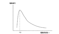
図2は振動子6に印加する周期電圧の駆動周波数fと駆動速度との関係を示している。振動子6に印加する周期電圧を1つだけとすることで、曲げモードや伸縮モード等の単一モードで励振することが可能である。また、複数の周期電圧信号同士の位相を0°或いは180°ずらすことで、推力を得ることなく、振動アクチュエータ10は静止した状態で振動子6を励振することが可能である。この場合の駆動信号は定在波であり、本実施例ではこの定在波を用いて振動子6やスライダ7に付着した異物を振るい落す。更に、この振動はレンズ群3にも伝達されるため、レンズ群3に付着した異物の除去も可能である。
FIG. 2 shows the relationship between the driving frequency f of the periodic voltage applied to the
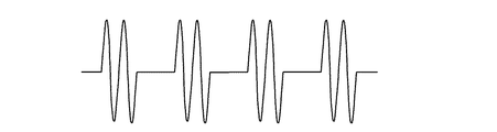
しかし、定在波による振動が最も効率的に得ることが可能な共振周波数f0は数10kHz以上であり、スライダ7やレンズ群3の共振周波数とは異なる場合がある。そのため、図3に示すように数10kHzの定在波の周期電圧を断続的に加えることで、駆動周波数よりも低い周波数の振動を擬似的に発生させることが可能である。このような異物除去振動周波数はスライダ7やレンズ群3の共振周波数、或いは付着している異物の大きさを加味して設定することが望ましい。
However, the resonance frequency f0 at which vibration due to the standing wave can be obtained most efficiently is several tens of kHz or more, and may differ from the resonance frequency of the
定在波の周期電圧を断続的に加える際に2種類の方法が考えられる。1つには、定在波と非通電(又は定電位)を周期的に切換える方法である。この場合に、振動アクチュエータは移動することなく、定在波振動と停止状態が繰り返され、この繰り返し動作を異物除去振動として利用する方法である。他の1つは定在波と進行波を繰り返し印加する方法である。この方法では、振動アクチュエータは断続的に定在波振動と移動を繰り返し、この繰り返し動作を異物除去振動として利用する。つまり、振動アクチュエータを徐々に移動しながら、所望の異物除去振動を得ることが可能である。 Two methods are conceivable when the periodic voltage of the standing wave is intermittently applied. One is a method of periodically switching between standing wave and non-energization (or constant potential). In this case, the vibration actuator does not move, and the standing wave vibration and the stop state are repeated, and this repeated operation is used as the foreign substance removal vibration. The other is a method of repeatedly applying a standing wave and a traveling wave. In this method, the vibration actuator repeats standing wave vibration and movement intermittently, and uses this repeated operation as foreign matter removal vibration. That is, it is possible to obtain a desired foreign substance removal vibration while gradually moving the vibration actuator.
このような異物除去動作を行うと振動音が発生する。例えば、本手段をビデオカメラに用いた場合に、通常撮影中に振動音が録音されてしまう可能性がある。そこで、基準位置検出動作前や検出期間中に実施することで、短時間で効率的に異物除去を行うことが可能となる。 When such a foreign matter removing operation is performed, a vibration sound is generated. For example, when this means is used in a video camera, vibration sound may be recorded during normal shooting. Therefore, the foreign matter can be efficiently removed in a short time by performing the operation before the reference position detection operation or during the detection period.
レンズ群3を振動アクチュエータ10により駆動するには、振動子6に外部から電気信号を印加することで、振動子6が励振され楕円運動が発生し、レンズ群3は矢印方向に移動する。つまり、振動アクチュエータ10では、振動子6とスライダ7との間に発生する摩擦力を利用して推力を得ている。そのため、摩擦を阻害するような塵埃が摩擦面に付着すると、耐久性の低下や異音の発生の原因となり性能が劣化する。なお、振動子6とスライダ7の位置を入れ換えても、同様の振動アクチュエータ10を構成することができる。
In order to drive the
基準位置検出センサ8にはフォトインタラプタなどが使用され、レンズ群3と一体となって移動するレンズホルダ2等の移動部材に遮光部を設け、移動部材の移動に応じて遮光部が光路を遮ぎることにより駆動時等の基準位置を検出できる。これにより、出力がハイレベルからローレベル又はローレベルからハイレベルに変化するので、出力が変化した時点での位置を基準位置とすることができる。
A photo interrupter or the like is used for the reference
また、作動中のレンズ群3の位置は位置検出センサ9により検出される。位置検出センサ9では、例えばレンズ群3の移動部に取り付けられた光学式スケールに対して、固定鏡筒1側に配置された発光部と受光部により、光学式スケールに刻まれたパターンを光学的に検出することができる。また、所定ピッチで着磁された磁気パターンを磁気抵抗素子の変化を検出することで位置を検出するセンサ等もある。
Further, the position of the
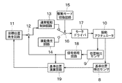
図4は振動アクチュエータ10のブロック回路構成図であり、フィードバック制御系が構成されている。目標位置発生回路11の出力は、減算器12を介して通常駆動制御回路13に接続されている。通常駆動制御回路13の出力と振動発生回路14の出力とは、駆動モード切換回路15によって駆動される切換器16により択一的に選択され、モータドライバ17を介し振動アクチュエータ10に接続されている。振動アクチュエータ10の出力は、基準位置検出センサ8、位置検出センサ9に並列的に接続され、位置検出センサ9の出力は信号処理回路18を経て、基準位置演算回路19に接続されると同時に減算器12にフィードバックされている。また、基準位置検出センサ8の出力は基準位置演算回路19に接続され、基準位置演算回路19の出力は目標位置発生回路11に接続されている。
FIG. 4 is a block circuit configuration diagram of the
通常のレンズ群3の駆動動作を行う場合には、目標位置発生回路11は振動アクチュエータ10が向かうべき目標位置を指示し、振動アクチュエータ10の位置は位置検出センサ9により検出され、信号処理回路18により所望の信号に変換される。例えば、位置検出センサ9の出力がパルス信号の場合に、これを信号処理回路18で計数することにより、振動アクチュエータ10の現在位置を検出することが可能である。減算器12は目標位置発生回路11と信号処理回路18のそれぞれの位置信号とから位置偏差信号を生成する。
When performing a normal driving operation of the
この位置偏差信号は通常駆動制御回路13に入力され、通常駆動制御回路13は偏差値がゼロとなるように所望の電圧・電流に変換した駆動信号をモータドライバ17に送信し、振動アクチュエータ10を駆動する。基準位置演算回路19は信号処理回路18が出力する位置情報と基準位置検出センサ8が出力する基準位置情報から、レンズ群3の位置情報の絶対値化を行う。この基準位置検出動作は機器の電源投入直後の起動時に行うことが一般的である。
This position deviation signal is input to the normal
振動アクチュエータ10により異物除去を行う場合には、駆動モード切換回路15は切換器16を介して通常駆動制御回路13との接続を切断し、振動発生回路14の出力をモータドライバ17に接続する。振動発生回路14は振動子6に対して異物除去に適した励振をするための定在波を発生する。
When removing the foreign matter by the
図5は実施例1の異物除去振動動作のフローチャート図である。 FIG. 5 is a flowchart of the foreign matter removing vibration operation of the first embodiment.
(ステップS11)装置の電源投入後に、駆動モード切換回路15により切換器16を介して、振動発生回路14の出力をモータドライバ17に接続し駆動モードの切換えを行い、異物除去駆動モードにする。
(Step S11) After turning on the power of the apparatus, the drive
(ステップS12)振動発生回路14は前述した定在波を発生させることで、振動アクチュエータ10は振動により振動子6、スライダ7、レンズ群3に付着した異物を除去する。その際に、定在波の周期電圧を断続的に加えることで、駆動周波数よりも低い周波数の振動を擬似的に発生させることが可能である。これにより異物除去を効率的に行うことができる。
(Step S12) The
(ステップS13)駆動モード切換回路15により、通常駆動制御回路13の出力をモータドライバ17に接続し、駆動モードをフィードバック制御による通常駆動モードに切換える。
(Step S13) The drive
(ステップS14)通常駆動により振動アクチュエータ10を駆動し、レンズ群3の基準位置の検出動作を行う。基準位置検出センサ8がフォトインタラプタの場合に、フォトインタラプタの出力のハイレベルとローレベルの切換わりを検出するように、振動アクチュエータ10を光軸方向に移動させる。この際に、振動アクチュエータ10の位置が基準位置検出センサ8から遠い場合は、基準位置検出センサ8まで推進動作中に摺動動作を兼ねることが可能である。つまり、可動部にブラシ等の異物除去部材を設置すれば、摺動により異物を払うこともできる。
(Step S14) The
(ステップS15)基準位置検出センサ8の出力信号からレンズ群3の基準位置を検出及び算出し、レンズ群3の位置を絶対値化する。
(Step S15) The reference position of the
上述したように、基準位置検出の動作前に異物除去振動駆動を行うことで、スライダ7や振動子6、レンズ群3に付着した塵埃を振るい落とすことが可能であり、通常動作移行後の不具合を改善することが可能である。更に、異物除去のための摺動動作を行う必要がなく、短時間で異物を除去できる。
As described above, by performing the foreign substance removal vibration drive before the reference position detection operation, it is possible to shake off the dust adhering to the
図6は実施例2の光学機器の断面図を示し、実施例1と同等の部材は同じ符号を付している。 FIG. 6 is a cross-sectional view of the optical apparatus according to the second embodiment, and members equivalent to those in the first embodiment are denoted by the same reference numerals.
固定鏡筒1には振動子6、スライダ7から成る振動アクチュエータ10の磨耗粉や塵埃を吸着するための吸着材21が設けられている。これにより、異物除去振動動作後に振るい落とされた塵埃が、再び振動アクチュエータ10やレンズ群3に付着することを防止することができる。なお、吸着材21を用いることで、異物が再び付着することを軽減することもできる。
The fixed
図7は実施例2の異物除去振動動作のフローチャート図である。 FIG. 7 is a flowchart of the foreign substance removal vibration operation of the second embodiment.
(ステップS21)装置の電源投入後に、駆動モードの切換えを行い異物除去駆動モードにする。 (Step S21) After the apparatus is powered on, the drive mode is switched to the foreign matter removal drive mode.
(ステップS22)振動発生回路14から定在波を発生させることで、振動アクチュエータ10により異物を除去する。その際に、定在波の周期電圧を断続的に加えることで、駆動周波数よりも低い周波数の振動を擬似的に発生させることが可能である。これにより異物除去を効率的に行うことができる。
(Step S <b> 22) A standing wave is generated from the
(ステップS23)振動アクチュエータに定在波と進行波を周期的に印加するために、駆動モード切換回路15により、通常駆動制御回路13と振動発生回路14への接続を周期的に切換える。切換周期は装置や移動部の共振周波数、或いは付着している異物の大きさを加味して設定するとよい。
(Step S23) In order to periodically apply the standing wave and the traveling wave to the vibration actuator, the drive
(ステップS24)被写体方向に振動アクチュエータ10を断続的に駆動しながら、基準位置検出の検出を行う。その際に、駆動可能な端位置まで移動することにより、異物除去部材による異物除去を兼ねた摺動動作が可能である。また、機構端に突き当て動作を行うようにすれば、突き当ての衝撃による異物除去も可能である。
(Step S24) The reference position detection is detected while intermittently driving the
(ステップS25)撮像面方向に振動アクチュエータ10を駆動しながら、レンズ群3の基準位置検出の検出を行う。この際にも、駆動可能な端位置まで移動することにより、異物除去のための摺動動作を兼ねることができる。
(Step S25) The reference position detection of the
(ステップS26)通常駆動モードにより振動アクチュエータ10を駆動し、基準位置の検出動作を行う。
(Step S26) The
(ステップS27)基準位置検出センサ8の出力信号から基準位置を検出及び算出し、レンズ群3の位置を絶対値化する。
(Step S27) The reference position is detected and calculated from the output signal of the reference
上述したように、基準位置の検出動作前或いは基準位置の検出動作中に異物除去振動駆動を行うことで、スライダ7や振動子6、レンズ群3に付着した塵埃を振るい落とすことが可能であり、通常駆動モードへの移行後の不具合を改善することが可能である。また、振動アクチュエータ10は基準位置検出と摺動による異物除去動作を兼ねることで、短時間かつ効果的に異物除去を実現できる。
As described above, it is possible to shake off dust adhering to the
1 固定鏡筒
2 レンズホルダ
3 レンズ群
6 振動子
7 スライダ
8 基準位置検出センサ
9 位置検出センサ
10 振動アクチュエータ
11 目標位置発生回路
12 減算器
13 通常駆動制御回路
14 振動発生回路
15 駆動モード切換回路
16 切換器
17 モータドライバ
18 信号処理回路
19 基準位置演算回路
21 吸着材
DESCRIPTION OF
Claims (6)
前記基準位置検出センサによる前記レンズ群の基準位置の検出動作前に、前記振動子に定在波の周期電圧を断続的に印加する異物除去振動動作を行うことを特徴とする光学機器。 Has a stator in contact with the vibrator and the vibrator generates vibrations, and a vibration actuator for moving the lens unit in the optical axis direction by applying a periodic voltage to the oscillator, the reference position of the lens group in the optical component must a reference position sensor for detecting a,
Optical apparatus, wherein said prior detection operation of the reference position of the lens group by the reference position detecting sensor, to perform a foreign matter removal oscillating motion intermittently applying a periodic voltage of the standing wave in the vibrator.
Priority Applications (1)
| Application Number | Priority Date | Filing Date | Title |
|---|---|---|---|
| JP2007058493A JP5164397B2 (en) | 2007-03-08 | 2007-03-08 | Vibration actuator and optical apparatus including the vibration actuator |
Applications Claiming Priority (1)
| Application Number | Priority Date | Filing Date | Title |
|---|---|---|---|
| JP2007058493A JP5164397B2 (en) | 2007-03-08 | 2007-03-08 | Vibration actuator and optical apparatus including the vibration actuator |
Publications (3)
| Publication Number | Publication Date |
|---|---|
| JP2008228366A JP2008228366A (en) | 2008-09-25 |
| JP2008228366A5 JP2008228366A5 (en) | 2010-04-08 |
| JP5164397B2 true JP5164397B2 (en) | 2013-03-21 |
Family
ID=39846334
Family Applications (1)
| Application Number | Title | Priority Date | Filing Date |
|---|---|---|---|
| JP2007058493A Expired - Fee Related JP5164397B2 (en) | 2007-03-08 | 2007-03-08 | Vibration actuator and optical apparatus including the vibration actuator |
Country Status (1)
| Country | Link |
|---|---|
| JP (1) | JP5164397B2 (en) |
Families Citing this family (5)
| Publication number | Priority date | Publication date | Assignee | Title |
|---|---|---|---|---|
| KR101063047B1 (en) * | 2010-06-23 | 2011-09-07 | 엘지이노텍 주식회사 | Camera module equipped with MEMs actuator and driving method thereof |
| JP5882796B2 (en) * | 2011-03-31 | 2016-03-09 | キヤノン株式会社 | Driving method for vibrating body, vibrating device, driving device having the vibrating device, and optical apparatus |
| JP5885552B2 (en) * | 2012-03-21 | 2016-03-15 | キヤノン株式会社 | Vibration device, drive device having the vibration device, and optical apparatus |
| JP6579207B2 (en) * | 2018-03-28 | 2019-09-25 | 株式会社ニコン | Vibration wave motor, lens barrel and camera |
| DE102023136551A1 (en) * | 2023-12-22 | 2025-06-26 | Tdk Electronics Ag | Optical arrangement and method for operating an optical arrangement |
Family Cites Families (2)
| Publication number | Priority date | Publication date | Assignee | Title |
|---|---|---|---|---|
| JP2006197698A (en) * | 2005-01-12 | 2006-07-27 | Canon Inc | Control device and control method for vibration actuator |
| JP2007017700A (en) * | 2005-07-07 | 2007-01-25 | Olympus Imaging Corp | Lens barrel and imaging device |
-
2007
- 2007-03-08 JP JP2007058493A patent/JP5164397B2/en not_active Expired - Fee Related
Also Published As
| Publication number | Publication date |
|---|---|
| JP2008228366A (en) | 2008-09-25 |
Similar Documents
| Publication | Publication Date | Title |
|---|---|---|
| JP5164397B2 (en) | Vibration actuator and optical apparatus including the vibration actuator | |
| JP6460833B2 (en) | Vibrating body, driving method of vibrating body, vibration type driving device, dust removing device, and imaging device | |
| JP2008253078A (en) | Electromechanical transducer, vibration actuator, drive device for vibration actuator, lens barrel and camera | |
| US9823543B2 (en) | Driver of vibrator, method of driving the same, lens driver, vibration device, and imaging device | |
| US7808153B2 (en) | Inertial drive actuator | |
| JP5309719B2 (en) | Vibration actuator, lens barrel and camera including the same | |
| JP4804040B2 (en) | Impact drive actuator | |
| US8482182B2 (en) | Driving apparatus, optical apparatus, and driving signal control circuit | |
| JP2016082867A5 (en) | Driving method of vibration type actuator, control method of driving device, driving device, imaging device and device | |
| JP2008197220A (en) | Lens barrel driving device | |
| JP2009240043A (en) | Drive controller of vibrating actuator, lens barrel equipped with the same, camera, and drive control method of the vibrating actuator | |
| JP2017034758A (en) | Vibrating actuator control device and control method thereof, vibration device, replacement lens, imaging device, and automatic stage | |
| JPWO2007108466A1 (en) | Vibrator, vibration actuator, lens barrel, camera system, and vibration actuator driving method | |
| JP6305026B2 (en) | Vibration type driving device and operation device using the same | |
| JP2012227988A (en) | Vibration type linear actuator and optical apparatus using the same | |
| CN111213313A (en) | Vibration wave motor and optical equipment | |
| JP5273915B2 (en) | Vibration type linear drive device and camera lens | |
| JP5591000B2 (en) | Drive device and control method thereof | |
| CN102714475B (en) | Drive control device and drive control method for vibration wave drive device | |
| JP2012023884A (en) | Photographing device | |
| JP4634174B2 (en) | Ultrasonic motor and electronic device using the same | |
| JP2000023475A (en) | Vibration actuator device | |
| JP5978646B2 (en) | Vibration wave motor, lens barrel, camera, and vibration wave motor control method | |
| JP2006203993A (en) | Control apparatus and control method | |
| JP2006197698A (en) | Control device and control method for vibration actuator |
Legal Events
| Date | Code | Title | Description |
|---|---|---|---|
| A521 | Written amendment |
Free format text: JAPANESE INTERMEDIATE CODE: A523 Effective date: 20100222 |
|
| A621 | Written request for application examination |
Free format text: JAPANESE INTERMEDIATE CODE: A621 Effective date: 20100222 |
|
| RD01 | Notification of change of attorney |
Free format text: JAPANESE INTERMEDIATE CODE: A7421 Effective date: 20100302 |
|
| RD01 | Notification of change of attorney |
Free format text: JAPANESE INTERMEDIATE CODE: A7421 Effective date: 20100630 |
|
| A977 | Report on retrieval |
Free format text: JAPANESE INTERMEDIATE CODE: A971007 Effective date: 20120229 |
|
| A131 | Notification of reasons for refusal |
Free format text: JAPANESE INTERMEDIATE CODE: A131 Effective date: 20120313 |
|
| A521 | Written amendment |
Free format text: JAPANESE INTERMEDIATE CODE: A523 Effective date: 20120514 |
|
| TRDD | Decision of grant or rejection written | ||
| A01 | Written decision to grant a patent or to grant a registration (utility model) |
Free format text: JAPANESE INTERMEDIATE CODE: A01 Effective date: 20121211 |
|
| A61 | First payment of annual fees (during grant procedure) |
Free format text: JAPANESE INTERMEDIATE CODE: A61 Effective date: 20121218 |
|
| FPAY | Renewal fee payment (event date is renewal date of database) |
Free format text: PAYMENT UNTIL: 20151228 Year of fee payment: 3 |
|
| R151 | Written notification of patent or utility model registration |
Ref document number: 5164397 Country of ref document: JP Free format text: JAPANESE INTERMEDIATE CODE: R151 |
|
| FPAY | Renewal fee payment (event date is renewal date of database) |
Free format text: PAYMENT UNTIL: 20151228 Year of fee payment: 3 |
|
| LAPS | Cancellation because of no payment of annual fees |