JP5164207B2 - Optical fiber wiring guide - Google Patents
Optical fiber wiring guide Download PDFInfo
- Publication number
- JP5164207B2 JP5164207B2 JP2008135226A JP2008135226A JP5164207B2 JP 5164207 B2 JP5164207 B2 JP 5164207B2 JP 2008135226 A JP2008135226 A JP 2008135226A JP 2008135226 A JP2008135226 A JP 2008135226A JP 5164207 B2 JP5164207 B2 JP 5164207B2
- Authority
- JP
- Japan
- Prior art keywords
- optical fiber
- guide
- base
- fiber wiring
- ceiling
- Prior art date
- Legal status (The legal status is an assumption and is not a legal conclusion. Google has not performed a legal analysis and makes no representation as to the accuracy of the status listed.)
- Active
Links
Images


Landscapes
- Details Of Indoor Wiring (AREA)
- Electric Cable Arrangement Between Relatively Moving Parts (AREA)
- Light Guides In General And Applications Therefor (AREA)
Description
本発明は、光ファイバの配線に供する光ファイバ配線ガイドに関する。 The present invention relates to an optical fiber wiring guide for use in optical fiber wiring.
光ファイバコードの配線を行うための光ファイバ配線ガイドの従来技術として、例えば、特許文献1(特開2000−224730号,発明の名称:ケーブル保護材)が開示されている。この従来技術のケーブル保護材は、長さの短いケーブル保護枠体を多数個にわたり連結して湾曲自在に形成したものである。 As a prior art of an optical fiber wiring guide for wiring an optical fiber cord, for example, Patent Document 1 (Japanese Patent Laid-Open No. 2000-224730, title of invention: cable protection material) is disclosed. This prior-art cable protection material is formed by connecting a large number of short cable protection frames and bending them freely.
特許文献1に記載のケーブル保護材は、特許文献1の図1,図6でも示すように、3次元方向に湾曲させるため、球と上下二カ所の孔とにより連結部を構成したものであり、構造が複雑で製造に手間を要するものであった。また、この連結部の上下二カ所の孔に球を入れるためには上下二カ所の孔が移動できるように孔の形成部に弾性を持たせる必要があり、換言すれば、強い力が加わると上下二カ所の孔から球が抜け易いということでもあり、連結部は強度の点で問題もあった。
また、特許文献1に記載のケーブル保護材のケーブル保護枠体は一枚の底板部、二枚の側板部を組み立てる必要があり、この点でも製造に手間を要するという問題もあった。
As shown in FIGS. 1 and 6 of
Further, the cable protection frame body of the cable protection material described in
さらにまた、ケーブル保護枠体は一枚の底板部、左右別構造となる二枚の側板部を有するものであって部品点数が多くなり、また多数のケーブル保護枠体を湾曲可能に連結できるようにするため機械精度を大幅に向上させる必要もあり、これら点から大幅なコスト増大要因ともなっていた。
さらにまた、二枚の側板部内に複数のケーブルを配置した場合であってケーブル本数が多くなると、ケーブルが見分けにくくなり、後に再接続を行うような場合に使い勝手が悪いことがあった。
Furthermore, the cable protection frame has one bottom plate part and two side plate parts that have a separate left and right structure, so that the number of parts is increased and a large number of cable protection frame bodies can be connected to bendable. Therefore, it is necessary to greatly improve the machine accuracy, and from these points, the cost has been greatly increased.
Furthermore, when a plurality of cables are arranged in the two side plate portions and the number of cables increases, it becomes difficult to distinguish the cables, and there are cases where the usability is poor when reconnection is performed later.
そこで、本発明は上記の課題を解決するためになされたものであり、その目的は、簡易かつ安価な構造で、機械的強度を増すとともに整線能力も向上させた光ファイバ配線ガイドを提供することにある。 Accordingly, the present invention has been made to solve the above-mentioned problems, and an object of the present invention is to provide an optical fiber wiring guide having a simple and inexpensive structure with increased mechanical strength and improved wire-shaping capability. There is.
本発明の請求項1に係る光ファイバ配線ガイドは、
同一形状に形成された板状のベース部を複数連結して屈曲可能に形成し、これらベース部それぞれに立設されるガイド部内に光ファイバを配置して整線する光ファイバ配線ガイドであって、
ベース部は、板状の本体ベースと、本体ベース平面に対して垂直に立設される軸部と、本体ベース平面に対して垂直な孔である軸支部と、本体ベースに設けられてガイド部を係止させる凹状の係止部と、係止部内に形成される係止孔と、を有し、
ガイド部は、底面部と、底面部下側から突出する係止突起と、底面部の両横側から上側へ立設する二個の側壁部と、二個の側壁部からそれぞれ突設する二個の天井部と、二個の天井部の対向部に形成される開口部と、を有し、
ベース部の係止孔にガイド部の係止突起が挿入されるとともにベース部の凹状の係止部内に底面部が嵌め込まれてベース部にガイド部が連結固定され、かつ、ベース部の軸支部に対して他のベース部の軸部を軸着して複数個に渡り連結したものであることを特徴とする。
An optical fiber wiring guide according to
An optical fiber wiring guide in which a plurality of plate-like base portions formed in the same shape are connected to be bent so that an optical fiber is arranged in a guide portion standing on each of the base portions to adjust the line. ,
The base portion includes a plate-like main body base, a shaft portion standing perpendicular to the main body base plane, a shaft support portion that is a hole perpendicular to the main body base plane, and a guide portion provided on the main body base. A concave locking portion that locks the locking portion, and a locking hole formed in the locking portion ,
The guide part includes a bottom part, a locking projection protruding from the bottom part of the bottom part, two side walls standing up from both sides of the bottom part, and two protruding from the two side parts. And an opening formed at a facing portion of the two ceiling portions,
The locking protrusion of the guide portion is inserted into the locking hole of the base portion, the bottom surface portion is fitted into the concave locking portion of the base portion, the guide portion is connected and fixed to the base portion, and the shaft support portion of the base portion characterized in der Rukoto the concatenation over multiple and pivotally attached to the shaft portion of the other of the base portion with respect.
また、本発明の請求項2に係る光ファイバ配線ガイドは、
請求項1に記載の光ファイバ配線ガイドにおいて、
前記ベース部は連結される他のベース部の当接部と当接して移動を拘束する拘束部を有し、複数連結したベース部は、当接部が拘束部に接しつつ屈曲させた場合に、曲率半径が最低曲率半径R以上であるように維持されることを特徴とする。
An optical fiber wiring guide according to claim 2 of the present invention is
In the optical fiber wiring guide according to
The base part has a restraining part that restrains movement by coming into contact with an abutting part of another base part to be coupled, and a plurality of connected base parts are bent when the abutting part is in contact with the restraining part. The curvature radius is maintained so as to be equal to or greater than the minimum curvature radius R.
また、本発明の請求項3に係る光ファイバ配線ガイドは、
請求項1または請求項2に記載の光ファイバ配線ガイドにおいて、
前記二個の天井部の対向部は、開口部へ向かうにつれて先細ることを特徴とする。
An optical fiber wiring guide according to claim 3 of the present invention is
In the optical fiber wiring guide according to
Opposing portions of the two ceiling section is characterized Rukoto tapered toward the opening.
また、本発明の請求項4に係る光ファイバ配線ガイドは、
請求項1〜請求項3の何れか一項に記載の光ファイバ配線ガイドにおいて、
前記ガイド部は底面部から天井部までの高さが異なる複数種類のガイド部とし、
底面部と最も低い天井部との間の経路、および、高さが異なるとともに二個の隣接する天井部による経路、という複数経路の間にそれぞれ光ファイバを配置して整線することを特徴とする。
An optical fiber wiring guide according to claim 4 of the present invention is
In the optical fiber wiring guide according to any one of
The guide part is a plurality of types of guide parts having different heights from the bottom part to the ceiling part,
Path between the lowest ceiling and bottom portion, and wherein the wire arranging to Rukoto each arranged optical fibers between the multi-path pathway by ceiling, that height of two adjacent with different And
以上のような本発明によれば、簡易かつ安価な構造で、機械的強度を増すとともに整線能力も向上させた光ファイバ配線ガイドを提供することができる。 According to the present invention as described above, it is possible to provide an optical fiber wiring guide that has a simple and inexpensive structure, has increased mechanical strength, and improved wire-shaping ability.
本発明を実施するための最良の形態について図に基づいて以下に説明する。図1は本形態の光ファイバ配線ガイドの斜視外観図である。
光ファイバ配線ガイド10は、多数のガイド単体が連結されて屈曲可能に形成されたものである。このガイド単体とは、一個のベース部100に一個のガイド部200を立設させた構造体である。光ファイバ配線ガイド10は、これらベース部100それぞれに立設されるガイド部200内に配置された光ファイバ(図示せず)を整線する機能を有する。
The best mode for carrying out the present invention will be described below with reference to the drawings. FIG. 1 is a perspective external view of an optical fiber wiring guide of this embodiment.
The optical
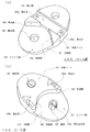
続いて各部の詳細について説明する。まず、ベース部100について図を参照しつつ説明する。図2はベース部の構造図であり、図2(a)は斜視平面図、図2(b)は斜視底面図である。図3は、ベース部の構造図であり、図3(a)は平面図、図3(b)は側面図、図3(c)はA−A線断面図、図3(d)は底面図である。 Next, details of each unit will be described. First, the base unit 100 will be described with reference to the drawings. 2A and 2B are structural views of the base portion. FIG. 2A is a perspective plan view, and FIG. 2B is a perspective bottom view. 3A and 3B are structural views of the base portion. FIG. 3A is a plan view, FIG. 3B is a side view, FIG. 3C is a cross-sectional view taken along line AA, and FIG. FIG.
ベース部100は、図2,図3で示すように、本体ベース101、スライド面102、軸支部103、拘束部104、当接部105、係止部106、スライド面107、軸部108、拘束部109、当接部110を備えている。ベース部100は、弾性を有する合成樹脂などによりこれら本体ベース101、スライド面102、軸支部103、拘束部104、当接部105、係止部106、スライド面107、軸部108、拘束部109、当接部110が一体に形成されている。
As shown in FIGS. 2 and 3, the base portion 100 includes a main body base 101, a slide surface 102, a shaft support portion 103, a restraint portion 104, a contact portion 105, a locking portion 106, a
本体ベース101は、側面から見て板状であり、平面から見て長円状の基礎ベース部材である。この本体ベース101は各種の構成が一体に形成される。図2(a)が表側(平面)であり、図2(b)が裏側(底面)である。
スライド面102は、本体ベース101に形成される水平面である。
軸支部103は、スライド面102に形成された貫通孔である。軸支部103は、スライド面102に対して垂直な孔である。
The main body base 101 is a plate-like base base member viewed from the side, and is an oval base base member viewed from the plane. The main body base 101 is integrally formed with various configurations. 2A is the front side (plane), and FIG. 2B is the back side (bottom surface).
The slide surface 102 is a horizontal plane formed on the main body base 101.
The shaft support portion 103 is a through hole formed in the slide surface 102. The shaft support 103 is a hole perpendicular to the slide surface 102.
拘束部104は、スライド面102の周囲にて立設される湾曲した側壁である。
当接部105は、後述するがスライド面102下方の側面部が該当する。
係止部106は、ガイド部200の取付位置を決定する溝である。ガイド部200を固着するための係止孔106aが形成されている。
The restraining portion 104 is a curved side wall that stands up around the slide surface 102.
The contact portion 105 corresponds to a side portion below the slide surface 102 as described later.
The locking portion 106 is a groove that determines the mounting position of the
スライド面107は、スライド面102が形成された表側とは反対の裏側にて本体ベース101に形成される水平面である。スライド面107とスライド面102とは、平行面である。
軸部108は、スライド面107に対して垂直に形成された軸部である。この軸部は中心軸に貫通孔が形成されるとともに、切れ込み部108aも形成されており、軸部108を軸支部103に入れる際に軸部108を小さくして嵌着し易いように配慮している。
拘束部109は、スライド面107の周囲にて立設される湾曲した側壁である。
当接部110は、後述するがスライド面107下方の側面部が該当する。
The
The shaft portion 108 is a shaft portion formed perpendicular to the
The restraining
The contact part 110 corresponds to a side part below the
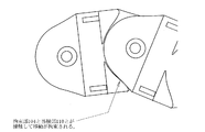
続いて、ベース部100の連結について図を参照しつつ説明する。図4は連結されたベース部の移動拘束を説明する説明図である。図5は光ファイバ配線ガイドの連結構造およびその連結構造の曲率半径を説明する説明図である。
ベース部100の軸支部103に対して、他のベース部の軸部108が嵌め込まれて連結される。この場合に平行面であるスライド面102とスライド面107とが接するため円滑に回転自在となるが、図4で示すように、拘束部104と当接部110が接触してある角度を超える回転ができないように移動が拘束される。そして、裏側の拘束部109と当接部105とも接触してある角度を超える回転ができないように移動が拘束される。これら角度は同じに設定され、表裏両側で同時に移動が拘束されるようにしており、拘束が確実になされるようにしている。光ファイバは曲率半径が小さくなる、つまりカーブがきつくなるにつれて伝送損失が生じるが、上記した移動拘束により、図5に示すように曲率半径が最低曲率半径Rを下回らないようにして、きついカーブを形成しないようにし、光ファイバが過剰に折り曲げられないようにする。このような最低曲率半径としてはR=30mmが選択される。なお、最低曲率半径Rは30mmを下回らなければよいというものであり、例えばR=35mmというように光ファイバに伝送損失が生じる曲率半径よりも緩やかになるように余裕を持たせた最低曲率半径を選択しても良い。
Next, the connection of the base unit 100 will be described with reference to the drawings. FIG. 4 is an explanatory view for explaining the movement restraint of the connected base portions. FIG. 5 is an explanatory view for explaining the connection structure of the optical fiber wiring guide and the radius of curvature of the connection structure.
The shaft portion 108 of the other base portion is fitted and connected to the shaft support portion 103 of the base portion 100. In this case, the slide surface 102 and the
また、軸支部103に軸部108を嵌め込む構造であるため、軸支部103および軸部108の中心軸(回転軸)方向に不要な力が加わると連結が外れるおそれがあるが、軸支部103および軸部108の半径方向の力に対しては十分に強い構造体となる。この光ファイバ配線ガイド10は後述するが回転時など半径方向に力が加わることが多いが、十分な強度を確保しているため特に連結が外れることなく移動することができる。したがって、光ファイバ配線ガイド10は、移動により折れ曲がったとしても、内部にある光ファイバの整線を維持し、また、過剰に折れ曲がる事態を防止する。
Further, since the shaft portion 108 is fitted into the shaft support portion 103, there is a possibility that the connection is released when an unnecessary force is applied in the direction of the central axis (rotation axis) of the shaft support portion 103 and the shaft portion 108. In addition, the structure is sufficiently strong against the radial force of the shaft portion 108. As will be described later, the optical
続いてガイド部200について説明する。図6はガイド部の構造図であり、図6(a)は低背型のガイド部の正面図、図6(b)は低背型のガイド部の側面図、図6(c)は高背型のガイド部の正面図、図6(d)は高背型のガイド部の側面図である。まず、低背型のガイド部200について説明する。
Next, the
ガイド部200は、図6(a),(b)で示すように、底面部201、側面部202、天井部203、開口部204を備える。ガイド部200は、弾性を有する合成樹脂などにより底面部201、二個の側面部202、二個の天井部203が一体に形成されている。
底面部201は長板であり、下面には係止突起201aが一体に形成されている。また、底面部201は、ベース部100の係止部106と同じ形状であり、この係止部106内に嵌め込まれ、係止突起201aが係止孔106aに固定されて取り付けられるようになされている。
側面部202は、底面部201の側面に連接された状態で立設される。側面部202は底面部201の両側で二個形成される。
The
The bottom surface portion 201 is a long plate, and a locking projection 201a is integrally formed on the bottom surface. Further, the bottom surface portion 201 has the same shape as the locking portion 106 of the base portion 100, and is fitted into the locking portion 106 so that the locking projection 201a is fixedly attached to the locking hole 106a. Yes.
The side surface portion 202 is erected in a state where it is connected to the side surface of the bottom surface portion 201. Two side parts 202 are formed on both sides of the bottom part 201.
天井部203は、側面部202から突設される。二個の側面部202に対してそれぞれ二個の天井部203が形成される
開口部204は、二個の天井部203の対向部に形成される孔である。二個の天井部203は、図6(a)でも明らかなように開口部204へ向かうにつれて先細るようになされており、外から中へは光ファイバを入れやすいが、中から外へは光ファイバを出しにくいように配慮している。なお、光ファイバをガイド部200の中から引き出すときは開口部204を押し広げて拡開すれば良く、整線作業を容易にしている。
The ceiling part 203 protrudes from the side part 202. Two ceiling portions 203 are formed for each of the two side surface portions 202. The opening portion 204 is a hole formed in an opposing portion of the two ceiling portions 203. As clearly shown in FIG. 6A, the two ceiling portions 203 taper toward the opening portion 204, and it is easy to put an optical fiber from the outside to the inside. Consideration is given to make it difficult to pull out the fiber. Note that when the optical fiber is pulled out from the
なお、図6(c),(d)で示すガイド部200は、高背型のガイド部200である。このガイド部200は二個の側面部202が長い点以外は先に説明した低背型のガイド部200と同じ構成であり、重複する説明を省略する。
6C and 6D is a high-
続いてガイド部200により形成される経路について図を参照しつつ説明する。図7,図8はガイド部により形成される経路の説明図である。図7に示すように高背型のガイド部200と低背型のガイド部200を準備する。例えば図1で示したように高背型と低背型とのガイド部200を交互に配置したものとする。ここで光ファイバ配線ガイド10が直線状であるとしたとき、図7に示すように、開口面側から見ると底面部201、低背型のガイド部の天井部203および両側の側面部202により第一経路301が形成され、また、低背型のガイド部200の天井部203、高背型のガイド部の天井部203および両側の側面部202により第二経路302が形成される。このような二経路を用いることでルート分け配線が容易になる。
Next, a path formed by the
なお、このような経路形成は高背型と低背型とのガイド部200を交互に配置するのみならず、例えば高背型のガイド部200を続けて二個配置し、次に低背型のガイド部200を続けて二個配置し、以下同様に二個づつ並べて高背型と低背型とのガイド部200を交互に配置するようにしても本発明の実施は可能である。高背型と低背型とのガイド部200の配置は距離を空けすぎない限り適宜選択が可能である。
In addition, such a path is formed not only by alternately arranging the high-profile and low-
また、他の例について説明する。図8で示すように低背型のガイド部200、中背型のガイド部200、高背型のガイド部200をそれぞれ準備する。例えば低背型→中背型→高背型という順序でガイド部200を繰り返し配置したものとする。ここで光ファイバ配線ガイドが直線状であるとした場合、開口面側から見ると底面部201、低背型のガイド部の天井部203および両側の側面部202により第一経路301が形成され、低背型のガイド部200の天井部203、中背型のガイド部の天井部203および両側の側面部202により第二経路302が形成され、中背型のガイド部200の天井部203、高背型のガイド部の天井部203および両側の側面部202により第三経路303が形成される。このような三経路を用いることでルート分け配線がさらに容易になる。
Another example will be described. As shown in FIG. 8, a low
なお、このような経路形成は低背型、中背型、高背型の順序でガイド部200を繰り返し配置するのみならず、例えば低背型のガイド部200を続けて二個配置し、次に中背型のガイド部200を続けて二個配置し、次に高背型のガイド部200を続けて二個配置し、以下同様に二個づつ並べて低背型、中背型、高背型のガイド部200を繰り返し配置するようにしても本発明の実施は可能である。低背型、中背型、高背型のガイド部200の配置は距離を空けすぎない限り適宜選択が可能である。
In addition, such a path is formed not only by repeatedly arranging the
続いて、光ファイバ配線ガイドの使用例である光パッチパネルについて図を参照しつつ説明する。図9は収納時の光パッチパネルの説明図、図10は引き出し時の光パッチパネルの説明図である。
この光パッチパネル1は、例えば19インチラックなどに実装され、光ファイバケーブルを固定した状態でスライドできるようになされている。なお、この光パッチパネル1は、縦置きを前提としたものであるが、図示しないが横置き構成としても良い。
Next, an optical patch panel, which is an example of use of the optical fiber wiring guide, will be described with reference to the drawings. FIG. 9 is an explanatory diagram of the optical patch panel when stored, and FIG. 10 is an explanatory diagram of the optical patch panel when pulled out.
The
光パッチパネル1は、先に説明した本形態の光ファイバ配線ガイド10、パネル収容部、パネル本体30、クランプ部40、余長部50、アダプタパネル60、スライドレール70、ラック固定部80を備えている。このような光パッチパネル1に収納される光ファイバケーブルは、一例として、先端に48個のアダプタを備え、それぞれのアダプタに接続される光ファイバの単心コードを単心分岐部にて4本毎に集めて光ファイバの4心コード部とし、光ファイバの4心コード部をさらにケーブル分岐部にて全て集めて単線ケーブルとするような光ファイバケーブルであるものとして説明する。なお、他の形態の光ファイバケーブルであって良いことはいうまでもない。
The
パネル収容部20は、例えば、図9(a)の正面から見たときに略C字状の構造体である。
パネル本体30は、板状の部材であり、プラスチックや金属などの部材にて構成されている。パネル本体30はパネル収容部20内に収容されるようになされている。パネル本体30には、図示しないが光ファイバ配線ガイド10の両端を支持する支持部が設けられている。この支持部として、例えば、先に挙げた軸部や軸支部とすることで、光ファイバ配線ガイド10は、パネル本体30に対して回転移動や湾曲が可能に支持されることとなる。なお、これらのパネル収容部20およびパネル本体30の形状は、図9,図10で示したものに限定されるものでなく、各種形状を採用できる。
The panel accommodating part 20 is a substantially C-shaped structure when viewed from the front of FIG.
The panel main body 30 is a plate-like member, and is composed of a member such as plastic or metal. The panel body 30 is accommodated in the panel accommodating portion 20. Although not shown, the panel main body 30 is provided with a support portion that supports both ends of the optical
クランプ部40は、パネル本体30に固定され、光ファイバのケーブル分岐部をクランプする。光パッチパネル1の導入口へは一本の光ファイバケーブルが導入されることとなる。
そして本形態の光ファイバ配線ガイド10は、複数の4心コード部をそのガイド部200内に収納する。先に説明した複数経路部に分けて配置することでルート分け配線を実現し、整理を容易にしている。
The clamp part 40 is fixed to the panel body 30 and clamps the cable branching part of the optical fiber. One optical fiber cable is introduced into the introduction port of the
And the optical
余長部50は、4心コード部を巻き回して収容したものである。そして余長部50の周囲に単心分岐部を配置し、この単心分岐部から単心コードを引き出してアダプタ61にそれぞれ接続している。
アダプタパネル60は、これら48個のアダプタ61が連結固定されている。アダプタ61は、それぞれ図示しないプラグが接続されて光ファイバの接続を行う。
The extra length portion 50 is a portion in which the four-core cord portion is wound and accommodated. A single-core branch portion is disposed around the extra length portion 50, and a single-core cord is drawn from the single-core branch portion and connected to the
These 48
スライドレール70は、スライド機能を有するものであり、図9,図10に示すようにパネル収容部20とパネル本体30との間に介在して上下に連結される。このような構造ではパネル収容部20に対してパネル本体30がスライド可能に構成される。
ラック固定部80は光パッチパネル1を収容する19インチラック本体に固定される。
The
The
このような構成の光パッチパネル1は、通常時には図9(b)に示すようにラック本体に収容されている。そして、接続作業を行う場合に光パッチパネル1のパネル本体30を引き出すと、スライドレール70により滑らかにパネル本体30が引き出されて、図10に示すようにパネル本体30が引き出された状態となる。この引き出し時に光ファイバ配線ガイド10は図9のような曲がった状態から図10のような伸びた状態となるが光ファイバ配線ガイド10は全ての箇所で光ファイバに影響のないように緩やかな曲げ状態となっており、光ファイバに不用意な曲げを与えるおそれがない。さらに、光ファイバ配線ガイド10の自重や移動により生じる力が軸支部103と軸部108とに加わるが、この場合に軸方向には加わる力は少なく半径方向には大きな力が加わるというものであり、軸支部103と軸部108とではこられ力に十分抗するように支持できるため、抜けたりして整線が乱れたり過剰に曲がるようなおそれを低減している。
The
以上、本発明の光ファイバ配線ガイド10について説明した。なお、光ファイバ配線ガイド10は光パッチパネルのみならず、光配線盤、光配線箱など各種装置に適用することができる。
また、配線経路を複数形成する構成について説明したが、同じ高さのガイド部20のみを用いて一の経路の光ファイバ配線ガイド10とすることができる。本発明の光ファイバ配線ガイド10は一または複数の経路を選択形成できる点も従来にない優れた利点となっている。そして一のみの経路も低背型のガイド部200を採用する狭い経路、中背型のガイド部200を採用する中間広さの経路、高背型のガイド部200を採用する広い経路の選択も可能となっている。
また、光パッチパネル内に軸部や軸支部を設けることで光ファイバ配線ガイド10を光パッチパネルなどから取り外し可能として、配線作業を容易に行うことができる。
The optical
Moreover, although the structure which forms several wiring paths was demonstrated, it can be set as the optical
Further, by providing the shaft portion and the shaft support portion in the optical patch panel, the optical
10:光ファイバ配線ガイド
100:ベース部
101:本体ベース
102:スライド面
103:軸支部
104:拘束部
105:当接部
106:係止部
106a:係止孔
107:スライド面
108:軸部
108a:切れ込み部
109:拘束部
110:当接部
200:ガイド部
201:底面部
201a:係止突起
202:側面部
203:天井部
204:開口部
301:第一経路
302:第二経路
303:第三経路
20:パネル収容部
30:パネル本体
40:クランプ部
50:余長部
60:アダプタパネル
61:アダプタ
70:スライドレール
80:ラック固定部
DESCRIPTION OF SYMBOLS 10: Optical fiber wiring guide 100: Base part 101: Main body base 102: Slide surface 103: Shaft support part 104: Restraining part 105: Contact part 106: Locking part 106a: Locking hole 107: Slide surface 108: Shaft part 108a : Cut section 109: Restraining section 110: Contact section 200: Guide section 201: Bottom section 201 a: Locking protrusion 202: Side section 203: Ceiling section 204: Opening section 301: First path 302: Second path 303: Second Three paths 20: Panel housing part 30: Panel body 40: Clamp part 50: Extra length part 60: Adapter panel 61: Adapter 70: Slide rail 80: Rack fixing part
Claims (4)
ベース部は、板状の本体ベースと、本体ベース平面に対して垂直に立設される軸部と、本体ベース平面に対して垂直な孔である軸支部と、本体ベースに設けられてガイド部を係止させる凹状の係止部と、係止部内に形成される係止孔と、を有し、
ガイド部は、底面部と、底面部下側から突出する係止突起と、底面部の両横側から上側へ立設する二個の側壁部と、二個の側壁部からそれぞれ突設する二個の天井部と、二個の天井部の対向部に形成される開口部と、を有し、
ベース部の係止孔にガイド部の係止突起が挿入されるとともにベース部の凹状の係止部内に底面部が嵌め込まれてベース部にガイド部が連結固定され、かつ、ベース部の軸支部に対して他のベース部の軸部を軸着して複数個に渡り連結したものであることを特徴とする光ファイバ配線ガイド。 An optical fiber wiring guide in which a plurality of plate-like base portions formed in the same shape are connected to be bent so that an optical fiber is arranged in a guide portion standing on each of the base portions to adjust the line. ,
The base portion includes a plate-like main body base, a shaft portion standing perpendicular to the main body base plane, a shaft support portion that is a hole perpendicular to the main body base plane, and a guide portion provided on the main body base. A concave locking portion that locks the locking portion, and a locking hole formed in the locking portion ,
The guide part includes a bottom part, a locking projection protruding from the bottom part of the bottom part, two side walls standing up from both sides of the bottom part, and two protruding from the two side parts. And an opening formed at a facing portion of the two ceiling portions,
The locking protrusion of the guide portion is inserted into the locking hole of the base portion, the bottom surface portion is fitted into the concave locking portion of the base portion, the guide portion is connected and fixed to the base portion, and the shaft support portion of the base portion optical fiber routing guides, characterized in der Rukoto the concatenation over multiple and pivotally attached to the shaft portion of the other of the base portion with respect.
前記ベース部は連結される他のベース部の当接部と当接して移動を拘束する拘束部を有し、複数連結したベース部は、当接部が拘束部に接しつつ屈曲させた場合に、曲率半径が最低曲率半径R以上であるように維持されることを特徴とする光ファイバ配線ガイド。 In the optical fiber wiring guide according to claim 1,
The base part has a restraining part that restrains movement by coming into contact with an abutting part of another base part to be coupled, and a plurality of connected base parts are bent when the abutting part is in contact with the restraining part. An optical fiber wiring guide, wherein the curvature radius is maintained so as to be equal to or greater than the minimum curvature radius R.
前記二個の天井部の対向部は、開口部へ向かうにつれて先細ることを特徴とする光ファイバ配線ガイド。 In the optical fiber wiring guide according to claim 1 or 2,
The facing portions of two of the ceiling portion, the optical fiber routing guides, wherein Rukoto tapered toward the opening.
前記ガイド部は底面部から天井部までの高さが異なる複数種類のガイド部とし、
底面部と最も低い天井部との間の経路、および、高さが異なるとともに二個の隣接する天井部による経路、という複数経路の間にそれぞれ光ファイバを配置して整線することを特徴とする光ファイバ配線ガイド。 In the optical fiber wiring guide according to any one of claims 1 to 3 ,
The guide part is a plurality of types of guide parts having different heights from the bottom part to the ceiling part,
Path between the lowest ceiling and bottom portion, and wherein the wire arranging to Rukoto each arranged optical fibers between the multi-path pathway by ceiling, that height of two adjacent with different An optical fiber wiring guide .
Priority Applications (1)
| Application Number | Priority Date | Filing Date | Title |
|---|---|---|---|
| JP2008135226A JP5164207B2 (en) | 2008-05-23 | 2008-05-23 | Optical fiber wiring guide |
Applications Claiming Priority (1)
| Application Number | Priority Date | Filing Date | Title |
|---|---|---|---|
| JP2008135226A JP5164207B2 (en) | 2008-05-23 | 2008-05-23 | Optical fiber wiring guide |
Publications (2)
| Publication Number | Publication Date |
|---|---|
| JP2009284692A JP2009284692A (en) | 2009-12-03 |
| JP5164207B2 true JP5164207B2 (en) | 2013-03-21 |
Family
ID=41454534
Family Applications (1)
| Application Number | Title | Priority Date | Filing Date |
|---|---|---|---|
| JP2008135226A Active JP5164207B2 (en) | 2008-05-23 | 2008-05-23 | Optical fiber wiring guide |
Country Status (1)
| Country | Link |
|---|---|
| JP (1) | JP5164207B2 (en) |
Families Citing this family (6)
| Publication number | Priority date | Publication date | Assignee | Title |
|---|---|---|---|---|
| KR200455816Y1 (en) | 2011-01-19 | 2011-09-27 | 주식회사 명신이엔지 | Wiring Holder |
| JP6311199B2 (en) * | 2014-05-14 | 2018-04-18 | 日本通信電材株式会社 | Cable guide |
| TWI616131B (en) * | 2016-08-31 | 2018-02-21 | 川湖科技股份有限公司 | Cable management device |
| JP6894078B2 (en) * | 2017-05-01 | 2021-06-23 | 国立研究開発法人情報通信研究機構 | Optical fiber holder |
| US11137549B2 (en) * | 2019-10-25 | 2021-10-05 | Raytheon Company | Scalable and fully-adjustable multiple fiber holder |
| JP2023147781A (en) * | 2022-03-30 | 2023-10-13 | 住友電装株式会社 | Wire movable route regulating component and route regulating wire harness |
Family Cites Families (4)
| Publication number | Priority date | Publication date | Assignee | Title |
|---|---|---|---|---|
| JP3792063B2 (en) * | 1999-02-03 | 2006-06-28 | 日東工業株式会社 | Cable protector |
| DE20016363U1 (en) * | 2000-09-21 | 2001-01-18 | Igus Gmbh | Energy chain |
| DE10216043A1 (en) * | 2002-04-11 | 2003-10-23 | Kabelschlepp Gmbh | Line routing unit for the active routing of lines, cables or the like |
| JP2007057806A (en) * | 2005-08-24 | 2007-03-08 | Maspro Denkoh Corp | Wdm filter holder in optical fiber storing part of optical receiver |
-
2008
- 2008-05-23 JP JP2008135226A patent/JP5164207B2/en active Active
Also Published As
| Publication number | Publication date |
|---|---|
| JP2009284692A (en) | 2009-12-03 |
Similar Documents
| Publication | Publication Date | Title |
|---|---|---|
| JP5164207B2 (en) | Optical fiber wiring guide | |
| US11340417B2 (en) | Slidable fiber optic connection module with cable slack management | |
| CN107111092B (en) | Rotatable jumper cable holder | |
| US6944383B1 (en) | Cable management panel with sliding drawer and methods | |
| US9678295B2 (en) | Fiber optic cable module holder | |
| US7194181B2 (en) | Adapter block including connector storage | |
| WO2010126991A2 (en) | Fiber optic panels configured to retain fiber optic components in a depth space of a chassis | |
| US20100329621A1 (en) | Fiber Optic Cable Slack Storage Module | |
| JP2012120095A (en) | Optical module, and optical system | |
| CN205790896U (en) | A kind of equipment and the slot mechanism for grafting fiber optic cables plug | |
| KR101366810B1 (en) | Fiber optic cable connecting terminal box | |
| JP7281295B2 (en) | optical termination box | |
| US20130089297A1 (en) | Slidable fiber optic connection module with cable slack management | |
| JP3883113B2 (en) | Optical connection box cord extra length storage | |
| CN117826350B (en) | Plug-in butterfly-shaped optical cable and optical cable | |
| JP5052467B2 (en) | Optical distribution board | |
| JPH1048491A (en) | Terminal structure of optical cable with connector | |
| KR101237516B1 (en) | Ribbon unite | |
| JP4840572B2 (en) | Optical module and optical junction box | |
| JP2002267902A (en) | Terminal structure of optical cable with connector | |
| CN105826795A (en) | Equipment and slot mechanism used for plugging optical fiber cable plug | |
| KR20160123772A (en) | Optical cable connecting module and hybrid optical connecting system having the same | |
| JP2015215386A (en) | Optical wiring unit | |
| JP2007233268A (en) | Optical connector module, optical backplane, in-housing optical communication device, and optical connection method | |
| JP2006064736A (en) | Structure of excessive length storage part of optical fiber |
Legal Events
| Date | Code | Title | Description |
|---|---|---|---|
| A621 | Written request for application examination |
Free format text: JAPANESE INTERMEDIATE CODE: A621 Effective date: 20110510 |
|
| A977 | Report on retrieval |
Free format text: JAPANESE INTERMEDIATE CODE: A971007 Effective date: 20120813 |
|
| A131 | Notification of reasons for refusal |
Free format text: JAPANESE INTERMEDIATE CODE: A131 Effective date: 20121116 |
|
| A521 | Request for written amendment filed |
Free format text: JAPANESE INTERMEDIATE CODE: A523 Effective date: 20121129 |
|
| TRDD | Decision of grant or rejection written | ||
| A01 | Written decision to grant a patent or to grant a registration (utility model) |
Free format text: JAPANESE INTERMEDIATE CODE: A01 Effective date: 20121214 |
|
| A61 | First payment of annual fees (during grant procedure) |
Free format text: JAPANESE INTERMEDIATE CODE: A61 Effective date: 20121214 |
|
| FPAY | Renewal fee payment (event date is renewal date of database) |
Free format text: PAYMENT UNTIL: 20151228 Year of fee payment: 3 |
|
| R150 | Certificate of patent or registration of utility model |
Ref document number: 5164207 Country of ref document: JP Free format text: JAPANESE INTERMEDIATE CODE: R150 Free format text: JAPANESE INTERMEDIATE CODE: R150 |
|
| R250 | Receipt of annual fees |
Free format text: JAPANESE INTERMEDIATE CODE: R250 |
|
| R250 | Receipt of annual fees |
Free format text: JAPANESE INTERMEDIATE CODE: R250 |
|
| R250 | Receipt of annual fees |
Free format text: JAPANESE INTERMEDIATE CODE: R250 |
|
| R250 | Receipt of annual fees |
Free format text: JAPANESE INTERMEDIATE CODE: R250 |
|
| R250 | Receipt of annual fees |
Free format text: JAPANESE INTERMEDIATE CODE: R250 |
|
| R250 | Receipt of annual fees |
Free format text: JAPANESE INTERMEDIATE CODE: R250 |
|
| R250 | Receipt of annual fees |
Free format text: JAPANESE INTERMEDIATE CODE: R250 |
|
| R250 | Receipt of annual fees |
Free format text: JAPANESE INTERMEDIATE CODE: R250 |
|
| R250 | Receipt of annual fees |
Free format text: JAPANESE INTERMEDIATE CODE: R250 |