JP5163072B2 - Flow measuring device and program thereof - Google Patents
Flow measuring device and program thereof Download PDFInfo
- Publication number
- JP5163072B2 JP5163072B2 JP2007301483A JP2007301483A JP5163072B2 JP 5163072 B2 JP5163072 B2 JP 5163072B2 JP 2007301483 A JP2007301483 A JP 2007301483A JP 2007301483 A JP2007301483 A JP 2007301483A JP 5163072 B2 JP5163072 B2 JP 5163072B2
- Authority
- JP
- Japan
- Prior art keywords
- flow rate
- time
- gas
- appliance
- difference
- Prior art date
- Legal status (The legal status is an assumption and is not a legal conclusion. Google has not performed a legal analysis and makes no representation as to the accuracy of the status listed.)
- Active
Links
Images


Description
本発明は、都市ガスやLPガスのような可燃性ガスの瞬時流量値や積算流量値を計測するために用いられるガスメータのような流量計測装置に関するものである。 The present invention relates to a flow rate measuring device such as a gas meter used for measuring an instantaneous flow rate value or an integrated flow rate value of a combustible gas such as city gas or LP gas.
従来、この種の流量計測装置及びそのプログラムは、各家庭へのガス供給流路(計測流路)の入り口に、流量計測装置(ガスメータ)が取り付けられる。流量計測装置は、計測流路を通過するガス流量を計測し、計測したガス流量は定期的な請求ガス料金の算出に利用される。 Conventionally, in this type of flow rate measuring device and its program, a flow rate measuring device (gas meter) is attached to the entrance of a gas supply flow channel (measurement flow channel) to each household. The flow rate measuring device measures the gas flow rate passing through the measurement flow path, and the measured gas flow rate is used for the periodic calculation of the billed gas charge.
かかる流量計測装置は、ガス流量の計測という基本的な機能に加えて、ガスを使用するガス器具を判別する器具判別機能を有するものがある(例えば、特許文献1参照)。この器具判別機能によれば、ガスを使用するガス器具ごとにガス流量を算出することができるので、例えば、暖房用に使用したガスの料金を割り引くなど可能になり、ユーザへのサービスを多様化することができるとともに、ガス会社等はガスの使用量を高めるための販売戦略をとることができる。 Some of such flow rate measuring devices have an instrument discriminating function for discriminating gas instruments that use gas in addition to the basic function of measuring the gas flow rate (see, for example, Patent Document 1). According to this appliance discrimination function, the gas flow rate can be calculated for each gas appliance that uses gas. For example, it is possible to discount the price of the gas used for heating, diversifying the service to users Gas companies, etc. can take sales strategies to increase gas usage.
図9は、前記従来のガスメータ(流量計測装置)を示すもので、計測流路に流れるガス流量を計測する流量計測手段101と、この流量計測手段101が計測するガス流量を記憶する流量記憶手段102と、流量計測手段101が計測するガス流量から現在ガスを使用しているガス器具を判別する器具判別手段103と、流量計測手段101が計測したガス流量を積算する流量積算手段104と、流量積算手段104が計算した値を表示する流量報知手段105と、各家庭で使用されるガス器具の総台数分について燃焼制御に伴って発生する一連のガス流量パターンを分割した部分流量パターンテーブル106と、複数種類のガス器具とそれに対応する部分流量パターンの組み合わせとを対応付けた器具テーブル107とで構成されている。
FIG. 9 shows the conventional gas meter (flow rate measuring device), a flow
ここで、器具判別手段103は、検出したガス流量パターン(時間に対応する流量は波形)から各制御ステップを判定する制御ステップ判定モジュール103aと、制御ステップ毎に分割されたガス流量パターンから部分流量パターンを抽出する部分流量パターン抽出モジュール103bと、その部分流量パターンを手がかりに、流量パターンテーブル106と器具テーブル107から一致するガス器具を抽出するマッチングモジュール103cとを有する。
Here, the appliance discriminating means 103 includes a control
上記構成によって、新たにガス器具の使用を開始した場合に、流量記憶手段102に使用開始時間とその後の流量計測手段101が計測する計測結果とを時間に対するガス流量の波形が特定可能にするために記憶する。
With the above configuration, when the use of a gas appliance is newly started, the waveform of the gas flow rate with respect to time can be specified in the flow
そして、制御ステップモジュール103aが記憶されたガス流量の波形(ガス流量の時間変化)を解析し、このガス器具波形のどこからどこまでが燃焼制御のどの制御ステップに対応するか判定する。
The
更に、部分流量抽出モジュール103bが各このガス流量の波形を制御ステップ毎に分割し、分割された部分流量パターンの特徴データを抽出する。
Further, the partial flow
最後にマッチングモジュール103cが抽出された特徴データと、流量パターンテーブル106に記憶される各制御ステップの流量パターンとを比較してマッチングするパター
ンを検索し、その3つの制御ステップの特徴データが流量パターンテーブル106とどのように一致するかによってガス器具使用を判別する。
Finally, the matching data is extracted by the matching
ここでどのように一致するかの判別は、器具テーブル107使用して判別している。 Here, how to match is determined using the instrument table 107.
これによって、現在使用しているガス器具を判別することができるので、この判別結果を利用してガス器具毎に最適な運転監視が行えるというものである。
しかしながら、前記従来のようにテーブルに登録される各種流量パターンとのマッチングの有無によって、動作しているガス器具を判別する構成では、次のような課題がある。 However, the configuration in which the operating gas appliance is discriminated based on the presence or absence of matching with various flow patterns registered in the table as in the prior art has the following problems.
それは、同じガス器具を動作させた時の流量パターンは、ユーザが行う温度・動作設定や室温などによって若干異なる。 That is, the flow pattern when operating the same gas appliance is slightly different depending on the temperature / operation setting performed by the user, room temperature, and the like.
そのため、その差異に対応しつつガス器具の動作を逐次検知しようとすると、膨大にあるガス器具について、しかもその異なる点に対応した流量パターンを流量計測装置自身に記憶させておく必要がある。 Therefore, if it is going to detect the operation | movement of a gas appliance sequentially corresponding to the difference, it is necessary to memorize | store the flow rate pattern corresponding to the different point in the flow measuring device itself about a huge gas appliance.
これは、流量計測装置に記憶手段をたくさん搭載させることを意味し、流量計測装置の価格を上昇させてしまう要因になる。 This means that a large amount of storage means is installed in the flow rate measuring device, and this increases the price of the flow rate measuring device.
図10から図12に流量計測装置の下流にガスオーブンを異なる動作設定で動作させた時に、流量計測手段101が計測するガス流量を示す。動作設定は、35℃設定、100℃設定、300℃設定の3つである。 FIGS. 10 to 12 show the gas flow rate measured by the flow rate measuring means 101 when the gas oven is operated downstream of the flow rate measuring device with different operation settings. There are three operation settings: 35 ° C. setting, 100 ° C. setting, and 300 ° C. setting.
図10が35℃設定のガス流量の時間変化、図11が100℃設定のガス流量の時間変化、図12が300℃設定のガス流量の時間変化である。 FIG. 10 shows the time change of the gas flow rate set at 35 ° C., FIG. 11 shows the time change of the gas flow rate set at 100 ° C., and FIG. 12 shows the time change of the gas flow rate set at 300 ° C.
図から理解できるように、動作設定を変えるとそのガス流量パターンも異なる。具体的には、ON(動作中)とONの時間間隔やONが継続する時間間隔等が異なる。 As can be seen from the figure, the gas flow rate pattern varies depending on the operation setting. Specifically, the time interval between ON (in operation) and ON, the time interval during which ON continues, and the like are different.
そのため、同じガス器具についても各設定にマッチングするパターンを予め準備する必要がある。設定は、例えば10℃毎や5℃毎に設定できるので、各設定にマッチングするとは、それら設定に対応することを意味する。 Therefore, it is necessary to prepare a pattern that matches each setting for the same gas appliance. Since the setting can be set, for example, every 10 ° C. or every 5 ° C., matching with each setting means corresponding to those settings.
なお、流量計測装置に記憶手段を搭載させることを回避するために、流量計測装置に外部サーバと通信するための通信手段を搭載してサーバから必要なデータを受信しながら検知しようとしても、ガス事業者若しくは、流量計測装置製造業者が前記外部サーバを構築・管理する必要があり、これも流量計測装置の価格を上昇させてしまう要因につながる。 In order to avoid mounting storage means in the flow measurement device, even if it is attempted to detect while receiving necessary data from the server by installing communication means for communicating with the external server in the flow measurement device, It is necessary for a business operator or a flow measurement device manufacturer to construct and manage the external server, which also leads to a factor of increasing the price of the flow measurement device.
また、同じ設定においても例えばオーバシュート(最大ガス流量値と流量が安定するガス流量値とが大きく異なること)が発生したりしなかったりするので、その波形にマッチングするパターンも予め準備する必要があり、膨大な記憶手段を必要とする。 In addition, for example, overshoot (the maximum gas flow rate value and the gas flow rate value at which the flow rate is stable) may or may not occur even in the same setting, so it is necessary to prepare a pattern that matches the waveform in advance. Yes, it requires a huge storage means.
そして、ガス器具は通常の家庭には、給湯器1台とガステーブル1台とガスファンヒータ2台とガスオーブン1台といった具合に複数台ある場合が多い。更に、同じ時刻に同時に起動するのは稀にしても、通常ユーザは、ガステーブルを使いながら、ガスオーブンも
使用するといった具体に、同じ時刻に複数台使用している場面が多い。
Further, there are many cases where there are a plurality of gas appliances such as one water heater, one gas table, two gas fan heaters, and one gas oven in a normal household. Furthermore, even if it is rare to start up at the same time at the same time, there are many scenes where a normal user uses a plurality of units at the same time, specifically using a gas oven while using a gas table.
そのため、ガス器具動作中にオーブンが動作した時の流量パターン、オーブン動作中にガステーブルが動作した時の流量パターンといった具合にユーザが保有するガス器具の組み合わせに対応した流量パターンを考慮すると、ガス器具の種類、動作設定や室温などによる差異、組み合わせを考えると、流量パターンは膨大であり、膨大な記憶手段を必要とする。 Therefore, considering the flow rate pattern corresponding to the combination of gas appliances held by the user, such as the flow rate pattern when the oven is operated while the gas appliance is operating, the flow rate pattern when the gas table is operated while the oven is operating, Considering differences and combinations due to the type of appliance, operation settings, room temperature, etc., the flow rate pattern is enormous and requires enormous storage means.
このように、ガス器具を動作させるときの発生するガス流量パターンは、動作設定や動作環境、動作1回ごとのばらつきなどの影響を受けて流量パターンが膨大になり、たくさんの流量パターン記憶用の記憶手段を必要とする。 As described above, the gas flow rate pattern generated when the gas appliance is operated is enormously affected by the operation setting, the operation environment, the variation of each operation, and the like. Requires storage means.
また一方で、ガス器具を起動させると起動直後の流量は、多少の変動があるもののオーバシュートがあったとしてもほぼ一定のガス流量(この流量を起動流量と呼ぶ)で安定する。例えば、ガスオーブンで言えば230[L/h]近辺で一定になっていることが図12をみると分かる。 On the other hand, when the gas appliance is activated, the flow rate immediately after activation is stabilized at a substantially constant gas flow rate (this flow rate is referred to as the activation flow rate) even if there is an overshoot although there are some fluctuations. For example, in the case of a gas oven, it can be seen from FIG. 12 that it is constant around 230 [L / h].
ガス器具がガステーブルであっても、プッシュ式(ボタンをユーザが押下して着火するもの)であれば、着火直後に立ち消えにくくするために、ユーザが着火するために着火用のボタンを押下すると火力調節レバーが何処にあってもある程度大きいガスが流れるように火力調節レバーが自動で火力が最大の方向に動く機構になっている。 Even if the gas appliance is a gas table, if it is a push type (one that is ignited when the user presses the button), when the user presses the ignition button to ignite in order to make it difficult to turn off immediately after ignition, The thermal power control lever automatically moves in the maximum direction so that a certain amount of gas flows wherever the thermal power control lever is located.
だから、ガステーブルの起動流量は最大ガス消費量に近いガス流量で安定したものになっている。ガス器具がファンヒータであっても、ファンヒータにはホットダッシュ機能(起動直後数分間は室温と無関係に最大ガス消費量でガスを消費し部屋を温める機能)を備えているので、ファンヒータの起動流量も最大ガス消費量に近いガス流量で安定したものになっている。 Therefore, the starting flow rate of the gas table is stable at a gas flow rate close to the maximum gas consumption. Even if the gas appliance is a fan heater, the fan heater has a hot dash function (a function that consumes gas at the maximum gas consumption and warms the room regardless of the room temperature for a few minutes immediately after startup). The starting flow rate is also stable at a gas flow rate close to the maximum gas consumption.
そのため、この起動流量の大きさでどのガス器具が動作したかある程度判別することができる。 Therefore, it is possible to determine to some extent which gas appliance has been operated with the magnitude of the activation flow rate.
しかし、ガス器具が起動した直後は、前述の実際にガス器具を動作させた時のガス流量の時間特性からも分かるように、オーバシュートがあったり、ガス流量が安定する部分がなかったり、短かったりするものがあるので、全ての場合において同じ方法で起動流量を求めていたのでは正確な起動流量を求めることが難しく、そうすると、起動したガス器具を誤って違うガス器具と判別する可能性が高くなってしまう。 However, immediately after starting up the gas appliance, as can be seen from the time characteristics of the gas flow rate when the gas appliance is actually operated, there is an overshoot, there is no portion where the gas flow rate is stable, or it is short. In all cases, it is difficult to obtain an accurate startup flow rate if the startup flow rate is calculated in the same way in all cases, and in this case, there is a possibility that the activated gas appliance is mistakenly identified as a different gas appliance. It will be high.
本発明は、前記従来の課題を解決するもので、膨大な流量パターンを必要としなくても自身の下流に接続されるガス器具の起動を判別する流量計測装置を提供する。そして更に、少なくとも短時間でON/OFFを繰り返したり、ON時間が短かったりするガス器具が動作する可能性がある時間帯の起動流量の求める方法を異なるものとして動作しているガス器具を誤判別する確立を低くすることができる流量計測装置を提供することを目的とする。 The present invention solves the above-described conventional problems, and provides a flow rate measuring device that determines the activation of a gas appliance connected downstream of itself without requiring an enormous flow rate pattern. In addition, the gas appliances that are operating are misidentified by using different methods for determining the starting flow rate during the time period when the gas appliances that repeat ON / OFF at least in a short time or the ON time is short may operate. An object of the present invention is to provide a flow rate measuring device capable of lowering the probability of establishment.
前記従来の課題を解決するために、本発明の流量計測装置は、ガス流量を一定時間間隔Tで計測する流量計測手段と、前記流量計測手段が計測するガス流量をもとに前記起動ガス流量の実測値を計算する流量演算手段と、ガス器具起動時の起動ガス流量の登録値を予め記憶する器具起動情報記憶手段と、前記計測流量演算手段で計算された実測値と前記器具起動情報記憶手段に記憶された登録値とを比較して実際に起動したガス器具を判別する器具判別手段と、で構成され、前記器具判別手段が特定のガス器具の動作を判別した後、そのガス器具の使用流量が0になった場合に、その停止した時刻からの所定時間において前記流量演算手段は前記起動ガス流量の実測値の計算方法を変更することを特徴とするとしたものである。 In order to solve the above conventional problems, the flow rate measuring apparatus of the present invention includes a flow rate measuring means for measuring the gas flow rate at fixed time intervals T, the start gas flow rate based on the gas flow in which the flow rate measuring means for measuring The flow rate calculation means for calculating the actual measurement value of the gas, the instrument activation information storage means for storing in advance the registered value of the startup gas flow rate when starting the gas appliance, the actual measurement value calculated by the measurement flow rate calculation means, and the appliance activation information storage and appliance determination means to determine the actual activated gas appliance by comparing the stored registered value to the means, in the configuration, after the appliance determination unit has determined an operation of a specific gas appliance, the gas appliance when the use rate is 0, the flow rate calculating means in the predetermined time from the stopped time is obtained by a and changes the calculation method of the measured value of the starting gas flow.
これによって、起動流量で起動したガス器具を特定することで膨大な流量パターンを必要としなくても自身の下流に接続されるガス器具の起動を判別できるとともに、少なくとも短時間でON/OFFを繰り返したり、ON時間が短かったりするガス器具が動作する可能性がある時間帯の起動流量の求める方法を他の時間帯と異なる方法にすることで、動作しているガス器具を誤判別する確率を低くすることができる。 As a result, it is possible to determine the activation of the gas appliance connected downstream of itself without specifying an enormous flow rate pattern by specifying the gas appliance activated at the activation flow rate, and at least repeat ON / OFF in a short time. The probability of misjudging operating gas appliances by making the method for determining the startup flow rate in the time zone where gas appliances with a short ON time or the possibility of operation differ from other time zones Can be lowered.
なお、停止した時刻からの所定時間において前記流量演算手段は前記起動ガス流量の実測値の計算方法を変更するのは、オーバシュートがあるガス器具があったりするので、ガス流量が安定した時のガス流量を起動流量としたほうが精度よく起動した器具を判別することができるからである。 Note that the flow rate calculation means changes the calculation method of the actual measurement value of the starting gas flow rate for a predetermined time from the stop time because there is a gas appliance with overshoot, so when the gas flow rate is stabilized. This is because it is possible to more accurately discriminate an instrument that has started up when the gas flow rate is set as the startup flow rate.
本発明の流量計測装置は、膨大な流量パターンを必要としなくても自身の下流に接続されるガス器具の起動を判別できるとともに、少なくとも短時間でON/OFFを繰り返したり、ON時間が短かったりするガス器具が動作する可能性がある時間帯の起動流量の求める方法を他の時間帯と異なる方法にすることで、動作しているガス器具を誤判別する確率を低くすることができる。 The flow measurement device of the present invention can determine the activation of a gas appliance connected downstream thereof without requiring a huge flow pattern, repeats ON / OFF at least in a short time, and has a short ON time. By making the method for obtaining the startup flow rate in the time zone in which the gas appliance to be operated different from the method in other time zones, the probability of misjudging the operating gas appliance can be reduced.
第1の発明は、ガス流量を一定時間間隔Tで計測する流量計測手段と、前記流量計測手段が計測するガス流量をもとに起動ガス流量の実測値を計算する流量演算手段と、ガス器具起動時の起動ガス流量の登録値を予め記憶する器具起動情報記憶手段と、前記流量演算手段で計算された実測値と前記器具起動情報記憶手段に記憶された登録値とを比較して実際に起動したガス器具を判別する器具判別手段と、で構成される流量計測装置において、前記器具判別手段がON状態とOFF状態を繰り返す特定のガス器具の動作を判別した後、そのガス器具の使用流量が停止した場合に、その停止した時刻から前記特定のガス器具のON状態の時間に応じて定めた所定時間において前記流量演算手段は前記起動ガス流量の実測値の計算方法を変更することを特徴とするものである。
The first invention includes a flow rate measuring means for measuring the gas flow rate at fixed time intervals T, and the flow rate calculating means and said flow rate measuring means for calculating a measured value of the initiation gas flow rate in the preparative even gas flow to be measured, a gas appliance The appliance activation information storage means for preliminarily storing the registration value of the activation gas flow rate at the time of activation, and the actual value calculated by the flow rate calculation means and the registered value stored in the appliance activation information storage means are actually compared. In the flow rate measuring device configured to discriminate the activated gas appliance, after the appliance discriminating means discriminates the operation of a specific gas appliance that repeats the ON state and the OFF state, the flow rate of use of the gas appliance If There stopping, the said flow rate calculation means at a predetermined time determined in accordance with the time of the oN state of the specific gas appliance from the stopped time to change the calculation method of the measured value of the starting gas flow rate And it is characterized in and.
これによって、起動流量で起動したガス器具を特定することで膨大な流量パターンを必要としなくても自身の下流に接続されるガス器具の起動を判別できるとともに、少なくとも短時間でON/OFFを繰り返したり、ON時間が短かったりするガス器具が動作する可能性がある時間帯の起動流量の求める方法を他の時間帯と異なる方法にすることで、動作しているガス器具を誤判別する確率を低くすることができる。 As a result, it is possible to determine the activation of the gas appliance connected downstream of itself without specifying an enormous flow rate pattern by specifying the gas appliance activated at the activation flow rate, and at least repeat ON / OFF in a short time. The probability of misjudging operating gas appliances by making the method for determining the startup flow rate in the time zone where gas appliances with a short ON time or the possibility of operation differ from other time zones Can be lowered.
また、例えばガス器具がガスオーブンだった場合に、最初の庫内温度はほぼ室温で設定温度との差が大きいなので、設定温度が高ければ長時間温めないといけないし、その設定温度を維持するためには頻繁にON状態になっていないといけない。特に一番初めの動作では長くON状態になっていないといけない。
Also , for example, when the gas appliance is a gas oven, the initial internal temperature is about room temperature and the difference from the set temperature is large, so if the set temperature is high, it must be warmed up for a long time and the set temperature is maintained. To do this, it must be frequently turned on. In particular, the first operation must be in the ON state for a long time.
逆に設定温度が低ければ、最初の庫内温度と設定温度との差が小さいので、設定温度が高いときより短時間の温めで済し、温度維持のための再加熱も頻繁に行う必要がない。 On the other hand, if the set temperature is low, the difference between the initial chamber temperature and the set temperature is small, so it can be warmed up in a shorter time than when the set temperature is high, and reheating to maintain the temperature must be performed frequently. Absent.
だから、一番初めの動作時間が長さによって前記時間帯Aを決めることによって、時間帯Aを最適な時間に設定することができる。 Therefore, the time zone A can be set to an optimal time by determining the time zone A according to the length of the first operation time.
第2の発明は、特に、第1の発明の流量計測装置の前記流量演算手段は、前記流量計測
手段がガス流量を計測する度に、差分時間N前の流量との差分値を演算するようにした第1の演算手段と、前記第1の演算手段が演算した差分値が予め定めた正の閾値より大きくなった時刻aより差分時間N前における流量Qaと、その時刻aの後において前記第1の演算手段が演算した差分値の絶対値が前記正の閾値より小さくなった時刻bにおける流量Qbとを求め、それらの流量差(Qb−Qa)を前記起動ガス流量の実測値として計算する第2の演算手段と、で構成され、前記流量演算手段は、前記特定のガス器具が停止した時刻からの所定時間において、前記差分時間Nを変更することで計算方法を変更することにより、ガス流量安定が長時間持続されればされるほど、ガス器具が完全に起動したという確率が高くなり、起動流量をより確実に求めることができる。
In the second invention, in particular, the flow rate calculating means of the flow rate measuring device of the first invention calculates a difference value from the flow rate before the difference time N every time the flow rate measuring means measures the gas flow rate. And the flow rate Qa before the difference time N from the time a when the difference value calculated by the first calculation means is greater than a predetermined positive threshold, and after the time a The flow rate Qb at time b when the absolute value of the difference value calculated by the first calculation means becomes smaller than the positive threshold value is obtained, and the flow rate difference (Qb−Qa) is calculated as the actual measured value of the starting gas flow rate. Second flow rate calculation means, wherein the flow rate calculation means changes the calculation method by changing the difference time N at a predetermined time from the time when the specific gas appliance is stopped, Gas flow stability is long Enough to be if it is continued, the probability that a gas appliance is activated completely increases, it is possible to determine the activation flow more reliably.
逆に、短いとガス器具には緩点火して起動するものもあるので、ガス流量がその点火に最適なガス流量値(起動の途中)である時のガス流量を起動流量としてしまう可能性が高くなる。 On the other hand, if the gas flow rate is short, some gas appliances start with a slow ignition, so there is a possibility that the gas flow rate when the gas flow rate is the optimal gas flow rate value for the ignition (during the start) will be the start flow rate. Get higher.
そうすると、誤った起動流量で動作したガス器具を判別することになるので、誤判別してしまう。 If it does so, it will discriminate | determine since it will discriminate | determine the gas appliance which operate | moved with the incorrect starting flow volume.
なお緩点火とは、点火時に最大のガス流量(消費量)よりも小さい点火に最適なガス流量にある所定の時間なったあとに、最大のガス流量(起動流量)になる点火方法である。 The slow ignition is an ignition method in which the maximum gas flow rate (starting flow rate) is reached after a predetermined time at which the gas flow rate is optimal for ignition smaller than the maximum gas flow rate (consumption) at the time of ignition.
しかし、特定のガス器具の中には、短時間でON/OFFを繰り返すものがあり、そういうガス器具について他のガス器具と同じ時間流量の安定を待っていたのでは、ガス器具がOFFしてしまう可能性がある。 However, some specific gas appliances repeatedly turn on and off in a short time. If such gas appliances were waiting for the same flow rate stability as other gas appliances, the gas appliances would be turned off. There is a possibility.
だから、前記のようなガス器具が動作する可能性がある時間帯だけガス流量が安定する時間を短くすることで安定時間が短いガス器具にも対応することができ、そのときの起動ガス流量を使って起動したガス器具を判別することができる。 Therefore, by shortening the time during which the gas flow rate is stabilized only during the time period when the gas device may operate as described above, it is possible to cope with a gas device with a short stabilization time. It is possible to determine the gas appliance that was activated by using it.
第3の発明は、特に、第1発明の前記流量演算手段は、前記流量計測手段がガス流量を計測する度に、差分時間N前の流量との差分値を演算するようにした第1の演算手段と、前記第1の演算手段が演算した差分値が予め定めた正の閾値より大きくなった時刻aより差分時間N前における流量Qaと、その時刻aの後において前記第1の演算手段が演算した差分値の絶対値が前記正の閾値より小さくなった時刻bにおける流量Qbとを求め、それらの流量差(Qb−Qa)を前記起動ガス流量の実測値として計算する第2の演算手段と、で構成され、前記特定のガス器具が停止した時刻からの所定時間において、前記正の閾値の大きさが異なることにより、前記流量計測手段は、前記一定時間間隔Tで前期流量計測装置に流れるガスの瞬時流量を計測するので、この時間間隔の影響を受ける場合があり、それに対処できることである。
According to a third aspect of the invention, in particular, the flow rate calculation means of the first aspect of the invention is configured to calculate a difference value from a flow rate before a difference time N every time the flow rate measurement means measures a gas flow rate. The flow rate Qa before the difference time N before the time a when the difference value calculated by the calculation means and the first calculation means is greater than a predetermined positive threshold, and the first calculation means after the time a The second calculation for obtaining the flow rate Qb at the time b when the absolute value of the difference value calculated by is smaller than the positive threshold, and calculating the flow rate difference (Qb−Qa) as the actual measurement value of the starting gas flow rate. And the flow rate measuring means is configured to measure the flow rate measuring device at the predetermined time interval T during a predetermined time from the time when the specific gas appliance is stopped. Instantaneous gas flow Since measured, may be affected by this time interval, it is to cope with it.
例えばガス流量が安定する時間が前記一定時間間隔Tより若干長い場合を例にする。この時、安定する時間の中に2回前記流量計測手段による計測が行われる場合もあれば、安定する直前(ガス流量が安定するガス流量値より若干小さい値)で1回計測が行われて安定している時間の計測は1回のみの場合もある。 For example, a case where the time during which the gas flow rate is stabilized is slightly longer than the predetermined time interval T is taken as an example. At this time, there may be a case where the measurement by the flow rate measuring means is performed twice during the stabilization time, or the measurement is performed once immediately before stabilization (a value slightly smaller than the stable gas flow rate value). There may be only one measurement of time that is stable.
この後者の場合に対応するために、短時間でON/OFFを繰り返すガス器具が動作する可能性のある時間帯には、前記正の閾値を他の時間帯より大きくすることによって、安定時間が短いガス器具にも対応することができ、そのときの起動流量を使って起動したガス器具を判別することができる。 In order to cope with this latter case, in a time zone in which a gas appliance that repeats ON / OFF in a short time may operate, the stabilization time is increased by making the positive threshold value larger than other time zones. A short gas appliance can also be handled, and the activated gas appliance can be discriminated using the startup flow rate at that time.
第4の発明は、特に、第2または第3の流量計測装置の前記第2の演算手段は、前記特定のガス器具が停止した時刻からの所定時間における流量差(Qb−Qa)が0に近い場合には、時刻aから時刻bの間における前記計測流量と時間N前の流量Qaとの差の中で一番大きいものを前記起動ガス流量の実測値とすることにより、安定時間が前記一定時間間隔Tより短かった場合や無い場合に起動流量を求め、そのガス流量を元に起動したガス器具を判別できることである。
According to a fourth aspect of the invention, in particular, the second calculation means of the second or third flow rate measuring device has a flow rate difference (Qb−Qa) at a predetermined time from the time when the specific gas appliance is stopped being zero. In the case of being close, by setting the largest difference between the measured flow rate between time a and time b and the flow rate Qa before time N as the measured value of the starting gas flow rate, the stabilization time is The starting flow rate is obtained when the time interval is shorter than the predetermined time interval T or not, and the activated gas appliance can be determined based on the gas flow rate.
第5の発明は、請求項第1から4の何れか1項に記載の流量計測装置の流量計測手段は、瞬時流量計測手段としての超音波流量計を用いた構成により流量が変化した瞬間に器具判別動作や学習動作を作動させることができ、細かく流量変化を捉えることで器具判別精度を向上することができる。
According to a fifth aspect of the present invention, the flow rate measuring means of the flow rate measuring device according to any one of claims 1 to 4 is the moment when the flow rate is changed by the configuration using the ultrasonic flowmeter as the instantaneous flow rate measuring means. The appliance discriminating operation and the learning operation can be activated, and the appliance discriminating accuracy can be improved by capturing the flow rate change finely.
第6の発明は、請求項第1から7の何れか1項に記載の流量計測装置の少なくとも一部をコンピュータに実行させるプログラムとすることにより、パソコンなどで容易に実現することができ、そのプログラムを記録した記録媒体を用いることでソフトウェアを各利用者の家庭でインストールする作業も容易になる。
The sixth invention can be easily realized by a personal computer or the like by causing a computer to execute at least a part of the flow rate measuring device according to any one of claims 1 to 7, Using a recording medium on which the program is recorded makes it easy to install the software at each user's home.
以下、本発明の実施の形態について、図面を参照しながら説明する。なお、この実施の形態によって本発明が限定されるものではない。 Hereinafter, embodiments of the present invention will be described with reference to the drawings. Note that the present invention is not limited to the embodiments.
(実施の形態1)
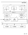
図1において、流量計測装置1の内部には、複数のガス器具A,B,C(例えば、ファンヒータ、ガステーブル、ストーブ、ガスオーブン)に対してガス供給を行うための計測流路2が配設されている。
(Embodiment 1)
In FIG. 1, a
この計測流路2には、主に異常時に計測流路自身を遮断するガス遮断弁3と、ユーザに対して視覚的な報知を行う表示部4と、計測流路に流れるガス流量を検出する流量計測手段5が配置されている。
The
また、流量計測手段4の出力を入力するとともに、ガス遮断弁3を制御するコントロール部6が設けられている。
Further, a
そして、コントロール部6は、CPU(中央処理装置)7、ROM(リード・オンリー・メモリ)8、RAM(ランダム・アクセス・メモリ)9、および入出力ポート10を備え、これらは互いにバス11によって接続されている。
The
入出力ポート10には、流量計測手段5と、ガス遮断弁3を駆動する駆動回路12と表示部4を駆動する駆動回路13が接続されている。
Connected to the input /
このコントロール部6では、CPU7がRAM9をワーキングエリアとして、ROM8に格納されてプログラムを実行することによって、流量計測装置1としての機能を実現するようになっている。
In the
ここで、流量計測手段5の動作について図2を用いて説明する。 Here, the operation of the flow rate measuring means 5 will be described with reference to FIG.
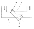
図2において、計測流路2は矩形断面を持っており、ガスの流れる方向と直角方向にある壁面には計測流路2を挟んで一対の超音波送受信器14、15が上流側と下流側で角度φを有して斜めに対向して装着されている。つまり、超音波送受信器14、15間を伝搬
する超音波が計測流路2を斜めに横切るように設定されている。
In FIG. 2, the
超音波送受信器4、5間で交互に超音波を送受信させて流体の流れに対して順方向と逆方向との超音波の伝搬時間差を一定間隔おいて測定し、伝搬時間差信号として出力する働きを持つ。
The function of transmitting ultrasonic waves alternately between the ultrasonic transmitters /
この伝搬時間差信号を受けて計算手段(図示せず)により被計測流体の流速及び流量を算出するものである。 In response to this propagation time difference signal, the calculation means (not shown) calculates the flow velocity and flow rate of the fluid to be measured.
算出式を下記に示す。 The calculation formula is shown below.
図2においてLは測定距離であり、t1を上流からの伝達時間、t2を下流からの伝達時間、Cを音速とすると、計測ポイントの時刻Tでの流速Vは
V=(L/2cosφ)((1/t1)−(1/t2)) (1)
である。
In FIG. 2, L is a measurement distance, where t1 is the transmission time from the upstream, t2 is the transmission time from the downstream, and C is the speed of sound, the flow velocity V at time T of the measurement point is V = (L / 2cosφ) ( (1 / t1)-(1 / t2)) (1)
It is.
更に、流速を計測するポイントによって計測流路2に流れるガスは突発的に変化するので、流路全体からみた流速よりも大きかったり、小さかったりする場合があり、その影響を小さくするために前回計測した流速V'との平均を計測流速としている。
Furthermore, since the gas flowing in the
なお、流量計測手段5に関しては、超音波方式の計測手段を使用しているが、他の流量計測方式、例えば、フルディック方式などの短時間に一定サイクルで連続計測可能であれば使用可能である。 As the flow rate measuring means 5, an ultrasonic type measuring means is used. However, other flow rate measuring methods such as a full dick method can be used as long as they can be continuously measured in a constant cycle in a short time. is there.
本実施の形態における計測の時間間隔は超音波の送受信が可能な範囲で設定できるが、例えば2秒間隔の計測を行っている。 Although the measurement time interval in the present embodiment can be set within a range where ultrasonic waves can be transmitted and received, for example, measurement is performed at intervals of 2 seconds.
更に、時間間隔を小さくすることは測定原理上可能であるが、測定時間間隔を小さくすることは器具判別を瞬時に行う点では有利となるが、電池の消耗が大きくなるなどの課題がある。 Furthermore, although it is possible to reduce the time interval in terms of the measurement principle, reducing the measurement time interval is advantageous in that the instrument discrimination is performed instantaneously, but there are problems such as an increase in battery consumption.
また、計測時間を従来のガスメータで使用している膜式方式と同等の計測間隔が2桁オーダーの秒数間隔になると、流量変化の差分値を見て動作しているガス器具を判別することが困難になり、コストや器具判別の性能面からバランスの良い時間として本実施の形態では2秒間隔で計測を行っている。 Also, if the measurement interval is the same as the membrane method used in the conventional gas meter, and the second interval is in the order of two digits, the operating gas appliance is identified by looking at the difference value of the flow rate change. In this embodiment, the measurement is performed at intervals of 2 seconds as a well-balanced time from the viewpoint of cost and instrument discrimination performance.
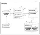
図3は、実施の形態1における流量計測装置1の機能を示すものである。この図で示すように、本実施の形態の流量計測装置1は、先ずガス流量を計測する流量計測手段5と、少なくとも起動判別を行うために予め登録しておく各種器具情報を記憶する器具情報記憶手段16と、流量計測手段5が計測する計測流量の履歴を記憶する計測流量履歴記憶手段17と、少なくともガス器具が使用された場合にそのガス器具を特定する器具判別手段18と、計測流量に流量変化が発生しているか監視するとともに、器具判別手段18が判別を行うために必要な各種情報を計測流量履歴情報から算出する流量演算手段19とを備えている。 FIG. 3 shows the function of the flow rate measuring apparatus 1 in the first embodiment. As shown in this figure, the flow rate measuring device 1 according to the present embodiment first includes a flow rate measuring means 5 for measuring a gas flow rate, and instrument information for storing various instrument information registered in advance for at least activation determination. Storage means 16, measurement flow history storage means 17 for storing a history of measurement flow rates measured by the flow measurement means 5, instrument discrimination means 18 for identifying the gas appliance when at least the gas appliance is used, and measurement flow rate And a flow rate calculation means 19 for calculating various information necessary for the instrument discrimination means 18 to make a discrimination from the measured flow rate history information.
流量計測手段5は、流量計測部とコントロール部6によって実現される。そして、流量計測手段5は、2秒毎に計測する計測流路2に流れるガス流量を計測流量履歴記憶手段17に記憶する。
The flow rate measuring means 5 is realized by the flow rate measuring unit and the
計測流量履歴記憶手段17は、RAM9によって実現され、器具判別手段18が動作し
ているガス器具を特定できるために計測したガス流量を履歴情報として数分間分記憶している。
The measured flow rate
なお、本実施の形態において計測流量履歴記憶手段17は、30秒前まで履歴情報として計測したガス流量を記憶している。 In the present embodiment, the measured flow rate history storage means 17 stores the gas flow rate measured as history information until 30 seconds ago.
器具情報記憶手段16は、RAM9によって実現され、図4に示すように器具を起動したときのガス流量、すなわち起動ガス流量と制御パターンとが器具毎に登録値として記憶する。
The appliance information storage means 16 is realized by the
なお、起動ガス流量(登録値)は、ガス器具の起動判別に用いる情報なので、器具起動情報記憶手段16aに記憶され、制御パターンはガス器具の制御判別に用いる情報なので、器具制御情報記憶手段16bに記憶されるものとする。
The starting gas flow rate (registered value) is information used for determining the activation of the gas appliance, and is stored in the appliance activation
この情報は、ガス事業者が事前に端末等を使用して登録するなどして器具情報記憶手段16に記憶させておくものとする。 This information is stored in the appliance information storage means 16 by a gas company registering in advance using a terminal or the like.
また、制御パターンの急・緩とは、本実施の形態においていえば、流量変化が発生している期間において8秒以上連続して制御によるガス流量変化が発生する(8秒以上連続して前回の計測ガス流量値と現計測ガス流量値の差(絶対値)が3[L/h]以上である)パターンは「緩」で、8秒未満でガス流量変化が終了するパターンは「急」とする。8秒は、変更可能とする。 In the present embodiment, the sudden / slow control pattern means that the gas flow rate change due to the control is continuously generated for 8 seconds or more in the period during which the flow rate change is occurring (the previous time continuously for 8 seconds or more). The difference (absolute value) between the measured gas flow rate value and the current measured gas flow rate value is 3 [L / h] or more) The pattern is “slow”, and the pattern in which the gas flow rate change ends in less than 8 seconds is “sudden” And 8 seconds can be changed.
そして、図10から図12のようにON/OFFを繰り返すことで温度調節を行う器具については、「ON/OFF」とする。 And about the instrument which temperature-controls by repeating ON / OFF like FIGS. 10-12, it is set as "ON / OFF."
ただし、対象としている期間における全ての第1の演算手段(後述)が算出する差分値が80[L/h]未満である場合に限定する。 However, it is limited to the case where the difference value calculated by all the first calculation means (described later) in the target period is less than 80 [L / h].
この80[L/h]という境界値は、可変で50[L/h]、60[L/h]、70[L/h]、100[L/h]などユーザ毎に保有しているガス器具の組み合わせによって設定可能であるものとする。 The boundary value of 80 [L / h] is variable, such as 50 [L / h], 60 [L / h], 70 [L / h], and 100 [L / h]. It can be set by the combination of appliances.
流量演算手段19は、第1の演算手段19aと第2の演算手段19bとで構成され、両者は、コントロール部6によって実現される。
The flow rate calculation means 19 includes a first calculation means 19 a and a second calculation means 19 b, both of which are realized by the
第1の演算手段19aとは、計測流量履歴記憶手段17を参照して、現在の流量値と2回(4秒)前の計測流量値との差分を計算する演算手段である。 The first calculation means 19a is a calculation means that refers to the measured flow rate history storage means 17 and calculates a difference between the current flow rate value and the measured flow rate value two times before (4 seconds).
第2の演算手段19bとは、計測流量履歴記憶手段17を参照して第1の演算手段19aが計算する差分値が予め定めた正の閾値より大きくなった時刻aより4秒前の計測流量Qaと、時刻a後、第1の演算手段19aが計算する差分値の絶対値が前記した正の閾値より小さくなった時刻bの計測流量Qbとの流量差(Qb−Qa)を起動流量の実測値として計算する処理部である。
The second calculation means 19b refers to the measured
器具判別手段18は、第1の演算手段19aが算出する差分値の絶対値が予め定めた閾値(例えば、3[L/h])以上になった場合に流量変化が発生したと判別し、同差分値の絶対値が3[L/h]未満になると流量変化が収束したと判別し、この流量変化を発生させたガス器具を特定するものである。 The appliance discriminating means 18 discriminates that the flow rate change has occurred when the absolute value of the difference value calculated by the first calculating means 19a is equal to or greater than a predetermined threshold (for example, 3 [L / h]), When the absolute value of the difference value is less than 3 [L / h], it is determined that the flow rate change has converged, and the gas appliance that has caused this flow rate change is specified.
そして、起動判別手段18aと制御判別手段(図示せず)と停止判別手段(図示せず)とで構成される。これら手段は、コントロール部6によって実現される。
And it is comprised by the starting determination means 18a, the control determination means (not shown), and the stop determination means (not shown). These means are realized by the
起動判別手段18aは、第2の演算手段19bが計算する起動流量の実測値との流量差を器具起動情報記憶手段16aに登録される起動流量の登録値と比較して、例えば、両者が±5[L/h]の誤差であるもの(複数ある場合は、最も近いもの)を対象としている流量変化がガス器具の起動によるものだと判別する。 The activation determination means 18a compares the flow rate difference with the actual measurement value of the activation flow rate calculated by the second calculation means 19b with the registered value of the activation flow rate registered in the appliance activation information storage means 16a. It is determined that the flow rate change targeted for the error of 5 [L / h] (or the closest one if there are multiple) is due to the activation of the gas appliance.
なお、誤差を考慮する理由は、外気温や使用されるガス器具の台数などに計測流路2でのガス圧が若干変化するためである。
The reason for considering the error is that the gas pressure in the
次に図5にファンヒータを動作させた時の流量計測手段5が計測するガス流量の時間特性を示す。 Next, FIG. 5 shows the time characteristic of the gas flow rate measured by the flow rate measuring means 5 when the fan heater is operated.
図5から分かるように起動直後はホットダッシュ機能によってある一定のガス流量が流れ(起動ガス流量が一定である期間があって)、その後外気温と動作設定によってガス流量(時間特性)が変化する130[L/h]くらいから40[L/h]辺りまである程度長いの時間(70秒目から116秒目までの間)をかけながらガス流量が変化している。 As can be seen from FIG. 5, immediately after startup, a certain gas flow rate flows by the hot dash function (there is a period during which the startup gas flow rate is constant), and then the gas flow rate (time characteristic) changes depending on the outside air temperature and operation settings. The gas flow rate changes while taking a certain amount of time (between the 70th and 116th seconds) from about 130 [L / h] to around 40 [L / h].
なお、この流量変化発生するタイミングは外気温・動作設定によって変わるので、流量変化が発生するタイミングを予め推測できるものではない。 In addition, since the timing at which this flow rate change occurs depends on the outside air temperature / operation setting, the timing at which the flow rate change occurs cannot be estimated in advance.
更に、図6にガステーブルを動作させた時の流量計測手段5が計測するガス流量の時間特性である。 Further, FIG. 6 shows the time characteristics of the gas flow rate measured by the flow rate measuring means 5 when the gas table is operated.
この時ガステーブルを着火後、火力調節レバーを「強」→「中」→「弱」→「中」→「強」→「弱」→「強」と変化させている。 At this time, after the gas table is ignited, the heating power adjustment lever is changed from “strong” → “medium” → “weak” → “medium” → “strong” → “weak” → “strong”.
図6から分かるように火力調節レバーによってユーザはいかようにもユーザがガス流量を変化させることができるとともに、その制御のタイミングも変えることができる。 As can be seen from FIG. 6, the user can change the gas flow rate by the heating power adjustment lever, and the timing of the control can be changed.
そして、ファンヒータの場合と異なり、ユーザが火力調節レバーを操作することによってガス流量変化が発生するので比較的短時間にガス流量が変化していることがわかる。 And unlike the case of a fan heater, since a gas flow rate change generate | occur | produces when a user operates a thermal-power adjustment lever, it turns out that the gas flow rate is changing in a comparatively short time.
なお、プッシュ式のガステーブルの多くは、着火直後に立ち消えにくくするために、ユーザが着火するために着火用のボタンを押下すると火力調節レバーが何処にあってもある程度大きいガスが流れるように火力調節レバーが自動で火力が最大の方向に動く機構になっている。 Many push-type gas tables are designed to make it difficult for them to go out immediately after ignition. The adjustment lever is a mechanism that automatically moves the heating power in the maximum direction.
だから、ガステーブルの着火直後は最大ガス消費量に近い起動流量になっている。 Therefore, immediately after the ignition of the gas table, the starting flow rate is close to the maximum gas consumption.
そして、本実施の形態における流量計測装置の動作について説明する。ここでは、図7のフローチャートを用いて説明する。 And operation | movement of the flow volume measuring apparatus in this Embodiment is demonstrated. Here, it demonstrates using the flowchart of FIG.
本実施の形態では、図11に示すガスオーブンを100℃設定で動作させるものとする。時刻0[s]の時点から始まるものとする。 In the present embodiment, it is assumed that the gas oven shown in FIG. It starts from the time 0 [s].
なお、後述する特定のガス器具とは本実施の形態においてはガスオーブンのことをいう。また、特定のガス器具は、ガスオーブンに限定するものでなく、床暖房であってもよく、ON/OFFを繰り返しながら設定温度に対象物(庫内やパネル)を温めるガス器具を
指し示すものとする。
In addition, the specific gas appliance mentioned later means a gas oven in this Embodiment. In addition, the specific gas appliance is not limited to the gas oven, but may be floor heating, and indicates a gas appliance that warms an object (inside the cabinet or panel) to a set temperature while repeating ON / OFF. To do.
先ず、流量計測手段5が計測流路2に流れるガス流量を2秒おきに計測する(S701)。また、ガスオーブンが起動するまでは、流量変化は発生していないので、流量変化が発生するまで何もしないで次の計測する時間まで待機する。
First, the flow rate measuring means 5 measures the gas flow rate flowing through the
そして、ガスオーブンが動作を始めて第1の演算手段19aが計算する4秒前の計測流量との差分値が3[L/h]以上になることで流量変化を検知すると(S702)、ガス流量が安定するまで待機する(S708)。 Then, when a change in the flow rate is detected when the difference value from the measured flow rate before 4 seconds calculated by the first calculation means 19a after the gas oven starts operating is 3 [L / h] or more (S702), the gas flow rate is detected. Waits until it becomes stable (S708).
ガス流量が安定するとは、時間帯Aでは2秒前の計測流量との差分値が3[L/h]未満になると安定したと見なし、時間帯A以外の時間帯(時間帯B)では、4秒前の計測流量との差分値が3[L/h]未満になると安定したと見なす。
The gas flow rate is stable when time zone A is considered to be stable when the difference from the measured
時間帯Aとは、特定のガス器具であるガスオーブンをユーザが動作させて初めてON状態(ガスが流れる状態)になった時のON状態継続時間(動作時間)により時間帯Aの長さが決まる。 The time zone A is the length of the time zone A according to the ON state duration (operation time) when the gas oven, which is a specific gas appliance, is turned on (the gas flows) for the first time after the user operates the gas oven. Determined.
図8に動作時間と時間帯Aの長さとの対応を示すテーブルを示す。このテーブルのことを本実施の形態では、時間帯決定テーブルと呼ぶ。 FIG. 8 shows a table showing the correspondence between the operation time and the length of the time zone A. In the present embodiment, this table is referred to as a time zone determination table.
そして、時間帯Aの起点は、ガスオーブンがOFF状態になった点から始まる。 The starting point of the time zone A starts from the point where the gas oven is turned off.
ガスオーブンは、図11に示すようにユーザがガスオーブンを動作させると自身の制御によってON/OFFする。そのため、時間帯Aの起点はOFFになった各々の時点である。 As shown in FIG. 11, the gas oven is turned on / off by its own control when the user operates the gas oven. Therefore, the starting point of the time zone A is each time point when it is turned OFF.
ただし、時間帯Aの長さは、ユーザが動作させて初めてON状態(ガスが流れる状態)になった時のON状態継続時間によってのみ決定される。 However, the length of the time zone A is determined only by the ON state duration when the user enters the ON state (the state in which gas flows) for the first time.
つまり、ユーザがガスオーブンを手動でOFFするか調理が終了するなど行うことによって、定義された時間帯A内にガスオーブンの起動流量を検出しなかった時点で初期化される。 That is, it is initialized when the user does not detect the starting flow rate of the gas oven within the defined time zone A, for example, when the user manually turns off the gas oven or finishes cooking.
なお初期化とは、時間帯Aが無い状態(全てが時間帯B)であることをさし、ガスオーブンの動作がないと流量計測装置1が認識するということである。 The initialization means that there is no time zone A (all time zone B), and that the flow measuring device 1 recognizes that there is no operation of the gas oven.
流量変化を検知すると(S702)、特定のガス器具(ガスオーブン)の初めてON状態になった時のON状態継続時間(動作時間)を参照し(S703)、そして、時間帯決定テーブルを参照する(S704)。 When the flow rate change is detected (S702), the ON state duration (operation time) when the specific gas appliance (gas oven) is turned ON for the first time is referred to (S703), and the time zone determination table is referred to. (S704).
今の場合では、ガスオーブンは動作していなかったので時間帯は時間帯Bに決定する。そして時間帯が時間帯Bであるので(S705)、安定条件を4秒安定と決定する(S707)。 In the present case, the time zone is determined to be time zone B because the gas oven was not operating. Since the time zone is the time zone B (S705), the stable condition is determined to be stable for 4 seconds (S707).
計測流量に流量変化が発生してからステップS707で決めた安定条件が成立するまでは次の流量計測まで何もしないで(S708)、安定条件が成立すると第2の演算手段103bが計算する(S709)。
Until the stable condition determined in step S707 is satisfied after the flow rate change occurs in the measured flow rate, nothing is performed until the next flow rate measurement (S708), and when the stable condition is satisfied, the
それから、起動判別手段18aは、起動流量の実測値と器具起動情報記憶手段16aに
予め登録されている起動流量と比較して、起動した可能性があるガス器具を判別する(S710)。
Then, the
本実施の形態では、起動流量の実測値は、230[L/h]付近であるので、ガスオーブンが起動したと判別する。 In the present embodiment, since the actual measured value of the activation flow rate is around 230 [L / h], it is determined that the gas oven has been activated.
そして、時間帯Bでガスオーブンが起動したと判別したので、ON状態が継続した時間を流量計測装置は記憶しておく。なおこの時間は、本実施の形態では2分とする。 Then, since it is determined that the gas oven is activated in the time zone B, the flow rate measuring device stores the time during which the ON state is continued. This time is 2 minutes in this embodiment.
その後、ガスオーブンがON状態になる流量変化が生じた場合には(S702)、特定のガス器具であるガスオーブンの動作時間(2分)を参照して、時間帯決定テーブルを参照し(S704)、時間帯Aの長さ(1分)を決定する。 Thereafter, when a flow rate change that turns on the gas oven occurs (S702), the operation time (2 minutes) of the gas oven that is the specific gas appliance is referred to, and the time zone determination table is referenced (S704). ) And determine the length of time zone A (1 minute).
本実施の形態では、対象としている流量変化は、前回のガスオーブンの停止時点から約30秒後に発生しているので、流量変化が発生した時点は時間帯Aにあると見なすことができる(S705)。そうすると、安定条件を2秒安定と決定する(S706)。 In the present embodiment, since the target flow rate change occurs about 30 seconds after the previous stop time of the gas oven, it can be considered that the time point when the flow rate change occurs is in the time zone A (S705). ). Then, the stable condition is determined to be stable for 2 seconds (S706).
計測流量に流量変化が発生してからステップS706で決めた安定条件が成立するまでは次の流量計測まで何もしないで(S708)、安定条件が成立すると第2の演算手段19bが計算する(S709)。 Until the stable condition determined in step S706 is satisfied after the flow rate change occurs in the measured flow rate, nothing is performed until the next flow rate measurement (S708), and when the stable condition is satisfied, the second calculation means 19b calculates ( S709).
それから、起動判別手段18aは、起動流量の実測値と器具起動情報記憶手段16aに予め登録されている起動流量と比較して、起動した可能性があるガス器具を判別する(S710)。
Then, the
なお、本実施の形態においては、安定条件を時間帯Aでは2秒前の計測流量と現在の計測流量との差分値の絶対値が3[L/h]未満になることとし、時間帯Bでは4秒前の計測流量と現在の計測流量との差分値の絶対値が3[L/h]未満になることとした。
In the present embodiment, in the time zone A, the absolute value of the difference value between the measured flow rate two seconds before and the current measured flow rate is less than 3 [L / h] in the time zone A, and the time zone B Then, the absolute value of the difference value between the measured
但し、ガス流量が安定している時間の長さを変えてもよい。また、時間帯Aでは4秒前の計測流量と現在の計測流量との差分値の絶対値が6[L/h]未満になることとし、時間帯Bでは4秒前の計測流量と現在の計測流量との差分値の絶対値が3[L/h]未満になることとするように差分値の大きさを変更するようにしても構わない。
However, the length of time during which the gas flow rate is stable may be changed. In time zone A, the absolute value of the difference between the measured
そして、更に図10のガスオーブンの35℃設定に対応するために、次のように第2の演算手段19bがある条件が成立するときにのみ以下のように起動流量を再計算するようにしてもよい。 Further, in order to correspond to the 35 ° C. setting of the gas oven of FIG. 10, the starting flow rate is recalculated as follows only when a certain condition is satisfied as described below. Also good.
ある条件とは、時間帯Aで流量変化が発生して、且つ、決定された安定条件で算出した起動流量がほぼ0[L/h]である場合のことである。 A certain condition is a case where a flow rate change occurs in the time zone A and the starting flow rate calculated under the determined stable condition is approximately 0 [L / h].
その場合において、発生した流量変化の過程において最も大きいガス流量値と流量変化発生直前のガス流量の流量差を起動流量として再計算する。 In that case, the flow rate difference between the largest gas flow rate value and the gas flow rate immediately before the flow rate change in the process of the generated flow rate change is recalculated as the starting flow rate.
これによって、安定する流量が無い程短い間にON/OFFする場合にも対応することができる。 As a result, it is possible to cope with the case where the flow rate is turned on and off in a short time without a stable flow rate.
なお、起動時のガス流量変化にオーバシュートをともなうガス器具があるので、この方法は、短時間でON/OFFするガス器具以外には効果的ではない。 In addition, since there is a gas appliance with an overshoot in the gas flow rate change at startup, this method is not effective except for a gas appliance that is turned on / off in a short time.
以上のように、本実施の形態においては、ガス器具が起動したときに消費する起動ガス流量によって動作したガス器具を判別することによって、膨大な流量パターンを必要としなくても自身の下流に接続され、且つ、ユーザによって使用された(起動した)ガス器具を判別できる。 As described above, in the present embodiment, by determining the gas appliance that has been operated based on the startup gas flow rate that is consumed when the gas appliance is started up, it is connected downstream of itself without requiring a huge flow pattern. And the gas appliance used (activated) by the user can be determined.
また、短時間でON/OFFを繰り返すことによって制御対象物の温度をコントロールするガス器具は、動作設定によって流量パターンも様々で、且つ、流量が安定している時間が短い。そのため、ON時間が短かったりするガス器具が動作する可能性がある時間帯の起動流量の求める方法を他の時間帯と異なる方法にすることで、オーバシュートがあるガス器具の特性を考慮し、更に、ON時間の短いガス器具の特性にも対応して起動ガス流量を算出することができる。 Further, the gas appliance that controls the temperature of the object to be controlled by repeating ON / OFF in a short time has various flow patterns depending on the operation setting, and the time during which the flow rate is stable is short. Therefore, considering the characteristics of gas appliances with overshoot by making the method for determining the starting flow rate in the time zone in which the gas appliance with a short ON time or the possibility of operation differ from other time zones, Furthermore, the starting gas flow rate can be calculated corresponding to the characteristics of the gas appliance having a short ON time.
これによって、動作しているガス器具を誤判別する確率を低くすることができる。 As a result, it is possible to reduce the probability of misidentifying the operating gas appliance.
以上で説明した手段は、CPU(またはマイコン)、RAM、ROM、記憶・記録装置、I/Oなどを備えた電気・情報機器、コンピュータ、サーバ等のハードリソースを協働させるプログラムの形態で実施してもよい。 The means described above are implemented in the form of a program for cooperating hardware resources such as a CPU (or microcomputer), RAM, ROM, storage / recording device, electrical / information device including I / O, computer, server, etc. May be.
プログラムの形態であれば、磁気メディアや光メディアなどの記録媒体に記録したりインターネットなどの通信回線を用いて配信したりすることで新しい機能の配布・更新やそのインストール作業が簡単にできる。 In the form of a program, new functions can be distributed / updated and installed easily by recording them on a recording medium such as magnetic media or optical media or distributing them using a communication line such as the Internet.
以上のように、本発明にかかる流量計測装置及びそのプログラムは、ガスメータの下流に接続されたガス器具が各時刻におけるガス使用量(流量)の計算を精度よく行うことができる。そのため、ガス器具と特定できない場合にはガス漏れ等の可能性を疑うことができ、結果的にはガス器具が適正に使用されているか監視することにつながる。つまりはガス使用者に対しての保安サービス等の用途にも適用できる。 As described above, the flow rate measuring device and the program thereof according to the present invention can accurately calculate the amount of gas used (flow rate) at each time by the gas appliance connected downstream of the gas meter. Therefore, when it cannot be identified as a gas appliance, the possibility of gas leakage or the like can be suspected, and as a result, it is monitored whether the gas appliance is used properly. In other words, it can also be applied to uses such as security services for gas users.
1 流量計測装置
5 流量計測手段
18 器具判別手段
18a 起動判別手段
16 器具情報記憶手段
16a 器具起動情報記憶手段
19 流量演算手段
19a 第1の演算手段
19b 第2の演算手段
DESCRIPTION OF SYMBOLS 1
Claims (6)
前記流量計測手段が計測するガス流量をもとに起動ガス流量の実測値を計算する流量演算手段と、
ガス器具起動時の起動ガス流量の登録値を予め記憶する器具起動情報記憶手段と、
前記流量演算手段で計算された実測値と前記器具起動情報記憶手段に記憶された登録値とを比較して実際に起動したガス器具を判別する器具判別手段と、で構成される流量計測装置において、
前記器具判別手段がON状態とOFF状態を繰り返す特定のガス器具の動作を判別した後、そのガス器具の使用流量が停止した場合に、その停止した時刻から前記特定のガス器具のON状態の時間に応じて定めた所定時間において前記流量演算手段は前記起動ガス流量の実測値の計算方法を変更することを特徴とする流量計測装置。 A flow rate measuring means for measuring the gas flow rate at a constant time interval T;
And flow rate calculating means and said flow rate measuring means for calculating a measured value of the initiation gas flow rate in the preparative even gas flow to be measured,
Appliance activation information storage means for storing in advance a registered value of the activation gas flow rate at the time of activation of the gas appliance;
In a flow rate measuring device comprising: an instrument discriminating unit that discriminates an actually activated gas appliance by comparing an actual measurement value calculated by the flow rate computing unit and a registered value stored in the appliance activation information storage unit ,
After said appliance determination unit has determined an operation of a specific gas appliance repeating ON and OFF states, when the use flow rate of the gas appliance is stopped, the time from the stopped time of the ON state of the specific gas appliance The flow rate calculation means changes the calculation method of the measured value of the starting gas flow rate for a predetermined time determined according to the above.
前記流量計測手段がガス流量を計測する度に、差分時間N前の流量との差分値を演算するようにした第1の演算手段と、
前記第1の演算手段が演算した差分値が予め定めた正の閾値より大きくなった時刻aより差分時間N前における流量Qaと、その時刻aの後において前記第1の演算手段が演算した差分値の絶対値が前記正の閾値より小さくなった時刻bにおける流量Qbとを求め、それらの流量差(Qb−Qa)を前記起動ガス流量の実測値として計算する第2の演算手段と、で構成され、
前記流量演算手段は、前記特定のガス器具が停止した時刻からの所定時間において、前記差分時間Nを変更することで計算方法を変更する請求項1に記載の流量計測装置。 The flow rate calculation means is
A first calculation unit configured to calculate a difference value from the flow rate before the difference time N every time the flow rate measurement unit measures the gas flow rate;
The flow rate Qa before the difference time N from the time a when the difference value calculated by the first calculation means is greater than a predetermined positive threshold, and the difference calculated by the first calculation means after the time a A second computing means for obtaining a flow rate Qb at time b when the absolute value of the value becomes smaller than the positive threshold value and calculating a flow rate difference (Qb−Qa) as an actual measurement value of the starting gas flow rate; Configured,
The flow rate measurement device according to claim 1 , wherein the flow rate calculation unit changes the calculation method by changing the difference time N in a predetermined time from the time when the specific gas appliance is stopped.
前記流量計測手段がガス流量を計測する度に、差分時間N前の流量との差分値を演算するようにした第1の演算手段と、
前記第1の演算手段が演算した差分値が予め定めた正の閾値より大きくなった時刻aより差分時間N前における流量Qaと、その時刻aの後において前記第1の演算手段が演算した差分値の絶対値が前記正の閾値より小さくなった時刻bにおける流量Qbとを求め、そ
れらの流量差(Qb−Qa)を前記起動ガス流量の実測値として計算する第2の演算手段と、で構成され、
前記特定のガス器具が停止した時刻からの所定時間において、前記正の閾値の大きさが異なる請求項1に記載の流量計測装置。 The flow rate calculation means is
A first calculation unit configured to calculate a difference value from the flow rate before the difference time N every time the flow rate measurement unit measures the gas flow rate;
The flow rate Qa before the difference time N from the time a when the difference value calculated by the first calculation means is greater than a predetermined positive threshold, and the difference calculated by the first calculation means after the time a The flow rate Qb at time b when the absolute value of the value becomes smaller than the positive threshold is obtained.
And a second calculation means for calculating these flow rate differences (Qb-Qa) as the actual measured values of the starting gas flow rate,
Wherein the predetermined time from the time that a particular gas appliance has stopped, the flow rate measuring device according to claim 1, the magnitude of said positive threshold is different.
The program which makes a computer perform at least one part of the flow measuring device of any one of Claim 1 to 5 .
Priority Applications (1)
| Application Number | Priority Date | Filing Date | Title |
|---|---|---|---|
| JP2007301483A JP5163072B2 (en) | 2007-11-21 | 2007-11-21 | Flow measuring device and program thereof |
Applications Claiming Priority (1)
| Application Number | Priority Date | Filing Date | Title |
|---|---|---|---|
| JP2007301483A JP5163072B2 (en) | 2007-11-21 | 2007-11-21 | Flow measuring device and program thereof |
Publications (3)
| Publication Number | Publication Date |
|---|---|
| JP2009128104A JP2009128104A (en) | 2009-06-11 |
| JP2009128104A5 JP2009128104A5 (en) | 2011-01-13 |
| JP5163072B2 true JP5163072B2 (en) | 2013-03-13 |
Family
ID=40819200
Family Applications (1)
| Application Number | Title | Priority Date | Filing Date |
|---|---|---|---|
| JP2007301483A Active JP5163072B2 (en) | 2007-11-21 | 2007-11-21 | Flow measuring device and program thereof |
Country Status (1)
| Country | Link |
|---|---|
| JP (1) | JP5163072B2 (en) |
Cited By (1)
| Publication number | Priority date | Publication date | Assignee | Title |
|---|---|---|---|---|
| CN111174841A (en) * | 2019-12-30 | 2020-05-19 | 金卡智能集团股份有限公司 | Oscillatory flow filtering method for electronic meter at zero flow point |
Families Citing this family (1)
| Publication number | Priority date | Publication date | Assignee | Title |
|---|---|---|---|---|
| JP5285980B2 (en) * | 2008-07-03 | 2013-09-11 | 矢崎エナジーシステム株式会社 | Gas appliance discrimination device and gas appliance discrimination method |
Family Cites Families (5)
| Publication number | Priority date | Publication date | Assignee | Title |
|---|---|---|---|---|
| JPH0567284A (en) * | 1991-09-09 | 1993-03-19 | Matsushita Electric Ind Co Ltd | Device for estimating flow rate change |
| JP3967689B2 (en) * | 2003-03-14 | 2007-08-29 | 三菱電機株式会社 | Cooking device and heating control method. |
| JP4729971B2 (en) * | 2005-05-09 | 2011-07-20 | パナソニック株式会社 | Gas meter device |
| JP4581882B2 (en) * | 2005-07-21 | 2010-11-17 | パナソニック株式会社 | Flow measuring device |
| JP4581881B2 (en) * | 2005-07-21 | 2010-11-17 | パナソニック株式会社 | Gas meter device |
-
2007
- 2007-11-21 JP JP2007301483A patent/JP5163072B2/en active Active
Cited By (2)
| Publication number | Priority date | Publication date | Assignee | Title |
|---|---|---|---|---|
| CN111174841A (en) * | 2019-12-30 | 2020-05-19 | 金卡智能集团股份有限公司 | Oscillatory flow filtering method for electronic meter at zero flow point |
| CN111174841B (en) * | 2019-12-30 | 2021-10-19 | 金卡智能集团股份有限公司 | Oscillatory flow filtering method for electronic meter at zero flow point |
Also Published As
| Publication number | Publication date |
|---|---|
| JP2009128104A (en) | 2009-06-11 |
Similar Documents
| Publication | Publication Date | Title |
|---|---|---|
| JP5288587B2 (en) | Flow measuring device | |
| WO2008050490A1 (en) | Flowmeter and its program | |
| JP2008180707A (en) | Flow rate measuring apparatus and gas supplying system | |
| JP2007024750A (en) | Flow measuring instrument | |
| JP5092723B2 (en) | Flow measuring device | |
| WO2017110034A1 (en) | Flow rate measurement device | |
| JP5163072B2 (en) | Flow measuring device and program thereof | |
| JP4591248B2 (en) | Gas utilization system | |
| JP6131217B2 (en) | Piping capacity estimation device, gas leak inspection device, piping capacity estimation method, and piping capacity estimation program | |
| JP2004077248A (en) | Flow rate measuring device with low power consumption and high sampling rate, and gas meter applying the same | |
| JP5076506B2 (en) | Flow measuring device and program thereof | |
| US20130110413A1 (en) | Estimating gas usage in a gas burning device | |
| JP5167825B2 (en) | Flow measuring device | |
| JP5239239B2 (en) | Flow measuring device and program thereof | |
| JP5169370B2 (en) | Flow measuring device and program thereof | |
| JP5293523B2 (en) | Flow measuring device | |
| JP5162953B2 (en) | Flow measuring device and program thereof | |
| JP5272874B2 (en) | Flow measuring device | |
| JP2010085383A (en) | Flow measuring device | |
| JP2009036648A (en) | Flow rate measuring device and its program | |
| JP4930000B2 (en) | Flow measuring device | |
| JP5169049B2 (en) | Flow measuring device | |
| WO2013157257A1 (en) | Flow rate measurement device | |
| KR101238391B1 (en) | Combustion control method for preventing resonance noise range | |
| JP4920447B2 (en) | Gas appliance discrimination device and discrimination method |
Legal Events
| Date | Code | Title | Description |
|---|---|---|---|
| A521 | Written amendment |
Free format text: JAPANESE INTERMEDIATE CODE: A523 Effective date: 20101122 |
|
| A621 | Written request for application examination |
Free format text: JAPANESE INTERMEDIATE CODE: A621 Effective date: 20101122 |
|
| RD01 | Notification of change of attorney |
Free format text: JAPANESE INTERMEDIATE CODE: A7421 Effective date: 20101214 |
|
| A131 | Notification of reasons for refusal |
Free format text: JAPANESE INTERMEDIATE CODE: A131 Effective date: 20120410 |
|
| A977 | Report on retrieval |
Free format text: JAPANESE INTERMEDIATE CODE: A971007 Effective date: 20120411 |
|
| A521 | Written amendment |
Free format text: JAPANESE INTERMEDIATE CODE: A523 Effective date: 20120606 |
|
| TRDD | Decision of grant or rejection written | ||
| A01 | Written decision to grant a patent or to grant a registration (utility model) |
Free format text: JAPANESE INTERMEDIATE CODE: A01 Effective date: 20121120 |
|
| A61 | First payment of annual fees (during grant procedure) |
Free format text: JAPANESE INTERMEDIATE CODE: A61 Effective date: 20121203 |
|
| FPAY | Renewal fee payment (event date is renewal date of database) |
Free format text: PAYMENT UNTIL: 20151228 Year of fee payment: 3 |
|
| R151 | Written notification of patent or utility model registration |
Ref document number: 5163072 Country of ref document: JP Free format text: JAPANESE INTERMEDIATE CODE: R151 |
|
| FPAY | Renewal fee payment (event date is renewal date of database) |
Free format text: PAYMENT UNTIL: 20151228 Year of fee payment: 3 |