JP5163065B2 - Non-aqueous electrolyte secondary battery and non-aqueous electrolyte composition - Google Patents
Non-aqueous electrolyte secondary battery and non-aqueous electrolyte composition Download PDFInfo
- Publication number
- JP5163065B2 JP5163065B2 JP2007295665A JP2007295665A JP5163065B2 JP 5163065 B2 JP5163065 B2 JP 5163065B2 JP 2007295665 A JP2007295665 A JP 2007295665A JP 2007295665 A JP2007295665 A JP 2007295665A JP 5163065 B2 JP5163065 B2 JP 5163065B2
- Authority
- JP
- Japan
- Prior art keywords
- carbonate
- secondary battery
- negative electrode
- aqueous electrolyte
- carbon
- Prior art date
- Legal status (The legal status is an assumption and is not a legal conclusion. Google has not performed a legal analysis and makes no representation as to the accuracy of the status listed.)
- Expired - Fee Related
Links
- 239000000203 mixture Substances 0.000 title claims description 31
- 239000011255 nonaqueous electrolyte Substances 0.000 title claims description 31
- 239000008151 electrolyte solution Substances 0.000 claims description 48
- 150000002825 nitriles Chemical class 0.000 claims description 45
- 239000003792 electrolyte Substances 0.000 claims description 35
- 150000001875 compounds Chemical class 0.000 claims description 27
- -1 carbonate ester Chemical class 0.000 claims description 24
- 229920000642 polymer Polymers 0.000 claims description 20
- OKTJSMMVPCPJKN-UHFFFAOYSA-N Carbon Chemical compound [C] OKTJSMMVPCPJKN-UHFFFAOYSA-N 0.000 claims description 18
- VAYTZRYEBVHVLE-UHFFFAOYSA-N 1,3-dioxol-2-one Chemical group O=C1OC=CO1 VAYTZRYEBVHVLE-UHFFFAOYSA-N 0.000 claims description 14
- SBLRHMKNNHXPHG-UHFFFAOYSA-N 4-fluoro-1,3-dioxolan-2-one Chemical group FC1COC(=O)O1 SBLRHMKNNHXPHG-UHFFFAOYSA-N 0.000 claims description 14
- 229910052799 carbon Inorganic materials 0.000 claims description 12
- 239000002033 PVDF binder Substances 0.000 claims description 11
- 229920002981 polyvinylidene fluoride Polymers 0.000 claims description 11
- 150000004649 carbonic acid derivatives Chemical class 0.000 claims description 10
- 239000011203 carbon fibre reinforced carbon Substances 0.000 claims description 9
- CREMABGTGYGIQB-UHFFFAOYSA-N carbon carbon Chemical compound C.C CREMABGTGYGIQB-UHFFFAOYSA-N 0.000 claims description 8
- 229910052736 halogen Inorganic materials 0.000 claims description 5
- 150000002367 halogens Chemical group 0.000 claims description 5
- OYUNTGBISCIYPW-UHFFFAOYSA-N 2-chloroprop-2-enenitrile Chemical compound ClC(=C)C#N OYUNTGBISCIYPW-UHFFFAOYSA-N 0.000 claims description 4
- 239000005001 laminate film Substances 0.000 claims description 4
- BVKZGUZCCUSVTD-UHFFFAOYSA-L Carbonate Chemical compound [O-]C([O-])=O BVKZGUZCCUSVTD-UHFFFAOYSA-L 0.000 claims 3
- 229910052744 lithium Inorganic materials 0.000 description 24
- 230000000052 comparative effect Effects 0.000 description 23
- 239000002904 solvent Substances 0.000 description 23
- 239000007773 negative electrode material Substances 0.000 description 21
- KYPOHTVBFVELTG-OWOJBTEDSA-N (e)-but-2-enedinitrile Chemical compound N#C\C=C\C#N KYPOHTVBFVELTG-OWOJBTEDSA-N 0.000 description 20
- WHXSMMKQMYFTQS-UHFFFAOYSA-N Lithium Chemical compound [Li] WHXSMMKQMYFTQS-UHFFFAOYSA-N 0.000 description 19
- OIFBSDVPJOWBCH-UHFFFAOYSA-N Diethyl carbonate Chemical compound CCOC(=O)OCC OIFBSDVPJOWBCH-UHFFFAOYSA-N 0.000 description 15
- 239000007774 positive electrode material Substances 0.000 description 15
- NLHHRLWOUZZQLW-UHFFFAOYSA-N Acrylonitrile Chemical compound C=CC#N NLHHRLWOUZZQLW-UHFFFAOYSA-N 0.000 description 13
- VZSRBBMJRBPUNF-UHFFFAOYSA-N 2-(2,3-dihydro-1H-inden-2-ylamino)-N-[3-oxo-3-(2,4,6,7-tetrahydrotriazolo[4,5-c]pyridin-5-yl)propyl]pyrimidine-5-carboxamide Chemical compound C1C(CC2=CC=CC=C12)NC1=NC=C(C=N1)C(=O)NCCC(N1CC2=C(CC1)NN=N2)=O VZSRBBMJRBPUNF-UHFFFAOYSA-N 0.000 description 12
- YLZOPXRUQYQQID-UHFFFAOYSA-N 3-(2,4,6,7-tetrahydrotriazolo[4,5-c]pyridin-5-yl)-1-[4-[2-[[3-(trifluoromethoxy)phenyl]methylamino]pyrimidin-5-yl]piperazin-1-yl]propan-1-one Chemical compound N1N=NC=2CN(CCC=21)CCC(=O)N1CCN(CC1)C=1C=NC(=NC=1)NCC1=CC(=CC=C1)OC(F)(F)F YLZOPXRUQYQQID-UHFFFAOYSA-N 0.000 description 10
- AFCARXCZXQIEQB-UHFFFAOYSA-N N-[3-oxo-3-(2,4,6,7-tetrahydrotriazolo[4,5-c]pyridin-5-yl)propyl]-2-[[3-(trifluoromethoxy)phenyl]methylamino]pyrimidine-5-carboxamide Chemical compound O=C(CCNC(=O)C=1C=NC(=NC=1)NCC1=CC(=CC=C1)OC(F)(F)F)N1CC2=C(CC1)NN=N2 AFCARXCZXQIEQB-UHFFFAOYSA-N 0.000 description 10
- 229910052782 aluminium Inorganic materials 0.000 description 9
- XAGFODPZIPBFFR-UHFFFAOYSA-N aluminium Chemical compound [Al] XAGFODPZIPBFFR-UHFFFAOYSA-N 0.000 description 9
- 230000014759 maintenance of location Effects 0.000 description 9
- HBBGRARXTFLTSG-UHFFFAOYSA-N Lithium ion Chemical compound [Li+] HBBGRARXTFLTSG-UHFFFAOYSA-N 0.000 description 7
- PXHVJJICTQNCMI-UHFFFAOYSA-N Nickel Chemical compound [Ni] PXHVJJICTQNCMI-UHFFFAOYSA-N 0.000 description 7
- 229910001416 lithium ion Inorganic materials 0.000 description 7
- HZNVUJQVZSTENZ-UHFFFAOYSA-N 2,3-dichloro-5,6-dicyano-1,4-benzoquinone Chemical compound ClC1=C(Cl)C(=O)C(C#N)=C(C#N)C1=O HZNVUJQVZSTENZ-UHFFFAOYSA-N 0.000 description 6
- KMTRUDSVKNLOMY-UHFFFAOYSA-N Ethylene carbonate Chemical compound O=C1OCCO1 KMTRUDSVKNLOMY-UHFFFAOYSA-N 0.000 description 6
- 239000004698 Polyethylene Substances 0.000 description 6
- 238000000354 decomposition reaction Methods 0.000 description 6
- 229920000573 polyethylene Polymers 0.000 description 6
- 230000001681 protective effect Effects 0.000 description 6
- SECXISVLQFMRJM-UHFFFAOYSA-N N-Methylpyrrolidone Chemical compound CN1CCCC1=O SECXISVLQFMRJM-UHFFFAOYSA-N 0.000 description 5
- 239000011230 binding agent Substances 0.000 description 5
- 238000007599 discharging Methods 0.000 description 5
- 150000002500 ions Chemical class 0.000 description 5
- 238000012423 maintenance Methods 0.000 description 5
- 238000002156 mixing Methods 0.000 description 5
- 150000003839 salts Chemical class 0.000 description 5
- VCUFZILGIRCDQQ-KRWDZBQOSA-N N-[[(5S)-2-oxo-3-(2-oxo-3H-1,3-benzoxazol-6-yl)-1,3-oxazolidin-5-yl]methyl]-2-[[3-(trifluoromethoxy)phenyl]methylamino]pyrimidine-5-carboxamide Chemical compound O=C1O[C@H](CN1C1=CC2=C(NC(O2)=O)C=C1)CNC(=O)C=1C=NC(=NC=1)NCC1=CC(=CC=C1)OC(F)(F)F VCUFZILGIRCDQQ-KRWDZBQOSA-N 0.000 description 4
- 239000004743 Polypropylene Substances 0.000 description 4
- 239000003575 carbonaceous material Substances 0.000 description 4
- 239000011248 coating agent Substances 0.000 description 4
- 238000000576 coating method Methods 0.000 description 4
- 239000010439 graphite Substances 0.000 description 4
- 229910002804 graphite Inorganic materials 0.000 description 4
- 239000000463 material Substances 0.000 description 4
- 229920001155 polypropylene Polymers 0.000 description 4
- 239000002002 slurry Substances 0.000 description 4
- 239000000243 solution Substances 0.000 description 4
- IPCRTSDORDQHRO-DUXPYHPUSA-N (e)-3-methoxyprop-2-enenitrile Chemical compound CO\C=C\C#N IPCRTSDORDQHRO-DUXPYHPUSA-N 0.000 description 3
- LFSHREXVLSTLFB-UHFFFAOYSA-N 1-cyanoethenyl acetate Chemical compound CC(=O)OC(=C)C#N LFSHREXVLSTLFB-UHFFFAOYSA-N 0.000 description 3
- NVBHWAQBDJEGEO-UHFFFAOYSA-N 2-propan-2-ylidenepropanedinitrile Chemical compound CC(C)=C(C#N)C#N NVBHWAQBDJEGEO-UHFFFAOYSA-N 0.000 description 3
- DEXFNLNNUZKHNO-UHFFFAOYSA-N 6-[3-[4-[2-(2,3-dihydro-1H-inden-2-ylamino)pyrimidin-5-yl]piperidin-1-yl]-3-oxopropyl]-3H-1,3-benzoxazol-2-one Chemical compound C1C(CC2=CC=CC=C12)NC1=NC=C(C=N1)C1CCN(CC1)C(CCC1=CC2=C(NC(O2)=O)C=C1)=O DEXFNLNNUZKHNO-UHFFFAOYSA-N 0.000 description 3
- RYGMFSIKBFXOCR-UHFFFAOYSA-N Copper Chemical compound [Cu] RYGMFSIKBFXOCR-UHFFFAOYSA-N 0.000 description 3
- XEKOWRVHYACXOJ-UHFFFAOYSA-N Ethyl acetate Chemical compound CCOC(C)=O XEKOWRVHYACXOJ-UHFFFAOYSA-N 0.000 description 3
- MKYBYDHXWVHEJW-UHFFFAOYSA-N N-[1-oxo-1-(2,4,6,7-tetrahydrotriazolo[4,5-c]pyridin-5-yl)propan-2-yl]-2-[[3-(trifluoromethoxy)phenyl]methylamino]pyrimidine-5-carboxamide Chemical compound O=C(C(C)NC(=O)C=1C=NC(=NC=1)NCC1=CC(=CC=C1)OC(F)(F)F)N1CC2=C(CC1)NN=N2 MKYBYDHXWVHEJW-UHFFFAOYSA-N 0.000 description 3
- NIPNSKYNPDTRPC-UHFFFAOYSA-N N-[2-oxo-2-(2,4,6,7-tetrahydrotriazolo[4,5-c]pyridin-5-yl)ethyl]-2-[[3-(trifluoromethoxy)phenyl]methylamino]pyrimidine-5-carboxamide Chemical compound O=C(CNC(=O)C=1C=NC(=NC=1)NCC1=CC(=CC=C1)OC(F)(F)F)N1CC2=C(CC1)NN=N2 NIPNSKYNPDTRPC-UHFFFAOYSA-N 0.000 description 3
- 239000011149 active material Substances 0.000 description 3
- 239000002131 composite material Substances 0.000 description 3
- 239000006258 conductive agent Substances 0.000 description 3
- 230000003247 decreasing effect Effects 0.000 description 3
- 230000000694 effects Effects 0.000 description 3
- FGBJXOREULPLGL-UHFFFAOYSA-N ethyl cyanoacrylate Chemical compound CCOC(=O)C(=C)C#N FGBJXOREULPLGL-UHFFFAOYSA-N 0.000 description 3
- 229910052731 fluorine Inorganic materials 0.000 description 3
- 239000011245 gel electrolyte Substances 0.000 description 3
- 150000002484 inorganic compounds Chemical class 0.000 description 3
- 229910010272 inorganic material Inorganic materials 0.000 description 3
- 239000011572 manganese Substances 0.000 description 3
- 239000007769 metal material Substances 0.000 description 3
- 229910052759 nickel Inorganic materials 0.000 description 3
- 229910021470 non-graphitizable carbon Inorganic materials 0.000 description 3
- 239000010935 stainless steel Substances 0.000 description 3
- 229910001220 stainless steel Inorganic materials 0.000 description 3
- NLDYACGHTUPAQU-UHFFFAOYSA-N tetracyanoethylene Chemical group N#CC(C#N)=C(C#N)C#N NLDYACGHTUPAQU-UHFFFAOYSA-N 0.000 description 3
- PCCVSPMFGIFTHU-UHFFFAOYSA-N tetracyanoquinodimethane Chemical compound N#CC(C#N)=C1C=CC(=C(C#N)C#N)C=C1 PCCVSPMFGIFTHU-UHFFFAOYSA-N 0.000 description 3
- 238000004804 winding Methods 0.000 description 3
- BQCIDUSAKPWEOX-UHFFFAOYSA-N 1,1-Difluoroethene Chemical compound FC(F)=C BQCIDUSAKPWEOX-UHFFFAOYSA-N 0.000 description 2
- GKZFQPGIDVGTLZ-UHFFFAOYSA-N 4-(trifluoromethyl)-1,3-dioxolan-2-one Chemical compound FC(F)(F)C1COC(=O)O1 GKZFQPGIDVGTLZ-UHFFFAOYSA-N 0.000 description 2
- YEJRWHAVMIAJKC-UHFFFAOYSA-N 4-Butyrolactone Chemical compound O=C1CCCO1 YEJRWHAVMIAJKC-UHFFFAOYSA-N 0.000 description 2
- OYOKPDLAMOMTEE-UHFFFAOYSA-N 4-chloro-1,3-dioxolan-2-one Chemical compound ClC1COC(=O)O1 OYOKPDLAMOMTEE-UHFFFAOYSA-N 0.000 description 2
- RTZKZFJDLAIYFH-UHFFFAOYSA-N Diethyl ether Chemical compound CCOCC RTZKZFJDLAIYFH-UHFFFAOYSA-N 0.000 description 2
- XTHFKEDIFFGKHM-UHFFFAOYSA-N Dimethoxyethane Chemical compound COCCOC XTHFKEDIFFGKHM-UHFFFAOYSA-N 0.000 description 2
- FYYHWMGAXLPEAU-UHFFFAOYSA-N Magnesium Chemical compound [Mg] FYYHWMGAXLPEAU-UHFFFAOYSA-N 0.000 description 2
- 229920003171 Poly (ethylene oxide) Polymers 0.000 description 2
- XBDQKXXYIPTUBI-UHFFFAOYSA-M Propionate Chemical compound CCC([O-])=O XBDQKXXYIPTUBI-UHFFFAOYSA-M 0.000 description 2
- WYURNTSHIVDZCO-UHFFFAOYSA-N Tetrahydrofuran Chemical compound C1CCOC1 WYURNTSHIVDZCO-UHFFFAOYSA-N 0.000 description 2
- ATJFFYVFTNAWJD-UHFFFAOYSA-N Tin Chemical compound [Sn] ATJFFYVFTNAWJD-UHFFFAOYSA-N 0.000 description 2
- KXKVLQRXCPHEJC-UHFFFAOYSA-N acetic acid trimethyl ester Natural products COC(C)=O KXKVLQRXCPHEJC-UHFFFAOYSA-N 0.000 description 2
- 239000011575 calcium Substances 0.000 description 2
- 125000002915 carbonyl group Chemical group [*:2]C([*:1])=O 0.000 description 2
- 239000000919 ceramic Substances 0.000 description 2
- 229910052801 chlorine Inorganic materials 0.000 description 2
- 239000000571 coke Substances 0.000 description 2
- 229910052802 copper Inorganic materials 0.000 description 2
- 239000010949 copper Substances 0.000 description 2
- 239000013078 crystal Substances 0.000 description 2
- 150000005676 cyclic carbonates Chemical class 0.000 description 2
- 125000004122 cyclic group Chemical group 0.000 description 2
- 238000004090 dissolution Methods 0.000 description 2
- JBTWLSYIZRCDFO-UHFFFAOYSA-N ethyl methyl carbonate Chemical compound CCOC(=O)OC JBTWLSYIZRCDFO-UHFFFAOYSA-N 0.000 description 2
- FKRCODPIKNYEAC-UHFFFAOYSA-N ethyl propionate Chemical compound CCOC(=O)CC FKRCODPIKNYEAC-UHFFFAOYSA-N 0.000 description 2
- 238000000605 extraction Methods 0.000 description 2
- 230000002349 favourable effect Effects 0.000 description 2
- 239000011888 foil Substances 0.000 description 2
- 230000004927 fusion Effects 0.000 description 2
- GAEKPEKOJKCEMS-UHFFFAOYSA-N gamma-valerolactone Chemical compound CC1CCC(=O)O1 GAEKPEKOJKCEMS-UHFFFAOYSA-N 0.000 description 2
- 229910021469 graphitizable carbon Inorganic materials 0.000 description 2
- 150000003949 imides Chemical class 0.000 description 2
- 238000003780 insertion Methods 0.000 description 2
- 230000037431 insertion Effects 0.000 description 2
- 229910052749 magnesium Inorganic materials 0.000 description 2
- 239000011777 magnesium Substances 0.000 description 2
- NUJOXMJBOLGQSY-UHFFFAOYSA-N manganese dioxide Chemical compound O=[Mn]=O NUJOXMJBOLGQSY-UHFFFAOYSA-N 0.000 description 2
- 229910052751 metal Inorganic materials 0.000 description 2
- 239000002184 metal Substances 0.000 description 2
- 238000000034 method Methods 0.000 description 2
- BHIWKHZACMWKOJ-UHFFFAOYSA-N methyl isobutyrate Chemical compound COC(=O)C(C)C BHIWKHZACMWKOJ-UHFFFAOYSA-N 0.000 description 2
- 239000012046 mixed solvent Substances 0.000 description 2
- 239000000178 monomer Substances 0.000 description 2
- 229920000620 organic polymer Polymers 0.000 description 2
- 230000002093 peripheral effect Effects 0.000 description 2
- 230000000704 physical effect Effects 0.000 description 2
- 239000002861 polymer material Substances 0.000 description 2
- 238000001556 precipitation Methods 0.000 description 2
- 239000002243 precursor Substances 0.000 description 2
- 229910052710 silicon Inorganic materials 0.000 description 2
- 239000010703 silicon Substances 0.000 description 2
- 239000011734 sodium Substances 0.000 description 2
- 239000006104 solid solution Substances 0.000 description 2
- 230000008961 swelling Effects 0.000 description 2
- ZZXUZKXVROWEIF-UHFFFAOYSA-N 1,2-butylene carbonate Chemical compound CCC1COC(=O)O1 ZZXUZKXVROWEIF-UHFFFAOYSA-N 0.000 description 1
- WNXJIVFYUVYPPR-UHFFFAOYSA-N 1,3-dioxolane Chemical compound C1COCO1 WNXJIVFYUVYPPR-UHFFFAOYSA-N 0.000 description 1
- VWIIJDNADIEEDB-UHFFFAOYSA-N 3-methyl-1,3-oxazolidin-2-one Chemical compound CN1CCOC1=O VWIIJDNADIEEDB-UHFFFAOYSA-N 0.000 description 1
- DSMUTQTWFHVVGQ-UHFFFAOYSA-N 4,5-difluoro-1,3-dioxolan-2-one Chemical compound FC1OC(=O)OC1F DSMUTQTWFHVVGQ-UHFFFAOYSA-N 0.000 description 1
- BJWMSGRKJIOCNR-UHFFFAOYSA-N 4-ethenyl-1,3-dioxolan-2-one Chemical compound C=CC1COC(=O)O1 BJWMSGRKJIOCNR-UHFFFAOYSA-N 0.000 description 1
- LECKFEZRJJNBNI-UHFFFAOYSA-N 4-fluoro-5-methyl-1,3-dioxolan-2-one Chemical compound CC1OC(=O)OC1F LECKFEZRJJNBNI-UHFFFAOYSA-N 0.000 description 1
- 101100496169 Arabidopsis thaliana CLH1 gene Proteins 0.000 description 1
- IHJYHZQUPJFMGY-UHFFFAOYSA-N C(O)(=O)F.C(O)(=O)F.C(O)(=O)F.C=C Chemical compound C(O)(=O)F.C(O)(=O)F.C(O)(=O)F.C=C IHJYHZQUPJFMGY-UHFFFAOYSA-N 0.000 description 1
- OYPRJOBELJOOCE-UHFFFAOYSA-N Calcium Chemical compound [Ca] OYPRJOBELJOOCE-UHFFFAOYSA-N 0.000 description 1
- 229920000049 Carbon (fiber) Polymers 0.000 description 1
- YCKRFDGAMUMZLT-UHFFFAOYSA-N Fluorine atom Chemical compound [F] YCKRFDGAMUMZLT-UHFFFAOYSA-N 0.000 description 1
- DGAQECJNVWCQMB-PUAWFVPOSA-M Ilexoside XXIX Chemical compound C[C@@H]1CC[C@@]2(CC[C@@]3(C(=CC[C@H]4[C@]3(CC[C@@H]5[C@@]4(CC[C@@H](C5(C)C)OS(=O)(=O)[O-])C)C)[C@@H]2[C@]1(C)O)C)C(=O)O[C@H]6[C@@H]([C@H]([C@@H]([C@H](O6)CO)O)O)O.[Na+] DGAQECJNVWCQMB-PUAWFVPOSA-M 0.000 description 1
- JGFBQFKZKSSODQ-UHFFFAOYSA-N Isothiocyanatocyclopropane Chemical compound S=C=NC1CC1 JGFBQFKZKSSODQ-UHFFFAOYSA-N 0.000 description 1
- 229910010238 LiAlCl 4 Inorganic materials 0.000 description 1
- 229910015015 LiAsF 6 Inorganic materials 0.000 description 1
- 229910013063 LiBF 4 Inorganic materials 0.000 description 1
- 229910012851 LiCoO 2 Inorganic materials 0.000 description 1
- 229910010707 LiFePO 4 Inorganic materials 0.000 description 1
- 229910015643 LiMn 2 O 4 Inorganic materials 0.000 description 1
- 229910013870 LiPF 6 Inorganic materials 0.000 description 1
- 229910012513 LiSbF 6 Inorganic materials 0.000 description 1
- PWHULOQIROXLJO-UHFFFAOYSA-N Manganese Chemical compound [Mn] PWHULOQIROXLJO-UHFFFAOYSA-N 0.000 description 1
- 101100044057 Mesocricetus auratus SYCP3 gene Proteins 0.000 description 1
- RJUFJBKOKNCXHH-UHFFFAOYSA-N Methyl propionate Chemical compound CCC(=O)OC RJUFJBKOKNCXHH-UHFFFAOYSA-N 0.000 description 1
- FXHOOIRPVKKKFG-UHFFFAOYSA-N N,N-Dimethylacetamide Chemical compound CN(C)C(C)=O FXHOOIRPVKKKFG-UHFFFAOYSA-N 0.000 description 1
- 229910003266 NiCo Inorganic materials 0.000 description 1
- ZLMJMSJWJFRBEC-UHFFFAOYSA-N Potassium Chemical compound [K] ZLMJMSJWJFRBEC-UHFFFAOYSA-N 0.000 description 1
- 101100080600 Schizosaccharomyces pombe (strain 972 / ATCC 24843) nse6 gene Proteins 0.000 description 1
- NINIDFKCEFEMDL-UHFFFAOYSA-N Sulfur Chemical compound [S] NINIDFKCEFEMDL-UHFFFAOYSA-N 0.000 description 1
- DHXVGJBLRPWPCS-UHFFFAOYSA-N Tetrahydropyran Chemical compound C1CCOCC1 DHXVGJBLRPWPCS-UHFFFAOYSA-N 0.000 description 1
- GWEVSGVZZGPLCZ-UHFFFAOYSA-N Titan oxide Chemical compound O=[Ti]=O GWEVSGVZZGPLCZ-UHFFFAOYSA-N 0.000 description 1
- RTAQQCXQSZGOHL-UHFFFAOYSA-N Titanium Chemical compound [Ti] RTAQQCXQSZGOHL-UHFFFAOYSA-N 0.000 description 1
- 239000007983 Tris buffer Substances 0.000 description 1
- XHCLAFWTIXFWPH-UHFFFAOYSA-N [O-2].[O-2].[O-2].[O-2].[O-2].[V+5].[V+5] Chemical compound [O-2].[O-2].[O-2].[O-2].[O-2].[V+5].[V+5] XHCLAFWTIXFWPH-UHFFFAOYSA-N 0.000 description 1
- 239000002253 acid Substances 0.000 description 1
- 239000000853 adhesive Substances 0.000 description 1
- 230000001070 adhesive effect Effects 0.000 description 1
- 229910052783 alkali metal Inorganic materials 0.000 description 1
- 150000001340 alkali metals Chemical class 0.000 description 1
- 229910052784 alkaline earth metal Inorganic materials 0.000 description 1
- 150000001342 alkaline earth metals Chemical class 0.000 description 1
- 239000000956 alloy Substances 0.000 description 1
- 229910045601 alloy Inorganic materials 0.000 description 1
- HSFWRNGVRCDJHI-UHFFFAOYSA-N alpha-acetylene Natural products C#C HSFWRNGVRCDJHI-UHFFFAOYSA-N 0.000 description 1
- 150000001408 amides Chemical class 0.000 description 1
- 239000003125 aqueous solvent Substances 0.000 description 1
- 125000004429 atom Chemical group 0.000 description 1
- NFMAZVUSKIJEIH-UHFFFAOYSA-N bis(sulfanylidene)iron Chemical compound S=[Fe]=S NFMAZVUSKIJEIH-UHFFFAOYSA-N 0.000 description 1
- 229910052794 bromium Inorganic materials 0.000 description 1
- PWLNAUNEAKQYLH-UHFFFAOYSA-N butyric acid octyl ester Natural products CCCCCCCCOC(=O)CCC PWLNAUNEAKQYLH-UHFFFAOYSA-N 0.000 description 1
- OJIJEKBXJYRIBZ-UHFFFAOYSA-N cadmium nickel Chemical compound [Ni].[Cd] OJIJEKBXJYRIBZ-UHFFFAOYSA-N 0.000 description 1
- 229910052791 calcium Inorganic materials 0.000 description 1
- 239000004917 carbon fiber Substances 0.000 description 1
- 150000004651 carbonic acid esters Chemical class 0.000 description 1
- 239000005539 carbonized material Substances 0.000 description 1
- 150000001733 carboxylic acid esters Chemical class 0.000 description 1
- 229940112021 centrally acting muscle relaxants carbamic acid ester Drugs 0.000 description 1
- CKFRRHLHAJZIIN-UHFFFAOYSA-N cobalt lithium Chemical compound [Li].[Co] CKFRRHLHAJZIIN-UHFFFAOYSA-N 0.000 description 1
- 238000000748 compression moulding Methods 0.000 description 1
- 229920001940 conductive polymer Polymers 0.000 description 1
- 239000004020 conductor Substances 0.000 description 1
- 239000000470 constituent Substances 0.000 description 1
- 229920001577 copolymer Polymers 0.000 description 1
- 239000011889 copper foil Substances 0.000 description 1
- 101150111293 cor-1 gene Proteins 0.000 description 1
- 125000004093 cyano group Chemical group *C#N 0.000 description 1
- 230000007423 decrease Effects 0.000 description 1
- IEJIGPNLZYLLBP-UHFFFAOYSA-N dimethyl carbonate Chemical compound COC(=O)OC IEJIGPNLZYLLBP-UHFFFAOYSA-N 0.000 description 1
- 150000002019 disulfides Chemical class 0.000 description 1
- 239000007772 electrode material Substances 0.000 description 1
- 239000011808 electrode reactant Substances 0.000 description 1
- 150000002148 esters Chemical class 0.000 description 1
- 150000002170 ethers Chemical class 0.000 description 1
- HHEIMYAXCOIQCJ-UHFFFAOYSA-N ethyl 2,2-dimethylpropanoate Chemical compound CCOC(=O)C(C)(C)C HHEIMYAXCOIQCJ-UHFFFAOYSA-N 0.000 description 1
- VAJCYQHLYBTSHG-UHFFFAOYSA-N ethyl n,n-diethylcarbamate Chemical compound CCOC(=O)N(CC)CC VAJCYQHLYBTSHG-UHFFFAOYSA-N 0.000 description 1
- 238000010304 firing Methods 0.000 description 1
- 239000011737 fluorine Substances 0.000 description 1
- 239000007849 furan resin Substances 0.000 description 1
- 229910052732 germanium Inorganic materials 0.000 description 1
- GNPVGFCGXDBREM-UHFFFAOYSA-N germanium atom Chemical compound [Ge] GNPVGFCGXDBREM-UHFFFAOYSA-N 0.000 description 1
- 239000011521 glass Substances 0.000 description 1
- HCDGVLDPFQMKDK-UHFFFAOYSA-N hexafluoropropylene Chemical group FC(F)=C(F)C(F)(F)F HCDGVLDPFQMKDK-UHFFFAOYSA-N 0.000 description 1
- 229910052739 hydrogen Inorganic materials 0.000 description 1
- 239000003112 inhibitor Substances 0.000 description 1
- 238000002347 injection Methods 0.000 description 1
- 239000007924 injection Substances 0.000 description 1
- 229910000339 iron disulfide Inorganic materials 0.000 description 1
- WDAXFOBOLVPGLV-UHFFFAOYSA-N isobutyric acid ethyl ester Natural products CCOC(=O)C(C)C WDAXFOBOLVPGLV-UHFFFAOYSA-N 0.000 description 1
- 150000002596 lactones Chemical class 0.000 description 1
- 238000010030 laminating Methods 0.000 description 1
- 239000007788 liquid Substances 0.000 description 1
- 239000011244 liquid electrolyte Substances 0.000 description 1
- GELKBWJHTRAYNV-UHFFFAOYSA-K lithium iron phosphate Chemical compound [Li+].[Fe+2].[O-]P([O-])([O-])=O GELKBWJHTRAYNV-UHFFFAOYSA-K 0.000 description 1
- MHCFAGZWMAWTNR-UHFFFAOYSA-M lithium perchlorate Chemical compound [Li+].[O-]Cl(=O)(=O)=O MHCFAGZWMAWTNR-UHFFFAOYSA-M 0.000 description 1
- 229910003002 lithium salt Inorganic materials 0.000 description 1
- 159000000002 lithium salts Chemical class 0.000 description 1
- 229910001537 lithium tetrachloroaluminate Inorganic materials 0.000 description 1
- 229910001496 lithium tetrafluoroborate Inorganic materials 0.000 description 1
- MCVFFRWZNYZUIJ-UHFFFAOYSA-M lithium;trifluoromethanesulfonate Chemical compound [Li+].[O-]S(=O)(=O)C(F)(F)F MCVFFRWZNYZUIJ-UHFFFAOYSA-M 0.000 description 1
- 229910052748 manganese Inorganic materials 0.000 description 1
- 238000004519 manufacturing process Methods 0.000 description 1
- 239000002905 metal composite material Substances 0.000 description 1
- 150000002739 metals Chemical class 0.000 description 1
- VNWKTOKETHGBQD-UHFFFAOYSA-N methane Chemical compound C VNWKTOKETHGBQD-UHFFFAOYSA-N 0.000 description 1
- LGRLWUINFJPLSH-UHFFFAOYSA-N methanide Chemical compound [CH3-] LGRLWUINFJPLSH-UHFFFAOYSA-N 0.000 description 1
- VAGMFMWZIMXAGK-UHFFFAOYSA-N methyl n,n-diethylcarbamate Chemical compound CCN(CC)C(=O)OC VAGMFMWZIMXAGK-UHFFFAOYSA-N 0.000 description 1
- 229940017219 methyl propionate Drugs 0.000 description 1
- KKQAVHGECIBFRQ-UHFFFAOYSA-N methyl propyl carbonate Chemical compound CCCOC(=O)OC KKQAVHGECIBFRQ-UHFFFAOYSA-N 0.000 description 1
- 238000012986 modification Methods 0.000 description 1
- 230000004048 modification Effects 0.000 description 1
- CWQXQMHSOZUFJS-UHFFFAOYSA-N molybdenum disulfide Chemical compound S=[Mo]=S CWQXQMHSOZUFJS-UHFFFAOYSA-N 0.000 description 1
- MPDOUGUGIVBSGZ-UHFFFAOYSA-N n-(cyclobutylmethyl)-3-(trifluoromethyl)aniline Chemical compound FC(F)(F)C1=CC=CC(NCC2CCC2)=C1 MPDOUGUGIVBSGZ-UHFFFAOYSA-N 0.000 description 1
- UUIQMZJEGPQKFD-UHFFFAOYSA-N n-butyric acid methyl ester Natural products CCCC(=O)OC UUIQMZJEGPQKFD-UHFFFAOYSA-N 0.000 description 1
- 239000011331 needle coke Substances 0.000 description 1
- 229920006284 nylon film Polymers 0.000 description 1
- 239000010450 olivine Substances 0.000 description 1
- 229910052609 olivine Inorganic materials 0.000 description 1
- 125000000962 organic group Chemical group 0.000 description 1
- NRNFFDZCBYOZJY-UHFFFAOYSA-N p-quinodimethane Chemical compound C=C1C=CC(=C)C=C1 NRNFFDZCBYOZJY-UHFFFAOYSA-N 0.000 description 1
- 239000002245 particle Substances 0.000 description 1
- 239000002006 petroleum coke Substances 0.000 description 1
- 239000005011 phenolic resin Substances 0.000 description 1
- 150000003013 phosphoric acid derivatives Chemical class 0.000 description 1
- 239000006253 pitch coke Substances 0.000 description 1
- 229920001197 polyacetylene Polymers 0.000 description 1
- 229920000058 polyacrylate Polymers 0.000 description 1
- 229920000767 polyaniline Polymers 0.000 description 1
- 229920006254 polymer film Polymers 0.000 description 1
- 239000003505 polymerization initiator Substances 0.000 description 1
- 238000006116 polymerization reaction Methods 0.000 description 1
- 229920000193 polymethacrylate Polymers 0.000 description 1
- 229920005672 polyolefin resin Polymers 0.000 description 1
- 229920000128 polypyrrole Polymers 0.000 description 1
- 229920001343 polytetrafluoroethylene Polymers 0.000 description 1
- 239000004810 polytetrafluoroethylene Substances 0.000 description 1
- 229920000123 polythiophene Polymers 0.000 description 1
- 229910052700 potassium Inorganic materials 0.000 description 1
- 239000011591 potassium Substances 0.000 description 1
- RUOJZAUFBMNUDX-UHFFFAOYSA-N propylene carbonate Chemical compound CC1COC(=O)O1 RUOJZAUFBMNUDX-UHFFFAOYSA-N 0.000 description 1
- 239000002296 pyrolytic carbon Substances 0.000 description 1
- HNJBEVLQSNELDL-UHFFFAOYSA-N pyrrolidin-2-one Chemical compound O=C1CCCN1 HNJBEVLQSNELDL-UHFFFAOYSA-N 0.000 description 1
- 239000002994 raw material Substances 0.000 description 1
- 230000009257 reactivity Effects 0.000 description 1
- 238000012827 research and development Methods 0.000 description 1
- 229920006395 saturated elastomer Polymers 0.000 description 1
- 229910052708 sodium Inorganic materials 0.000 description 1
- 229910052596 spinel Inorganic materials 0.000 description 1
- 239000011029 spinel Substances 0.000 description 1
- 125000001424 substituent group Chemical group 0.000 description 1
- HXJUTPCZVOIRIF-UHFFFAOYSA-N sulfolane Chemical compound O=S1(=O)CCCC1 HXJUTPCZVOIRIF-UHFFFAOYSA-N 0.000 description 1
- 229910052717 sulfur Inorganic materials 0.000 description 1
- 239000011593 sulfur Substances 0.000 description 1
- 229920003002 synthetic resin Polymers 0.000 description 1
- 239000000057 synthetic resin Substances 0.000 description 1
- YLQBMQCUIZJEEH-UHFFFAOYSA-N tetrahydrofuran Natural products C=1C=COC=1 YLQBMQCUIZJEEH-UHFFFAOYSA-N 0.000 description 1
- 239000010936 titanium Substances 0.000 description 1
- 229910052719 titanium Inorganic materials 0.000 description 1
- CFJRPNFOLVDFMJ-UHFFFAOYSA-N titanium disulfide Chemical compound S=[Ti]=S CFJRPNFOLVDFMJ-UHFFFAOYSA-N 0.000 description 1
- OGIDPMRJRNCKJF-UHFFFAOYSA-N titanium oxide Inorganic materials [Ti]=O OGIDPMRJRNCKJF-UHFFFAOYSA-N 0.000 description 1
- 229910052723 transition metal Inorganic materials 0.000 description 1
- JOYRKODLDBILNP-UHFFFAOYSA-N urethane group Chemical group NC(=O)OCC JOYRKODLDBILNP-UHFFFAOYSA-N 0.000 description 1
- 229910001935 vanadium oxide Inorganic materials 0.000 description 1
- 229920002554 vinyl polymer Polymers 0.000 description 1
Images


Classifications
-
- Y—GENERAL TAGGING OF NEW TECHNOLOGICAL DEVELOPMENTS; GENERAL TAGGING OF CROSS-SECTIONAL TECHNOLOGIES SPANNING OVER SEVERAL SECTIONS OF THE IPC; TECHNICAL SUBJECTS COVERED BY FORMER USPC CROSS-REFERENCE ART COLLECTIONS [XRACs] AND DIGESTS
- Y02—TECHNOLOGIES OR APPLICATIONS FOR MITIGATION OR ADAPTATION AGAINST CLIMATE CHANGE
- Y02E—REDUCTION OF GREENHOUSE GAS [GHG] EMISSIONS, RELATED TO ENERGY GENERATION, TRANSMISSION OR DISTRIBUTION
- Y02E60/00—Enabling technologies; Technologies with a potential or indirect contribution to GHG emissions mitigation
- Y02E60/10—Energy storage using batteries
Description
本発明は、環状構造を有する、カルボニル基のα位にハロゲンが結合したハロゲン化シクロカルボニル化合物を含む電解液を用いた非水電解液二次電池に関する。 The present invention relates to a non-aqueous electrolyte secondary battery using an electrolytic solution containing a halogenated cyclocarbonyl compound having a cyclic structure and having a halogen bonded to the α-position of a carbonyl group.
近年、カメラ一体型VTR、デジタルスチルカメラ、携帯電話、携帯情報端末、ノート型コンピュータ等のポータブル電子機器が多く登場し、その小型軽量化が図られている。そしてこれらの電子機器のポータブル電源として、電池、特に二次電池について、エネルギー密度を向上させるための研究開発が活発に進められている。 In recent years, many portable electronic devices such as a camera-integrated VTR, a digital still camera, a mobile phone, a personal digital assistant, and a notebook computer have appeared, and their size and weight have been reduced. As portable power sources for these electronic devices, research and development for improving the energy density of batteries, particularly secondary batteries, are being actively promoted.
二次電池の中でも、負極活物質に炭素、正極活物質にリチウム−遷移金属複合酸化物、電解液に炭酸エステル混合物等の非水溶媒を使用するリチウムイオン二次電池は、従来の水系電解液二次電池である鉛電池、ニッケルカドミウム電池と比較して大きなエネルギー密度が得られるため、広く実用化されている。 Among secondary batteries, a lithium ion secondary battery using a non-aqueous solvent such as carbon as a negative electrode active material, a lithium-transition metal composite oxide as a positive electrode active material, and a carbonate ester mixture as an electrolyte is a conventional aqueous electrolyte. Compared to lead batteries and nickel cadmium batteries, which are secondary batteries, a large energy density is obtained, so that they are widely put into practical use.
ところがリチウムイオン二次電池は充電電圧が4.2V〜と高いため、初回充電時に溶媒が分解して充放電効率が低下する問題があった。これに対し、電解液にアクリロニトリル等の、炭素−炭素多重結合を有するニトリルを添加する事により、活物質表面に保護皮膜を形成して溶媒の分解を抑制する事が提案されている(特許文献1〜5参照)。
しかし、上記特許文献1および2に記載の二次電池では、実施例のように1%も不飽和ニトリルを添加すると皮膜が厚くなりすぎ、充放電を繰り返した時の放電容量維持率が低下する問題があった。 However, in the secondary batteries described in Patent Documents 1 and 2, when 1% of the unsaturated nitrile is added as in the example, the film becomes too thick, and the discharge capacity maintenance ratio when charging and discharging are repeated decreases. There was a problem.
本発明はかかる問題点に鑑みてなされたもので、その目的は、電池膨張を抑制しつつ、初回充放電効率を向上でき、かつ繰り返し充放電時の放電容量を維持できる電解液組成物およびそれを用いた非水電解液二次電池を提供することにある。 The present invention has been made in view of such problems, and an object of the present invention is to provide an electrolytic solution composition capable of improving the initial charge / discharge efficiency while maintaining the discharge capacity during repeated charge / discharge while suppressing battery expansion, and the same. It is providing the nonaqueous electrolyte secondary battery using this.
本発明では、電解液中に特定のハロゲン化シクロカルボニル化合物を含むことにより、高温環境下での膨張を抑制できることを見出した。
すなわち本発明は下記の非水電解液二次電池および非水電解液組成物を提供する。
[1]正極および負極と共に非水電解液を備えた非水電解液二次電池であって、
前記非水電解液が下式(1)で表される炭素−炭素多重結合を有する不飽和ニトリルの少なくとも1種を、0.01〜0.5質量%含有する非水電解液二次電池。
[2]下式(1)で表される炭素−炭素多重結合を有する不飽和ニトリルの少なくとも1種を、0.01〜0.5質量%含有する非水電解液組成物。
In this invention, it discovered that the expansion | swelling in a high temperature environment can be suppressed by including a specific halogenated cyclocarbonyl compound in electrolyte solution.
That is, the present invention provides the following non-aqueous electrolyte secondary battery and non-aqueous electrolyte composition.
[1] A non-aqueous electrolyte secondary battery comprising a non-aqueous electrolyte together with a positive electrode and a negative electrode,
Carbon the nonaqueous electrolyte solution you express by the following formula (1) - at least one of the non-aqueous electrolyte secondary battery you containing 0.01 to 0.5 wt% of an unsaturated nitrile with carbon multiple bonds .
[2] represented Ru atoms by the following formula (1) - at least one unsaturated nitrile having carbon multiple bonds, a non-aqueous electrolyte composition you containing 0.01 to 0.5 wt%.
[式(1)中、X1〜X2はそれぞれ独立してCmH2m+1(0≦m≦4)から選ばれるいずれか1であり、X3はハロゲンである。] Wherein (1), X1~X 2 is any one selected from each independently C m H 2m + 1 (0 ≦ m ≦ 4), X3 is halogen. ]
本発明の電池によれば、電解液中に特定量の不飽和ニトリルを含むことにより、電極表面に良好な被膜を形成し、電解質の分解反応を抑制すると共に、初回充放電効率を向上させ、繰り返し充放電時の放電容量を良好に維持することができる。 According to the battery of the present invention, by including a specific amount of unsaturated nitrile in the electrolytic solution, it forms a good film on the electrode surface, suppresses the decomposition reaction of the electrolyte, and improves the initial charge and discharge efficiency, The discharge capacity during repeated charge / discharge can be maintained satisfactorily.
以下、本発明を実施するための最良の形態について、図面を参照して説明するが、本発明は以下の形態に限定されるものではない。 Hereinafter, the best mode for carrying out the present invention will be described with reference to the drawings, but the present invention is not limited to the following mode.
図1は、本発明の一実施の形態に係る二次電池の構成を模式的に表したものである。この二次電池は、いわゆるラミネートフィルム型といわれるものであり、正極リード21および負極リード22が取り付けられた巻回電極体20をフィルム状の外装部材30の内部に収容したものである。
FIG. 1 schematically shows a configuration of a secondary battery according to an embodiment of the present invention. This secondary battery is a so-called laminate film type, and has a
正極リード21および負極リード22は、それぞれ、外装部材30の内部から外部に向かい例えば同一方向に導出されている。正極リード21および負極リード22は、例えば、アルミニウム、銅、ニッケルあるいはステンレスなどの金属材料によりそれぞれ構成されており、それぞれ薄板状または網目状とされている。
The positive electrode lead 21 and the
外装部材30は、例えば、ナイロンフィルム、アルミニウム箔およびポリエチレンフィルムをこの順に貼り合わせた矩形状のアルミニウムラミネートフィルムにより構成されている。外装部材30は、例えば、ポリエチレンフィルム側と巻回電極体20とが対向するように配設されており、各外縁部が融着あるいは接着剤により互いに密着されている。外装部材30と正極リード21および負極リード22との間には、外気の侵入を防止するための密着フィルム31が挿入されている。密着フィルム31は、正極リード21および負極リード22に対して密着性を有する材料、例えば、ポリエチレン、ポリプロピレン、変性ポリエチレンあるいは変性ポリプロピレンなどのポリオレフィン樹脂により構成されている。
The
なお、外装部材30は、上述したアルミニウムラミネートフィルムに代えて、他の構造を有するラミネートフィルム、ポリプロピレンなどの高分子フィルムあるいは金属フィルムにより構成するようにしてもよい。
The
図2は、図1に示した巻回電極体20のI−I線に沿った断面構造を表すものである。巻回電極体20は、正極23と負極24とをセパレータ25および電解質層26を介して積層し、巻回したものであり、最外周部は保護テープ27により保護されている。
FIG. 2 shows a cross-sectional structure taken along line II of the spirally
(活物質層)
正極23は、正極集電体23Aの両面に正極活物質層23Bが設けられた構造を有している。負極24は、負極集電体24Aの両面に負極活物質層24Bが設けられた構造を有しており、負極活物質層24Bと正極活物質層23Bとが対向するように配置されている。本発明の非水電解液二次電池において、正極活物質層23Bは塗布、乾燥して片面当たり14〜30mg/cm2とすることが好ましく、負極活物質層24Bは塗布、乾燥して片面当たり7〜15mg/cm2とすることが好ましい。上記正極活物質層23Bおよび負極活物質層24Bの片面あたりの厚さはそれぞれ40μm以上、好ましくは80μm以下である。より好ましくは40μm以上60μm以下の範囲である。活物質層の厚さを40μm以上とすることで、電池の高容量化を図ることができる。また、80μm以下とすることで充放電を繰り返した時の放電容量維持率を大きくできる。
(Active material layer)
The positive electrode 23 has a structure in which a positive electrode active material layer 23B is provided on both surfaces of a positive electrode current collector 23A. The
(正極)
正極集電体23Aは、例えば、アルミニウム、ニッケルあるいはステンレスなどの金属材料により構成されている。正極活物質層24Bは、例えば、正極活物質として、リチウムを吸蔵および放出可能な正極材料のいずれか1種または複数種を含んでおり、必要に応じて炭素材料などの導電剤およびポリフッ化ビニリデンなどの結着剤を含んでいてもよい。
(Positive electrode)
The positive electrode current collector 23A is made of, for example, a metal material such as aluminum, nickel, or stainless steel. The positive electrode active material layer 24B includes, for example, any one or more of positive electrode materials capable of occluding and releasing lithium as a positive electrode active material, and a conductive agent such as a carbon material and polyvinylidene fluoride as necessary. It may contain a binder.
リチウムを吸蔵および放出することが可能な正極材料としては、例えば、コバルト酸リチウム、ニッケル酸リチウム、およびこれらの固溶体(Li(NiCoyMnz)O2))(x、yおよびzの値は0<x<1、0<y<1、0≦z<1、x+y+z=1である。)、マンガンスピネル(LiMn2O4)およびその固溶体(Li(Mn2−vNiv)O4)(vの値はv<2である。)などのリチウム複合酸化物、並びにリン酸鉄リチウム(LiFePO4)などのオリビン構造を有するリン酸化合物が好ましい。高いエネルギー密度を得ることができるからである。また、リチウムを吸蔵および放出することが可能な正極材料としては、例えば、酸化チタン、酸化バナジウムおよび二酸化マンガンなどの酸化物、二硫化鉄、二硫化チタンおよび硫化モリブデンなどの二硫化物、硫黄、並びにポリアニリンおよびポリチオフェンなどの導電性高分子も挙げられる。 Examples of the positive electrode material capable of inserting and extracting lithium include lithium cobaltate, lithium nickelate, and solid solutions thereof (Li (NiCo y Mn z ) O 2 )) (x, y, and z have values of 0 <x <1, 0 <y <1, 0 ≦ z <1, x + y + z = 1.), Manganese spinel (LiMn 2 O 4 ) and its solid solution (Li (Mn 2−v Ni v ) O 4 ) (The value of v is v <2.) Lithium composite oxides and the like, and phosphate compounds having an olivine structure such as lithium iron phosphate (LiFePO 4 ) are preferable. This is because a high energy density can be obtained. Examples of the positive electrode material capable of inserting and extracting lithium include oxides such as titanium oxide, vanadium oxide and manganese dioxide, disulfides such as iron disulfide, titanium disulfide and molybdenum sulfide, sulfur, And conductive polymers such as polyaniline and polythiophene.
(負極)
負極24は、例えば、対向する一対の面を有する負極集電体24Aの両面に負極活物質層24Bが設けられた構造を有している。負極集電体24Aは、例えば、銅、ニッケルおよびステンレスなどの金属材料により構成されている。
(Negative electrode)
The
負極活物質層24Bは、負極活物質として、リチウムを吸蔵および放出することが可能な負極材料のいずれか1種または複数種を含んでいる。なお、この二次電池では、リチウムを吸蔵および放出することが可能な負極材料の充電容量が、正極23の充電容量よりも大きくなっており、充電の途中において負極24にリチウム金属が析出しないようになっている。
The negative electrode active material layer 24B includes one or more negative electrode materials capable of occluding and releasing lithium as a negative electrode active material. In this secondary battery, the charge capacity of the negative electrode material capable of inserting and extracting lithium is larger than the charge capacity of the positive electrode 23 so that lithium metal does not deposit on the
リチウムを吸蔵および放出することが可能な負極材料としては、例えば、難黒鉛化性炭素、易黒鉛化性炭素、黒鉛、熱分解炭素類、コークス類、ガラス状炭素類、有機高分子化合物焼成体、炭素繊維または活性炭などの炭素材料が挙げられる。このうち、コークス類には、ピッチコークス、ニードルコークスあるいは石油コークスなどがある。有機高分子化合物焼成体とは、フェノール樹脂やフラン樹脂等の高分子材料を適当な温度で焼成して炭素化したものをいい、一部には難黒鉛化性炭素または易黒鉛化性炭素に分類されるものもある。また、高分子材料としてはポリアセチレンあるいはポリピロールなどがある。これら炭素材料は、充放電時に生じる結晶構造の変化が非常に少なく、高い充放電容量を得ることができると共に、良好なサイクル特性を得ることができるので好ましい。特に黒鉛は、電気化学当量が大きく、高いエネルギー密度を得ることができ好ましい。また、難黒鉛化性炭素は、優れた特性が得られるので好ましい。さらにまた、充放電電位が低いもの、具体的には充放電電位がリチウム金属に近いものが、電池の高エネルギー密度化を容易に実現することができるので好ましい。 Examples of the negative electrode material capable of inserting and extracting lithium include non-graphitizable carbon, graphitizable carbon, graphite, pyrolytic carbons, cokes, glassy carbons, and fired organic polymer compounds And carbon materials such as carbon fiber or activated carbon. Among these, examples of coke include pitch coke, needle coke, and petroleum coke. An organic polymer compound fired body refers to a carbonized material obtained by firing a polymer material such as phenol resin or furan resin at an appropriate temperature, and in part, it is made of non-graphitizable carbon or graphitizable carbon. Some are classified. Examples of the polymer material include polyacetylene and polypyrrole. These carbon materials are preferable because the change in crystal structure that occurs during charge and discharge is very small, a high charge and discharge capacity can be obtained, and good cycle characteristics can be obtained. In particular, graphite is preferable because it has a high electrochemical equivalent and can provide a high energy density. Further, non-graphitizable carbon is preferable because excellent characteristics can be obtained. Furthermore, those having a low charge / discharge potential, specifically, those having a charge / discharge potential close to that of lithium metal are preferable because a high energy density of the battery can be easily realized.
また、負極材料としては、上記に示した炭素材料の他に、ケイ素、スズ、及びそれらの化合物、マグネシウム、アルミニウム、ゲルマニウム等、リチウムと合金を作る元素を含む材料を用いてもよい。更にチタンのようにリチウムと複合酸化物を形成する元素を含む材料も考えられる。 Further, as the negative electrode material, in addition to the carbon material shown above, a material containing an element that forms an alloy with lithium, such as silicon, tin, and a compound thereof, magnesium, aluminum, germanium, or the like may be used. Further, a material containing an element that forms a composite oxide with lithium, such as titanium, can be considered.
(セパレータ)
セパレータ25は、正極23と負極24とを隔離し、両極の接触による電流の短絡を防止しつつ、リチウムイオンを通過させるものである。このセパレータ25は、例えば、ポリテトラフルオロエチレン、ポリプロピレンおよびポリエチレンなどよりなる合成樹脂製の多孔質膜、またはセラミック製の多硬質膜により構成されており、これらの複数種の多孔質膜を積層した構造とされていてもよい。セパレータ25には、例えば液状の電解質である電解液が含浸されている。
(Separator)
The
(電解液)
本発明の非水電解液二次電池における電解液、および本発明の電解液組成物は、下式(1)〜(3)のいずれか1で表される、炭素−炭素多重結合を有する不飽和ニトリルを含有する。式(1)は鎖状不飽和ニトリル、式(2)は環状不飽和ニトリル、式(3)はキノジメタンにそれぞれ関する。電解液中に炭素−炭素多重結合を有する不飽和ニトリルを含有することにより、電極活物質表面に保護皮膜を形成して溶媒の分解を抑制することができる。
(Electrolyte)
The electrolyte solution in the non-aqueous electrolyte secondary battery of the present invention and the electrolyte solution composition of the present invention have a carbon-carbon multiple bond represented by any one of the following formulas (1) to (3). Contains saturated nitrile. Formula (1) relates to a chain unsaturated nitrile, Formula (2) relates to a cyclic unsaturated nitrile, and Formula (3) relates to quinodimethane. By containing an unsaturated nitrile having a carbon-carbon multiple bond in the electrolytic solution, it is possible to form a protective film on the surface of the electrode active material and suppress decomposition of the solvent.
式(1)および(2)中、X1〜X3はそれぞれ独立してCmH2m+1(0≦m≦4)、F、Cl、Br、CN、OR1、COR1、COOR1、OCOR1(R1=CnH2n+1、0≦n≦4)のいずれか1である。
式(2)中、R2は−CpY2p−2qOq−(YはH、F、Cl、Brのいずれか1であり、1≦p≦5、0≦q≦p)で表される2価有機基である。
In the formulas (1) and (2), X1 to X3 are each independently C m H 2m + 1 (0 ≦ m ≦ 4), F, Cl, Br, CN, OR1, COR1, COOR1, OCOR1 (R1 = C n H 2n + 1 , 0 ≦ n ≦ 4).
Wherein (2), R2 is -C p Y 2p-2q O q - (Y is H, F, Cl, where any one of Br, 1 ≦ p ≦ 5,0 ≦ q ≦ p) expressed in A divalent organic group.
上記不飽和ニトリルが、シアノ基、カルボニル基、ハロゲンなどの電子吸引性置換基を有する不飽和ニトリルであると、ニトリルの反応性を増大させることができるため更に効果的である。 If the unsaturated nitrile is an unsaturated nitrile having an electron-withdrawing substituent such as a cyano group, a carbonyl group, or a halogen, the reactivity of the nitrile can be increased, which is more effective.
電解液中における不飽和ニトリルの含有量は、電解液基準で0.01〜0.5質量%であり、好ましくは0.02〜0.3である。含有量を上記範囲内とすることにより、初回充放電効率を向上させる事と、繰り返し充放電時の放電容量維持率を両立させる事ができる。 Content of unsaturated nitrile in electrolyte solution is 0.01-0.5 mass% on the basis of electrolyte solution, Preferably it is 0.02-0.3. By setting the content within the above range, it is possible to improve both the initial charge / discharge efficiency and the discharge capacity maintenance rate during repeated charge / discharge.
式(1)または(2)で表される不飽和ニトリルの具体例としては、例えばアクリロニトリル[式(1−1)]、フマロニトリル[式(1−2)]、イソプロピリデンマロノニトリル[式(1−3)]、テトラシアノエチレン[式(1−4)]、2−シアノアクリル酸エチル[式(1−5)]、2−クロロアクリロニトリル[式(1−6)]、3−メトキシアクリロニトリル[式(1−7)]、酢酸1―シアノビニル[式(1−8)]、2,3−ジクロロー5,6−ジシアノー1,4−ベンゾキノン[式(2−1)]、7,7,8,8−テトラシアノキノジメタン[式(3)]などが挙げられる。中でも、分子量の小ささの観点から、フマロニトリルが好ましい。なお、本発明は上記化合物に限定されない事は言うまでもない。すなわち、式(1)〜(3)のいずれかの構造を有する不飽和ニトリルであれば使用可能である。 Specific examples of the unsaturated nitrile represented by the formula (1) or (2) include, for example, acrylonitrile [formula (1-1)], fumaronitrile [formula (1-2)], isopropylidenemalononitrile [formula (1 -3)], tetracyanoethylene [formula (1-4)], ethyl 2-cyanoacrylate [formula (1-5)], 2-chloroacrylonitrile [formula (1-6)], 3-methoxyacrylonitrile [ Formula (1-7)], 1-cyanovinyl acetate [Formula (1-8)], 2,3-dichloro-5,6-dicyano-1,4-benzoquinone [Formula (2-1)], 7, 7, 8 , 8-tetracyanoquinodimethane [formula (3)] and the like. Among these, fumaronitrile is preferable from the viewpoint of low molecular weight. Needless to say, the present invention is not limited to the above compounds. That is, any unsaturated nitrile having a structure of any one of formulas (1) to (3) can be used.
電解液に用いる溶媒は、比誘電率が30以上の高誘電率溶媒であることが好ましい。これによりリチウムイオンの数を増加させることができるからである。電解液における高誘電率溶媒の含有量は、15質量%以上50質量%以下の範囲内とすることが好ましい。この範囲内とすることにより、より高い充放電効率が得られるからである。 The solvent used for the electrolytic solution is preferably a high dielectric constant solvent having a relative dielectric constant of 30 or more. This is because the number of lithium ions can be increased. The content of the high dielectric constant solvent in the electrolytic solution is preferably in the range of 15% by mass to 50% by mass. It is because higher charging / discharging efficiency is obtained by setting it within this range.
高誘電率溶媒としては、例えば、ビニレンカーボネート、エチレンカーボネート、プロピレンカーボネート、ブチレンカーボネートおよびビニルエチレンカーボネートなどの炭素−炭素多重結合を有する環状炭酸エステル、γ−ブチロラクトンおよびγ−バレロラクトンなどのラクトン、N−メチル−2−ピロリドンなどのラクタム、N−メチル−2−オキサゾリジノンなどの環式カルバミン酸エステル、並びにテトラメチレンスルホンなどのスルホン化合物が挙げられる。特に環状炭酸エステルが好ましく、エチレンカーボネート、炭素−炭素二重結合を有するビニレンカーボネートがより好ましい。不飽和ニトリルとは別の機構で負極に良好な皮膜を形成することができ、電解液の分解反応を抑制することができるからである。電解液における炭素−炭素多重結合を有する炭酸エステルの含有量は、0.1質量%以上2.0質量%以下の範囲内とすることが好ましい。また、上記高誘電率溶媒は、1種を単独で用いてもよく、複数種を混合して用いてもよい。 Examples of the high dielectric constant solvent include cyclic carbonates having carbon-carbon multiple bonds such as vinylene carbonate, ethylene carbonate, propylene carbonate, butylene carbonate and vinyl ethylene carbonate, lactones such as γ-butyrolactone and γ-valerolactone, N -Lactams such as methyl-2-pyrrolidone; cyclic carbamates such as N-methyl-2-oxazolidinone; and sulfone compounds such as tetramethylene sulfone. Cyclic carbonates are particularly preferable, and ethylene carbonate and vinylene carbonate having a carbon-carbon double bond are more preferable. This is because a favorable film can be formed on the negative electrode by a mechanism different from that of the unsaturated nitrile, and the decomposition reaction of the electrolytic solution can be suppressed. The content of the carbonic acid ester having a carbon-carbon multiple bond in the electrolytic solution is preferably in the range of 0.1% by mass to 2.0% by mass. Moreover, the said high dielectric constant solvent may be used individually by 1 type, and may mix and use multiple types.
高誘電率溶媒はまた、ハロゲン化炭酸エステルを含んでいることが好ましい。不飽和ニトリルとは別の機構で負極に良好な皮膜を形成することができ、電解液の分解反応を抑制することができるからである。ハロゲン化炭酸エステルとしては、例えば、下式(4)に示す4−フルオロ−1,3−ジオキソラン−2−オン(フルオロエチレンカーボネート)などのフッ素化炭酸エチレン、4−メチル−5−フルオロ−1,3−ジオキソラン−2−オンおよび4,5−ジフルオロ−1,3−ジオキソラン−2−オンなどの二フッ化炭酸エチレン、下式(5)に示すトリフルオロプロピレンカーボネート、4−トリフルオロメチル−1,3−ジオキソラン2−オンおよびトリフルオロメチレン炭酸エチレンなどの三フッ化炭酸エチレン、並びに下式(6)に示す4−クロロ−1,3−ジオキソラン−2−オン(クロロエチレンカーボネート)などの塩素化炭酸エチレンが挙げられる。電解液におけるハロゲン化炭酸エステルの含有量は、0.1質量%以上2質量%以下の範囲内とすることが好ましい。また、ハロゲン化炭酸エステルは1種を単独で用いてもよく、複数種を混合して用いてもよい。 The high dielectric constant solvent preferably also contains a halogenated carbonate. This is because a favorable film can be formed on the negative electrode by a mechanism different from that of the unsaturated nitrile, and the decomposition reaction of the electrolytic solution can be suppressed. Examples of halogenated carbonates include fluorinated ethylene carbonates such as 4-fluoro-1,3-dioxolan-2-one (fluoroethylene carbonate) represented by the following formula (4), 4-methyl-5-fluoro-1 , 3-dioxolan-2-one and 4,5-difluoro-1,3-dioxolan-2-one, etc., trifluoropropylene carbonate represented by the following formula (5), 4-trifluoromethyl- 1,3-dioxolan-2-one and ethylene trifluorocarbonate such as trifluoromethylene ethylene carbonate, and 4-chloro-1,3-dioxolan-2-one (chloroethylene carbonate) represented by the following formula (6) A chlorinated ethylene carbonate is mentioned. The content of the halogenated carbonate in the electrolytic solution is preferably in the range of 0.1% by mass to 2% by mass. In addition, the halogenated carbonate may be used alone or in combination of two or more.
本発明における電解液(電解液組成物)はさらに、溶媒と、溶媒に溶解された電解質塩とを含んでいる。 The electrolytic solution (electrolytic solution composition) in the present invention further contains a solvent and an electrolyte salt dissolved in the solvent.
電解液に用いる溶媒は、上記高誘電率溶媒に、粘度が1mPa・s以下の低粘度溶媒を混合して用いることが好ましい。これにより高いイオン伝導性を得ることができるからである。高誘電率溶媒に対する低粘度溶媒の比率(質量比)は、高誘電率溶媒:低粘度溶媒=2:8〜5:5の範囲内とすることが好ましい。この範囲内とすることでより高い効果が得られるからである。 The solvent used for the electrolytic solution is preferably used by mixing a low-viscosity solvent having a viscosity of 1 mPa · s or less with the high dielectric constant solvent. This is because high ion conductivity can be obtained. The ratio (mass ratio) of the low-viscosity solvent to the high-dielectric-constant solvent is preferably in the range of high-dielectric-constant solvent: low-viscosity solvent = 2: 8 to 5: 5. It is because a higher effect can be obtained by setting it within this range.
低粘度溶媒としては、例えば、ジメチルカーボネート、ジエチルカーボネート、エチルメチルカーボネートおよびメチルプロピルカーボネートなどの鎖状炭酸エステル、酢酸メチル、酢酸エチル、プロピオン酸メチル、プロピオン酸エチル、酪酸メチル、イソ酪酸メチル、トリメチル酢酸メチルおよびトリメチル酢酸エチルなどの鎖状カルボン酸エステル、N,N−ジメチルアセトアミドなどの鎖状アミド、N,N−ジエチルカルバミン酸メチルおよびN,N−ジエチルカルバミン酸エチルなどの鎖状カルバミン酸エステル、並びに1,2−ジメトキシエタン、テトラヒドロフラン、テトラヒドロピランおよび1,3−ジオキソランなどのエーテルが挙げられる。これらの低粘度溶媒は1種を単独で用いてもよく、複数種を混合して用いてもよい。 Examples of the low viscosity solvent include chain carbonate esters such as dimethyl carbonate, diethyl carbonate, ethyl methyl carbonate, and methyl propyl carbonate, methyl acetate, ethyl acetate, methyl propionate, ethyl propionate, methyl butyrate, methyl isobutyrate, and trimethyl. Chain carboxylic acid esters such as methyl acetate and ethyl trimethylacetate, chain amides such as N, N-dimethylacetamide, chain carbamic acid esters such as methyl N, N-diethylcarbamate and ethyl N, N-diethylcarbamate And ethers such as 1,2-dimethoxyethane, tetrahydrofuran, tetrahydropyran and 1,3-dioxolane. These low-viscosity solvents may be used alone or in combination of two or more.
電解質塩としては、例えば、六フッ化リン酸リチウム(LiPF6)、四フッ化ホウ酸リチウム(LiBF4)、六フッ化ヒ酸リチウム(LiAsF6)、六フッ化アンチモン酸リチウム(LiSbF6)、過塩素酸リチウム(LiClO4)および四塩化アルミニウム酸リチウム(LiAlCl4)などの無機リチウム塩、並びにトリフルオロメタンスルホン酸リチウム(CF3SO3Li)、リチウムビス(トリフルオロメタンスルホン)イミド[(CF3SO2)2NLi]、リチウムビス(ペンタフルオロエタンスルホン)イミド[(C2F5SO2)2NLi]およびリチウムトリス(トリフルオロメタンスルホン)メチド[(CF3SO2)3CLi]などのパーフルオロアルカンスルホン酸誘導体のリチウム塩が挙げられる。電解質塩は1種を単独で用いてもよく、複数種を混合して用いてもよい。 As the electrolyte salt, e.g., lithium hexafluorophosphate (LiPF 6), lithium tetrafluoroborate (LiBF 4), lithium hexafluoroarsenate (LiAsF 6), lithium hexafluoro antimonate (LiSbF 6) Inorganic lithium salts such as lithium perchlorate (LiClO 4 ) and lithium tetrachloroaluminate (LiAlCl 4 ), and lithium trifluoromethanesulfonate (CF 3 SO 3 Li), lithium bis (trifluoromethanesulfone) imide [(CF 3 SO 2 ) 2 NLi], lithium bis (pentafluoroethanesulfone) imide [(C 2 F 5 SO 2 ) 2 NLi] and lithium tris (trifluoromethanesulfone) methide [(CF 3 SO 2 ) 3 CLi] Of perfluoroalkanesulfonic acid derivatives Umm salts. One electrolyte salt may be used alone, or a plurality of electrolyte salts may be mixed and used.
(高分子化合物)
本発明の電池は、電解液により膨潤して電解液を保持する保持体となる高分子化合物を含むことにより、ゲル状としてもよい。電解液により膨潤する高分子化合物を含むことにより高いイオン伝導率を得ることができ、優れた充放電効率が得られると共に、電池の漏液を防止することができるからである。電解液に高分子化合物を添加して用いる場合、電解液における高分子化合物の含有量は、0.1質量%以上2.0質量%以下の範囲内とすることが好ましい。また、セパレータの両面にポリフッカビニリデン等の高分子化合物を塗布して用いる場合は、電解液と高分子化合物の質量比を50:1〜10:1の範囲内とすることが好ましい。この範囲内とすることにより、より高い充放電効率が得られるからである。
(Polymer compound)
The battery of the present invention may be in the form of a gel by containing a polymer compound that swells with the electrolyte and serves as a holding body that holds the electrolyte. It is because high ion conductivity can be obtained by including a polymer compound that swells with the electrolytic solution, excellent charge / discharge efficiency can be obtained, and battery leakage can be prevented. When a polymer compound is added to the electrolytic solution and used, the content of the polymer compound in the electrolytic solution is preferably in the range of 0.1% by mass to 2.0% by mass. When a polymer compound such as polyfucavinylidene is applied on both sides of the separator, the mass ratio of the electrolytic solution to the polymer compound is preferably in the range of 50: 1 to 10: 1. It is because higher charging / discharging efficiency is obtained by setting it within this range.
前記高分子化合物としては、例えば、下式(7)に示すポリビニルホルマール、ポリエチレンオキサイド並びにポリエチレンオキサイドを含む架橋体などのエーテル系高分子化合物、下式(8)に示すポリメタクリレートなどのエステル系高分子化合物、アクリレート系高分子化合物、および下式(9)に示すポリフッ化ビニリデン、並びにフッ化ビニリデンとヘキサフルオロプロピレンとの共重合体などのフッ化ビニリデンの重合体が挙げられる。高分子化合物は1種を単独で用いてもよく、複数種を混合して用いてもよい。特に、高温保存時の膨潤防止効果の観点からは、ポリフッ化ビニリデンなどのフッ素系高分子化合物を用いることが望ましい。 Examples of the polymer compound include ether-based polymer compounds such as polyvinyl formal represented by the following formula (7), polyethylene oxide and a crosslinked product containing polyethylene oxide, and ester-based polymers such as polymethacrylate represented by the following formula (8). Examples thereof include a polymer of vinylidene fluoride such as a molecular compound, an acrylate polymer compound, and polyvinylidene fluoride represented by the following formula (9), and a copolymer of vinylidene fluoride and hexafluoropropylene. A high molecular compound may be used individually by 1 type, and multiple types may be mixed and used for it. In particular, from the viewpoint of the effect of preventing swelling during high temperature storage, it is desirable to use a fluorine-based polymer compound such as polyvinylidene fluoride.
前記式(7)〜(9)において、s、t、uはそれぞれ100〜10000の整数であり、Rは−CxH2x+1Oy、(xは1〜8、yはx−1以下)で示される。 In the formulas (7) to (9), s, t, and u are each an integer of 100 to 10000, R is -C x H 2x + 1 O y , (x is 1 to 8, y is x-1 or less) Indicated by
(製造方法)
この二次電池は、例えば、次のようにして製造することができる。
(Production method)
For example, the secondary battery can be manufactured as follows.
正極は、例えば次の方法で作製できる。まず、正極活物質と、導電剤と、結着剤とを混合して正極合剤を調製し、この正極合剤をN−メチル−2−ピロリドンなどの溶剤に分散させてペースト状の正極合剤スラリーとする。続いて、この正極合剤スラリーを正極集電体23Aに塗布し溶剤を乾燥させたのち、ロールプレス機などにより圧縮成型して正極活物質層23Bを形成し、正極23を作製する。この際、正極活物質層23Bの厚さは40μm以上となるようにする。 The positive electrode can be produced, for example, by the following method. First, a positive electrode active material, a conductive agent, and a binder are mixed to prepare a positive electrode mixture, and the positive electrode mixture is dispersed in a solvent such as N-methyl-2-pyrrolidone to obtain a paste-like positive electrode mixture. A slurry is obtained. Subsequently, the positive electrode mixture slurry is applied to the positive electrode current collector 23A and the solvent is dried. Then, the positive electrode active material layer 23B is formed by compression molding using a roll press or the like, and the positive electrode 23 is manufactured. At this time, the thickness of the positive electrode active material layer 23B is set to 40 μm or more.
また、負極は、例えば次の方法で作製できる。まず、構成元素としてケイ素およびスズのうちの少なくとも一方を含む負極活物質と、導電剤と、結着剤とを混合して負極合剤を調製したのち、この負極合剤をN−メチル−2−ピロリドンなどの溶剤に分散させてペースト状の負極合剤スラリーとする。次いで、この負極合剤スラリーを負極集電体24Aに塗布し乾燥させ、圧縮成型することにより、上述した負極活物質よりなる負極活物質粒子を含有する負極活物質層24Bを形成し、負極24を得る。この際、負極活物質層24Bの厚さは40μm以上となるようにする。
Moreover, a negative electrode can be produced by the following method, for example. First, after preparing a negative electrode mixture by mixing a negative electrode active material containing at least one of silicon and tin as constituent elements, a conductive agent, and a binder, the negative electrode mixture was mixed with N-methyl-2. -Disperse in a solvent such as pyrrolidone to obtain a paste-like negative electrode mixture slurry. Next, the negative electrode mixture slurry is applied to the negative electrode
つぎに、正極23および負極24のそれぞれに、電解液と、高分子化合物と、混合溶剤とを含む前駆溶液を塗布し、混合溶剤を揮発させて電解質層26を形成する。次いで、正極集電体23Aに正極リード21を取り付けると共に、負極集電体24Aに負極リード22を取り付ける。続いて、電解質層26が形成された正極23と負極24とをセパレータ25を介して積層し積層体としたのち、この積層体をその長手方向に巻回して、最外周部に保護テープ27を接着して巻回電極体20を形成する。そののち、例えば、外装部材30の間に巻回電極体20を挟み込み、外装部材30の外縁部同士を熱融着などにより密着させて封入する。その際、正極リード21および負極リード22と外装部材30との間には密着フィルム31を挿入する。これにより、図1、2に示した二次電池が完成する。
Next, a precursor solution containing an electrolytic solution, a polymer compound, and a mixed solvent is applied to each of the positive electrode 23 and the
また、この二次電池は、次のようにして作製してもよい。まず、上述したようにして正極23および負極24を作製し、正極23および負極24に正極リード21および負極リード22を取り付けたのち、正極23と負極24とをセパレータ25を介して積層して巻回し、最外周部に保護テープ27を接着して、巻回電極体20の前駆体である巻回体を形成する。次いで、この巻回体を外装部材30に挟み、一辺を除く外周縁部を熱融着して袋状とし、外装部材30の内部に収納する。続いて、電解液と、高分子化合物の原料であるモノマーと、必要に応じて重合開始剤あるいは重合禁止剤などの他の材料とを含む電解質用組成物を用意し、外装部材30の内部に注入したのち、外装部材30の開口部を熱融着して密封する。そののち、必要に応じて熱を加えてモノマーを重合させて高分子化合物とすることによりゲル状の電解質層26を形成し、図1、2に示した二次電池を組み立てる。
Further, this secondary battery may be manufactured as follows. First, the positive electrode 23 and the
この二次電池では、充電を行うと、例えば、正極23からリチウムイオンが放出され、電解液を介して負極24に吸蔵される。一方、放電を行うと、例えば、負極24からリチウムイオンが放出され、電解液を介して正極24に吸蔵される。
In the secondary battery, when charged, for example, lithium ions are extracted from the positive electrode 23 and inserted in the
以上、実施の形態を挙げて本発明を説明したが、本発明は実施の形態に限定されず、種々の変形が可能である。例えば、上記実施の形態およびでは、電解質として電解液を用いる場合について説明し、更に、電解液を高分子化合物に保持させたゲル状電解質を用いる場合についても説明したが、他の電解質を用いるようにしてもよい。他の電解質としては、例えば、イオン伝導性セラミックス、イオン伝導性ガラスあるいはイオン性結晶などのイオン伝導性無機化合物と電解液とを混合したもの、または他の無機化合物と電解液とを混合したもの、またはこれらの無機化合物とゲル状電解質とを混合したものが挙げられる。 Although the present invention has been described with reference to the embodiment, the present invention is not limited to the embodiment, and various modifications can be made. For example, in the above embodiment and the case where an electrolytic solution is used as the electrolyte, and the case where a gel electrolyte in which the electrolytic solution is held in a polymer compound is also described, other electrolytes are used. It may be. Other electrolytes include, for example, a mixture of an ion conductive inorganic compound such as ion conductive ceramics, ion conductive glass or ionic crystal and an electrolyte, or a mixture of another inorganic compound and an electrolyte. Or a mixture of these inorganic compounds and a gel electrolyte.
また、上記実施の形態では、電極反応物質としてリチウムを用いる電池について説明したが、ナトリウム(Na)あるいはカリウム(K)などの他のアルカリ金属、またはマグネシウムあるいはカルシウム(Ca)などのアルカリ土類金属、またはアルミニウムなどの他の軽金属を用いる場合についても、本発明を適用することができる。 In the above embodiment, a battery using lithium as an electrode reactant has been described. However, another alkali metal such as sodium (Na) or potassium (K), or an alkaline earth metal such as magnesium or calcium (Ca). The present invention can also be applied to the case of using other light metals such as aluminum.
更に、上記実施の形態では、負極の容量が、リチウムの吸蔵および放出による容量成分により表されるいわゆるリチウムイオン二次電池、あるいは、負極活物質にリチウム金属を用い、負極の容量が、リチウムの析出および溶解による容量成分により表されるいわゆるリチウム金属二次電池について説明したが、本発明は、リチウムを吸蔵および放出することが可能な負極材料の充電容量を正極の充電容量よりも小さくすることにより、負極の容量がリチウムの吸蔵および放出による容量成分と、リチウムの析出および溶解による容量成分とを含み、かつその和により表されるようにした二次電池についても同様に適用することができる。 Further, in the above embodiment, the capacity of the negative electrode is a so-called lithium ion secondary battery represented by a capacity component due to insertion and extraction of lithium, or lithium metal is used for the negative electrode active material, and the capacity of the negative electrode is Although a so-called lithium metal secondary battery represented by a capacity component due to precipitation and dissolution has been described, the present invention makes the charge capacity of the negative electrode material capable of occluding and releasing lithium smaller than the charge capacity of the positive electrode. Thus, the present invention can be similarly applied to a secondary battery in which the capacity of the negative electrode includes a capacity component due to insertion and extraction of lithium and a capacity component due to precipitation and dissolution of lithium, and is expressed by the sum thereof. .
更にまた、上記実施の形態では、ラミネート型の二次電池を具体的に挙げて説明したが、本発明は上記形状に限定されない事は言うまでもない。すなわち、筒型電池、角型電池、等にも適用可能である。また、本発明は、二次電池に限らず、一次電池などの他の電池についても同様に適用することができる。 Furthermore, in the above embodiment, the laminate type secondary battery has been specifically described, but it goes without saying that the present invention is not limited to the above shape. That is, the present invention can be applied to a cylindrical battery, a square battery, and the like. Further, the present invention is not limited to the secondary battery, and can be similarly applied to other batteries such as a primary battery.
<実施例1−10、参考例1−1〜1−9、1−11〜1−14>
(参考例1−1)
先ず、正極活物質としてリチウム・コバルト複合酸化物(LiCoO2)を94重量部と、導電材としてグラファイトを3重量部と、結着剤としてポリフッ化ビニリデン(PVdF)を3重量部とを均質に混合してN−メチルピロリドンを添加し正極合剤塗液を得た。次に、得られた正極合剤塗液を、厚み20μmのアルミニウム箔上の両面に均一に塗布、乾燥して片面当たり20mg/cm2の正極合剤層を形成した。これを幅50mm、長さ300mmの形状に切断して正極を作成した。
次に、負極活物質として黒鉛97重量部、結着剤としてPVdFを3重量部とを均質に混合してN−メチルピロリドンを添加し負極合剤塗液を得た。次に、得られた負極合剤塗液を、負極集電体となる厚み15μmの銅箔上の両面に均一に塗布、乾燥して片面当たり10mg/cm2の負極合剤層を形成した。これを幅50mm、長さ300mmの形状に切断して負極を作成した。
電解液はエチレンカーボネート/エチルメチルカーボネート/六フッ化リン酸リチウム/アクリロニトリル=34/50.9/15/0.1の割合(質量比)で混合して作成した。
この正極と負極を、厚さ9μmの微多孔性ポリエチレンフィルムからなるセパレータを介して積層して巻き取り、アルミニウムラミネートフィルムからなる袋に入れた。この袋に電解液を2g注液後、袋を熱融着してラミネート型電池を作成した。この電池の容量は700mAhであった。
< Example 1-10, Reference Examples 1-1 to 1-9, 1-11 to 1-14>
( Reference Example 1-1)
First, 94 parts by weight of lithium-cobalt composite oxide (LiCoO 2 ) as a positive electrode active material, 3 parts by weight of graphite as a conductive material, and 3 parts by weight of polyvinylidene fluoride (PVdF) as a binder are homogeneous. After mixing, N-methylpyrrolidone was added to obtain a positive electrode mixture coating solution. Next, the obtained positive electrode mixture coating solution was uniformly applied on both sides of a 20 μm thick aluminum foil and dried to form a positive electrode mixture layer of 20 mg / cm 2 per side. This was cut into a shape having a width of 50 mm and a length of 300 mm to produce a positive electrode.
Next, 97 parts by weight of graphite as a negative electrode active material and 3 parts by weight of PVdF as a binder were homogeneously mixed, and N-methylpyrrolidone was added to obtain a negative electrode mixture coating solution. Next, the obtained negative electrode mixture coating liquid was uniformly applied on both sides of a 15 μm thick copper foil serving as a negative electrode current collector and dried to form a negative electrode mixture layer of 10 mg / cm 2 per side. This was cut into a shape having a width of 50 mm and a length of 300 mm to prepare a negative electrode.
The electrolyte was prepared by mixing at a ratio (mass ratio) of ethylene carbonate / ethyl methyl carbonate / lithium hexafluorophosphate / acrylonitrile = 34 / 50.9 / 15 / 0.1.
The positive electrode and the negative electrode were laminated and wound up via a separator made of a microporous polyethylene film having a thickness of 9 μm, and placed in a bag made of an aluminum laminate film. After 2 g of electrolyte solution was poured into this bag, the bag was heat-sealed to produce a laminate type battery. The capacity of this battery was 700 mAh.
この電池を23℃環境下350mAで4.2Vを上限として3時間充電した後、140mAで3Vを下限として定電流放電した時の放電量の充電量に対する割合を表1に示す。
また、この電池を23℃環境下350mAで4.2Vを上限として3時間充電した後の電池厚みの変化を膨張率(%)として表1に示す。膨張率は充電前の電池厚みを分母とし、充電後に増加した厚みを分子として算出した値である。
さらに、23℃環境下700mAで4.2Vを上限として3時間充電した後、700mAで3Vを下限として定電流放電する事を300サイクル繰り返した時の放電容量維持率(%)を表1に示す。
Table 1 shows the ratio of the discharge amount to the charge amount when the battery was charged at 350 mA at 23 ° C. for 3 hours with 4.2 V as the upper limit and then discharged at a constant current with 140 mA at 3 V as the lower limit.
In addition, Table 1 shows the change in battery thickness after expansion for 3 hours under an environment of 23 ° C. and 350 mA at an upper limit of 4.2 V as an expansion rate (%). The expansion coefficient is a value calculated using the battery thickness before charging as the denominator and the thickness increased after charging as the numerator.
Furthermore, Table 1 shows the discharge capacity maintenance ratio (%) when 300 cycles of repeating a constant current discharge at 700 mA and 3 V at the lower limit at 700 mA and 3 V at 700 mA in a 23 ° C. environment are shown in Table 1. .
(参考例1−2)
不飽和ニトリルとして、アクリロニトリルに換えてフマロニトリルを用いた以外は参考例1−1と同様にラミネート型電池を作製した。
( Reference Example 1-2)
A laminate type battery was produced in the same manner as in Reference Example 1-1 except that fumaronitrile was used instead of acrylonitrile as the unsaturated nitrile.
(参考例1−3、1−4)
フマロニトリルの濃度をそれぞれ0.5質量%、0.01質量%とし、その分ジエチルカーボネートの量を増減した以外は参考例1−2と同様にラミネート型電池を作成した。
( Reference Examples 1-3, 1-4)
A laminate type battery was prepared in the same manner as in Reference Example 1-2 except that the concentrations of fumaronitrile were 0.5% by mass and 0.01% by mass, respectively, and the amount of diethyl carbonate was increased or decreased accordingly.
(参考例1−5)
フルオロエチレンカーボネート(FEC)を1質量%添加し、その分ジエチルカーボネートの量を減少した以外は参考例1−2と同様にラミネート型電池を作成した。
( Reference Example 1-5)
A laminate type battery was prepared in the same manner as in Reference Example 1-2 except that 1% by mass of fluoroethylene carbonate (FEC) was added and the amount of diethyl carbonate was reduced accordingly.
(参考例1−6)
ビニレンカーボネート(VC)を1質量%添加し、その分ジエチルカーボネートの量を減少した以外は参考例1−2と同様にラミネート型電池を作成した。
( Reference Example 1-6)
A laminate type battery was prepared in the same manner as in Reference Example 1-2 except that 1% by mass of vinylene carbonate (VC) was added and the amount of diethyl carbonate was reduced accordingly.
(実施例1−10、参考例1−7〜1−9、1−10〜1−14)
不飽和ニトリルの種類を表1に示すものとした以外は参考例1−2と同様にラミネート型電池を作成した。
(Example 1-10, Reference Example 1-7~ 1-9,1-10~ 1-14)
A laminate type battery was prepared in the same manner as in Reference Example 1-2 except that the type of unsaturated nitrile was as shown in Table 1.
(比較例1−1)
不飽和ニトリルを混合せず、その分ジエチルカーボネートを増量した以外は参考例1−1と同様にラミネート型電池を作成した。
(Comparative Example 1-1)
A laminate type battery was prepared in the same manner as in Reference Example 1-1 except that the unsaturated nitrile was not mixed and diethyl carbonate was increased by that amount.
(比較例1−2)
アクリロニトリルの濃度を1質量%とし、その分ジエチルカーボネートを減量した以外は参考例1−1と同様にラミネート型電池を作成した。
(Comparative Example 1-2)
A laminate type battery was prepared in the same manner as in Reference Example 1-1 except that the concentration of acrylonitrile was 1% by mass and the amount of diethyl carbonate was reduced accordingly.
(比較例1−3)
不飽和ニトリルを混合せず、その分ジエチルカーボネートを増量した以外は参考例1−5と同様にラミネート型電池を作成した。
(Comparative Example 1-3)
A laminate type battery was prepared in the same manner as in Reference Example 1-5 except that the unsaturated nitrile was not mixed and diethyl carbonate was increased accordingly.
(比較例1−4)
不飽和ニトリルを混合せず、その分ジエチルカーボネートを増量した以外は参考例1−6と同様にラミネート型電池を作成した。
(Comparative Example 1-4)
A laminate type battery was prepared in the same manner as in Reference Example 1-6 except that the unsaturated nitrile was not mixed and diethyl carbonate was increased accordingly.
実施例1−10、参考例1−1〜1−9、1−11〜1−14、および比較例1−1〜1−4で作製したラミネート型電池の物性を評価した結果を表1に示す。 Table 1 shows the results of evaluating the physical properties of the laminate type batteries prepared in Example 1-10, Reference Examples 1-1 to 1-9, 1-11 to 1-14, and Comparative Examples 1-1 to 1-4. Show.
表1に示したように、不飽和ニトリル(アクリロニトリル、フマロニトリル、イソプロピリデンマロノニトリル、テトラシアノエチレン、2−シアノアクリル酸エチル、2−クロロアクリロニトリル、3−メトキシアクリロニトリル、酢酸1―シアノビニル、2,3−ジクロロー5,6−ジシアノー1,4−ベンゾキノン、7,7,8,8−テトラシアノキノジメタン)を電解液に混合した実施例1−10、参考例1−1〜1−4、1−7〜1−9、1−11〜1−14は、不飽和ニトリルを含まない電解液を使用した比較例1−1と比較して、初回充電効率が向上し、充電時の電池膨張率が減少し、300サイクル後の放電容量維持率も向上した。この結果から、電解液に不飽和ニトリルを混合することにより、電池膨張を抑制しつつ、初回充放電効率の向上と繰り返し充放電時の放電容量の維持を両立できることが分かった。 As shown in Table 1, unsaturated nitriles (acrylonitrile, fumaronitrile, isopropylidenemalononitrile, tetracyanoethylene, ethyl 2-cyanoacrylate, 2-chloroacrylonitrile, 3-methoxyacrylonitrile, 1-cyanovinyl acetate, 2,3 -Dichloro-5,6-dicyano-1,4-benzoquinone, 7,7,8,8-tetracyanoquinodimethane) in an electrolyte solution, Example 1-10, Reference Examples 1-1 to 1-4, 1 -7 to 1-9, 1-11 to 1-14 are improved in the initial charge efficiency as compared with Comparative Example 1-1 using an electrolytic solution containing no unsaturated nitrile, and have a battery expansion coefficient during charging. The discharge capacity retention rate after 300 cycles was improved. From this result, it was found that mixing the unsaturated nitrile with the electrolytic solution can both improve the initial charge / discharge efficiency and maintain the discharge capacity during repeated charge / discharge while suppressing battery expansion.
また、アクリロニトリルを1質量%含む電解液を使用した比較例1−2は、0.1質量%含有する参考例1−1や、アクリロニトリルを含有しない電解液の比較例1−1よりも充電時の電池膨張率は向上したが、初回充電効率が低下し、300サイクル後の放電容量維持率は大幅に低下した。これより、電解液に過剰量の不飽和ニトリルを含有すると、充電効率やサイクル特性が低下することが分かった。 Further, Comparative Example 1-2 using an electrolytic solution containing 1% by mass of acrylonitrile is more charged than Reference Example 1-1 containing 0.1% by mass or Comparative Example 1-1 of an electrolytic solution not containing acrylonitrile. However, the initial charge efficiency was reduced, and the discharge capacity retention rate after 300 cycles was greatly reduced. From this, it has been found that when an excess amount of unsaturated nitrile is contained in the electrolytic solution, charging efficiency and cycle characteristics are lowered.
電解液における不飽和ニトリルの濃度を変化させた参考例1−2〜1−4と比較例1−1とを比較すると、0.01質量%の参考例1−4は、比較例1−1よりも全ての特性が向上し、0.1質量%の参考例1−2はさらに向上した。0.5質量%の参考例1−3になると、膨張率はさらに向上したが、初回充放電効率や300サイクル後の放電容量維持率は参考例1−2よりも低下した。これらの結果から、電解液における不飽和ニトリルの濃度が0.01〜0.5質量%の範囲内であれば、良好な結果が得られることが分かった。 When Reference Examples 1-2 to 1-4 in which the concentration of the unsaturated nitrile in the electrolytic solution was changed and Comparative Example 1-1 were compared, 0.01% by mass of Reference Example 1-4 was Comparative Example 1-1. As a result, all the characteristics were improved, and 0.1% by mass of Reference Example 1-2 was further improved. In the case of 0.5% by mass of Reference Example 1-3, the expansion rate was further improved, but the initial charge / discharge efficiency and the discharge capacity retention rate after 300 cycles were lower than those of Reference Example 1-2. From these results, it was found that good results can be obtained when the concentration of the unsaturated nitrile in the electrolytic solution is in the range of 0.01 to 0.5 mass%.
フマロニトリルに加えて、フルオロエチレンカーボネートを電解液に混合した参考例1−5は、フルオロエチレンカーボネートを含むがフマロニトリルを含まない比較例1−3や、フマロニトリルを含むがフルオロエチレンカーボネートを含まない参考例1−2と比較して、初回充電効率が向上し、充電時の電池膨張率が減少し、300サイクル後の放電容量維持率も向上した。これらの結果から、不飽和ニトリルとともにハロゲン化炭酸エステルを電解液に含有することにより、電池膨張を抑制し、サイクル特性をより向上できることが分かった。 Reference Example 1-5 in which fluoroethylene carbonate is mixed with the electrolyte in addition to fumaronitrile is Comparative Example 1-3 containing fluoroethylene carbonate but not containing fumaronitrile, or Reference Example containing fumaronitrile but not containing fluoroethylene carbonate Compared with 1-2, the initial charge efficiency was improved, the battery expansion rate during charging was reduced, and the discharge capacity retention rate after 300 cycles was also improved. From these results, it was found that by containing a halogenated carbonate in the electrolyte together with the unsaturated nitrile, battery expansion can be suppressed and cycle characteristics can be further improved.
フマロニトリルに加えて、ビニレンカーボネートを電解液に混合した参考例1−6は、ビニレンカーボネートを含むがフマロニトリルを含まない比較例1−4や、フマロニトリルを含むがビニレンカーボネートを含まない参考例1−2と比較して、初回充電効率が向上し、充電時の電池膨張率が減少し、300サイクル後の放電容量維持率も向上した。これらの結果から、不飽和ニトリルとともに炭素−炭素多重結合を有する炭酸エステルを電解液に含有することにより、電池膨張を抑制し、サイクル特性をより向上できることが分かった。 Reference Example 1-6 in which vinylene carbonate was mixed with the electrolyte in addition to fumaronitrile included Comparative Example 1-4 containing vinylene carbonate but not containing fumaronitrile, or Reference Example 1-2 containing fumaronitrile but no vinylene carbonate. As compared with, the initial charge efficiency was improved, the battery expansion rate during charging was reduced, and the discharge capacity retention rate after 300 cycles was also improved. From these results, it was found that by containing a carbonate ester having a carbon-carbon multiple bond together with an unsaturated nitrile in the electrolyte, battery expansion can be suppressed and cycle characteristics can be further improved.
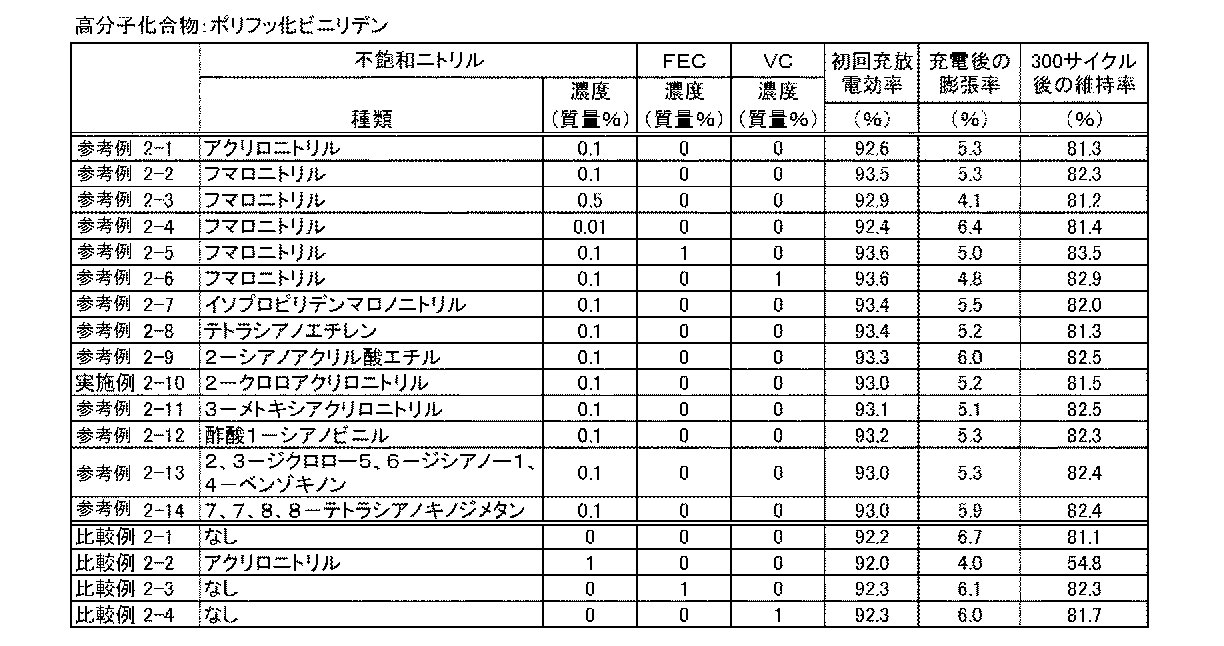
<実施例2−10、参考例2−1〜2−9、2−11〜2−14>
(参考例2−1)
セパレータの厚さを7μmとし、その両面にポリフッ化ビニリデンを2μmずつ塗布したセパレータを使用した以外は参考例1−1と同様にラミネート型電池を作製した。このとき、電解液とポリフッ化ビニリデンとの質量比は20:1であった。
< Example 2-10, Reference Examples 2-1 to 2-9, 2-11 to 2-14>
( Reference Example 2-1)
A laminate type battery was produced in the same manner as in Reference Example 1-1 except that the separator was 7 μm thick and a separator coated with 2 μm of polyvinylidene fluoride on both sides was used. At this time, the mass ratio of the electrolytic solution to polyvinylidene fluoride was 20: 1.
この電池を23℃環境下350mAで4.2Vを上限として3時間充電した後、140mAで3Vを下限として定電流放電した時の放電量の充電量に対する割合を表1に示す。
また、この電池を23℃環境下350mAで4.2Vを上限として3時間充電した後の電池厚みの変化を膨張率(%)として表1に示す。膨張率は充電前の電池厚みを分母とし、充電後に増加した厚みを分子として算出した値である。
さらに、23℃環境下700mAで4.2Vを上限として3時間充電した後、700mAで3Vを下限として定電流放電する事を300サイクル繰り返した時の放電容量維持率(%)を表2に示す。
Table 1 shows the ratio of the discharge amount to the charge amount when the battery was charged at 350 mA at 23 ° C. for 3 hours with 4.2 V as the upper limit and then discharged at a constant current with 140 mA at 3 V as the lower limit.
In addition, Table 1 shows the change in battery thickness after expansion for 3 hours under an environment of 23 ° C. and 350 mA at an upper limit of 4.2 V as an expansion rate (%). The expansion coefficient is a value calculated using the battery thickness before charging as the denominator and the thickness increased after charging as the numerator.
Furthermore, Table 2 shows the discharge capacity maintenance rate (%) when 300 cycles of repeating a constant current discharge at 700 mA with 3 V as the lower limit after charging for 3 hours at 700 mA in a 23 ° C. environment at 700 mA is shown in Table 2. .
(参考例2−2)
不飽和ニトリルとして、アクリロニトリルに換えてフマロニトリルを用いた以外は参考例2−1と同様にラミネート型電池を作製した。
( Reference Example 2-2)
A laminated battery was produced in the same manner as in Reference Example 2-1, except that fumaronitrile was used instead of acrylonitrile as the unsaturated nitrile.
(参考例2−3、2−4)
フマロニトリルの濃度をそれぞれ0.5質量%、0.01質量%とし、その分ジエチルカーボネートの量を増減した以外は参考例2−2と同様にラミネート型電池を作成した。
( Reference Examples 2-3, 2-4)
A laminate type battery was prepared in the same manner as in Reference Example 2-2 except that the concentration of fumaronitrile was 0.5% by mass and 0.01% by mass, respectively, and the amount of diethyl carbonate was increased or decreased accordingly.
(参考例2−5)
フルオロエチレンカーボネート(FEC)を1質量%添加し、その分ジエチルカーボネートの量を減少した以外は参考例2−2と同様にラミネート型電池を作成した。
( Reference Example 2-5)
A laminate type battery was prepared in the same manner as in Reference Example 2-2 except that 1% by mass of fluoroethylene carbonate (FEC) was added and the amount of diethyl carbonate was reduced accordingly.
(参考例2−6)
ビニレンカーボネート(VC)を1質量%添加し、その分ジエチルカーボネートの量を減少した以外は参考例2−2と同様にラミネート型電池を作成した。
( Reference Example 2-6)
A laminate type battery was prepared in the same manner as in Reference Example 2-2 except that 1% by mass of vinylene carbonate (VC) was added and the amount of diethyl carbonate was reduced accordingly.
(実施例2−10、参考例2−7〜2−9、2−11〜2−14)
不飽和ニトリルの種類を表2に示すものとした以外は参考例2−2と同様にラミネート型電池を作成した。
( Example 2-10, Reference Examples 2-7 to 2-9, 2-11 to 2-14)
A laminate type battery was prepared in the same manner as in Reference Example 2-2 except that the type of unsaturated nitrile was as shown in Table 2.
(比較例2−1)
不飽和ニトリルを混合せず、その分ジエチルカーボネートを増量した以外は参考例2−1と同様にラミネート型電池を作成した。
(Comparative Example 2-1)
A laminated battery was prepared in the same manner as in Reference Example 2-1, except that the unsaturated nitrile was not mixed and diethyl carbonate was increased accordingly.
(比較例2−2)
アクリロニトリルの濃度を1質量%とし、その分ジエチルカーボネートを減量した以外は参考例2−1と同様にラミネート型電池を作成した。
(Comparative Example 2-2)
A laminate type battery was prepared in the same manner as in Reference Example 2-1, except that the concentration of acrylonitrile was 1% by mass and the amount of diethyl carbonate was reduced accordingly.
(比較例2−3)
不飽和ニトリルを混合せず、その分ジエチルカーボネートを増量した以外は参考例2−5と同様にラミネート型電池を作成した。
(Comparative Example 2-3)
A laminate type battery was prepared in the same manner as in Reference Example 2-5 except that the unsaturated nitrile was not mixed and diethyl carbonate was increased accordingly.
(比較例2−4)
不飽和ニトリルを混合せず、その分ジエチルカーボネートを増量した以外は参考例2−6と同様にラミネート型電池を作成した。
(Comparative Example 2-4)
A laminated battery was prepared in the same manner as in Reference Example 2-6 except that the unsaturated nitrile was not mixed and diethyl carbonate was increased by that amount.
実施例2−10、参考例2−1〜2−9、2−11〜2−14、および比較例2−1〜2−4で作製したラミネート型電池の物性を評価した結果を表2に示す。 Table 2 shows the results of evaluating the physical properties of the laminate type batteries prepared in Example 2-10, Reference Examples 2-1 to 2-9 , 2-11 to 2-14, and Comparative Examples 2-1 to 2-4. Show.
表2に示したように、不飽和ニトリル(アクリロニトリル、フマロニトリル、イソプロピリデンマロノニトリル、テトラシアノエチレン、2−シアノアクリル酸エチル、2−クロロアクリロニトリル、3−メトキシアクリロニトリル、酢酸1―シアノビニル、2,3−ジクロロー5,6−ジシアノー1,4−ベンゾキノン、7,7,8,8−テトラシアノキノジメタン)と電解液により膨潤する高分子化合物(ポリフッ化ビニリデン)と電解液に含む実施例2−10、参考例2−1〜2−4、2−7〜2−9、2−11〜2−14は、ポリフッ化ビニリデンを電解液に含まない参考例1−1と比較して、充電時の電池膨張率が減少した。このことから、不飽和ニトリルとともに、電解液により膨潤する高分子化合物を電解液に使用することにより、充電時の電池膨張を抑制する効果が向上することが分かった。 As shown in Table 2, unsaturated nitriles (acrylonitrile, fumaronitrile, isopropylidenemalononitrile, tetracyanoethylene, ethyl 2-cyanoacrylate, 2-chloroacrylonitrile, 3-methoxyacrylonitrile, 1-cyanovinyl acetate, 2,3 -Dichloro-5,6-dicyano-1,4-benzoquinone, 7,7,8,8-tetracyanoquinodimethane), a polymer compound (polyvinylidene fluoride) swelled by the electrolyte, and Example 2- 10, Reference Examples 2-1 to 2-4, 2-7 to 2-9, 2-11 to 2-14 are compared with Reference Example 1-1 in which polyvinylidene fluoride is not included in the electrolytic solution. The battery expansion rate decreased. From this, it was found that the use of a polymer compound that swells with the electrolyte together with the unsaturated nitrile in the electrolyte improves the effect of suppressing battery expansion during charging.
また、アクリロニトリルを1質量%含む電解液を使用した比較例2−2は、0.1質量%含有する参考例2−1や、アクリロニトリルを含有しない電解液の比較例2−1よりも充電時の電池膨張率は向上したが、初回充電効率が低下し、300サイクル後の放電容量維持率は大幅に低下した。これより、電解液に過剰量の不飽和ニトリルを含有すると、充電効率やサイクル特性が低下することが分かった。 Further, Comparative Example 2-2 using an electrolytic solution containing 1% by mass of acrylonitrile is more charged than Reference Example 2-1 containing 0.1% by mass or Comparative Example 2-1 of an electrolytic solution not containing acrylonitrile. However, the initial charge efficiency was reduced, and the discharge capacity retention rate after 300 cycles was greatly reduced. From this, it has been found that when an excess amount of unsaturated nitrile is contained in the electrolytic solution, charging efficiency and cycle characteristics are lowered.
電解液における不飽和ニトリルの濃度を変化させた参考例2−2〜2−4と比較例2−1とを比較すると、0.01質量%の参考例2−4は、比較例2−1よりも全ての特性が向上し、0.1質量%の参考例2−2ではさらに向上した。0.5質量%の参考例2−3になると、膨張率はさらに向上したが、初回充放電効率や300サイクル後の放電容量維持率は参考例2−2よりも低下した。これらの結果から、電解液における不飽和ニトリルの濃度が0.01〜0.5質量%の範囲内であれば、良好な結果が得られることが分かった。 When Reference Examples 2-2 to 2-4 in which the concentration of the unsaturated nitrile in the electrolytic solution was changed and Comparative Example 2-1 were compared, 0.01% by mass of Reference Example 2-4 was found to be Comparative Example 2-1. All the characteristics were improved more, and in the reference example 2-2 of 0.1% by mass, the characteristics were further improved. In Reference Example 2-3 of 0.5 mass%, the expansion rate was further improved, but the initial charge / discharge efficiency and the discharge capacity retention rate after 300 cycles were lower than those in Reference Example 2-2. From these results, it was found that good results can be obtained when the concentration of the unsaturated nitrile in the electrolytic solution is in the range of 0.01 to 0.5 mass%.
フマロニトリルに加えて、フルオロエチレンカーボネートを電解液に混合した参考例2−5は、フルオロエチレンカーボネートを含むがフマロニトリルを含まない比較例2−3や、フマロニトリルを含むがフルオロエチレンカーボネートを含まない参考例2−2と比較して、初回充電効率が向上し、充電時の電池膨張率が減少し、300サイクル後の放電容量維持率も向上した。これらの結果から、不飽和ニトリルとともにハロゲン化炭酸エステルを電解液に含有することにより、電池膨張を抑制し、サイクル特性をより向上できることが分かった。 Reference Example 2-5 in which fluoroethylene carbonate is mixed with the electrolyte in addition to fumaronitrile is Comparative Example 2-3 containing fluoroethylene carbonate but not containing fumaronitrile, or Reference Example containing fumaronitrile but not containing fluoroethylene carbonate Compared to 2-2, the initial charge efficiency was improved, the battery expansion rate during charging was reduced, and the discharge capacity retention rate after 300 cycles was also improved. From these results, it was found that by containing a halogenated carbonate in the electrolyte together with the unsaturated nitrile, battery expansion can be suppressed and cycle characteristics can be further improved.
フマロニトリルに加えて、ビニレンカーボネートを電解液に混合した参考例2−6は、ビニレンカーボネートを含むがフマロニトリルを含まない比較例2−4や、フマロニトリルを含むがビニレンカーボネートを含まない参考例2−2と比較して、初回充電効率が向上し、充電時の電池膨張率が減少し、300サイクル後の放電容量維持率も向上した。これらの結果から、不飽和ニトリルとともに炭素−炭素多重結合を有する炭酸エステルを電解液に含有することにより、電池膨張を抑制し、サイクル特性をより向上できることが分かった。 Reference Example 2-6 in which vinylene carbonate was mixed with the electrolyte in addition to fumaronitrile included Comparative Example 2-4 containing vinylene carbonate but not containing fumaronitrile, or Reference Example 2-2 containing fumaronitrile but no vinylene carbonate. As compared with, the initial charge efficiency was improved, the battery expansion rate during charging was reduced, and the discharge capacity retention rate after 300 cycles was also improved. From these results, it was found that by containing a carbonate ester having a carbon-carbon multiple bond together with an unsaturated nitrile in the electrolyte, battery expansion can be suppressed and cycle characteristics can be further improved.
以上、実施例を挙げて本発明を説明したが、本発明は上記実施例に限定されるものではなく、種々変形が可能であることは言うまでもない。 While the present invention has been described with reference to the embodiments, it is needless to say that the present invention is not limited to the above embodiments and can be variously modified.
20…巻回電極体、23…正極、23A…正極集電体、23B…正極活物質層、24…負極、24A…負極集電体、24B…負極活物質層、25…セパレータ、21…正極リード、22…負極リード、26…電解質層、27…保護テープ、30…外装部材、31…密着フィルム。
DESCRIPTION OF
Claims (14)
前記非水電解液が下式(1)で表される炭素−炭素多重結合を有する不飽和ニトリルの少なくとも1種を、0.01〜0.5質量%含有する非水電解液二次電池。
Carbon the nonaqueous electrolyte solution you express by the following formula (1) - at least one of the non-aqueous electrolyte secondary battery you containing 0.01 to 0.5 wt% of an unsaturated nitrile with carbon multiple bonds .
Priority Applications (1)
| Application Number | Priority Date | Filing Date | Title |
|---|---|---|---|
| JP2007295665A JP5163065B2 (en) | 2007-11-14 | 2007-11-14 | Non-aqueous electrolyte secondary battery and non-aqueous electrolyte composition |
Applications Claiming Priority (1)
| Application Number | Priority Date | Filing Date | Title |
|---|---|---|---|
| JP2007295665A JP5163065B2 (en) | 2007-11-14 | 2007-11-14 | Non-aqueous electrolyte secondary battery and non-aqueous electrolyte composition |
Publications (2)
| Publication Number | Publication Date |
|---|---|
| JP2009123499A JP2009123499A (en) | 2009-06-04 |
| JP5163065B2 true JP5163065B2 (en) | 2013-03-13 |
Family
ID=40815442
Family Applications (1)
| Application Number | Title | Priority Date | Filing Date |
|---|---|---|---|
| JP2007295665A Expired - Fee Related JP5163065B2 (en) | 2007-11-14 | 2007-11-14 | Non-aqueous electrolyte secondary battery and non-aqueous electrolyte composition |
Country Status (1)
| Country | Link |
|---|---|
| JP (1) | JP5163065B2 (en) |
Families Citing this family (10)
| Publication number | Priority date | Publication date | Assignee | Title |
|---|---|---|---|---|
| KR101178554B1 (en) | 2009-07-09 | 2012-08-30 | 주식회사 엘지화학 | Non-aqueous electrolyte solution for lithium secondary battery and lithium secondary battery comprising the same |
| US8795904B2 (en) * | 2010-05-13 | 2014-08-05 | The United States Of America As Represented By The Secretary Of The Army | Nonaqueous electrolyte solvents and additives |
| WO2012029386A1 (en) * | 2010-09-02 | 2012-03-08 | 日本電気株式会社 | Secondary battery |
| JP5921982B2 (en) * | 2012-07-27 | 2016-05-24 | 富士フイルム株式会社 | Non-aqueous secondary battery electrolyte and secondary battery |
| FR3038455B1 (en) * | 2015-07-01 | 2020-03-13 | Renault S.A.S. | COMPOUND USED AS AN ADDITIVE IN AN ELECTROLYTE FOR ION CIRCULATION BATTERY |
| JP6652013B2 (en) * | 2015-09-24 | 2020-02-19 | 三菱ケミカル株式会社 | Non-aqueous electrolyte and non-aqueous electrolyte secondary battery using the same |
| JP2019200880A (en) * | 2018-05-15 | 2019-11-21 | 日本電信電話株式会社 | Lithium secondary battery |
| CN110797576B (en) * | 2019-11-08 | 2020-11-27 | 广州天赐高新材料股份有限公司 | High-voltage lithium ion battery electrolyte and lithium ion battery |
| KR20210070609A (en) * | 2019-12-05 | 2021-06-15 | 주식회사 엘지에너지솔루션 | Non-aqueous electrolyte for lithium secondary battery and lithium secondary battery comprising the same |
| CN113140797B (en) * | 2021-04-25 | 2022-09-20 | 湖州师范学院 | Non-aqueous electrolyte with polynitrile compound and lithium ion battery |
Family Cites Families (8)
| Publication number | Priority date | Publication date | Assignee | Title |
|---|---|---|---|---|
| DE3611123A1 (en) * | 1986-04-03 | 1987-10-08 | Varta Batterie | WATER-FREE ORGANIC ELECTROLYTE |
| JPH08222268A (en) * | 1995-02-10 | 1996-08-30 | Matsushita Electric Ind Co Ltd | Electrolyte for lithium secondary battery |
| JP2000021444A (en) * | 1998-06-30 | 2000-01-21 | Shin Kobe Electric Mach Co Ltd | Nonaqueous electrolyte secondary battery |
| JP3718467B2 (en) * | 2001-03-28 | 2005-11-24 | 株式会社東芝 | Non-aqueous electrolyte and non-aqueous electrolyte secondary battery |
| JP5282346B2 (en) * | 2001-09-13 | 2013-09-04 | 三菱化学株式会社 | Non-aqueous electrolyte secondary battery |
| KR100987376B1 (en) * | 2003-08-27 | 2010-10-12 | 삼성에스디아이 주식회사 | Binder and electrode for lithium battery, and lithium battery using the same |
| JP4893038B2 (en) * | 2006-03-17 | 2012-03-07 | 株式会社Gsユアサ | Nonaqueous electrolyte secondary battery |
| JP2008166271A (en) * | 2006-12-06 | 2008-07-17 | Mitsubishi Chemicals Corp | Nonaqueous electrolyte solution and nonaqueous electrolyte secondary battery |
-
2007
- 2007-11-14 JP JP2007295665A patent/JP5163065B2/en not_active Expired - Fee Related
Also Published As
| Publication number | Publication date |
|---|---|
| JP2009123499A (en) | 2009-06-04 |
Similar Documents
| Publication | Publication Date | Title |
|---|---|---|
| JP4992921B2 (en) | Non-aqueous electrolyte secondary battery | |
| JP5163065B2 (en) | Non-aqueous electrolyte secondary battery and non-aqueous electrolyte composition | |
| JP4655118B2 (en) | Non-aqueous electrolyte battery and non-aqueous electrolyte composition | |
| JP5181430B2 (en) | Secondary battery | |
| JP5045882B2 (en) | Electrolyte and battery | |
| JP2009152133A (en) | Nonaqueous electrolyte secondary battery | |
| JP5050379B2 (en) | Secondary battery | |
| JP2010262905A (en) | Nonaqueous electrolytic solution battery | |
| JP2009302022A (en) | Nonaqueous electrolyte secondary battery | |
| JP2009158460A (en) | Nonaqueous electrolyte secondary battery | |
| JP2008066062A (en) | Non-aqueous electrolyte composition and non-aqueous electrolyte secondary battery | |
| JP5493516B2 (en) | Electrode and battery having the same | |
| JP2008218381A (en) | Nonaqueous electrolyte battery | |
| JP2009123497A (en) | Nonaqueous electrolyte composition and nonaqueous electrolyte battery | |
| JP2009123498A (en) | Nonaqueous electrolyte composition and nonaqueous electrolyte battery | |
| JP2008305772A (en) | Nonaqueous electrolyte solution secondary battery and nonaqueous electrolyte solution | |
| JP2008210769A (en) | Nonaqueous electrolyte battery | |
| JP2009252645A (en) | Non-aqueous electrolyte secondary battery and non-aqueous electrolyte composition | |
| JP2009211941A (en) | Nonaqueous electrolyte secondary battery | |
| JP2007134245A (en) | Electrolyte solution and battery | |
| JP2009099448A (en) | Non-aqueous electrolytic liquid secondary battery and non-aqueous electrolytic liquid composition | |
| JP2009093843A (en) | Nonaqueous electrolyte secondary battery | |
| JP2008305771A (en) | Nonaqueous solution battery | |
| JP2009134943A (en) | Nonaqueous electrolyte battery | |
| JP2011249152A (en) | Lithium battery electrode active material composition and lithium battery |
Legal Events
| Date | Code | Title | Description |
|---|---|---|---|
| RD03 | Notification of appointment of power of attorney |
Free format text: JAPANESE INTERMEDIATE CODE: A7423 Effective date: 20090723 |
|
| RD04 | Notification of resignation of power of attorney |
Free format text: JAPANESE INTERMEDIATE CODE: A7424 Effective date: 20090825 |
|
| A621 | Written request for application examination |
Free format text: JAPANESE INTERMEDIATE CODE: A621 Effective date: 20100812 |
|
| A977 | Report on retrieval |
Free format text: JAPANESE INTERMEDIATE CODE: A971007 Effective date: 20120810 |
|
| A131 | Notification of reasons for refusal |
Free format text: JAPANESE INTERMEDIATE CODE: A131 Effective date: 20120821 |
|
| A521 | Request for written amendment filed |
Free format text: JAPANESE INTERMEDIATE CODE: A523 Effective date: 20121011 |
|
| TRDD | Decision of grant or rejection written | ||
| A01 | Written decision to grant a patent or to grant a registration (utility model) |
Free format text: JAPANESE INTERMEDIATE CODE: A01 Effective date: 20121120 |
|
| A61 | First payment of annual fees (during grant procedure) |
Free format text: JAPANESE INTERMEDIATE CODE: A61 Effective date: 20121203 |
|
| FPAY | Renewal fee payment (event date is renewal date of database) |
Free format text: PAYMENT UNTIL: 20151228 Year of fee payment: 3 |
|
| FPAY | Renewal fee payment (event date is renewal date of database) |
Free format text: PAYMENT UNTIL: 20151228 Year of fee payment: 3 |
|
| LAPS | Cancellation because of no payment of annual fees |