JP5162767B2 - Clutch control device - Google Patents
Clutch control device Download PDFInfo
- Publication number
- JP5162767B2 JP5162767B2 JP2008088032A JP2008088032A JP5162767B2 JP 5162767 B2 JP5162767 B2 JP 5162767B2 JP 2008088032 A JP2008088032 A JP 2008088032A JP 2008088032 A JP2008088032 A JP 2008088032A JP 5162767 B2 JP5162767 B2 JP 5162767B2
- Authority
- JP
- Japan
- Prior art keywords
- clutch
- control amount
- main shaft
- connection
- clutch control
- Prior art date
- Legal status (The legal status is an assumption and is not a legal conclusion. Google has not performed a legal analysis and makes no representation as to the accuracy of the status listed.)
- Active
Links
Images


Classifications
-
- F—MECHANICAL ENGINEERING; LIGHTING; HEATING; WEAPONS; BLASTING
- F16—ENGINEERING ELEMENTS AND UNITS; GENERAL MEASURES FOR PRODUCING AND MAINTAINING EFFECTIVE FUNCTIONING OF MACHINES OR INSTALLATIONS; THERMAL INSULATION IN GENERAL
- F16D—COUPLINGS FOR TRANSMITTING ROTATION; CLUTCHES; BRAKES
- F16D48/00—External control of clutches
- F16D48/06—Control by electric or electronic means, e.g. of fluid pressure
- F16D48/066—Control of fluid pressure, e.g. using an accumulator
-
- F—MECHANICAL ENGINEERING; LIGHTING; HEATING; WEAPONS; BLASTING
- F16—ENGINEERING ELEMENTS AND UNITS; GENERAL MEASURES FOR PRODUCING AND MAINTAINING EFFECTIVE FUNCTIONING OF MACHINES OR INSTALLATIONS; THERMAL INSULATION IN GENERAL
- F16D—COUPLINGS FOR TRANSMITTING ROTATION; CLUTCHES; BRAKES
- F16D2500/00—External control of clutches by electric or electronic means
- F16D2500/30—Signal inputs
- F16D2500/302—Signal inputs from the actuator
- F16D2500/3024—Pressure
-
- F—MECHANICAL ENGINEERING; LIGHTING; HEATING; WEAPONS; BLASTING
- F16—ENGINEERING ELEMENTS AND UNITS; GENERAL MEASURES FOR PRODUCING AND MAINTAINING EFFECTIVE FUNCTIONING OF MACHINES OR INSTALLATIONS; THERMAL INSULATION IN GENERAL
- F16D—COUPLINGS FOR TRANSMITTING ROTATION; CLUTCHES; BRAKES
- F16D2500/00—External control of clutches by electric or electronic means
- F16D2500/30—Signal inputs
- F16D2500/304—Signal inputs from the clutch
- F16D2500/30406—Clutch slip
-
- F—MECHANICAL ENGINEERING; LIGHTING; HEATING; WEAPONS; BLASTING
- F16—ENGINEERING ELEMENTS AND UNITS; GENERAL MEASURES FOR PRODUCING AND MAINTAINING EFFECTIVE FUNCTIONING OF MACHINES OR INSTALLATIONS; THERMAL INSULATION IN GENERAL
- F16D—COUPLINGS FOR TRANSMITTING ROTATION; CLUTCHES; BRAKES
- F16D2500/00—External control of clutches by electric or electronic means
- F16D2500/30—Signal inputs
- F16D2500/306—Signal inputs from the engine
- F16D2500/3067—Speed of the engine
-
- F—MECHANICAL ENGINEERING; LIGHTING; HEATING; WEAPONS; BLASTING
- F16—ENGINEERING ELEMENTS AND UNITS; GENERAL MEASURES FOR PRODUCING AND MAINTAINING EFFECTIVE FUNCTIONING OF MACHINES OR INSTALLATIONS; THERMAL INSULATION IN GENERAL
- F16D—COUPLINGS FOR TRANSMITTING ROTATION; CLUTCHES; BRAKES
- F16D2500/00—External control of clutches by electric or electronic means
- F16D2500/30—Signal inputs
- F16D2500/308—Signal inputs from the transmission
- F16D2500/3081—Signal inputs from the transmission from the input shaft
- F16D2500/30816—Speed of the input shaft
-
- F—MECHANICAL ENGINEERING; LIGHTING; HEATING; WEAPONS; BLASTING
- F16—ENGINEERING ELEMENTS AND UNITS; GENERAL MEASURES FOR PRODUCING AND MAINTAINING EFFECTIVE FUNCTIONING OF MACHINES OR INSTALLATIONS; THERMAL INSULATION IN GENERAL
- F16D—COUPLINGS FOR TRANSMITTING ROTATION; CLUTCHES; BRAKES
- F16D2500/00—External control of clutches by electric or electronic means
- F16D2500/50—Problem to be solved by the control system
- F16D2500/502—Relating the clutch
- F16D2500/50245—Calibration or recalibration of the clutch touch-point
- F16D2500/50251—During operation
- F16D2500/50254—Brake actuated
Description
本発明は、クラッチ制御装置に係り、特に、クラッチの入力側回転体および出力側回転体の回転速度を計測することでクラッチのつながり始めを検出できるクラッチ制御装置に関する。 The present invention relates to a clutch control device, and more particularly to a clutch control device that can detect the start of clutch engagement by measuring the rotational speeds of an input-side rotator and an output-side rotator of a clutch.
従来から、摩擦板(クラッチ板)の摩擦力によって動力源の回転駆動力を駆動輪に伝達するクラッチを、アクチュエータで駆動制御するようにしたクラッチ装置が知られている。このようなクラッチ装置では、例えば、クラッチ板が摩耗して薄くなった場合には、アクチュエータの駆動量が同じでも、同じ摩擦力を得られなくなる可能性がある。このような課題は、例えば、離間したクラッチ板同士が当接するまでの移動量を検知し、この移動量の増加に応じてアクチュエータの駆動量を大きくすることで解決できる。 2. Description of the Related Art Conventionally, a clutch device is known in which a clutch that transmits a rotational driving force of a power source to a driving wheel by a friction force of a friction plate (clutch plate) is controlled by an actuator. In such a clutch device, for example, when the clutch plate is worn and thinned, there is a possibility that the same frictional force cannot be obtained even if the drive amount of the actuator is the same. Such a problem can be solved, for example, by detecting the amount of movement until the separated clutch plates come into contact with each other and increasing the drive amount of the actuator in accordance with the increase in the amount of movement.
特許文献1には、アクチュエータによって変位される部材の位置に基づいて、クラッチ板同士が当接するまでの移動量を検知するようにした構成が開示されている。
しかしながら、特許文献1に記載された構成では、アクチュエータの駆動量に基づいてクラッチ板の摩耗度を推測するものであるので、クラッチ板の摩擦特性や、クラッチを潤滑するオイルの特性が変わることによる摩擦力の変化を検知することはできなかった。また、クラッチを接続させるための押圧力を、クラッチスプリング等の弾性部材で得るのではなく、アクチュエータの駆動力や、アクチュエータで制御される油圧によって得るようにした構成では、特に、クラッチ板同士が接触した後の押圧力によって摩擦力が変化する。したがって、より適切なクラッチ制御を行うためには、クラッチが実際につながり始めるタイミングを検知したいという要望があった。 However, in the configuration described in Patent Document 1, since the degree of wear of the clutch plate is estimated based on the drive amount of the actuator, the friction characteristics of the clutch plate and the characteristics of the oil that lubricates the clutch are changed. A change in frictional force could not be detected. Further, in the configuration in which the pressing force for connecting the clutch is not obtained by an elastic member such as a clutch spring but by the driving force of the actuator or the hydraulic pressure controlled by the actuator, the clutch plates are particularly The frictional force changes depending on the pressing force after contact. Therefore, in order to perform more appropriate clutch control, there is a demand for detecting the timing at which the clutch actually starts to be connected.
本発明の目的は、上記従来技術の課題を解決し、クラッチの入力側回転体および出力側回転体の回転速度を計測することでクラッチのつながり始めを検出できるクラッチ制御装置を提供することにある。 An object of the present invention is to provide a clutch control device that solves the above-described problems of the prior art and can detect the start of clutch engagement by measuring the rotational speeds of the input-side rotating body and the output-side rotating body of the clutch. .
前記目的を達成するために、本発明は、車両の動力源から駆動輪へ伝達される回転駆動力を断接するクラッチのクラッチ制御装置において、前記クラッチは、該クラッチが接続された状態で同期回転する入力側回転体および出力側回転体を有し、前記入力側回転体の回転速度を検出する入力側回転速度検出手段と、前記出力側回転体の回転速度を検出する出力側回転速度検出手段と、前記クラッチ制御量を制御するクラッチ制御手段と、前記クラッチの切断中に前記出力側回転体を一旦停止させるブレーキ手段と、前記クラッチ制御量を検出するクラッチ制御量検出手段と、前記入力側回転体と出力側回転体との回転速度差が所定値以下となった場合に前記クラッチのつながり始めを検出するつながり始め検出手段と、前記つながり始めにおける前記クラッチ制御量を検出するつながり始め制御量検出手段と、前記出力側回転体を一旦停止させた後に前記つながり始めが検出された時点での前記クラッチ制御量に基づいて、前記クラッチの補正制御量を導出するクラッチ補正制御量導出手段とを具備し、前記クラッチ制御手段に対し、前記補正制御量に基づいて前記クラッチ制御量をフィードバック制御する点に第1の特徴がある。 In order to achieve the above object, the present invention provides a clutch control device for a clutch that connects and disconnects a rotational driving force transmitted from a power source of a vehicle to a driving wheel. The clutch rotates synchronously with the clutch connected. An input side rotational speed detection means for detecting the rotational speed of the input side rotational body, and an output side rotational speed detection means for detecting the rotational speed of the output side rotational body. Clutch control means for controlling the clutch control amount, brake means for temporarily stopping the output side rotating body during disengagement of the clutch, clutch control amount detection means for detecting the clutch control amount, and the input side A connection start detecting means for detecting the start of connection of the clutch when a difference in rotational speed between the rotary body and the output side rotary body is a predetermined value or less; And a clutch start control amount detecting means for detecting the clutch control amount, and the clutch correction control based on the clutch control amount at the time when the start of connection is detected after the output side rotating body is temporarily stopped. A clutch correction control amount deriving unit for deriving the amount is provided, and the clutch control unit is feedback-controlled based on the correction control amount with respect to the clutch control unit.
また、前記ブレーキ手段は、前記出力側回転体を一旦停止させた後も所定時間ブレーキ動作を継続する点に第2の特徴がある。 Further, the brake means has a second feature in that the brake operation is continued for a predetermined time after the output side rotating body is once stopped.
また、前記クラッチは油圧式であり、前記つながり始め制御量検出手段は、前記クラッチに生じる油圧に基づいて前記クラッチ制御量を導出する点に第3の特徴がある。 The clutch is hydraulic, and the third feature is that the connection start control amount detection means derives the clutch control amount based on the hydraulic pressure generated in the clutch.
また、前記クラッチは、油圧供給源から供給される油圧で駆動される油圧式であり、前記油圧供給源とクラッチとの間に設けられて、前記クラッチに供給する作動油の流量を制御するアクチュエータを備え、前記つながり始め制御量検出手段は、前記アクチュエータの駆動電流値に基づいて前記クラッチ制御量を導出する点に第4の特徴がある。 The clutch is a hydraulic type driven by a hydraulic pressure supplied from a hydraulic pressure supply source, and is provided between the hydraulic pressure supply source and the clutch, and is an actuator that controls a flow rate of hydraulic oil supplied to the clutch. There is a fourth feature in that the connection start control amount detection means derives the clutch control amount based on the drive current value of the actuator.
また、前記回転駆動力を所定の変速比で前記駆動輪に伝達する有段変速機を備え、前記クラッチは、第1クラッチおよび第2クラッチからなるツインクラッチであると共に、前記有段変速機の変速動作毎に前記ツインクラッチの断接状態を交互に切り換えるように構成されており、前記有段変速機は、奇数段ギヤまたは偶数段ギヤのうち、前記第1クラッチまたは第2クラッチが切断されることで前記回転駆動力を伝達していない側のギヤをニュートラル状態にすることができるように構成されており、前記つながり始め検出手段は、前記第1クラッチまたは第2クラッチのうちの切断されている側に対して、前記つながり始めの検出を行う点に第5の特徴がある。 A stepped transmission that transmits the rotational driving force to the drive wheels at a predetermined gear ratio; the clutch is a twin clutch including a first clutch and a second clutch; The twin clutch is alternately connected / disconnected for each speed change operation, and the stepped transmission is configured such that the first clutch or the second clutch of the odd gear or the even gear is disengaged. Thus, the gear on the side not transmitting the rotational driving force can be set to a neutral state, and the connection start detecting means is disconnected from the first clutch or the second clutch. There is a fifth feature in that the connection start detection is performed on the connected side.
また、前記つながり始め検出手段は、前記つながり始めの検出を所定周期毎に行う点に第6の特徴がある。 Further, the connection start detecting means has a sixth feature in that the connection start detection is performed at predetermined intervals.
また、前記クラッチ補正制御量導出手段は、前記つながり始めが検出された時のクラッチ制御量と前記補正制御量との関係を予め規定したデータテーブルに基づいて、前記補正制御量を導出する点に第7の特徴がある。 Further, the clutch correction control amount deriving means derives the correction control amount based on a data table in which a relationship between the clutch control amount and the correction control amount when the start of connection is detected is defined in advance. There is a seventh feature.
さらに、前記クラッチ制御手段は、前記つながり始め状態が検出された時のクラッチ制御量が所定値を超えると、警告手段によって警告を発する点に第8の特徴がある。 Further, the clutch control means has an eighth feature in that a warning is issued by a warning means when the clutch control amount when the connection start state is detected exceeds a predetermined value.
第1の特徴によれば、クラッチの切断中に、ブレーキ手段によってクラッチの出力側回転体を一旦停止させた後に、入力側回転体と出力側回転体との回転速度差が所定値以下になることでクラッチのつながり始めを検出し、さらに、つながり始めが検出された時点でのクラッチ制御量に基づいてクラッチの補正制御量を導出して、この補正制御量に基づいてクラッチをフィードバック制御するので、クラッチが実際につながり始めるタイミングを検出することで、クラッチ板の摩擦特性や潤滑油の特性が変わってクラッチに生じる摩擦力が変化した場合でも、適切な制御補正量を適用してクラッチをフィードバック制御することができる。また、クラッチを切断した状態で出力側回転体と入力側回転体とが連れ回りしやすい場合でも、出力側回転体を一旦停止させることで、入力側回転体と出力側回転体との回転速度差が所定値以下になるタイミングを確実に検知することが可能となる。 According to the first feature, after the clutch is disengaged, the rotational speed difference between the input-side rotator and the output-side rotator becomes equal to or less than a predetermined value after the clutch output-side rotator is temporarily stopped by the brake means. Therefore, the clutch engagement start is detected, and the clutch correction control amount is derived based on the clutch control amount when the connection start is detected, and the clutch is feedback-controlled based on the correction control amount. By detecting the timing when the clutch actually starts to be connected, even if the friction force generated in the clutch changes due to the change in the friction characteristics of the clutch plate or the characteristics of the lubricant, the clutch is fed back by applying an appropriate control correction amount. Can be controlled. Even if the output-side rotator and the input-side rotator easily rotate with the clutch disengaged, the rotational speed of the input-side rotator and the output-side rotator is temporarily stopped by temporarily stopping the output-side rotator. It is possible to reliably detect the timing when the difference becomes equal to or less than the predetermined value.
また、主軸とカウンタ軸との間に複数の歯車対が配設されたドグクラッチ式の有段変速機において、主軸上にクラッチが配設され、この主軸に出力側回転体が結合されている場合には、ブレーキ手段で主軸の回転を停止させることで、カウンタ軸の回転が停止している間にニュートラルから1速に変速する際の変速ショックを低減できる。また、ドグクラッチの相対回転速度が小さくなることによって、噛み合い音も低減できる。 Further, in a dog clutch type stepped transmission in which a plurality of gear pairs are disposed between the main shaft and the counter shaft, a clutch is disposed on the main shaft, and an output side rotating body is coupled to the main shaft. First, by stopping the rotation of the main shaft by the brake means, it is possible to reduce the shift shock when shifting from the neutral to the first speed while the rotation of the counter shaft is stopped. Further, the meshing noise can be reduced by reducing the relative rotational speed of the dog clutch.
第2の特徴によれば、ブレーキ手段は、出力側回転体を一旦停止させた後も所定時間ブレーキ動作を継続するので、クラッチの潤滑油の粘性やフリクション等によって、主軸を一旦停止させた後でも出力側回転体が連れ回りしようとする場合、連れ回りを防止してクラッチのつながり始めを検知することができる。 According to the second feature, the brake means continues the brake operation for a predetermined time after the output-side rotating body is once stopped. Therefore, after the main shaft is temporarily stopped due to the viscosity of the lubricating oil of the clutch, friction, or the like. However, when the output-side rotator tries to rotate, it is possible to prevent the rotation and detect the start of clutch engagement.
第3の特徴によれば、クラッチは油圧式であり、つながり始め制御量検出手段は、クラッチに生じる油圧に基づいてクラッチ制御量を導出するので、クラッチに生じる油圧を計測する油圧検出手段を用いて、クラッチの制御量を導出することが可能となる。 According to the third feature, the clutch is hydraulic, and the connection start control amount detecting means derives the clutch control amount based on the oil pressure generated in the clutch, so that the oil pressure detecting means for measuring the oil pressure generated in the clutch is used. Thus, the control amount of the clutch can be derived.
第4の特徴によれば、クラッチは、油圧供給源から供給される油圧で駆動される油圧式であり、油圧供給源とクラッチとの間に設けられて、クラッチに供給する作動油の流量を制御するアクチュエータを備え、つながり始め制御量検出手段は、アクチュエータの駆動電流値に基づいてクラッチ制御量を導出するので、アクチュエータの駆動電流値に基づいて、クラッチ制御量を導出することが可能となる。 According to the fourth feature, the clutch is a hydraulic type driven by a hydraulic pressure supplied from a hydraulic pressure supply source, and is provided between the hydraulic pressure supply source and the clutch to control the flow rate of hydraulic oil supplied to the clutch. The connected control amount detection means includes the actuator to be controlled, and derives the clutch control amount based on the drive current value of the actuator. Therefore, the clutch control amount can be derived based on the drive current value of the actuator. .
第5の特徴によれば、回転駆動力を所定の変速比で駆動輪に伝達する有段変速機を備え、クラッチは第1クラッチおよび第2クラッチからなるツインクラッチであり、つながり始め検出手段は、第1クラッチまたは第2クラッチのうちの切断されている側に対してつながり始めの検出を行うので、車両の走行中においても両クラッチのつながり始め状態を検知することができる。これにより、走行中にクラッチのつながり始め状態が変化した場合でも、クラッチの制御補正量を随時更新することが可能となる。 According to a fifth feature, the vehicle includes a stepped transmission that transmits the rotational driving force to the drive wheels at a predetermined speed ratio, the clutch is a twin clutch composed of a first clutch and a second clutch, Since the start of connection is detected for the disconnected side of the first clutch or the second clutch, it is possible to detect the connection start state of both clutches even while the vehicle is running. Thus, even when the clutch engagement start state changes during traveling, the clutch control correction amount can be updated as needed.
第6の特徴によれば、つながり始め検出手段は、つながり始めの検出を所定周期毎に行うので、所定周期毎にフィードバック制御量が更新されて、より適切なクラッチ制御が可能となる。 According to the sixth feature, the connection start detection means detects the start of connection every predetermined cycle, so that the feedback control amount is updated every predetermined cycle, thereby enabling more appropriate clutch control.
第7の特徴によれば、クラッチ補正制御量導出手段は、つながり始めが検出された時のクラッチ制御量と補正制御量との関係を予め規定したデータテーブルに基づいて、補正制御量を導出するので、クラッチの補正制御量を容易に導出することができる。 According to the seventh feature, the clutch correction control amount deriving unit derives the correction control amount based on a data table in which the relationship between the clutch control amount and the correction control amount when the start of connection is detected is defined in advance. Therefore, the clutch correction control amount can be easily derived.
第8の特徴によれば、クラッチ制御手段は、つながり始め状態が検出された時のクラッチ制御量が所定値を超えると警告手段によって警告を発するので、クラッチがつながり始めるまでの制御量が大きくなったことを使用者に認識させることが可能となる。これにより、摩耗したクラッチ板を交換する等の対処を使用者に促すことができる。 According to the eighth feature, the clutch control means issues a warning by the warning means when the clutch control amount when the engagement start state is detected exceeds a predetermined value, so that the control amount until the clutch starts engagement increases. This makes it possible for the user to recognize this. Thereby, it is possible to prompt the user to take measures such as replacing the worn clutch plate.
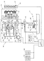
以下、図面を参照して本発明の好ましい実施の形態について詳細に説明する。図1は、自動二輪車等の車両に適用される自動変速機としての自動マニュアル変速機(以下、AMT)およびその周辺装置のシステム構成図である。また、図2は、AMT16における各軸および変速ギヤの噛合関係を示す配置関係図である。AMT16は、主軸(メインシャフト)上に配設されたクラッチCLによってエンジンの回転駆動力を断接するシングルクラッチ式変速装置である。エンジン11に連結されるAMT16は、クラッチ用油圧装置17および変速制御装置としてのAMT制御ユニット18によって駆動制御される。エンジン11は、スロットル・バイ・ワイヤ形式のスロットルボディ19を有し、スロットルボディ19にはスロットル開閉用のモータ20が備えられている。
Hereinafter, preferred embodiments of the present invention will be described in detail with reference to the drawings. FIG. 1 is a system configuration diagram of an automatic manual transmission (hereinafter referred to as AMT) as an automatic transmission applied to a vehicle such as a motorcycle and its peripheral devices. FIG. 2 is an arrangement relationship diagram showing the meshing relationship between the shafts and the transmission gears in the
AMT16は、前進6段の変速機21、クラッチCL、シフトドラム24、およびシフトドラム24を回動させるシフト制御モータ25を備えている。変速機21を構成する多数のギヤは、主軸(メインシャフト)26およびカウンタ軸(カウンタシャフト)27にそれぞれ結合または遊嵌されている。主軸26およびカウンタ軸27には、それぞれ主軸26およびカウンタ軸27の軸方向に変位自在な変速ギヤが設けられており、これら変速ギヤおよびシフトドラム24に形成されたガイド溝に、それぞれシフトフォーク29の端部が係合されている。
The AMT 16 includes a six-
エンジン11の出力軸、すなわちクランク軸30には、プライマリ駆動ギヤ31が結合されており、このプライマリ駆動ギヤ31はプライマリ従動ギヤ32に噛み合わされている。プライマリ従動ギヤ32は、クラッチCLを介して主軸26に連結されている。また、AMT16は、カウンタ軸27上の所定の変速ギヤの回転速度を計測することで、主軸26の回転速度を検出する主軸回転速度センサ65を備えている。
A
カウンタ軸27には駆動スプロケット35が結合されており、この駆動スプロケット35に巻き掛けられるドライブチェーン(不図示)を介して、駆動輪としての後輪に駆動力が伝達される。また、AMT16内には、プライマリ従動ギヤ32の外周に対向配置されたプライマリ従動ギヤ回転速度センサ36と、シフトドラム24の回転位置に基づいて変速機21のギヤ段位を検出するギヤポジションセンサ38と、シフト制御モータ25によって駆動されるシフタの回動位置を検知するシフタスイッチ64と、シフトドラム24がニュートラル位置にあることを検知するニュートラルスイッチ63とが設けられている。また、スロットルボディ19には、スロットル開度を検出するスロットル開度センサ47が設けられている。なお、プライマリ従動ギヤ回転速度センサ36の出力信号は、エンジン回転数として検出してもよい。
A driving
クラッチ用油圧装置17は、エンジン11の潤滑油とクラッチCLを駆動する作動油とを兼用する構成を有している。クラッチ用油圧装置17は、オイルタンク39と、このオイルタンク39内のオイル(作動油)をクラッチCLに給送するための管路40とを備えている。管路40上には、油圧供給源としての油圧ポンプ41、アクチュエータとしてのバルブ(電磁制御弁)42が設けられており、管路40に連結される戻り管路43上には、バルブ42に供給する油圧を一定値に保つためのレギュレータ44が配置されている。バルブ42には、オイルの戻り管路45が設けられている。
The clutch
バルブ42とクラッチCLとを連結している管路には、この管路に生じる油圧、すなわち、クラッチCLに生じる油圧を計測する油圧センサ66が設けられている。また、油圧ポンプ41とバルブ42とを連結する管路40には、主油圧センサ77および油温検出手段としての油温センサ78が設けられている。
A
AMT制御ユニット18には、自動変速(AT)モードと手動変速(MT)モードとの切り換えを行うモードスイッチ49と、シフトアップ(UP)またはシフトダウン(DN)の変速指示を行うシフトセレクトスイッチ50とが接続されている。AMT制御ユニット18は、中央演算処理装置(CPU)を備え、上記した各センサやスイッチの出力信号に応じてバルブ42およびシフト制御モータ25を制御し、AMT16の変速段位を自動的または半自動的に切り換えることができる。
The
AMT制御ユニット18は、ATモードの選択時には、車速、エンジン回転数、スロットル開度等の情報に応じて変速段位を自動的に切り換え、一方、MTモードの選択時には、シフトセレクトスイッチ50の操作に伴って、変速機21をシフトアップまたはシフトダウンさせる。なお、MTモード選択時でも、エンジンの過回転やストールを防止するための補助的な自動変速制御を実行することが可能である。
When the AT mode is selected, the
クラッチ用油圧装置17においては、油圧ポンプ41によってバルブ42に油圧がかけられており、この油圧が上限値を超えないようにレギュレータ44で制御されている。AMT制御ユニット18からの指示でバルブ42が開かれると、クラッチCLに油圧が印加されて、プライマリ従動ギヤ32が、クラッチCLを介して主軸26と連結される。一方、バルブ42が閉じられて油圧の印加が停止されると、クラッチCLは、内蔵されている戻りバネ(不図示)によって、主軸26との連結を断つ方向へ付勢される。
In the clutch
管路40とクラッチCLとを連結する管路を開閉することでクラッチを駆動するバルブ42は、AMT制御ユニット18が駆動信号に基づいて、管路の全閉状態から全開状態に至るまでの時間等を任意に変更できるように構成されている。
The
シフト制御モータ25は、AMT制御ユニット18からの指示に従ってシフトドラム24を回動させる。シフトドラム24が回動すると、シフトドラム24の外周に形成されたガイド溝の形状に従ってシフトフォーク29がシフトドラム24の軸方向に変位する。これに伴い、カウンタ軸27および主軸26上のギヤの噛み合わせが変わり、変速機のシフトアップまたはシフトダウンを実行する。
The
図2を併せて参照して、クラッチCLに接続される主軸26は、変速ギヤ対の駆動側ギヤM1〜M6を支持している。第1速駆動ギヤM1は、軸方向に摺動不能かつ周方向に回転可能に取り付けられ、第2速駆動ギヤM2は、主軸26に一体的に形成されている。また、第3速駆動ギヤM3およびこれと一体の第4速駆動ギヤは、軸方向に摺動可能かつ周方向に回転不能に取り付けられている。第5速駆動ギヤM5および第6速駆動ギヤM6は、軸方向に摺動不能かつ周方向に回転可能に取り付けられている。
Referring also to FIG. 2, the
また、カウンタ軸27は、駆動ギヤM1〜M6に噛合する被動ギヤC1〜C6を支持している。第1速から4速の被動ギヤC1〜C4は、軸方向に摺動不能かつ周方向に回転可能に取り付けられており、第5,6速の被動ギヤC5,C6は、軸方向に摺動可能かつ周方向に回転不能に取り付けられている。AMT16は、上記した歯車列のうち、駆動ギヤM3,M4および被動ギヤC5,C6、すなわち、軸方向に摺動可能なギヤをシフトフォーク29で摺動させることで、ドグクラッチを断接して変速動作を実行することができる。
The
本実施形態に係るAMT16は、主軸26に任意のブレーキ力(制動力)を与えることができるブレーキ手段としての主軸ブレーキ60を具備している。主軸ブレーキ60は、AMT制御ユニット18からの駆動指令で作動する摩擦式ブレーキであり、主軸26の端部に固定された円盤状の被制動部材61と、被制動部材61に当接する制動部材62とから構成されている。なお、ブレーキ手段60は、電磁式ブレーキ等で構成してもよい。
The
図3は、AMT制御ユニット18およびその周辺機器の構成を示すブロック図である。前記と同一符号は同一または同等部分を示す。AMT制御ユニット18は、変速マップ101が格納された変速制御部100を備える。クラッチ制御手段を含む変速制御部100は、車両の通常走行時、ギヤポジションセンサ38、エンジン回転数センサ90、スロットル開度センサ47、車速センサ91および車速情報に基づき、3次元マップ等からなる変速マップ101に従って、シフト制御モータ25およびバルブ42を駆動して変速動作を実行する。なお、エンジン回転数は、プライマリ従動ギヤ回転速度センサ36の出力信号に基づいて検知してもよい。
FIG. 3 is a block diagram showing the configuration of the
本実施形態に係るAMT制御ユニット18は、クラッチCLに対する入力側および出力側の回転速度を検出することにより、クラッチCLを接続する際のつながり始めタイミングを検出することができる。本実施形態では、クラッチCLに対する入力側の回転速度を、入力側回転体としてのプライマリ従動ギヤ32の回転速度を検出するプライマリ従動ギヤ回転速度センサ36で検出し、また、出力側の回転速度を、出力側回転体としての主軸26の回転速度を検出する主軸回転速度センサ65で検出し、両者が同期回転するタイミングを検出するように構成されている。具体的には、プライマリ従動ギヤ32の回転速度と主軸26の回転速度との差が所定値(例えば、50rpm)以下になると、クラッチCLがつながり始めたと判定する。
The
クラッチつながり始め検出手段120は、主軸回転速度センサ65およびプライマリ従動ギヤ回転速度センサ36の出力情報に基づいて、クラッチCLがつながり始めたことを検出する。なお、このつながり始めの検出は、クラッチCLを切断した状態から接続方向に駆動していった際に、主軸26とプライマリ従動ギヤ32とが同期回転する点を検出することで実行されるので、AMT16をシングルクラッチ式とする本実施形態では、変速機21がニュートラル位置にある時に行うように設定されている。
The clutch engagement start detection means 120 detects that the clutch CL has started to be engaged based on the output information of the main shaft
そして、クラッチつながり始め検出手段120は、クラッチCLのつながり始めの検出時に、主軸ブレーキ60を駆動制御して主軸26を一旦停止させる。これは、主軸26が、潤滑油の粘性や各種のフリクションによって、クラッチCLが切断された状態でもクラッチ側と連れ回りしようとするためである。これにより、主軸ブレーキ60で主軸26を一旦停止させて、つながり始めの検出に適した状態とした後に、クラッチCLを接続方向に駆動するように設定されている。
Then, the clutch engagement start detection means 120 drives and controls the
なお、クラッチを接続方向に駆動する際の主軸ブレーキ60は、完全な開放状態とするほか、潤滑油の粘性等による連れ回りを防ぐために所定の制動力を与えたままの状態とすることができる。この時の制動力の大きさは、フリクションの大きさ等に合わせて任意に設定することができる。また、クラッチCLを接続方向に駆動する速度も任意に設定可能である。
Note that the
クラッチ制御量検出手段150は、クラッチ油圧センサ66の出力情報に基づいてクラッチCLの制御量(油圧)を検出する。そして、クラッチつながり始め制御量検出手段110は、クラッチつながり始め検出手段120およびクラッチ制御量検出手段150の出力信号に基づいて、つながり始め時のクラッチCLの制御量を検出する。
The clutch control amount detection means 150 detects the control amount (hydraulic pressure) of the clutch CL based on the output information of the clutch
クラッチ補正制御量導出手段130は、クラッチつながり始め検出手段120と、クラッチ制御量検出手段150からの出力信号に基づいて、クラッチCLがつながり始めた時の制御量(油圧)を検出し、この制御量をクラッチ制御補正量データテーブル140に適用することで制御補正量を導出する。クラッチ制御補正量データテーブル140は、図5に示すように、油圧Pに対する制御補正量Hが一義的に定まるように構成されたものである。そして、クラッチ補正制御量導出手段130は、導出された補正制御量Hを変速制御部100に伝達する。変速制御部100は、伝達された制御補正量Hに基づいて、クラッチCLをフィードバック制御する。
The clutch correction control
なお、クラッチつながり始め制御量検出手段110は、主軸26とプライマリ従動ギヤ32とが同期回転するまでのクラッチの制御量が所定制御量を超えた場合には、警告灯やスピーカ等からなる警告手段92を用いて、クラッチがつながり始めるまでの制御量が大きくなったことを乗員に知らせるように構成されている。これにより、これにより、摩耗したクラッチ板を交換する等の対処を乗員に促すことができる。
The clutch engagement start control amount detection means 110 is a warning means comprising a warning light, a speaker or the like when the control amount of the clutch until the
図4は、本実施形態に係るクラッチつながり始め検知制御の流れを示すフローチャートである。この一連の制御は、車両の停車中に実行される。ステップS1では、主軸回転速度センサ65の出力信号が検出され、ステップS2では、プライマリ従動ギヤ回転速度センサ36の出力信号が検出される。ステップS3では、クラッチ油圧センサ66の出力信号が検出される。続くステップS4では、シフトドラム24がニュートラル位置にあるか否かが検出される。ステップS4で肯定判定されると、ステップS5へ進み、主軸ブレーキ60を駆動することで主軸26の回転を一旦停止させる。これにより、クラッチのつながり始めを検出する準備が整うこととなる。なお、ステップS4で否定判定されるとステップS1に戻る。
FIG. 4 is a flowchart showing a flow of clutch engagement start detection control according to the present embodiment. This series of control is executed while the vehicle is stopped. In step S1, the output signal of the spindle
続くステップS6では、主軸ブレーキ60を所定圧で所定時間の間駆動して、ブレーキ動作を保持する。なお、ブレーキ動作を保持する所定時間やブレーキ力の大きさは、主軸26が連れ回りさせようとするフリクションに応じて任意に設定することができる。次に、ステップS7では、主軸ブレーキ60を解除し、ステップS8においてクラッチCLを接続方向に駆動する。そして、ステップS9では、主軸回転速度センサ65によって検出される主軸26の回転速度と、プライマリ従動ギヤ回転速度センサ36によって検出されるプライマリ従動ギヤ32の回転速度とが同期したか否かが判定される。本実施形態では、回転速度差が所定値(例えば、1m/s)以下になることで、両者の回転速度が同期したと判定するように設定されている。この設定によれば、各回転速度センサの精度ばらつき等を考慮して、回転速度の同期状態を検出することができる。
In the subsequent step S6, the
そして、ステップS9で肯定判定されると、ステップS10では、同期回転した時点においてクラッチ油圧センサ66で検出された油圧値を、クラッチの制御量として記憶する。なお、ステップS9で否定判定されるとステップS7に戻る。
If the determination in step S9 is affirmative, in step S10, the hydraulic pressure value detected by the clutch
ステップS11では、油圧−クラッチ制御補正量データテーブル140に基づいて制御補正量Hを導出する。そして、ステップS12では、制御補正量Hに基づいてクラッチCLをフィードバック制御し、一連の制御を終了する。 In step S11, a control correction amount H is derived based on the hydraulic pressure-clutch control correction amount data table 140. In step S12, the clutch CL is feedback-controlled based on the control correction amount H, and the series of controls is terminated.
なお、上記したフローチャートでは、常に油圧−クラッチ制御補正量データテーブル140を用いてクラッチを制御しているが、このようなフィードバック制御は、つながり始め時に検出された制御量と予め設定された基準制御量とを比較し、両者の差異が所定値より大きい場合にのみ実行するようにしてもよい。また、クラッチのつながり始めの検知は、エンジンが始動されてから発車するまでの間や、AMTに記憶された所定周期で定期的に実行することができる。この所定周期は、油温等の各種情報に基づいて随時変更することができる。また、本実施形態では、クラッチCLに生じている油圧に基づいて制御補正量を検出しているが、クラッチCLへの作動油の供給量を制御しているアクチュエータとしてのバルブ42の駆動電流値に基づいて検出してもよい。
In the above-described flowchart, the clutch is always controlled using the hydraulic pressure-clutch control correction amount data table 140. However, such feedback control is performed using a control amount detected at the start of connection and a preset reference control. It may be executed only when the amount is compared and the difference between the two is larger than a predetermined value. Further, the detection of the start of clutch engagement can be periodically executed from when the engine is started until the vehicle is started, or at regular intervals stored in the AMT. This predetermined period can be changed at any time based on various information such as the oil temperature. In the present embodiment, the control correction amount is detected based on the hydraulic pressure generated in the clutch CL, but the drive current value of the
上記したように、本実施形態に係るクラッチ制御装置によれば、クラッチを切断した状態で出力側回転体と入力側回転体とが連れ回りしようとする場合でも、ブレーキ手段で出力側回転体を一時停止させることで、両者の回転速度差が所定値以下になるタイミングを正確に検知することが可能となる。これにより、クラッチのつながり始め状態を正確に検出して、適切なフィードバック制御を実行することが可能となる。 As described above, according to the clutch control device according to the present embodiment, even when the output-side rotator and the input-side rotator try to rotate with the clutch disengaged, the brake means causes the output-side rotator to rotate. By temporarily stopping, it becomes possible to accurately detect the timing at which the difference in rotational speed between the two becomes a predetermined value or less. As a result, it is possible to accurately detect the clutch engagement start state and execute appropriate feedback control.
なお、本実施形態に係るAMT16は、主軸26に制動力を与える主軸ブレーキ60を備えているため、車両の停車中、すなわちカウンタ軸27の停止中に主軸ブレーキ60を作動させて主軸26とカウンタ軸27との回転速度差を小さくしておくと、ニュートラルから1速に変速する際のドグクラッチの噛み合い音を低減できる。
Since the
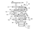
図6は、本発明の第2実施形態に係るAMT16aおよびその周辺装置のシステム構成図である。前記と同一符号は同一または同等部分を示す。また、図7は、AMT16aにおける各軸および変速ギヤの噛合関係を示す配置関係図である。AMT16aは、主軸上に配設された2つのクラッチによってエンジンの回転駆動力を断接するツインクラッチ式変速装置として構成されている。ツインクラッチおよびツインクラッチの駆動制御部を除く全体構成は、前記した実施形態と同様のため詳細は省略する。
FIG. 6 is a system configuration diagram of the
AMT16aは、前進6段の変速機21、第1クラッチCL1、第2クラッチCL2、シフトドラム24、およびシフトドラム24を回動させるシフト制御モータ25を備えている。変速機21を構成する多数のギヤは、主軸26およびカウンタ軸27にそれぞれ結合または遊嵌されている。主軸26は、互い回転自在に軸支された内主軸26aと外主軸26bとからなる。内主軸26aは第1クラッチCL1と結合され、外主軸26bは第2クラッチCL2と結合されている。主軸26およびカウンタ軸27には、それぞれ主軸26およびカウンタ軸27の軸方向に変位自在な変速ギヤが設けられており、これら変速ギヤおよびシフトドラム24に形成されたガイド溝に、それぞれシフトフォーク23の端部が係合されている。
The
エンジン11の出力軸、すなわちクランク軸30には、プライマリ駆動ギヤ31が結合されており、このプライマリ駆動ギヤ31はプライマリ従動ギヤ32に噛み合わされている。プライマリ従動ギヤ32は、第1クラッチCL1を介して内主軸26aに連結されると共に、第2クラッチCL2を介して外主軸26bに連結されている。また、AMT16aは、カウンタ軸27上の所定の変速ギヤの回転速度を計測することで、内主軸26aおよび外主軸26bの回転速度をそれぞれ検出する内主軸回転速度センサ73および外主軸回転速度センサ74を備えている。
A
アクチュエータとしてのバルブは、第1クラッチCL1および第2クラッチCL2に個別に油圧をかけることができる第1バルブ42aおよび第2バルブ42bとからなり、それぞれにオイルの戻り管路45が設けられている。
The valve as an actuator includes a
第1バルブ42aと第1クラッチCL1とを連結している管路には、第1クラッチCL1に生じる油圧を計測する第1クラッチ油圧センサ75が設けられている。同様に、第2バルブ42bと第2クラッチCL2とを連結している管路には、第2クラッチCL2に生じる油圧を計測する第2クラッチ油圧センサ76が設けられている。
A pipe line connecting the
クラッチ用油圧装置17においては、油圧ポンプ41によってバルブ42に油圧がかけられており、この油圧が上限値を超えないようにレギュレータ44で制御されている。AMT制御ユニット18からの指示でバルブ42aまたは42bが開かれると、第1クラッチCL1または第2クラッチCL2に油圧が印加されて、プライマリ従動ギヤ32が、第1クラッチCL1または第2クラッチCL2を介して内主軸26aまたは外主軸26bと連結される。一方、バルブが閉じられて油圧の印加が停止されると、第1クラッチCL1および第2クラッチCL2は、内蔵されている戻りバネによって、内主軸26aおよび外主軸26bとの連結を断つ方向へ付勢されることとなる。
In the clutch
シフト制御モータ25は、AMT制御ユニット18からの指示に従ってシフトドラム24を回動させる。シフトドラム24が回動すると、シフトドラム24の外周に形成されたガイド溝の形状に従ってシフトフォーク23がシフトドラム24の軸方向に変位する。これに伴い、カウンタ軸27および主軸26上のギヤの噛み合わせが変わり、変速機のシフトアップまたはシフトダウンを実行する。
The
本実施形態に係るAMT16aでは、第1クラッチCL1と結合される内主軸26aが奇数段ギヤ(1,3,5速)を支持し、第2クラッチCL2と結合される外主軸26bが偶数段ギヤ(2,4,6速)を支持するように構成されている。したがって、例えば、奇数段ギヤで走行している間は、第1クラッチCL1への油圧供給が継続されて接続状態が保たれている。そして、シフトチェンジが行われる際には、シフトドラム24の回動によってギヤの噛み合わせを予め変更しておくことにより、両クラッチの接続状態を切り換えるのみで変速動作を完了することが可能となる。
In the
図7を併せて参照して、第1クラッチCL1に接続される内主軸26aは、奇数変速段の駆動ギヤM1,M3,M5を支持している。第1速駆動ギヤM1は、内主軸26aに一体的に形成されている。また、第3速駆動ギヤM3は、軸方向に摺動可能かつ周方向に回転不能に取り付けられており、第5速駆動ギヤM5は、軸方向に摺動不能かつ周方向に回転可能に取り付けられている。一方、第2クラッチCL2に接続される外主軸26bは、偶数変速段の駆動ギヤM2,M4,M6を支持している。第2速駆動ギヤM2は、外主軸26bに一体的に形成されている。また、第4速駆動ギヤM4は、軸方向に摺動可能かつ周方向に回転不能に取り付けられており、第6速駆動ギヤM6は、軸方向に摺動不能かつ周方向に回転可能に取り付けられている。
Referring also to FIG. 7, the inner
また、カウンタ軸27は、駆動ギヤM1〜M6に噛合する被動ギヤC1〜C6を支持している。第1速から4速の被動ギヤC1〜C4は、軸方向に摺動不能かつ周方向に回転可能に取り付けられており、第5,6速の被動ギヤC5,C6は、軸方向に摺動可能かつ周方向に回転不能に取り付けられている。AMT16aでは、上記歯車列のうち、駆動ギヤM3,M4および被動ギヤC5,C6、すなわち、軸方向に摺動可能なギヤをシフトフォーク23で摺動させることで、ドグクラッチを断接して変速動作を行う。
The
そして、本実施形態に係るAMT16aは、内主軸26aおよび外主軸26bのそれぞれに内主軸ブレーキ70および外主軸ブレーキ80を具備している。内主軸26aに制動力を与える内主軸ブレーキ70は、内主軸26aに固定された円盤状の被制動部材71と、被制動部材71に当接する制動部材72とから構成されている。また、外主軸26bに制動力を与える外主軸ブレーキ80は、外主軸26bに固定された円盤状の被制動部材81と、被制動部材81に当接する制動部材82とから構成されている。
The
本実施形態に係るAMT16aは、例えば、第1速ギヤの選択時には、クランク軸30からプライマリ従動ギヤ32に伝達されたエンジンの回転駆動力を、第1クラッチCL1が接続されることで内主軸26aに伝達し、第1速駆動ギヤM1から第1速被動側C1を介してカウンタ軸27に伝達している。このとき、第1速用のドグクラッチは、第1速被動ギヤC1と第5速被動ギヤC5との間で噛み合った状態にある。
In the
そして、AMT16aは、第1速ギヤによって回転駆動力が伝達されている際に、第2速用のドグクラッチ、すなわち、第6速被動ギヤC6と第2速被動ギヤC2との間のドグクラッチを噛合させて第2速への変速に備える「予備変速」の実行が可能である。このとき、第2クラッチCL2は遮断されているので、第1速ギヤでの走行中に第2速用のドグクラッチが噛合されても、エンジンの回転駆動力は、第2速駆動ギヤM2を介して外主軸26bを空転させるのみである。そして、この予備変速後に、クラッチの接続状態を、第1クラッチCL1から第2クラッチCL2に持ち替えると、回転駆動力が途切れることなく、瞬時に2速ギヤを介してカウンタ軸から出力することができる。
The
また、AMT16aのシフトドラム24は、各変速段を選択するための各所定回動位置同士の間に、偶数段ギヤのグループまたは奇数段ギヤのグループのうち、回転駆動力を伝達していない側のグループをニュートラル状態とする「ニュートラル待ち」の位置が設定されている。このため、偶数段ギヤでの走行中に奇数段ギヤをニュートラル状態にすると共に、奇数段ギヤでの走行中に偶数段ギヤをニュートラル状態とすることが可能である。したがって、本実施形態に係るAMT16aの構成によれば、車両の停車中のみならず、所定ギヤを選択して走行している間においても、両クラッチCL1,CL2に対してクラッチのつながり始め検出を実行することができる。
Further, the
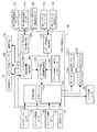
図8は、本発明の第2実施形態に係るAMT制御ユニット18およびその周辺機器の構成を示すブロック図である。前記と同一符号は同一または同等部分を示す。本実施形態においては、第1クラッチCL1および第2クラッチCL2を駆動するバルブが第1バルブ42aおよび第2バルブ42bから構成されること、内主軸回転速度センサ73および外主軸回転速度センサ74を備えること、内主軸26aを制動する内主軸ブレーキ70および外主軸26bを制動する外主軸ブレーキ80を備えることを除いては、前記した実施形態と同様であるので、詳細な説明は省略する。
FIG. 8 is a block diagram showing the configuration of the
AMT制御ユニット18は、両クラッチCL1,CL2に対する入力側回転数と出力側回転数とを検出することで、両クラッチCL1,CL2を接続する際のつながり始めタイミングをそれぞれ検出することができる。本実施形態では、第1クラッチCL1に対する出力側の回転速度を内主軸回転速度センサ73で検出し、一方、第2クラッチCL2に対する出力側の回転速度を外主軸回転速度センサ74で検出する。なお、入力側の回転速度は、いずれもプライマリ従動ギヤ回転速度センサ36によって検出する。
The
前記したように、クラッチのつながり始めの検出は、第1クラッチCL1または第2クラッチCL2を切断した状態から徐々に接続方向に駆動していった際に、内主軸26aまたは外主軸26bと、プライマリ従動ギヤ32とが同期回転するタイミングを検出することで実行される。ツインクラッチ式のAMT16aでは、所定変速段で走行中、シフトドラムが所定の「ニュートラル待ち」位置にある場合に、第1クラッチCL1または第2クラッチCL2のうち、切断されている側に対してつながり始めの検出を実行できる。すなわち、偶数段ギヤで走行中には第1クラッチCL1に対してつながり始めの検出が可能であり、奇数段ギヤで走行中には第2クラッチCL2に対してつながり始めの検出が可能である。なお、変速機21がニュートラル状態にある停車中においては、第1クラッチCL1および第2クラッチCL2に対して交互に検出可能である。
As described above, the start of clutch engagement is detected when the first main clutch CL1 or the second main clutch CL2 is gradually driven from the disengaged state in the connected direction, and the inner
クラッチつながり始め検出手段120は、第1クラッチCL1のつながり始めの検出時に内主軸ブレーキ70を駆動制御し、第2クラッチCL2のつながり始めの検出時に外主軸ブレーキ80を駆動制御する。なお、クラッチのつながり始めを検出する際において、内主軸ブレーキ70または外主軸ブレーキ80は、完全な開放状態とするほか、クラッチの潤滑油の粘性や、内主軸26aと外主軸26bとの間に生じるフリクション等による連れ回りを防ぐために、所定の制動力を与えたままとすることができる。この制動力の大きさは、フリクション等の大きさに応じて任意に設定することができる。
The clutch connection start detecting
クラッチ制御量検出手段150は、第1クラッチ油圧センサ75および第2クラッチ油圧センサ76の出力情報に基づいて、第1クラッチCL1および第2クラッチCL2の制御量を検出する。そして、クラッチつながり始め制御量検出手段110は、クラッチつながり始め検出手段120およびクラッチ制御量検出手段150の出力信号に基づいて、両クラッチがつながり始めた時の制御量をそれぞれ検出する。
The clutch control amount detection means 150 detects the control amounts of the first clutch CL1 and the second clutch CL2 based on the output information of the first clutch
クラッチ補正制御量導出手段130は、クラッチつながり始め検出手段120と、クラッチ制御量検出手段150からの出力信号に基づいて、両クラッチがつながり始めた時の制御量(油圧)を検出し、この制御量をクラッチ制御補正量データテーブル140に適用することで制御補正量を導出する。
The clutch correction control
図9は、本発明の第2実施形態に係るクラッチつながり始め検知制御の流れを示すフローチャートである。なお、クラッチのつながり始めの検出時に、主軸を一旦停止させてからクラッチを接続方向に駆動して回転速度の同期タイミングを検出し、つながり始めが検出された時の制御量に基づいて制御補正量を導出するまでの流れは、図4で説明したシングルクラッチ式の場合と同様なので、ここでは、ツインクラッチ式のAMT16aにおいて、第1クラッチCL1および第2クラッチCL2に対して、どのような順序でつながり始めの検出を実行するかを主に説明する。
FIG. 9 is a flowchart showing a flow of clutch engagement start detection control according to the second embodiment of the present invention. When detecting the start of clutch engagement, the main shaft is temporarily stopped and then the clutch is driven in the connecting direction to detect the rotational speed synchronization timing. Based on the control amount when the start of engagement is detected, the control correction amount 4 is the same as that in the case of the single clutch type described with reference to FIG. 4. Here, in the twin
まず、ステップS20〜24では、内主軸回転速度センサ73、外主軸回転速度センサ74、プライマリ従動ギヤ回転速度センサ36、第1クラッチ油圧センサ75、第2クラッチ油圧センサ76の出力信号がそれぞれ検出される。
First, in steps S20 to S24, output signals of the inner main shaft
続くステップS25では、シフトドラム24がニュートラル位置にあるか否かが検出される。なお、ここでのニュートラル位置とは、偶数段ギヤおよび奇数段ギヤが共にニュートラル状態となり、前記したニュートラルスイッチ63がオンとなる回動位置を指す。このニュートラル位置は、AMT16aが自動変速(AT)モードにある場合は、車両の停車中にのみ選択されるように設定されている。すなわち、ステップS25で肯定判定された場合は、車両が停車中であるとして、ステップS26に進む。
In the subsequent step S25, it is detected whether or not the
ステップS26では、内主軸ブレーキ70を駆動して第1クラッチCL1の制御補正量を導出し、続くステップS27では、外主軸ブレーキ80を駆動して第2クラッチCL2の制御補正量を導出して、ステップS33に進んで両クラッチをフィードバック制御して一連の制御を終了する。なお、ステップS25で肯定判定された場合のつながり始め検出は、第2クラッチCL2から開始してもよい。
In step S26, the inner
一方、ステップS25で否定判定された場合は、車両が走行中であるとしてステップS28に進み、変速ギヤが偶数段であるか否かが判定される。ステップS28で肯定判定されるとステップS29に進んで、外主軸ブレーキ80を駆動してつながり始めを検出し、第2クラッチCL2の制御補正量を導出する。
On the other hand, if a negative determination is made in step S25, it is determined that the vehicle is traveling, the process proceeds to step S28, and it is determined whether or not the transmission gear is in an even-numbered stage. If an affirmative determination is made in step S28, the process proceeds to step S29, where the
続くステップS31では、1段変速されたか否かが判定され、肯定判定されると、偶数段ギヤに移行したものとして、ステップS32に進む。ステップS32では、内主軸ブレーキ70を駆動して第1クラッチCL1の制御補正量を導出する。これにより、両クラッチCL1,CL2の制御補正量が導出され、ステップS33に進んでフィードバック制御を実行し、一連の制御を終了する。なお、ステップS31で否定判定されると、ステップS33に進んでフィードバック制御を実行する。第1クラッチCL1の制御補正量は、次に検出準備が整った時に導出される。また、制御補正量を適用したクラッチ制御は、いずれか一方の制御補正量が導出された時点で直ちに実行してもよい。
In a succeeding step S31, it is determined whether or not the first speed has been changed. If an affirmative determination is made, it is determined that the gear has shifted to an even gear and the process proceeds to a step S32. In step S32, the
また、ステップS28で否定判定される、すなわち、変速段が偶数段であると判定された場合は、ステップS30に進み、内主軸ブレーキ70を駆動して第1クラッチCL1の制御補正量を導出する。そして、ステップS34では、1段変速されたか否かが判定され、肯定判定されると、奇数段ギヤに変速されたものとして、ステップS35に進む。ステップS35では、外主軸ブレーキ80を駆動して第2クラッチCL2の制御補正量を導出する。これにより、両クラッチCL1,CL2の制御補正量が導出され、ステップS33に進んでフィードバック制御を実行し、一連の制御を終了する。なお、ステップS34で否定判定されるとステップS33に進む。第2クラッチCL2の制御補正量は、次につながり始めの検出準備が整った時に導出される。なお、本実施形態でも、内主軸ブレーキ70および外主軸ブレーキ80を駆動する所定時間やブレーキ力の大きさは、フリクション等に応じて任意に設定することができる。
Further, when a negative determination is made in step S28, that is, when it is determined that the shift speed is an even speed, the process proceeds to step S30 to drive the
上記したように、本発明の第2実施形態に係るクラッチ制御装置では、クラッチのつながり始めの検出を、第1クラッチCL1および第2クラッチCL2に対して交互に実行することにより、車両の走行中においても両クラッチのつながり始め状態を検知して、走行中にクラッチのつながり始め状態が変化した場合でも、クラッチ制御の補正量を随時更新してクラッチの制御にフィードバックすることが可能となる。 As described above, in the clutch control device according to the second embodiment of the present invention, by detecting the start of clutch engagement alternately for the first clutch CL1 and the second clutch CL2, the vehicle is running. In this case, it is possible to detect the connection start state of both clutches and update the clutch control correction amount at any time and feed back to the clutch control even when the clutch connection start state changes during traveling.
上記したように、本実施形態に係るクラッチ制御装置によれば、クラッチを切断した状態で出力側回転体と入力側回転体とが連れ回りしようとする場合でも、ブレーキ手段で出力側回転体を一時停止させることで、出力側回転体と入力側回転体との回転速度差が所定値以下になるタイミングを正確に検知することが可能となる。これにより、クラッチのつながり始め状態を正確に検出して、適切なフィードバック制御を実行することができるようになる。 As described above, according to the clutch control device according to the present embodiment, even when the output-side rotator and the input-side rotator try to rotate with the clutch disengaged, the brake means causes the output-side rotator to rotate. By temporarily stopping, it becomes possible to accurately detect the timing at which the rotational speed difference between the output-side rotator and the input-side rotator becomes a predetermined value or less. Thereby, it is possible to accurately detect the clutch engagement start state and execute appropriate feedback control.
なお、ツインクラッチ式変速装置、ブレーキ手段、クラッチの入力側回転体および出力側回転体の回転速度検出手段の構成、クラッチ制御量−補正量データテーブルの構成、入力側回転体および出力側回転体が同期回転したことを判定する所定値の設定、出力側回転体を一旦停止させた後の制動力の設定等は、上記した実施形態に限られず、種々の変更が可能である。本発明に係るクラッチ制御装置は、自動二輪車に限られず、三輪車や四輪車等に適用してもよい。 It should be noted that the twin clutch transmission, the brake means, the configuration of the rotational speed detection means of the input side rotating body and the output side rotating body of the clutch, the configuration of the clutch control amount-correction amount data table, the input side rotating body and the output side rotating body The setting of a predetermined value for determining that the motor has rotated synchronously, the setting of the braking force after the output-side rotating body has been temporarily stopped, and the like are not limited to the above-described embodiments, and various changes can be made. The clutch control device according to the present invention is not limited to a motorcycle, and may be applied to a tricycle, a four-wheel vehicle, or the like.
11…エンジン(動力源)、16,16a…AMT、25…シフト制御モータ、36…プライマリ従動ギヤ回転速度センサ(入力側回転速度検出手段)、42…バルブ、42a…第1バルブ、42b…第2バルブ、26…主軸、26a…内主軸、26b…外主軸、27…カウンタ軸、65…主軸回転速度センサ(出力側回転速度検出手段)、73…内主軸回転速度センサ(出力側回転速度検出手段)、74…外主軸回転速度センサ(出力側回転速度検出手段)、75…第1クラッチ油圧センサ、76…第2クラッチ油圧センサ、100…変速制御部(クラッチ制御手段)、120…つながり始め検出手段、110…つながり始め制御量検出手段、130…クラッチ補正制御量導出手段、140…油圧−クラッチ制御補正量データテーブル、150…クラッチ制御量検出手段、CL…クラッチ、CL1…第1クラッチ、CL2…第2クラッチ、M1〜6…第1〜6速駆動ギヤ、C1〜6…第1〜6速被動ギヤ
DESCRIPTION OF
Claims (7)
前記クラッチ(CL)は、該クラッチ(CL)が接続された状態で同期回転する入力側回転体および出力側回転体を有し、
前記入力側回転体の回転速度を検出する入力側回転速度検出手段(36)と、
前記出力側回転体の回転速度を検出する出力側回転速度検出手段(65,73,74)と、
前記クラッチ(CL)のクラッチ制御量を制御するクラッチ制御手段(100)と、
前記クラッチ(CL)の切断中に前記出力側回転体を一旦停止させるブレーキ手段(60)と、
前記クラッチ制御量を検出するクラッチ制御量検出手段(150)と、
前記入力側回転体と出力側回転体との回転速度差が所定値以下となった場合に前記クラッチ(CL)のつながり始めを検出するつながり始め検出手段(120)と、
前記つながり始めにおける前記クラッチ制御量を検出するつながり始め制御量検出手段(110)と、
前記出力側回転体を一旦停止させた後に前記つながり始めが検出された時点での前記クラッチ制御量に基づいて、前記クラッチ(CL)の補正制御量を導出するクラッチ補正制御量導出手段(130)とを具備し、
前記クラッチ制御手段(100)に対し、前記補正制御量に基づいて前記クラッチ制御量をフィードバック制御し、
前記回転駆動力を所定の変速比で前記駆動輪に伝達する有段変速機(21)を備え、
前記クラッチ(CL)は、第1クラッチ(CL1)および第2クラッチ(CL2)からなるツインクラッチであると共に、前記有段変速機(21)の変速動作毎に前記ツインクラッチの断接状態を交互に切り換えるように構成されており、
前記有段変速機(21)は、奇数段ギヤまたは偶数段ギヤのうち、前記第1クラッチ(CL1)または第2クラッチ(CL2)が切断されることで前記回転駆動力を伝達していない側のギヤをニュートラル状態にすることができるように構成されており、
前記つながり始め検出手段(120)は、前記第1クラッチ(CL1)または第2クラッチ(CL2)のうちの切断されている側に対して、前記つながり始めの検出を行うことを特徴とするクラッチ制御装置。 In the clutch control device for the clutch (CL) for connecting and disconnecting the rotational driving force transmitted from the power source (11) of the vehicle to the driving wheels,
The clutch (CL) has an input side rotating body and an output side rotating body that rotate synchronously with the clutch (CL) connected,
Input side rotational speed detection means (36) for detecting the rotational speed of the input side rotational body;
Output-side rotational speed detecting means (65, 73, 74) for detecting the rotational speed of the output-side rotating body;
Clutch control means (100) for controlling the clutch control amount of the clutch (CL) ;
Brake means (60) for temporarily stopping the output-side rotating body during disengagement of the clutch (CL) ;
Clutch control amount detection means (150) for detecting the clutch control amount;
Connection start detecting means (120) for detecting the start of connection of the clutch (CL) when a difference in rotational speed between the input side rotating body and the output side rotating body is a predetermined value or less;
A connection start control amount detecting means (110) for detecting the clutch control amount at the start of the connection;
Clutch correction control amount deriving means (130) for deriving a correction control amount of the clutch (CL) based on the clutch control amount at the time when the start of connection is detected after the output side rotating body is temporarily stopped. And
Feedback control of the clutch control amount based on the correction control amount to the clutch control means (100) ;
A stepped transmission (21) for transmitting the rotational driving force to the drive wheels at a predetermined gear ratio;
The clutch (CL) is a twin clutch composed of a first clutch (CL1) and a second clutch (CL2), and the connection / disconnection state of the twin clutch is alternately changed for each speed change operation of the stepped transmission (21). Is configured to switch to
The stepped transmission (21) is a side that is not transmitting the rotational driving force by disconnecting the first clutch (CL1) or the second clutch (CL2) of the odd-numbered gear or the even-numbered gear. It is configured to be able to put the gear of the neutral state,
The clutch control characterized in that the connection start detecting means (120) detects the start of connection for the disconnected side of the first clutch (CL1) or the second clutch (CL2). apparatus.
前記つながり始め制御量検出手段(110)は、前記クラッチ(CL)に生じる油圧に基づいて前記クラッチ制御量を導出することを特徴とする請求項1または2に記載のクラッチ制御装置。 The clutch (CL) is hydraulic,
The clutch control device according to claim 1 or 2, wherein the connection start control amount detection means (110) derives the clutch control amount based on a hydraulic pressure generated in the clutch (CL) .
前記油圧供給源(41)とクラッチ(CL)との間に設けられて、前記クラッチ(CL)に供給する作動油の流量を制御するアクチュエータ(42)を備え、
前記つながり始め制御量検出手段(110)は、前記アクチュエータ(42)の駆動電流値に基づいて前記クラッチ制御量を導出することを特徴とする請求項1または2に記載のクラッチ制御装置。 The clutch (CL) is a hydraulic type driven by a hydraulic pressure supplied from a hydraulic pressure supply source (41) ,
An actuator (42) provided between the hydraulic pressure supply source (41) and the clutch (CL) for controlling the flow rate of hydraulic oil supplied to the clutch (CL) ;
The clutch control device according to claim 1 or 2, wherein the connection start control amount detecting means (110) derives the clutch control amount based on a drive current value of the actuator (42) .
Priority Applications (3)
| Application Number | Priority Date | Filing Date | Title |
|---|---|---|---|
| JP2008088032A JP5162767B2 (en) | 2008-03-28 | 2008-03-28 | Clutch control device |
| US12/370,957 US8272994B2 (en) | 2008-03-28 | 2009-02-13 | Clutch control device |
| EP09153083.2A EP2105625B1 (en) | 2008-03-28 | 2009-02-18 | Clutch control device |
Applications Claiming Priority (1)
| Application Number | Priority Date | Filing Date | Title |
|---|---|---|---|
| JP2008088032A JP5162767B2 (en) | 2008-03-28 | 2008-03-28 | Clutch control device |
Publications (3)
| Publication Number | Publication Date |
|---|---|
| JP2009243502A JP2009243502A (en) | 2009-10-22 |
| JP2009243502A5 JP2009243502A5 (en) | 2010-12-24 |
| JP5162767B2 true JP5162767B2 (en) | 2013-03-13 |
Family
ID=40810619
Family Applications (1)
| Application Number | Title | Priority Date | Filing Date |
|---|---|---|---|
| JP2008088032A Active JP5162767B2 (en) | 2008-03-28 | 2008-03-28 | Clutch control device |
Country Status (3)
| Country | Link |
|---|---|
| US (1) | US8272994B2 (en) |
| EP (1) | EP2105625B1 (en) |
| JP (1) | JP5162767B2 (en) |
Families Citing this family (13)
| Publication number | Priority date | Publication date | Assignee | Title |
|---|---|---|---|---|
| JP5374726B2 (en) * | 2008-03-31 | 2013-12-25 | 本田技研工業株式会社 | Clutch control device and μ correction coefficient calculation method |
| JP5620671B2 (en) * | 2009-11-24 | 2014-11-05 | ヤマハ発動機株式会社 | Transmission |
| DE102011014572A1 (en) * | 2010-04-08 | 2011-12-15 | Schaeffler Technologies Gmbh & Co. Kg | Method for controlling an automated clutch |
| DE102010014198A1 (en) * | 2010-04-08 | 2011-10-13 | Schaeffler Technologies Gmbh & Co. Kg | Method for controlling a double clutch |
| JP5501083B2 (en) * | 2010-04-28 | 2014-05-21 | アイシン・エーアイ株式会社 | Vehicle power transmission control device |
| JP5733022B2 (en) * | 2011-05-24 | 2015-06-10 | スズキ株式会社 | Twin clutch automatic transmission control system |
| JP5918946B2 (en) * | 2011-08-29 | 2016-05-18 | アイシン・エーアイ株式会社 | Vehicle power transmission control device |
| JP5929924B2 (en) * | 2012-01-31 | 2016-06-08 | トヨタ自動車株式会社 | Vehicle steering control device |
| JP5931607B2 (en) * | 2012-06-29 | 2016-06-08 | 三菱重工業株式会社 | Centrifugal clutch and refrigeration / air conditioner using the same |
| JP5883755B2 (en) * | 2012-09-28 | 2016-03-15 | 本田技研工業株式会社 | Twin clutch control device |
| JP6137706B2 (en) * | 2015-03-19 | 2017-05-31 | 本田技研工業株式会社 | Vehicle suspension control device |
| US9850965B2 (en) * | 2016-05-03 | 2017-12-26 | Ford Global Technologies, Llc | Method for operating an automatic start/stop system in a vehicle utilizing a fluid launch clutch |
| DE102019205508A1 (en) * | 2019-04-16 | 2020-10-22 | Zf Friedrichshafen Ag | Hybrid transmission device, motor-transmission arrangement, hybrid drive train and motor vehicle |
Family Cites Families (14)
| Publication number | Priority date | Publication date | Assignee | Title |
|---|---|---|---|---|
| US4817776A (en) * | 1985-03-29 | 1989-04-04 | Toshiaki Tateno | Starting control apparatus for automatic transmission system |
| US4899858A (en) * | 1989-03-02 | 1990-02-13 | Eaton Corporation | Method and control system for updating of control parameter value indicative of master clutch point of incipient engagement |
| US5337868A (en) * | 1992-01-02 | 1994-08-16 | Eaton Corporation | Touch point identification for automatic clutch controller |
| CA2085517C (en) * | 1992-01-02 | 1999-04-13 | Chia-Hsiang Liu | Touch point identification for automatic clutch controller |
| US5393274A (en) | 1993-07-19 | 1995-02-28 | Eaton Corporation | Touch point identification algorithm for automatic clutch controller |
| US6022295A (en) * | 1998-11-12 | 2000-02-08 | Eaton Corporation | Touch point identification for vehicle master clutch |
| JP2001241545A (en) * | 2000-03-01 | 2001-09-07 | Unisia Jecs Corp | Clutch controller |
| JP4566399B2 (en) * | 2000-12-15 | 2010-10-20 | 株式会社小松製作所 | Clutch adjustment method and apparatus |
| US6427550B1 (en) * | 2001-01-12 | 2002-08-06 | New Venture Gear, Inc. | Twin clutch automated transaxle |
| WO2002059493A1 (en) * | 2001-01-24 | 2002-08-01 | Luk Lamellen Und Kupplungsbau Beteiligungs Kg | Method for adapting the coupling characteristic curve of an automatic clutch in a vehicle |
| JP2004197842A (en) | 2002-12-18 | 2004-07-15 | Aisin Seiki Co Ltd | Clutch controller |
| JP4135688B2 (en) * | 2004-06-29 | 2008-08-20 | トヨタ自動車株式会社 | Hybrid vehicle clutch slip detection method |
| JP2007232047A (en) * | 2006-02-28 | 2007-09-13 | Hitachi Ltd | Device and method for controlling automobile |
| DE102007025501A1 (en) * | 2007-06-01 | 2008-12-04 | Zf Friedrichshafen Ag | Method and device for controlling a clutch |
-
2008
- 2008-03-28 JP JP2008088032A patent/JP5162767B2/en active Active
-
2009
- 2009-02-13 US US12/370,957 patent/US8272994B2/en active Active
- 2009-02-18 EP EP09153083.2A patent/EP2105625B1/en not_active Expired - Fee Related
Also Published As
| Publication number | Publication date |
|---|---|
| EP2105625A1 (en) | 2009-09-30 |
| US20090247362A1 (en) | 2009-10-01 |
| JP2009243502A (en) | 2009-10-22 |
| US8272994B2 (en) | 2012-09-25 |
| EP2105625B1 (en) | 2014-08-27 |
Similar Documents
| Publication | Publication Date | Title |
|---|---|---|
| JP5162767B2 (en) | Clutch control device | |
| JP5374726B2 (en) | Clutch control device and μ correction coefficient calculation method | |
| JP4895996B2 (en) | Twin clutch transmission | |
| JP5153525B2 (en) | Clutch control device | |
| JP5181237B2 (en) | Vehicle shift control device | |
| JP5200272B2 (en) | Clutch control device | |
| US8308609B2 (en) | Power-off downshift engagement dampening | |
| EP2653754B1 (en) | Control device for dual clutch transmission and control method for dual clutch transmission | |
| JP5733022B2 (en) | Twin clutch automatic transmission control system | |
| JP2009275760A (en) | Speed change control device for transmission | |
| JP4934859B2 (en) | Transmission clutch control device | |
| JP4950954B2 (en) | Shift control device and vehicle | |
| JP5914101B2 (en) | Shift control device for twin clutch type automatic transmission for motorcycle | |
| JP5926222B2 (en) | Transmission | |
| JP2011098679A (en) | Controller of mechanical automatic transmission | |
| JP2013083330A (en) | Automatic transmission | |
| JP5101269B2 (en) | Twin clutch transmission | |
| JP2016023778A (en) | Drive control device | |
| JP5947070B2 (en) | Transmission control device | |
| JP6326022B2 (en) | Shift control device for motorcycle | |
| US20180335129A1 (en) | Control device for dual-clutch transmission | |
| WO2017141937A1 (en) | Control device for dual-clutch transmission | |
| JP2013083309A (en) | Transmission |
Legal Events
| Date | Code | Title | Description |
|---|---|---|---|
| A521 | Written amendment |
Free format text: JAPANESE INTERMEDIATE CODE: A523 Effective date: 20101105 |
|
| A621 | Written request for application examination |
Free format text: JAPANESE INTERMEDIATE CODE: A621 Effective date: 20101105 |
|
| A977 | Report on retrieval |
Free format text: JAPANESE INTERMEDIATE CODE: A971007 Effective date: 20120614 |
|
| A131 | Notification of reasons for refusal |
Free format text: JAPANESE INTERMEDIATE CODE: A131 Effective date: 20120620 |
|
| A521 | Written amendment |
Free format text: JAPANESE INTERMEDIATE CODE: A523 Effective date: 20120713 |
|
| TRDD | Decision of grant or rejection written | ||
| A01 | Written decision to grant a patent or to grant a registration (utility model) |
Free format text: JAPANESE INTERMEDIATE CODE: A01 Effective date: 20121121 |
|
| A61 | First payment of annual fees (during grant procedure) |
Free format text: JAPANESE INTERMEDIATE CODE: A61 Effective date: 20121127 |
|
| FPAY | Renewal fee payment (event date is renewal date of database) |
Free format text: PAYMENT UNTIL: 20151228 Year of fee payment: 3 |
|
| R150 | Certificate of patent or registration of utility model |
Ref document number: 5162767 Country of ref document: JP Free format text: JAPANESE INTERMEDIATE CODE: R150 Free format text: JAPANESE INTERMEDIATE CODE: R150 |
|
| R250 | Receipt of annual fees |
Free format text: JAPANESE INTERMEDIATE CODE: R250 |