JP5162002B2 - Method for manufacturing cable sealing member - Google Patents
Method for manufacturing cable sealing member Download PDFInfo
- Publication number
- JP5162002B2 JP5162002B2 JP2011113179A JP2011113179A JP5162002B2 JP 5162002 B2 JP5162002 B2 JP 5162002B2 JP 2011113179 A JP2011113179 A JP 2011113179A JP 2011113179 A JP2011113179 A JP 2011113179A JP 5162002 B2 JP5162002 B2 JP 5162002B2
- Authority
- JP
- Japan
- Prior art keywords
- ring
- molded body
- shaped slit
- plane
- sealing member
- Prior art date
- Legal status (The legal status is an assumption and is not a legal conclusion. Google has not performed a legal analysis and makes no representation as to the accuracy of the status listed.)
- Expired - Fee Related
Links
Images


Classifications
-
- B—PERFORMING OPERATIONS; TRANSPORTING
- B29—WORKING OF PLASTICS; WORKING OF SUBSTANCES IN A PLASTIC STATE IN GENERAL
- B29D—PRODUCING PARTICULAR ARTICLES FROM PLASTICS OR FROM SUBSTANCES IN A PLASTIC STATE
- B29D99/00—Subject matter not provided for in other groups of this subclass
- B29D99/0053—Producing sealings
-
- B—PERFORMING OPERATIONS; TRANSPORTING
- B26—HAND CUTTING TOOLS; CUTTING; SEVERING
- B26D—CUTTING; DETAILS COMMON TO MACHINES FOR PERFORATING, PUNCHING, CUTTING-OUT, STAMPING-OUT OR SEVERING
- B26D3/00—Cutting work characterised by the nature of the cut made; Apparatus therefor
- B26D3/003—Cutting work characterised by the nature of the cut made; Apparatus therefor specially adapted for cutting rubber
-
- B—PERFORMING OPERATIONS; TRANSPORTING
- B26—HAND CUTTING TOOLS; CUTTING; SEVERING
- B26D—CUTTING; DETAILS COMMON TO MACHINES FOR PERFORATING, PUNCHING, CUTTING-OUT, STAMPING-OUT OR SEVERING
- B26D3/00—Cutting work characterised by the nature of the cut made; Apparatus therefor
- B26D3/006—Cutting work characterised by the nature of the cut made; Apparatus therefor specially adapted for cutting blocs of plastic material
-
- B—PERFORMING OPERATIONS; TRANSPORTING
- B26—HAND CUTTING TOOLS; CUTTING; SEVERING
- B26D—CUTTING; DETAILS COMMON TO MACHINES FOR PERFORATING, PUNCHING, CUTTING-OUT, STAMPING-OUT OR SEVERING
- B26D3/00—Cutting work characterised by the nature of the cut made; Apparatus therefor
- B26D3/08—Making a superficial cut in the surface of the work without removal of material, e.g. scoring, incising
-
- G—PHYSICS
- G02—OPTICS
- G02B—OPTICAL ELEMENTS, SYSTEMS OR APPARATUS
- G02B6/00—Light guides; Structural details of arrangements comprising light guides and other optical elements, e.g. couplings
- G02B6/44—Mechanical structures for providing tensile strength and external protection for fibres, e.g. optical transmission cables
- G02B6/4439—Auxiliary devices
- G02B6/444—Systems or boxes with surplus lengths
- G02B6/4441—Boxes
- G02B6/4442—Cap coupling boxes
- G02B6/4444—Seals
-
- G—PHYSICS
- G02—OPTICS
- G02B—OPTICAL ELEMENTS, SYSTEMS OR APPARATUS
- G02B6/00—Light guides; Structural details of arrangements comprising light guides and other optical elements, e.g. couplings
- G02B6/44—Mechanical structures for providing tensile strength and external protection for fibres, e.g. optical transmission cables
- G02B6/4439—Auxiliary devices
- G02B6/4471—Terminating devices ; Cable clamps
- G02B6/44775—Cable seals e.g. feed-through
-
- H—ELECTRICITY
- H02—GENERATION; CONVERSION OR DISTRIBUTION OF ELECTRIC POWER
- H02G—INSTALLATION OF ELECTRIC CABLES OR LINES, OR OF COMBINED OPTICAL AND ELECTRIC CABLES OR LINES
- H02G15/00—Cable fittings
- H02G15/08—Cable junctions
- H02G15/10—Cable junctions protected by boxes, e.g. by distribution, connection or junction boxes
- H02G15/113—Boxes split longitudinally in main cable direction
-
- H—ELECTRICITY
- H02—GENERATION; CONVERSION OR DISTRIBUTION OF ELECTRIC POWER
- H02G—INSTALLATION OF ELECTRIC CABLES OR LINES, OR OF COMBINED OPTICAL AND ELECTRIC CABLES OR LINES
- H02G3/00—Installations of electric cables or lines or protective tubing therefor in or on buildings, equivalent structures or vehicles
- H02G3/22—Installations of cables or lines through walls, floors or ceilings, e.g. into buildings
-
- B—PERFORMING OPERATIONS; TRANSPORTING
- B29—WORKING OF PLASTICS; WORKING OF SUBSTANCES IN A PLASTIC STATE IN GENERAL
- B29C—SHAPING OR JOINING OF PLASTICS; SHAPING OF MATERIAL IN A PLASTIC STATE, NOT OTHERWISE PROVIDED FOR; AFTER-TREATMENT OF THE SHAPED PRODUCTS, e.g. REPAIRING
- B29C2793/00—Shaping techniques involving a cutting or machining operation
- B29C2793/0054—Shaping techniques involving a cutting or machining operation partially cutting through the material
-
- G—PHYSICS
- G02—OPTICS
- G02B—OPTICAL ELEMENTS, SYSTEMS OR APPARATUS
- G02B6/00—Light guides; Structural details of arrangements comprising light guides and other optical elements, e.g. couplings
- G02B6/44—Mechanical structures for providing tensile strength and external protection for fibres, e.g. optical transmission cables
- G02B6/4439—Auxiliary devices
- G02B6/444—Systems or boxes with surplus lengths
- G02B6/4441—Boxes
- G02B6/4446—Cable boxes, e.g. splicing boxes with two or more multi fibre cables
-
- G—PHYSICS
- G02—OPTICS
- G02B—OPTICAL ELEMENTS, SYSTEMS OR APPARATUS
- G02B6/00—Light guides; Structural details of arrangements comprising light guides and other optical elements, e.g. couplings
- G02B6/44—Mechanical structures for providing tensile strength and external protection for fibres, e.g. optical transmission cables
- G02B6/4439—Auxiliary devices
- G02B6/4471—Terminating devices ; Cable clamps
-
- Y—GENERAL TAGGING OF NEW TECHNOLOGICAL DEVELOPMENTS; GENERAL TAGGING OF CROSS-SECTIONAL TECHNOLOGIES SPANNING OVER SEVERAL SECTIONS OF THE IPC; TECHNICAL SUBJECTS COVERED BY FORMER USPC CROSS-REFERENCE ART COLLECTIONS [XRACs] AND DIGESTS
- Y02—TECHNOLOGIES OR APPLICATIONS FOR MITIGATION OR ADAPTATION AGAINST CLIMATE CHANGE
- Y02A—TECHNOLOGIES FOR ADAPTATION TO CLIMATE CHANGE
- Y02A30/00—Adapting or protecting infrastructure or their operation
- Y02A30/14—Extreme weather resilient electric power supply systems, e.g. strengthening power lines or underground power cables
-
- Y—GENERAL TAGGING OF NEW TECHNOLOGICAL DEVELOPMENTS; GENERAL TAGGING OF CROSS-SECTIONAL TECHNOLOGIES SPANNING OVER SEVERAL SECTIONS OF THE IPC; TECHNICAL SUBJECTS COVERED BY FORMER USPC CROSS-REFERENCE ART COLLECTIONS [XRACs] AND DIGESTS
- Y10—TECHNICAL SUBJECTS COVERED BY FORMER USPC
- Y10T—TECHNICAL SUBJECTS COVERED BY FORMER US CLASSIFICATION
- Y10T82/00—Turning
- Y10T82/10—Process of turning
-
- Y—GENERAL TAGGING OF NEW TECHNOLOGICAL DEVELOPMENTS; GENERAL TAGGING OF CROSS-SECTIONAL TECHNOLOGIES SPANNING OVER SEVERAL SECTIONS OF THE IPC; TECHNICAL SUBJECTS COVERED BY FORMER USPC CROSS-REFERENCE ART COLLECTIONS [XRACs] AND DIGESTS
- Y10—TECHNICAL SUBJECTS COVERED BY FORMER USPC
- Y10T—TECHNICAL SUBJECTS COVERED BY FORMER US CLASSIFICATION
- Y10T82/00—Turning
- Y10T82/25—Lathe
- Y10T82/2512—Lathe having facing tool fed transverse to work
-
- Y—GENERAL TAGGING OF NEW TECHNOLOGICAL DEVELOPMENTS; GENERAL TAGGING OF CROSS-SECTIONAL TECHNOLOGIES SPANNING OVER SEVERAL SECTIONS OF THE IPC; TECHNICAL SUBJECTS COVERED BY FORMER USPC CROSS-REFERENCE ART COLLECTIONS [XRACs] AND DIGESTS
- Y10—TECHNICAL SUBJECTS COVERED BY FORMER USPC
- Y10T—TECHNICAL SUBJECTS COVERED BY FORMER US CLASSIFICATION
- Y10T83/00—Cutting
- Y10T83/02—Other than completely through work thickness
- Y10T83/0304—Grooving
-
- Y—GENERAL TAGGING OF NEW TECHNOLOGICAL DEVELOPMENTS; GENERAL TAGGING OF CROSS-SECTIONAL TECHNOLOGIES SPANNING OVER SEVERAL SECTIONS OF THE IPC; TECHNICAL SUBJECTS COVERED BY FORMER USPC CROSS-REFERENCE ART COLLECTIONS [XRACs] AND DIGESTS
- Y10—TECHNICAL SUBJECTS COVERED BY FORMER USPC
- Y10T—TECHNICAL SUBJECTS COVERED BY FORMER US CLASSIFICATION
- Y10T83/00—Cutting
- Y10T83/04—Processes
Description
本発明は、例えば、光通信用の光ファイバーケーブルの接続部等を保護するために用いられるケーブル保護ケース内へ外部からの液体の浸入を防止するために、ケーブル保護ケースの端部に配置されるケーブル用シール部材およびその製造方法に関する。 The present invention is disposed at the end of a cable protection case, for example, to prevent the ingress of liquid from the outside into a cable protection case used to protect a connection portion of an optical fiber cable for optical communication. The present invention relates to a cable sealing member and a manufacturing method thereof.
一般に、光ファイバーケーブルの接続部等を保護するためには、これを被包して保護するケーブル保護ケースが用いられる。ケーブル保護ケースは、例えば、長細い筒状のケースを縦割りした半片容器体の組み合わせ体から構成されており、光ファイバーケーブルの接続部等を内部に収納した後に、半片容器体の分割面を突き合わせた状態で筒状のケースを形成し、しかる後、固定手段を用いて分割面が開かないようにしっかりと、固定できるようになっている。 In general, in order to protect a connection portion of an optical fiber cable, a cable protection case that encapsulates and protects the connection portion is used. The cable protection case is composed of, for example, a combination of half-length container bodies obtained by vertically slicing a long and thin cylindrical case. After storing the connection portion of the optical fiber cable inside, the divided surfaces of the half-piece container bodies are brought into contact with each other. In this state, a cylindrical case is formed, and thereafter, it can be firmly fixed by using fixing means so that the dividing surface is not opened.
このようなケーブル保護ケースの両端面は、ケーブルを挿通させた状態で、外部からの液体の浸入を防止するために、閉塞状態を保つことが要求される。 Both end surfaces of such a cable protection case are required to be kept closed in order to prevent liquid from entering from the outside while the cable is inserted.
従来、このようなケーブル保護ケースの両端面における閉塞手法としては以下のような手法が一般に行なわれていた。 Conventionally, the following methods are generally used as a closing method for both end faces of such a cable protection case.
ケーブル保護ケースの両端面をシールできるように端面に取り付け可能な端面シール部材が部品として予め準備してあり、当該端面シール部材にはケーブル挿入口が実際に挿通されるケーブルの外径よりも大きく開口されており、ケーブル挿入口とケーブル間の隙間をスペーサとしてのパッキンやブッシュ、あるいは一定の厚さを有するゴムテープを巻回することによって、ケーブル挿入口とケーブル間の隙間のシール性を保つタイプのものが存在する。さらに、上記の構成に加えて、気密性や水密性を確保するためにシーリングテープを併用するタイプのものも存在する。 An end face seal member that can be attached to the end face is prepared as a part so that both end faces of the cable protection case can be sealed, and the end face seal member has a cable insertion port larger than the outer diameter of the cable that is actually inserted. A type that keeps the sealing property of the gap between the cable insertion port and the cable by opening the gap between the cable insertion port and the cable by winding packing or bushing as a spacer or rubber tape with a certain thickness. There are things. Further, in addition to the above configuration, there is a type in which a sealing tape is used in combination to ensure airtightness and watertightness.
その他、端面シール部材として、内部にテーパ状の孔部を有するものを用い、ケーブルの外径に対応させるように、現場にてテーパ部の所定の位置を切断して使用するタイプのものも存在する。 In addition, there is a type that uses a taper hole inside as an end face seal member and cuts the taper at a predetermined position on site to correspond to the outer diameter of the cable. To do.
しかしながら、上記の手法において、スペーサとしてのパッキンやブッシュを用いる場合、例えば数種のケーブル外径を想定してそれらに対応するように数種のスペーサを常に準備、保管しておかねばならず、部品点数が極めて多くなって取り扱いが煩雑になってしまうという問題がある。 However, in the above method, when using a packing or bush as a spacer, for example, assuming several types of cable outer diameters, several types of spacers must be prepared and stored at all times. There is a problem that the number of parts becomes extremely large and handling becomes complicated.
また、ゴムテープやシーリングテープを巻回することによってシール性を確保する方法は、その作業が煩雑であり、ケーブルの増設や保守には特に、これらのテープの除去作業が大変手間のかかる作業となる。 In addition, the method of securing the sealing performance by winding rubber tape or sealing tape is complicated, and the removal of these tapes is particularly troublesome when adding or maintaining cables. .
また、内部にテーパ状の孔部を備える端面シール部材では、どの箇所で切断すれば、所定の内径が得られるのか、肉眼でみえないために、切断位置を決めることが困難であると言える。 In addition, it can be said that it is difficult to determine the cutting position in the end face sealing member having a tapered hole inside because it is impossible to see with a naked eye at which point the predetermined inner diameter can be obtained by cutting.
このような問題を解決するために、先行技術として特許文献1(US特許第5048382号)には、複数の同心リングを備えるゴム弾性シーリング(封止)デバイスの製造方法が開示されている。このような方法で製造されたゴム弾性シーリング(封止)デバイスは、複数の除去可能な同心リング状スリット部を備えており、挿通されるケーブルの外径に応じて、適宜、所望のリング径の箇所から除去可能なリング状スリット部を取り除くことによって、所望の穴径寸法を有するゴム弾性シーリング(封止)デバイスができるというものである。 In order to solve such problems, Patent Document 1 (US Pat. No. 5,048,382) as a prior art discloses a method for manufacturing a rubber elastic sealing (sealing) device including a plurality of concentric rings. The rubber elastic sealing (sealing) device manufactured by such a method includes a plurality of removable concentric ring-shaped slit portions, and a desired ring diameter according to the outer diameter of the inserted cable. By removing the ring-shaped slit portion that can be removed from these locations, a rubber elastic sealing (sealing) device having a desired hole diameter can be obtained.
また、ゴム体の硬度が上記開示のものより柔らかい場合、例えば、ゴム体のデュロメータA硬度が30以下の場合には、上記特許文献1に開示された手法では、除去可能な同心リングを安定して形成することができないという問題がある。 Further, when the hardness of the rubber body is softer than that disclosed above, for example, when the durometer A hardness of the rubber body is 30 or less, the method disclosed in Patent Document 1 stabilizes the removable concentric ring. There is a problem that it cannot be formed.
このような実状のもとに本発明は創案されたものであって、その目的は、シール性が良好な低硬度のゴム体であって、除去可能なリング状スリット部を備えるケーブル用シール部材およびその製造方法を提供することにある。 The present invention was devised based on such a situation, and the object thereof is a low-hardness rubber body with good sealing performance, and a cable sealing member having a removable ring-shaped slit portion. And providing a manufacturing method thereof.
このような課題を解決するために、本発明は、ケーブル保護ケース内へ外部からの液体の浸入を防止するために、ケーブル保護ケースの端部に配置されるケーブル用シール部材の製造方法であって、当該方法は、厚さ方向に対向する第1の平面と第2の平面と、前記第1の平面の周縁と第2の平面の周縁とを繋ぐ側面部とを有するゴム成形体であって、デュロメータA硬度が0を超えて30以下であるゴム成形体を成形し、成形されたゴム成形体の側面部にホルダーを被せた状態で、厚さ方向の一の軸を回転軸としてゴム成形体を回転させつつ、第1の平面からゴム成形体内部にカット刃を挿入させながらリング状スリット部を形成させていき、第2の平面に到達する手前でカット刃の挿入を止めて片側未貫通のリング状スリット部を形成させるように構成される。
In order to solve such a problem, the present invention is a method of manufacturing a cable sealing member disposed at an end of a cable protection case in order to prevent liquid from entering the cable protection case from the outside. The method is a rubber molded body having a first plane and a second plane opposed to each other in the thickness direction, and a side surface portion connecting the periphery of the first plane and the periphery of the second plane. Then, a rubber molded body having a durometer A hardness of more than 0 and not more than 30 is molded, and the rubber is molded with one axis in the thickness direction as a rotation axis in a state where a holder is placed on the side surface of the molded rubber molded body. While rotating the molded body, the ring-shaped slit is formed while the cutting blade is inserted into the rubber molded body from the first plane, and the insertion of the cutting blade is stopped before reaching the second plane. A non-penetrating ring-shaped slit is formed Configured so that.
本発明のケーブル用シール部材の製造方法の好ましい態様として、前記ゴム成形体は略円筒形状をなし、その厚さ方向の中心軸には貫通孔が形成されており、前記貫通孔に挿入することができるシャフト部と、シャフト部の基部に位置してシャフト部に対して垂直な載置平面を備える円形フランジ部と、当該円形フランジ部のシャフト部と反対方向に突出した保持シャフトを有する加工用ホルダーを準備し、前記加工用ホルダーのシャフト部にゴム成形体の貫通孔を挿入するともに、ゴム成形体の第2の平面を円形フランジ部の載置平面と当接させた状態でセットし、ゴム成形体の側面部に円筒状ホルダーを被せた状態で、前記加工用ホルダーの保持シャフトを回転機械に固着連結し、シャフト部を回転軸としてゴム成形体を回転させつつ、片側未貫通のリング状スリット部を形成させるように構成される。 As a preferred embodiment of the method for producing a cable sealing member of the present invention, the rubber molded body has a substantially cylindrical shape, a through hole is formed in the central axis in the thickness direction, and the rubber molded body is inserted into the through hole. For machining, having a shaft portion that can be mounted, a circular flange portion that is located at the base portion of the shaft portion and has a mounting plane perpendicular to the shaft portion, and a holding shaft that protrudes in a direction opposite to the shaft portion of the circular flange portion Preparing a holder, inserting the through hole of the rubber molded body into the shaft portion of the processing holder, and setting the second plane of the rubber molded body in contact with the mounting plane of the circular flange; While the cylindrical holder is put on the side surface of the rubber molded body, the holding shaft of the processing holder is fixedly connected to a rotating machine, and the rubber molded body is rotated around the shaft portion as a rotation axis. Configured to form a ring-shaped slit portion of the side blind.
本発明のケーブル用シール部材の製造方法の好ましい態様として、前記リング状スリット部は、複数個存在するとともに同心円状に形成されており、当該複数個のリング状スリット部は、前記第1の平面部からゴム成形体内部にカット刃を挿入させる位置を半径方向に順次変えることにより、同心円状のリング状スリット部として形成されるように構成される。 As a preferable aspect of the method for manufacturing the cable sealing member of the present invention, a plurality of the ring-shaped slit portions are formed concentrically and the plurality of the ring-shaped slit portions are formed on the first plane. By sequentially changing the position in which the cutting blade is inserted from the portion into the rubber molded body in the radial direction, a concentric ring-shaped slit portion is formed.
本発明のケーブル用シール部材の製造方法の好ましい態様として、前記円筒状ホルダーは、樹脂からなり、円周の一部に閉周路を切断する分断スリットが形成されているように構成される。 As a preferred aspect of the cable sealing member manufacturing method of the present invention, the cylindrical holder is made of resin, and is configured such that a dividing slit for cutting the closed path is formed in a part of the circumference.
本発明のケーブル用シール部材の製造方法の好ましい態様として、前記ゴム成形体は、その厚さ方向の中心軸に貫通孔が無い略円柱形状をなしており、ゴム成形体の側面部に、円筒状のホルダーを被着させ、この円筒状のホルダーの上にさらに、外ホルダーを被着させ、当該外ホルダーの外周を回転機械のチャックで挟むように固着連結させ、ゴム成形体を回転させつつ、片側未貫通のリング状スリット部を形成させるように構成される。 As a preferable aspect of the manufacturing method of the cable seal member of the present invention, the rubber molded body has a substantially columnar shape without a through hole in the central axis in the thickness direction, and a cylindrical shape is formed on the side surface of the rubber molded body. A cylindrical holder is attached, and an outer holder is further attached on the cylindrical holder, and the outer periphery of the outer holder is fixedly connected so as to be sandwiched between chucks of a rotating machine, and the rubber molded body is rotated. The ring slit portion that is not penetrated on one side is formed.
本発明のケーブル用シール部材の製造方法の好ましい態様として、前記円筒状のホルダーは、複数割りされており、当該複数割りされた円筒状のホルダーを元の円筒状に組み合わせてゴム成形体の側面部に被着させるように構成され、前記外ホルダーは、円周の一部に閉周路を切断する分断スリットが形成された金属ホルダーから構成される。 As a preferred embodiment of the method for producing a cable sealing member of the present invention, the cylindrical holder is divided into a plurality of parts, and the plurality of divided cylindrical holders are combined into the original cylindrical form to form a side surface of the rubber molded body. The outer holder is constituted by a metal holder in which a dividing slit for cutting the closed path is formed in a part of the circumference.
本発明のケーブル用シール部材の製造方法の好ましい態様として、前記リング状スリット部は、複数個存在するとともに同心円状に形成されており、当該複数個のリング状スリット部は、前記第1の平面からゴム成形体内部にカット刃を挿入させる位置を半径方向に順次変えることにより、同心円状のリング状スリット部として形成される。 As a preferable aspect of the method for manufacturing the cable sealing member of the present invention, a plurality of the ring-shaped slit portions are formed concentrically and the plurality of the ring-shaped slit portions are formed on the first plane. Then, the position where the cutting blade is inserted into the rubber molded body is sequentially changed in the radial direction to form a concentric ring-shaped slit portion.
本発明のケーブル用シール部材の製造方法の好ましい態様として、前記複数割りされた円筒状のホルダーは、樹脂からなるように構成される。 As a preferable aspect of the method for manufacturing the cable sealing member of the present invention, the plurality of divided cylindrical holders are configured to be made of resin.
本発明のケーブル用シール部材の製造方法の好ましい態様として、成形されたゴム成形体の側面部にホルダーを被せた状態で、厚さ方向の一の軸を回転軸としてゴム成形体を回転させつつ、第1の平面からゴム成形体内部にカット刃を挿入させながらリング状スリット部を形成させていき、第2の平面に到達する手前でカット刃の挿入を止めて片側未貫通のリング状スリット部を形成させ、次いで、成形されたゴム成形体の側面部にホルダーを被せた状態で、厚さ方向の他の一の軸を回転軸としてゴム成形体を回転させつつ、第1の平面からゴム成形体内部にカット刃を挿入させながらリング状スリット部を形成させていき、第2の平面に到達する手前でカット刃の挿入を止めて片側未貫通のリング状スリット部を形成させ、複数のリング状スリット部を第1の平面の異なる場所に分散させるように配置させてなるように構成される。 As a preferred embodiment of the method for producing a cable sealing member of the present invention, while the holder is put on the side surface portion of the molded rubber molded body, the rubber molded body is rotated about one axis in the thickness direction as a rotation axis. The ring-shaped slit is formed while the cutting blade is inserted into the rubber molded body from the first plane, and the insertion of the cutting blade is stopped before reaching the second plane, and the one-side non-penetrating ring-shaped slit Then, in a state where the holder is put on the side part of the molded rubber molded body, the rubber molded body is rotated about the other axis in the thickness direction as the rotation axis, and from the first plane The ring-shaped slit is formed while inserting the cutting blade into the rubber molded body, and the insertion of the cutting blade is stopped before reaching the second plane to form a non-penetrating ring-shaped slit. Ring shape Configured to slit portions such that by arranged to disperse the first different locations planes.
本発明のケーブル用シール部材の製造方法の好ましい態様として、前記リング状スリット部は、厚さ方向の一の軸を回転軸として同心円状に複数個形成されており、前記リング状スリット部は、厚さ方向の他の一の軸を回転軸として同心円状に複数個形成されているように構成される。 As a preferred embodiment of the manufacturing method of the cable seal member of the present invention, the ring-shaped slit portion is formed in a plurality of concentric circles with one axis in the thickness direction as the rotation axis, and the ring-shaped slit portion is A plurality of concentric circles are formed with the other axis in the thickness direction as the rotation axis.
本発明のケーブル用シール部材は、ケーブル保護ケース内へ外部からの液体の浸入を防止するために、ケーブル保護ケースの端部に配置されるケーブル用シール部材であって、該ケーブル用シール部材は、デュロメータA硬度が0を超えて30以下であるゴム成形体からなり、前記ゴム成形体は、厚さ方向に対向する第1の平面と第2の平面と、前記第1の平面の周縁と第2の平面の周縁とを繋ぐ側面部とを有し、前記ゴム成形体は、厚さ方向に形成された少なくとも1以上のリング状スリット部を有し、前記リング状スリット部は、前記第1の平面からスリットの形成が開始されて厚さ方向に延設されており、第2の平面に到達する手前でスリットが終了して未貫通の部位となっているように構成されている。 The cable seal member of the present invention is a cable seal member disposed at an end of the cable protection case in order to prevent the intrusion of liquid from the outside into the cable protection case, and the cable seal member is The durometer A hardness comprises a rubber molded body having a hardness of more than 0 and not more than 30, the rubber molded body comprising a first plane and a second plane opposed to each other in a thickness direction, and a peripheral edge of the first plane. A side surface connecting the peripheral edge of the second plane, the rubber molded body has at least one ring-shaped slit formed in the thickness direction, and the ring-shaped slit is The slit formation is started from the first plane and extends in the thickness direction, and the slit is terminated before reaching the second plane to become a non-penetrating portion.
従って、シール性が極めて良好であるとともに、除去可能なリング状スリット部を備えるので、部品点数の削減を図ることができる。多品種を常に持ち歩く必要性もなく、作業性の向上に大きく寄与することができる。 Accordingly, the sealing performance is extremely good and the ring-shaped slit portion that can be removed is provided, so that the number of parts can be reduced. There is no need to always carry multiple varieties, which can greatly contribute to the improvement of workability.
また、このようなケーブル用シール部材の製造方法は、厚さ方向に対向する第1の平面と第2の平面と、前記第1の平面の周縁と第2の平面の周縁とを繋ぐ側面部とを有するゴム成形体であって、デュロメータA硬度が0を超えて30以下であるゴム成形体を成形し、成形されたゴム成形体の側面部にホルダーを被せた状態で、厚さ方向の一の軸を回転軸としてゴム成形体を回転させつつ、第1の平面からゴム成形体内部にカット刃を挿入させながらリング状スリット部を形成させていき、第2の平面に到達する手前でカット刃の挿入を止めて片側未貫通のリング状スリット部を形成させるように構成される。従って、従来、デュロメータA硬度が30以下の低硬度のゴムでは加工することが出来なかったリング状スリット部を安定に加工することができ、シール性に優れ、除去可能なリング状スリット部を備える新規なケーブル用シール部材を提供することができるという効果が発現する。 Moreover, the manufacturing method of such a cable sealing member includes a first plane and a second plane that face each other in the thickness direction, and a side surface that connects the periphery of the first plane and the periphery of the second plane. A rubber molded body having a durometer A hardness of more than 0 and 30 or less, and a side portion of the molded rubber molded body is covered with a holder. While rotating the rubber molded body around one axis as a rotation axis, the ring-shaped slit portion is formed while inserting the cutting blade into the rubber molded body from the first plane, before reaching the second plane. The insertion of the cutting blade is stopped to form a ring-shaped slit portion that is not penetrated on one side. Therefore, a ring-shaped slit portion that could not be processed with a low hardness rubber having a durometer A hardness of 30 or less can be stably processed, and has a ring-shaped slit portion that has excellent sealing properties and can be removed. The effect that the novel sealing member for cables can be provided expresses.
以下、本発明を実施するための好適な形態について詳細に説明する。
本発明のケーブル用シール部材10は、例えば、図11の簡略図に示されるように、ケーブル保護ケース100内へ外部からの液体の浸入を防止するために(液密性を保つために)、ケーブル保護ケース100の両端部100aに、それぞれ配置されるケーブル用シール部材10である。
Hereinafter, preferred embodiments for carrying out the present invention will be described in detail.
The
ケーブル保護ケース100は、例えば、長細い筒状のケースを縦割りした半片容器体の組み合わせ体から構成されており、例えば、光ファイバー等のケーブルの接続部等を内部に収納した後に、半片容器体の分割面を突き合わせた状態で筒状のケースを形成し、しかる後、図示していない固定手段を用いて分割面が開かないようにしっかりと、固定できるように構成されるものが好適例として挙げられるが、実際には、種々のタイプのものが存在しており、必ずしも、このような形態に限定されるものではない。
The
本発明におけるケーブル用シール部材10には、例えば、図示のごとくケーブル2が挿通される貫通穴10aを有し、この貫通穴10aとケーブル2との接合部、およびケーブル保護ケース100とケーブル用シール部材10との接合部において液体の浸入が防止される機能が要求される。
The
また、ケーブル用シール部材10には、その使い道として貫通穴10aを設けずに、閉塞栓として使用される場合もあり、必ずしもケーブル2が挿通される貫通穴10aが形成されるものではない。特に、複数の貫通穴10aを形成可能にしておき、その中の一部をケーブル2を挿通させる貫通穴10aとして使用し、他は穴を形成せずに単に穴を塞ぐための閉塞栓として使用するという使い方もある。
Further, the
〔ケーブル用シール部材の第1の実施形態の説明〕
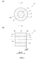
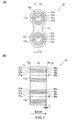
まず、最初に、本発明に係るケーブル用シール部材の第1の実施形態について、図1(A),(B)を参照しつつ説明する。 図1(A)は、本発明に係るケーブル用シール部材の好適な一実施形態を示す正面図であり、図1(B)は、図1(A)のA1−A1断面図である。
[Description of First Embodiment of Cable Sealing Member]
First, a first embodiment of a cable sealing member according to the present invention will be described with reference to FIGS. 1 (A) and 1 (B). FIG. 1A is a front view illustrating a preferred embodiment of a cable sealing member according to the present invention, and FIG. 1B is a cross-sectional view taken along line A1-A1 of FIG.
本発明のケーブル用シール部材10は、デュロメータA硬度が0を超えて30以下、好ましくは、2〜20、さらに好ましくは、2〜15の物性を備えるゴム成形体11から構成される。
The
デュロメータA(Duro-A)硬度、はJIS K6253に基づいて求めることができる。本発明において、デュロメータA硬度が30を超えると、ケーブル用シール部材10と他の部材との接合面におけるシール性が十分ではなく、液密性を保つことが困難となってしまう。
The durometer A (Duro-A) hardness can be determined based on JIS K6253. In the present invention, when the durometer A hardness exceeds 30, the sealing performance at the joint surface between the
具体的なゴム材質としては、例えば、エチレンプロピレンジエン共重合体ゴム(EPDM)、二トリルブタジエンゴム(NBR)、シリコーンゴム、フッ素ゴム、ブタジエンゴム、および、これらの任意の混合物等を挙げることができる。このようなゴム材に、例えば、加硫剤、加硫促進剤、オイル等を加えた後、混練機により混練して、得られたゴム混合物を所定の形状に成型、加硫することにより、所望のゴム成形体を作製することができる。
ゴム硬度の調整には、例えば、ゴムとの相溶性の良いオイルを適当量含有させるようにすれば良い。また、より低分子量のゴム材質を選定することによってもゴム硬度の調整を行なうことができる。
Specific rubber materials include, for example, ethylene propylene diene copolymer rubber (EPDM), nitrile butadiene rubber (NBR), silicone rubber, fluorine rubber, butadiene rubber, and any mixture thereof. it can. For example, after adding a vulcanizing agent, a vulcanization accelerator, oil, etc. to such a rubber material, kneading with a kneader, molding the resulting rubber mixture into a predetermined shape, and vulcanizing, A desired rubber molding can be produced.
For adjusting the rubber hardness, for example, an appropriate amount of oil having good compatibility with rubber may be contained. The rubber hardness can also be adjusted by selecting a lower molecular weight rubber material.
加硫剤としては、硫黄、過酸化物、キノイド、アルキルフェノール・ホルムアルデヒド樹脂やアルキルフェノール・スルフィド樹脂等を挙げることができ、これらは使用されるゴム材質に対応させて適宜選定することができる。加硫促進剤としては、チオウレア系、グアニジン系、チアゾール系、スルフェンアミド系、チウラム系、ジチオカルバミン酸塩系等を使用することができる。また、上記のゴム材質には、必要に応じて老化防止剤、ステアリン酸等の有機脂肪酸、白色充填材(例えば、シリカ、炭酸カルシウム、タルク、クレー)、カーボンブラック等の充填剤等を含有させてもよい。後述するように、ゴム成形体を成形した後に行なわれるリング状スリット部の形成を容易にするためには、カーボンブラックの含有量を抑えて、その減少分を補填するように白色充填材を多目に添加させることが望ましい。 Examples of the vulcanizing agent include sulfur, peroxide, quinoid, alkylphenol / formaldehyde resin, alkylphenol / sulfide resin, and the like, and these can be appropriately selected according to the rubber material to be used. As the vulcanization accelerator, thiourea, guanidine, thiazole, sulfenamide, thiuram, dithiocarbamate, and the like can be used. In addition, the rubber material may contain an anti-aging agent, an organic fatty acid such as stearic acid, a white filler (for example, silica, calcium carbonate, talc, clay), a filler such as carbon black, and the like as necessary. May be. As will be described later, in order to facilitate the formation of the ring-shaped slit portion performed after molding the rubber molded body, a white filler is added so as to compensate for the decrease by suppressing the carbon black content. It is desirable to add it to the eye.
本発明におけるゴム成形体11は、図1(B)に示されるように厚さ方向に対向する第1の平面15と第2の平面16と、前記第1の平面15の周縁15aと第2の平面16の周縁16aを繋ぐ側面部12とを有している。特に、第1の実施形態におけるゴム成形体11は、厚さ方向の中心軸に貫通孔が無い略円柱形状をなしている。ここで、略円柱形状とは、円柱形状の側面部の一部を厚さ方向や円周方向に削り取ったような形状も含む意味である。従って、三角形を含む多角形も含まれる。
As shown in FIG. 1B, the rubber molded
このようなゴム成形体11は、厚さ方向に形成された少なくとも1以上のリング状スリット部17を有している(図示例では1個のみのリング状スリット部17)。
Such a rubber molded
リング状スリット部17は、第1の平面15からスリットの形成が開始されて厚さ方向に延設されており、第2の平面16に到達する手前でスリットが終了して未貫通の部位18が形成されている。
The ring-shaped
この未貫通の部位18は、作業者の手によって、強引に毟り取ることが可能となっており、この毟り取り作業によって、中央の中芯ゴム11aが除去されて、貫通穴を空けることが可能となっている。
The
図1(B)に示されるスリットの最深部から第2の平面16までの距離δは、0.1〜1.0mm程度、好ましくは、0.1〜0.5mmとされる。
The distance δ from the deepest part of the slit shown in FIG. 1B to the
この距離δの値が上限値の1.0mmを超えると、未貫通の部位18を強制的に毟り取って貫通穴を形成させるという作業が困難となってしまう。この一方で、この距離δの値が下限値の0.1mm未満であると、未貫通の部位18の残り厚さがあまりに薄くなってしまい、例えば、搬送中や包装中に未貫通の部位18の一部または全部が切れて貫通穴の一部あるいは全部が形成されてしまうという不都合が生じ得る。つまり、作業者の意図に応じて毟り取ることが可能であるという本来の仕様に反する仕様となってしまう。また、貫通穴を形成せずに閉塞栓として使用するという使い方ができなくなってしまうおそれが生じる。
When the value of the distance δ exceeds the upper limit of 1.0 mm, it becomes difficult to forcibly scrape the
このような第1の実施形態におけるケーブル用シール部材10は、デュロメータA硬度が30以下の極めて低い硬度のゴム成形体からなり、厚さ方向に形成された少なくとも1以上のリング状スリット部17を有しているので、貫通穴を空けて使用することもできるし、貫通穴を形成せずにそのままの状態で閉塞栓として使用することもできる。つまり、1つのケーブル用シール部材10で2種の使い方ができるので、部品の点数を減らすことが可能となる。しかもデュロメータA硬度が30以下の極めて低い硬度のゴム成形体からなるので貫通穴を空けての使用においてもシール性が極めて良好である。
The
なお、本願のデュロメータA硬度が30以下の極めて低い硬度のゴム成形体であって、厚さ方向に形成された少なくとも1以上のリング状スリット部17を有するケーブル用シール部材10は、本願出願人が調査した範囲で市場に存在していないことが確認されている。
Note that the
〔ケーブル用シール部材の第2の実施形態の説明〕
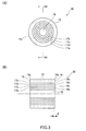
次いで、本発明に係るケーブル用シール部材の第2の実施形態について、図2(A),(B)を参照しつつ説明する。図2(A)は、本発明に係るケーブル用シール部材の好適な一実施形態を示す正面図であり、図2(B)は、図2(A)のA2−A2断面図である。図面における同一符号は実質的に前述した部材と同様の部材を意味する。
[Description of Second Embodiment of Cable Sealing Member]
Next, a second embodiment of the cable sealing member according to the present invention will be described with reference to FIGS. 2 (A) and 2 (B). Fig. 2 (A) is a front view showing a preferred embodiment of the cable sealing member according to the present invention, and Fig. 2 (B) is a cross-sectional view taken along line A2-A2 of Fig. 2 (A). The same reference numerals in the drawings mean substantially the same members as those described above.
第2の実施形態におけるケーブル用シール部材20が前記第1の実施形態のそれと本質的に異なるのは、リング状スリット部17a,17b,17c,17d,17eが、複数個存在するとともに、これらが同心円状に形成されている点にある。
The
すなわち、ゴム成形体11は、厚さ方向に形成された複数の同心円状のリング状スリット部17a,17b,17c,17d,17eを有している。図示例では5個のリング状スリット部が形成されているが、特に、この数に限定されるものではない。また、同心円に配置された各リングの隣接する間隔は、0.5〜2.0mm、好ましくは0.7〜1.2mm程度とされるが特に限定されるものではない。
That is, the rubber molded
これらの各リング状スリット部17a,17b,17c,17d,17eは、それぞれ、第1の平面15からスリットの形成が開始されて厚さ方向に延設されており、第2の平面16に到達する手前でスリットが終了して未貫通の部位18a,18b,18c,18d,18eが形成されている。距離δの設定は上述したとおりである。
Each of the ring-shaped
この未貫通の部位18a,18b,18c,18d,18eは、作業者の手によって、強引に毟り取ることが可能となっており、各リング状スリット部17a,17b,17c,17d,17eのどこを毟り取るかは、使用するケーブルの外径の大きさに合せて適宜選定すればよい。この作業によって、中芯ゴム11aを含む所定の同心円スリット部分が除去されて、貫通穴を空けることが可能となっている。もちろんどこも毟り取らずに、貫通穴を形成せずにそのままの状態で閉塞栓として使用することもできる。
The
ケーブル用シール部材20のデュロメータA硬度の設定や使用するゴム組成については、上述したとおりである。
The setting of the durometer A hardness of the
このような第2の実施形態におけるケーブル用シール部材20は、デュロメータA硬度が30以下の極めて低い硬度のゴム成形体からなり、特に、厚さ方向に形成された複数の同心円状に形成されたリング状スリット部を備えているので、使用するケーブルの外径の大きさに合せて貫通穴の大きさを適宜選んで毟り取って形成することができ、部品点数の削減を図ることができる。しかもシール性が極めて良好である。また、貫通穴を形成せずにそのままの状態で閉塞栓として使用することもでき、これによっても、さらなる部品点数の削減を図ることができる。
The
なお、本願のデュロメータA硬度が30以下の極めて低い硬度のゴム成形体であって、厚さ方向に形成された複数の同心円状に形成されたリング状スリット部を有するケーブル用シール部材20は、本願出願人が調査した範囲で市場に存在していないことが確認されている。
The
〔ケーブル用シール部材の第3の実施形態の説明〕
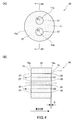
次いで、本発明に係るケーブル用シール部材の第3の実施形態について、図3(A),(B)を参照しつつ説明する。図3(A)は、本発明に係るケーブル用シール部材の好適な一実施形態を示す正面図であり、図3(B)は、図3(A)のA3−A3断面図である。図面における同一符号は実質的に前述した部材と同様の部材を意味する。
[Description of Third Embodiment of Cable Sealing Member]
Next, a third embodiment of the cable sealing member according to the present invention will be described with reference to FIGS. 3 (A) and 3 (B). FIG. 3A is a front view showing a preferred embodiment of the cable sealing member according to the present invention, and FIG. 3B is a cross-sectional view taken along line A3-A3 of FIG. The same reference numerals in the drawings mean substantially the same members as those described above.
図3(A),(B)に示される第3の実施形態におけるケーブル用シール部材30が前記図2(A),(B)に示される第2の実施形態のそれと本質的に異なるのは、厚さ方向の中心軸に貫通孔19が形成されている点にある。そして、この貫通孔19の円形と同心円状にリング状スリット部17b,17c,17d,17eが複数個形成されている。リング状スリット部の個数は、4個の場合が例示されているが、この個数については何ら限定されるものではない。
The
また、同心円状に配置された各リングの隣接する間隔は、上述したとおりにすればよい。
これらの各リング状スリット部17b,17c,17d,17eは、それぞれ、第1の平面15からスリットの形成が開始されて厚さ方向に延設されており、第2の平面16に到達する手前でスリットが終了して未貫通の部位18b,18c,18d,18eとなっている。距離δの設定は上述したとおりである。
Moreover, what is necessary is just to make the space | interval which adjoins each ring arrange | positioned concentrically as above-mentioned.
Each of the ring-shaped
この未貫通の部位18b,18c,18d,18eは、作業者の手によって、強引に毟り取ることが可能となっており、各リング状スリット部17b,17c,17d,17eのどこを毟り取るかは、使用するケーブルの外径の大きさに合せて適宜選定すればよい。この毟り取り作業によって、同心円状のスリット部分が除去されて、貫通穴を空けることが可能となっている。ただし、この場合、そのままの状態で閉塞栓として使用することはできない。
The
ケーブル用シール部材30のデュロメータA硬度の設定や使用するゴム組成については、上述したとおりである。
The setting of the durometer A hardness of the
このような第3の実施形態におけるケーブル用シール部材30は、極めて低い硬度のゴム成形体からなり、特に、厚さ方向に形成された複数の同心円状に形成されたリング状スリット部を備えているので、使用するケーブルの外径の大きさに合せて貫通穴の大きさを適宜選んで毟り取って形成することができ、部品点数の削減を図ることができる。しかもシール性が極めて良好である。
The
なお、本願のデュロメータA硬度が30以下の極めて低い硬度のゴム成形体であって、厚さ方向に形成された複数の同心円状に形成されたリング状スリット部を有するケーブル用シール部材30の存在は、本願出願人が調査した範囲で市場に存在していないことが確認されている。
The presence of a
〔ケーブル用シール部材の第4の実施形態の説明〕
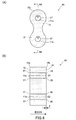
次いで、本発明に係るケーブル用シール部材の第4の実施形態について、図4(A),(B)を参照しつつ説明する。図4(A)は、本発明に係るケーブル用シール部材の好適な一実施形態を示す正面図であり、図4(B)は、図4(A)のA4−A4断面図である。図面における同一符号は実質的に前述した部材と同様の部材を意味する。
[Description of Fourth Embodiment of Cable Sealing Member]
Next, a fourth embodiment of the cable sealing member according to the present invention will be described with reference to FIGS. 4 (A) and 4 (B). FIG. 4A is a front view showing a preferred embodiment of the cable sealing member according to the present invention, and FIG. 4B is a cross-sectional view taken along line A4-A4 of FIG. The same reference numerals in the drawings mean substantially the same members as those described above.
図4(A),(B)に示される第4の実施形態におけるケーブル用シール部材40が前記図1(A),(B)に示される第1の実施形態のそれと本質的に異なるのは、複数のリング状スリット部27,37(図示の例では2個を例示しているが、必ずしもこの個数に限定されるものではない)を第1の平面部15の異なる場所に分散させるように配置させている点にある。すなわち、リング状スリット部27は、厚さ方向の一の軸G1を中心軸として形成されており、リング状スリット部37は、厚さ方向の他の一の軸G2を中心軸として形成されている。G1とG2との間隔は、リング状スリット部27とリング状スリット部37とが交差しないような範囲で適宜定めればよい。
The
これらの各リング状スリット部27、37は、それぞれ、第1の平面15からスリットの形成が開始されて厚さ方向に延設されており、第2の平面16に到達する手前でスリットが終了して未貫通の部位28、38が形成されている。距離δの設定は上述したとおりである。この未貫通の部位28、38は、作業者の手によって、強引に毟り取ることが可能となっている。この作業によって、中芯ゴム11a、11bが除去されて、貫通穴を空けることが可能となっている。もちろん毟り取らずに、貫通穴を形成せずにそのままの状態で閉塞栓として使用することもできる。図示の2つのうち、一方を貫通穴とし、他方を閉塞栓とするようにしてもよい。
Each of the ring-shaped
ケーブル用シール部材40のデュロメータA硬度の設定や使用するゴム組成については、上述したとおりである。
The setting of the durometer A hardness of the
このような第4の実施形態におけるケーブル用シール部材40は、デュロメータA硬度が30以下の極めて低い硬度のゴム成形体からなり、厚さ方向に形成された複数のリング状スリット部27,37を第1の平面部15の異なる場所に分散させるように配置させているので、双方を貫通穴としたり、一方を貫通穴とし他方を閉塞栓とするようにしたりすることができ、部品点数の削減を図ることができる。しかもシール性が極めて良好である。
The
なお、本願の極めて低い硬度のゴム成形体であって、厚さ方向に形成された複数のリング状スリット部を第1の平面部の異なる場所に分散させるように配置させてなるケーブル用シール部材40は、本願出願人が調査した範囲で市場に存在していないことが確認されている。 In addition, it is a rubber molded body of extremely low hardness of the present application, and is a cable sealing member in which a plurality of ring-shaped slit portions formed in the thickness direction are arranged so as to be dispersed in different places on the first plane portion It is confirmed that 40 does not exist in the market within the range investigated by the applicant of the present application.
〔ケーブル用シール部材の第5の実施形態の説明〕
次いで、本発明に係るケーブル用シール部材の第5の実施形態について、図5(A),(B)を参照しつつ説明する。図5(A)は、本発明に係るケーブル用シール部材の好適な一実施形態を示す正面図であり、図5(B)は、図5(A)のA5−A5断面図である。図面における同一符号は実質的に前述した部材と同様の部材を意味する。
[Description of Fifth Embodiment of Cable Sealing Member]
Next, a fifth embodiment of the cable sealing member according to the present invention will be described with reference to FIGS. FIG. 5A is a front view showing a preferred embodiment of a cable sealing member according to the present invention, and FIG. 5B is a cross-sectional view taken along line A5-A5 of FIG. The same reference numerals in the drawings mean substantially the same members as those described above.
図5(A),(B)に示される第5の実施形態におけるケーブル用シール部材50が前記図4(A),(B)に示される第4の実施形態のそれと本質的に異なるのは、複数のリング状スリット部27a,27b,27c,27dが、厚さ方向の一の軸G1を中心軸として同心円状に形成されており、複数のリング状スリット部37a,37b,37c,37dが、厚さ方向の他の一の軸G2を中心軸として同心円状に形成されている点にある。
The
図示例では各々4個のリング状スリット部が形成されているが、特に、この数に限定されるものではない。また、同心円に配置された各リングの隣接する間隔は、0.5〜2.0mm、好ましくは0.7〜1.2mm程度とされるが特に限定されるものではない。 In the illustrated example, four ring-shaped slit portions are formed, but the number is not particularly limited. Moreover, although the space | interval which adjoins each ring arrange | positioned at a concentric circle shall be about 0.5-2.0 mm, Preferably about 0.7-1.2 mm, it is not specifically limited.
G1を中心軸とするリング状スリット部27a,27b,27c,27dは、それぞれ、第1の平面15からスリットの形成が開始されて厚さ方向に延設されており、第2の平面16に到達する手前でスリットが終了して未貫通の部位28a,28b,28c,28dが形成されている。距離δの設定は上述したとおりである。この一方で、G2を中心軸とするリング状スリット部37a,37b,37c,37dは、それぞれ、第1の平面15からスリットの形成が開始されて厚さ方向に延設されており、第2の平面16に到達する手前でスリットが終了して未貫通の部位38a,38b,38c,38dが形成されている。距離δの設定は上述したとおりである。
The ring-shaped
未貫通の部位28a,28b,28c,28dや38a,38b,38c,38dは、作業者の手によって、強引に毟り取ることが可能となっており、各リング状スリット部27a,27b,27c,27d(37a,37b,37c,37d)のどこを毟り取るかは、使用するケーブルの外径の大きさに合せて適宜選定すればよい。
The
この毟り取りの作業によって、中芯ゴム11aを含む同心円状のスリット部分や、中芯ゴム11bを含む同心円状のスリット部分が除去されて、複数の離間した貫通穴を空けることが可能となっている。異なる外径のケーブルの径を複数使用する場合に、個々に対応させた貫通穴とすることもできる。もちろんどこも毟り取らずに、貫通穴を形成せずにそのままの状態で閉塞栓として使用することもできる。
By this scraping operation, the concentric slit portion including the
ケーブル用シール部材50のデュロメータA硬度の設定や使用するゴム組成については、上述したとおりである。
The setting of the durometer A hardness of the
このような第5の実施形態におけるケーブル用シール部材50は、デュロメータA硬度が30以下の極めて低い硬度のゴム成形体からなり、特に、厚さ方向に形成された複数の同心円状に形成されたリング状スリット部を複数セット分散配置させて備えているので、使用するケーブルの外径の大きさに合せて貫通穴の大きさを適宜選んで毟り取って形成することができ、部品点数の削減を図ることができる。しかもシール性が極めて良好である。また、貫通穴を形成せずにそのままの状態で閉塞栓として使用することもでき、これによっても、さらなる部品点数の削減を図ることができる。
The
なお、本願のデュロメータA硬度が30以下の極めて低い硬度のゴム成形体であって、厚さ方向に形成された複数の同心円状に形成されたリング状スリット部を有するケーブル用シール部材50の存在は、本願出願人が調査した範囲で市場に存在していないことが確認されている。
The existence of a
〔ケーブル用シール部材の第6の実施形態の説明〕
次いで、本発明に係るケーブル用シール部材の第6の実施形態について、図6(A),(B)を参照しつつ説明する。図6(A)は、本発明に係るケーブル用シール部材の好適な一実施形態を示す正面図であり、図6(B)は、図6(A)のA6−A6断面図である。図面における同一符号は実質的に前述した部材と同様の部材を意味する。
[Description of Sixth Embodiment of Cable Sealing Member]
Next, a sixth embodiment of the cable sealing member according to the present invention will be described with reference to FIGS. 6 (A) and 6 (B). FIG. 6 (A) is a front view showing a preferred embodiment of the cable sealing member according to the present invention, and FIG. 6 (B) is a cross-sectional view along A6-A6 of FIG. 6 (A). The same reference numerals in the drawings mean substantially the same members as those described above.
図6(A),(B)に示される第6の実施形態におけるケーブル用シール部材60が前記図4(A),(B)に示される第4の実施形態のそれと本質的に異なるのは、特に、ゴム成形体11の外形形状であり、第6の実施形態では正面形状が瓢箪形状となっている。基本的な要部の構成については実質的に同じである。第6の実施形態の方が、ケーブル用シール部材60のゴム材料の使用割合が低く、経済的である。
The
〔ケーブル用シール部材の第7の実施形態の説明〕
次いで、本発明に係るケーブル用シール部材の第7の実施形態について、図7(A),(B)を参照しつつ説明する。図7(A)は、本発明に係るケーブル用シール部材の好適な一実施形態を示す正面図であり、図7(B)は、図7(A)のA7−A7断面図である。図面における同一符号は実質的に前述した部材と同様の部材を意味する。
[Description of Seventh Embodiment of Cable Sealing Member]
Next, a seventh embodiment of the cable sealing member according to the present invention will be described with reference to FIGS. 7 (A) and 7 (B). FIG. 7A is a front view showing a preferred embodiment of a cable sealing member according to the present invention, and FIG. 7B is a cross-sectional view taken along line A7-A7 in FIG. 7A. The same reference numerals in the drawings mean substantially the same members as those described above.
図7(A),(B)に示される第7の実施形態におけるケーブル用シール部材70が前記図5(A),(B)に示される第5の実施形態のそれと本質的に異なるのは、特に、ゴム成形体11の外形形状であり、第7の実施形態では正面形状が瓢箪形状となっている。基本的な要部の構成については実質的に同じである。第7の実施形態の方が、ケーブル用シール部材70のゴム材料の使用割合が低く、経済的である。
The
上述してきたケーブル用シール部材の各実施形態は好適例を示しただけであって、当該実施形態に限定されるものではない。 Each embodiment of the cable sealing member described above is merely a preferred example, and is not limited to this embodiment.
〔ケーブル用シール部材の製造方法の説明〕
次に、上述してきたケーブル用シール部材の製造方法について説明する。
[Description of cable sealing member manufacturing method]
Next, the manufacturing method of the cable sealing member described above will be described.
まず最初に、厚さ方向に対向する第1の平面15と第2の平面16と、第1の平面15の周縁15aと第2の平面16の周縁16aとを繋ぐ側面部12とを有するゴム成形体11であって、デュロメータA硬度が0を超えて30以下であるゴム成形体11を成形する。
First, a rubber having a
ゴム組成物については上述した通りであり、ゴム材に、例えば、加硫剤、加硫促進剤、オイル等を加えた後、混練機により混練して、得られたゴム混合物を所定の形状に成型、加硫することにより、所望のゴム成形体を作製することができる。前述したようにゴム成形体の硬度の調整には、例えば、ゴムとの相溶性の良いオイルを適当量含有させるようにすれば良い。また、より低分子量のゴム材質を選定することによってもゴム硬度の調整を行なうことができる。 The rubber composition is as described above. For example, after adding a vulcanizing agent, a vulcanization accelerator, oil or the like to the rubber material, the rubber composition is kneaded with a kneader, and the resulting rubber mixture is formed into a predetermined shape. A desired rubber molded body can be produced by molding and vulcanization. As described above, for adjusting the hardness of the rubber molded body, for example, an appropriate amount of oil having good compatibility with rubber may be contained. The rubber hardness can also be adjusted by selecting a lower molecular weight rubber material.
次いで、成形されたゴム成形体の側面部12にホルダーを被せた状態で、厚さ方向の一の軸を回転軸としてゴム成形体を回転させつつ、第1の平面15からゴム成形体内部にカット刃を挿入させながらリング状スリット部を形成させていき、第2の平面16に到達する手前でカット刃の挿入を止めて片側未貫通のリング状スリット部を形成させるように構成される。
Next, in a state where the holder is put on the
本発明の製造方法で特に重要なことは、成形されたゴム成形体の側面部12にホルダーを被せた状態でゴム成形体を回転させている点にある。本発明で使用するゴム成形体11は、シール性の向上を図るためにデュロメータA硬度が0を超えて30以下という極めて低い硬度のゴム成形物であり、このものをそのまま回転させた状態で加工すると遠心力でゴムが外方へ変形してしまいリング状スリット部を形成させることが出来ないが、本発明のホルダーはこのような不都合を解消するために用いられているのである。
What is particularly important in the production method of the present invention is that the rubber molded body is rotated in a state where the holder is put on the
ゴム成形体は略円筒形状をなし、その厚さ方向の中心軸には貫通孔が形成されている場合と形成されていない場合との2タイプに別けられる。このようなタイプの相違によって、ゴム成形体を保持する形態は必ずしも同じでない。以下、貫通孔が形成されている場合(例えば、図3に示されるゴム成形体)と貫通孔が形成されていない場合(例えば図1、図2等に示されるゴム成形体)に分けて好適例を挙げて説明する。ただし、本発明の製造方法の要部の作用が発現すればよいのであって、以下に示す好適例に限定されるわけではない。 The rubber molded body has a substantially cylindrical shape, and is divided into two types, that is, a case where a through hole is formed in the central axis in the thickness direction and a case where no through hole is formed. Due to these types of differences, the form of holding the rubber molded body is not necessarily the same. Hereinafter, it is suitable to be divided into a case where a through hole is formed (for example, a rubber molded body shown in FIG. 3) and a case where a through hole is not formed (for example, a rubber molded body shown in FIG. 1, FIG. 2, etc.). An example will be described. However, what is necessary is just to express the effect | action of the principal part of the manufacturing method of this invention, Comprising: It is not necessarily limited to the suitable example shown below.
(好適例1)
最初に、ゴム成形体の厚さ方向の中心軸に貫通孔19が形成されている場合のゴム成形体を保持する好適な形態について、図9(A),(B)を参照しつつ説明する。図9(A)は、本発明に係るケーブル用シール部材を製造する際、片端が回転機構部に固定されるホルダーにケーブル用シール部材がホールドされた好適な状態を示す正面図であり、図9(B)は、図9(A)のA9−A9断面図である。
(Preferred example 1)
First, a preferred embodiment for holding the rubber molded body in the case where the through
ゴム成形体11の厚さ方向の中心軸に貫通孔19が形成されている場合(例えば、図3を参照)には、当該ゴム成形体11を加工する際に使用される加工用ホルダー110は、図9に示されるがごとくである。
When the through
すなわち、ゴム成形体11の貫通孔19に挿入することができるシャフト部112と、シャフト部112の基部112aに位置してシャフト部112に対して垂直な載置平面115aを備える円形フランジ部115と、当該円形フランジ部115のシャフト部112と反対方向に突出した保持シャフト114を有する加工用ホルダー110が準備される。
That is, a
円形フランジ部115の外径は、ゴム成形体11の外径と同程度とすることが好ましい。
It is preferable that the outer diameter of the
このように準備された加工用ホルダー110のシャフト部112にゴム成形体11の貫通孔19を挿入するともに、ゴム成形体11の第2の平面16を円形フランジ部115の載置平面115aと当接させた状態でセットする。しかる後、ゴム成形体11の側面部12に円筒状ホルダー130を被せて図9(A),(B)に示される状態に至る。
The through
この状態で、加工用ホルダー110の保持シャフト114を図示しない回転機械(例えば、旋盤の回転チャック)に固着連結し、シャフト部112を回転軸としてゴム成形体11を回転させつつ、リング状スリット部を形成するためのカット刃140を第1の平面15からゴム成形体11の内部に進入させ、第2の平面16に到達する手前でカット刃140の進入を止めて(距離δの設定範囲内で止める)、未貫通の部位を形成し、いわゆる片側未貫通のリング状スリット部を形成させる。
In this state, the holding
さらに、同心円状に複数の片側未貫通のリング状スリット部を形成させるには第1の平面15からゴム成形体11内部にカット刃140を挿入させる位置を半径方向に間欠的に順次変えることにより、複数の同心円状のリング状スリット部が形成される。
Further, in order to form a plurality of one-side non-penetrating ring-shaped slit portions concentrically, the position where the
シャフト部112を回転軸としてゴム成形体11を回転させる回転速度は、ゴム成形体11の硬度や各種物性、カット刃140の性状等を考慮しながら適宜選定すればよい。
The rotational speed at which the rubber molded
加工用ホルダー110は通常、金属材料から構成することが望ましいが、特に限定されるものではない。樹脂や無機材料等から構成することも可能である。特に、ゴム成形体11の粘着力によるホールド性を向上するために、ゴム成形体11が当接するシャフト部112の表面および円形フランジ部115の載置平面115aは、鏡面としておくことが好ましい。
Usually, the
円筒状ホルダー130は、樹脂から構成することが好ましく、円周の一部に閉周路を切断する分断スリット130a(図9(A)参照)を形成しておくことが好ましい。取り扱い易く操作性に優れるからである。ただし、このような仕様に限定されるわけではない。
The
また、円筒状ホルダー130は、回転による遠心力でゴムが外方へ変形することを防止するように作用するものであるから、円筒状ホルダー130の内径は、ゴム成形体11の外径と実質的に同じ径とすることが望ましい。また、図9(B)に示されるように、円形フランジ部115の外周側面115bをも同時に円筒状ホルダー130で覆うような仕様とすることが望ましい。
Further, the
(好適例2)
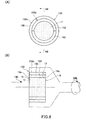
次に、ゴム成形体の厚さ方向の中心軸に貫通孔が無いゴム成形体を保持する好適な形態について、図8(A),(B)を参照しつつ説明する。図8(A)は、本発明に係るケーブル用シール部材を製造する際、片端が回転機構部に固定されるホルダーにケーブル用シール部材がホールドされた好適な状態を示す正面図であり、図8(B)は、図8(A)のA8−A8断面図である。
(Preferred example 2)
Next, a preferred embodiment for holding a rubber molded body having no through hole on the central axis in the thickness direction of the rubber molded body will be described with reference to FIGS. 8 (A) and 8 (B). FIG. 8A is a front view showing a preferred state in which the cable sealing member is held by a holder whose one end is fixed to the rotating mechanism portion when the cable sealing member according to the present invention is manufactured. 8 (B) is a cross-sectional view taken along line A8-A8 in FIG. 8 (A).
ゴム成形体11の厚さ方向の中心軸に貫通孔が形成されていない場合(例えば、図1,2を参照)には、当該ゴム成形体11を加工する際に使用される加工用ホルダー150は、図8に示されるごとくである。
When a through hole is not formed on the central axis in the thickness direction of the rubber molded body 11 (see, for example, FIGS. 1 and 2), a
すなわち、ゴム成形体11の側面部12に被着させる円筒状のホルダー153と、この上に被着させる円筒状の外ホルダー155を備えている。
That is, a
本実施例の場合、円筒状のホルダー153は、複数割りされた円筒状ホルダー(図示例では2つ割りされている)を元の円筒状に組み合わせてゴム成形体の側面部12に被着させているが、必ずしもこの構造に限定されるわけではない。また、外ホルダー155は、円周の一部に閉周路を切断する分断スリット155aが形成された金属ホルダーとすることが好ましい。円筒状のホルダー153の内径は、ゴム成形体11の外径と同程度とすることが好ましい。外ホルダー155の内径は、円筒状のホルダー153の外径と同程度とすることが好ましい。
In the case of the present embodiment, the
この準備された加工用ホルダー150を用いて、ゴム成形体11の側面部12に、複数割りされた円筒状のホルダー153を元の円筒状に組み合わせて被着させ、この円筒状のホルダー153の上にさらに、外ホルダー155を被着させ、当該外ホルダー155の外周155bを回転機械のチャック(例えば、旋盤のチャック)で挟むように固着連結させて、図8(B)に示される状態に至る。
Using the
この状態で、回転機械を回転させてゴム成形体11を回転させつつ、リング状スリット部を形成するためのカット刃140を第1の平面15からゴム成形体11の内部に進入させ、第2の平面16に到達する手前でカット刃140の進入を止めて(距離δの設定範囲内で止める)、未貫通の部位を形成し、いわゆる片側未貫通のリング状スリット部を形成させる(例えば、図1参照)。
In this state, the rotary machine is rotated to rotate the rubber molded
さらに、同心円状に複数の片側未貫通のリング状スリット部を形成させるには第1の平面15からゴム成形体11内部にカット刃140を挿入させる位置を半径方向に間欠的に順次変えることにより、複数の同心円状のリング状スリット部が形成される(例えば、図2参照)。
Further, in order to form a plurality of one-side non-penetrating ring-shaped slit portions concentrically, the position where the
ゴム成形体11を回転させる回転速度は、ゴム成形体11の硬度や各種物性、カット刃140の性状等を考慮しながら適宜選定すればよい。
The rotational speed for rotating the rubber molded
(好適例3)
上記の好適例1,2とは異なり、例えば、図6や図7に示されるように、一のリング状スリット部が、厚さ方向の一の軸G1を中心軸として形成されており、他の一のリング状スリット部が、厚さ方向の他の一の軸G2を中心軸として形成されている場合の製造方法について、図10(A),(B)を参照しつつ説明する。
(Preferred example 3)
Unlike the above-mentioned preferred examples 1 and 2, for example, as shown in FIG. 6 and FIG. 7, one ring-shaped slit portion is formed with one axis G1 in the thickness direction as the central axis. A manufacturing method in the case where one ring-shaped slit portion is formed with the other axis G2 in the thickness direction as the central axis will be described with reference to FIGS. 10 (A) and 10 (B).
図10(A)は、本発明に係るケーブル用シール部材を製造する際、片端が回転機構部に固定されるホルダーにケーブル用シール部材がホールドされた好適な状態を示す正面図であり、図10(B)は、図10(A)のA10−A10断面図である。 FIG. 10 (A) is a front view showing a preferred state in which the cable seal member is held by a holder whose one end is fixed to the rotation mechanism when manufacturing the cable seal member according to the present invention. 10 (B) is a cross-sectional view taken along line A10-A10 in FIG. 10 (A).
例えば、図6や図7に示されるゴム成形体11を加工する際に使用される加工用ホルダー180の好適な一例が図10に示される。すなわち、図10に示される加工用ホルダー180は、円盤状のフランジ板185と、このフランジ板185の一方の面181側に形成される凹部188と、フランジ板185の他方の面182に形成された保持シャフト189とを備えている。
For example, FIG. 10 shows a preferred example of a
一方の面181側に形成される凹部188は、図示のごとくゴム成形体11の第2の平面16(第2の平面16)と側面部12とが密着して収納されるような形態をなしている。すなわち、ゴム成形体11は凹部181内にすっぽりと嵌着される。それゆえ、ゴム成形体11の側面部12はホルダーを被せた状態と実質的に同じになっており、回転させた状態で加工しても遠心力でゴムが外方へ変形してしまうという不都合は生じない。
The
また、保持シャフト189の中心軸と、厚さ方向の他の一の軸G2とは一致するように設定される。
Further, the central axis of the holding
この準備された加工用ホルダー180を用いて、ゴム成形体11を凹部188内に嵌着して収納し、図10(A),(B)に示される状態に至る。
Using the
この状態で、加工用ホルダー180の保持シャフト189を図示しない回転機械(例えば、旋盤の回転チャック)に固着連結し、シャフト部189を回転軸(軸G2と同じ)としてゴム成形体11を回転させつつ、リング状スリット部を形成するためのカット刃140を第1の平面15からゴム成形体11の内部に進入させ、第2の平面16に到達する手前でカット刃140の進入を止めて(距離δの設定範囲内で止める)、未貫通の部位を形成し、いわゆる片側未貫通のリング状スリット部を形成させる。
In this state, the holding
さらに、同心円状に複数の片側未貫通のリング状スリット部を形成させるには、第1の平面15からゴム成形体11内部にカット刃140を挿入させる位置を半径方向に間欠的に順次変えることにより、複数の同心円状のリング状スリット部が形成される。
Furthermore, in order to form a plurality of one-side non-penetrating ring-shaped slit portions concentrically, the position at which the
次いで、ゴム成形体11を一旦、凹部188から外して、ゴム成形体11の上下位置を反対にセットする。これによって、G1がG2の位置に来るので、回転中心がG1となり、上記と同様にシャフト部189を回転軸(軸G1と同じ)としてゴム成形体11を回転させつつ、リング状スリット部を形成するためのカット刃140を第1の平面15からゴム成形体11の内部に進入させ、第2の平面16に到達する手前でカット刃140の進入を止めて(距離δの設定範囲内で止める)、未貫通の部位を形成し、いわゆる片側未貫通のリング状スリット部を形成させる。
Next, the rubber molded
上記の操作は、以下の操作と実質的に同じである。すなわち、成形されたゴム成形体の側面部にホルダーを被せた状態で、厚さ方向の一の軸を回転軸としてゴム成形体を回転させつつ、第1の平面部からゴム成形体内部にカット刃を挿入させながらリング状スリット部を形成させていき、第2の平面に到達する手前でカット刃の挿入を止めて片側未貫通のリング状スリット部を形成させ、次いで、成形されたゴム成形体の側面部にホルダーを被せた状態で、厚さ方向の他の一の軸を回転軸としてゴム成形体を回転させつつ、第1の平面部からゴム成形体内部にカット刃を挿入させながらリング状スリット部を形成させていき、第2の平面に到達する手前でカット刃の挿入を止めて片側未貫通のリング状スリット部を形成させ、少なくとも複数のリング状スリット部を第1の平面部の異なる場所に分散させるように配置させた状態を形成しているのである。 The above operation is substantially the same as the following operation. In other words, with the holder placed on the side surface of the molded rubber molded body, the rubber molded body is rotated about one axis in the thickness direction as the rotation axis, and cut from the first flat portion into the rubber molded body. The ring-shaped slit part is formed while inserting the blade, the insertion of the cutting blade is stopped before reaching the second plane to form a ring-shaped slit part not penetrating on one side, and then molded rubber molding With the holder on the side surface of the body, the rubber molded body is rotated with the other axis in the thickness direction as the rotation axis, and the cutting blade is inserted into the rubber molded body from the first plane portion The ring-shaped slit portion is formed, the insertion of the cutting blade is stopped before reaching the second plane, and the one-side unpenetrated ring-shaped slit portion is formed, and at least the plurality of ring-shaped slit portions are formed on the first plane. Different places in the department With each other to form a state of being arranged to disperse.
上記のごとくゴム成形体11の上下位置を反対にセットすることによって、回転軸をG1とG2、相互に交換してもよいし、図示していないがシャフト部189を着脱可能として取り付け位置をG1とG2の相互の2つの位置に変更できるようにしてもよい。
As described above, by setting the upper and lower positions of the rubber molded
なお、図4および図5に示されるケーブル用シール部材40および50の製造方法についても、基本的な製法は図10に示される手法に従えばよいので、ここでの詳細な説明は省略する。
In addition, since the basic manufacturing method should just follow the method shown by FIG. 10 also about the manufacturing method of the
以上の説明から分かるように、本発明のケーブル用シール部材は、ケーブル保護ケース内へ外部からの液体の浸入を防止するために、ケーブル保護ケースの端部に配置されるケーブル用シール部材であって、該ケーブル用シール部材は、デュロメータA硬度が0を超えて30以下であるゴム成形体からなり、前記ゴム成形体は、厚さ方向に対向する第1の平面と第2の平面と、前記第1の平面の周縁と第2の平面の周縁とを繋ぐ側面部とを有し、前記ゴム成形体は、厚さ方向に形成された少なくとも1以上のリング状スリット部を有し、前記リング状スリット部は、前記第1の平面からスリットの形成が開始されて厚さ方向に延設されており、第2の平面に到達する手前でスリットが終了して未貫通の部位となっているように構成されている。従って、シール性が極めて良好であるとともに、除去可能なリング状スリット部を備えるので、部品点数の削減を図ることができる。多品種を常に持ち歩く必要性もなく、作業性の向上に大きく寄与することができる。 As can be seen from the above description, the cable seal member of the present invention is a cable seal member disposed at the end of the cable protection case in order to prevent liquid from entering the cable protection case from the outside. The cable sealing member is made of a rubber molded body having a durometer A hardness of more than 0 and 30 or less, and the rubber molded body has a first plane and a second plane opposed to each other in the thickness direction, A side surface portion connecting a peripheral edge of the first plane and a peripheral edge of the second plane, and the rubber molded body has at least one ring-shaped slit portion formed in a thickness direction, The ring-shaped slit portion is formed in the thickness direction after the slit formation is started from the first plane, and the slit ends before reaching the second plane to become an unpenetrated part. Is configured toAccordingly, the sealing performance is extremely good and the ring-shaped slit portion that can be removed is provided, so that the number of parts can be reduced. There is no need to always carry multiple varieties, which can greatly contribute to the improvement of workability.
また、このようなケーブル用シール部材の製造方法は、厚さ方向に対向する第1の平面と第2の平面と、前記第1の平面の周縁と第2の平面の周縁とを繋ぐ側面部とを有するゴム成形体であって、デュロメータA硬度が0を超えて30以下であるゴム成形体を成形し、成形されたゴム成形体の側面部にホルダーを被せた状態で、厚さ方向の一の軸を回転軸としてゴム成形体を回転させつつ、第1の平面からゴム成形体内部にカット刃を挿入させながらリング状スリット部を形成させていき、第2の平面に到達する手前でカット刃の挿入を止めて片側未貫通のリング状スリット部を形成させるように構成される。 Moreover, the manufacturing method of such a cable sealing member includes a first plane and a second plane that face each other in the thickness direction, and a side surface that connects the periphery of the first plane and the periphery of the second plane. A rubber molded body having a durometer A hardness of more than 0 and 30 or less, and a side portion of the molded rubber molded body is covered with a holder. While rotating the rubber molded body around one axis as a rotation axis, the ring-shaped slit portion is formed while inserting the cutting blade into the rubber molded body from the first plane, before reaching the second plane. The insertion of the cutting blade is stopped to form a ring-shaped slit portion that is not penetrated on one side.
従って、従来、デュロメータA硬度が30以下の低硬度のゴムでは加工することが出来なかったリング状スリット部を安定に加工することができ、シール性に優れ、除去可能なリング状スリット部を備える新規なケーブル用シール部材を提供することができるという効果が発現する。 Therefore, a ring-shaped slit portion that could not be processed with a low hardness rubber having a durometer A hardness of 30 or less can be stably processed, and has a ring-shaped slit portion that has excellent sealing properties and can be removed. The effect that the novel sealing member for cables can be provided expresses.
本発明の産業上の利用可能性として、本発明は、ケーブルを用いた一般的な通信技術分野の技術に利用することができる。 As the industrial applicability of the present invention, the present invention can be used for the technology in the general communication technology field using a cable.
10,20,30,40,50,60,70…ケーブル用シール部材
12…側面部
15…第1の平面
16…第2の平面
17,27,37…リング状スリット部
130,153,155…ホルダー
140…カット刃
10, 20, 30, 40, 50, 60, 70 ...
Claims (10)
当該方法は、
厚さ方向に対向する第1の平面と第2の平面と、前記第1の平面の周縁と第2の平面の周縁とを繋ぐ側面部とを有するゴム成形体であって、デュロメータA硬度が0を超えて30以下であるゴム成形体を成形し、
成形されたゴム成形体の側面部にホルダーを被せた状態で、厚さ方向の一の軸を回転軸としてゴム成形体を回転させつつ、第1の平面からゴム成形体内部にカット刃を挿入させながらリング状スリット部を形成させていき、第2の平面に到達する手前でカット刃の挿入を止めて片側未貫通のリング状スリット部を形成させることを特徴とするケーブル用シール部材の製造方法。 In order to prevent the intrusion of liquid from the outside into the cable protection case, a method for manufacturing a cable sealing member disposed at the end of the cable protection case ,
The method is
A rubber molded body having a first plane and a second plane opposed to each other in the thickness direction, and a side surface connecting the peripheral edge of the first plane and the peripheral edge of the second plane, and having a durometer A hardness. Molding a rubber molding that is greater than 0 and 30 or less,
Insert the cutting blade into the rubber molding from the first plane while rotating the rubber molding around one axis in the thickness direction with the holder on the side part of the molded rubber molding. A ring-shaped slit portion is formed while the ring-shaped slit portion is formed, and the insertion of the cutting blade is stopped before reaching the second plane to form a ring-shaped slit portion that is not penetrated on one side. Method.
前記貫通孔に挿入することができるシャフト部と、シャフト部の基部に位置してシャフト部に対して垂直な載置平面を備える円形フランジ部と、当該円形フランジ部のシャフト部と反対方向に突出した保持シャフトを有する加工用ホルダーを準備し、
前記加工用ホルダーのシャフト部にゴム成形体の貫通孔を挿入するともに、ゴム成形体の第2の平面を円形フランジ部の載置平面と当接させた状態でセットし、ゴム成形体の側面部に円筒状ホルダーを被せた状態で、前記加工用ホルダーの保持シャフトを回転機械に固着連結し、シャフト部を回転軸としてゴム成形体を回転させつつ、片側未貫通のリング状スリット部を形成させる請求項1に記載のケーブル用シール部材の製造方法。 The rubber molded body has a substantially cylindrical shape, and a through hole is formed in the central axis in the thickness direction,
A shaft portion that can be inserted into the through hole, a circular flange portion that is located at the base portion of the shaft portion and has a mounting plane perpendicular to the shaft portion, and protrudes in a direction opposite to the shaft portion of the circular flange portion Prepare a processing holder with a holding shaft
Insert the through hole of the rubber molded body into the shaft portion of the processing holder and set the second flat surface of the rubber molded body in contact with the mounting plane of the circular flange portion. With the cylindrical holder on the part, the holding shaft of the processing holder is fixedly connected to the rotating machine, and the rubber part is rotated around the shaft part as a rotating shaft, forming a ring slit part that is not penetrated on one side. The manufacturing method of the sealing member for cables of Claim 1 .
ゴム成形体の側面部に、円筒状のホルダーを被着させ、この円筒状のホルダーの上にさらに、外ホルダーを被着させ、当該外ホルダーの外周を回転機械のチャックで挟むように固着連結させ、ゴム成形体を回転させつつ、片側未貫通のリング状スリット部を形成させる請求項1に記載のケーブル用シール部材の製造方法。 The rubber molded body has a substantially cylindrical shape with no through hole in the central axis in the thickness direction,
A cylindrical holder is attached to the side of the rubber molded body, and an outer holder is further attached to the cylindrical holder, and the outer periphery of the outer holder is fixedly connected so as to be sandwiched between chucks of a rotating machine. The method for manufacturing a cable sealing member according to claim 1 , wherein a ring-shaped slit portion not penetrating on one side is formed while rotating the rubber molded body.
次いで、成形されたゴム成形体の側面部にホルダーを被せた状態で、厚さ方向の他の一の軸を回転軸としてゴム成形体を回転させつつ、第1の平面からゴム成形体内部にカット刃を挿入させながらリング状スリット部を形成させていき、第2の平面に到達する手前でカット刃の挿入を止めて片側未貫通のリング状スリット部を形成させ、
複数のリング状スリット部を第1の平面の異なる場所に分散させるように配置させてなる請求項1に記載のケーブル用シール部材の製造方法。 Insert the cutting blade into the rubber molding from the first plane while rotating the rubber molding around one axis in the thickness direction with the holder on the side part of the molded rubber molding. The ring-shaped slit part is formed while stopping the insertion of the cutting blade just before reaching the second plane, and the one-side non-penetrating ring-shaped slit part is formed,
Next, in a state where the holder is put on the side surface portion of the molded rubber molded body, the rubber molded body is rotated with the other axis in the thickness direction as the rotation axis, and from the first plane to the inside of the rubber molded body. The ring-shaped slit part is formed while inserting the cutting blade, and the insertion of the cutting blade is stopped before reaching the second plane to form a ring-shaped slit part not penetrating on one side,
The manufacturing method of the sealing member for cables of Claim 1 arrange | positioned so that a some ring-shaped slit part may be disperse | distributed to the different place of a 1st plane.
前記リング状スリット部は、厚さ方向の他の一の軸を回転軸として同心円状に複数個形成されている請求項9に記載のケーブル用シール部材の製造方法。 A plurality of the ring-shaped slit portions are formed concentrically with one axis in the thickness direction as a rotation axis,
The said ring-shaped slit part is a manufacturing method of the sealing member for cables of Claim 9 currently formed in multiple numbers concentrically by making another axis | shaft of the thickness direction into a rotating shaft.
Priority Applications (4)
| Application Number | Priority Date | Filing Date | Title |
|---|---|---|---|
| JP2011113179A JP5162002B2 (en) | 2011-05-20 | 2011-05-20 | Method for manufacturing cable sealing member |
| CN201280024446.7A CN103534891B (en) | 2011-05-20 | 2012-04-25 | The manufacture method of seal member for cable |
| US14/115,704 US8852477B2 (en) | 2011-05-20 | 2012-04-25 | Cable-sealing member and its producing method |
| PCT/JP2012/061627 WO2012160954A1 (en) | 2011-05-20 | 2012-04-25 | Seal member for cable and manufacturing method therefor |
Applications Claiming Priority (1)
| Application Number | Priority Date | Filing Date | Title |
|---|---|---|---|
| JP2011113179A JP5162002B2 (en) | 2011-05-20 | 2011-05-20 | Method for manufacturing cable sealing member |
Publications (2)
| Publication Number | Publication Date |
|---|---|
| JP2012244790A JP2012244790A (en) | 2012-12-10 |
| JP5162002B2 true JP5162002B2 (en) | 2013-03-13 |
Family
ID=47217037
Family Applications (1)
| Application Number | Title | Priority Date | Filing Date |
|---|---|---|---|
| JP2011113179A Expired - Fee Related JP5162002B2 (en) | 2011-05-20 | 2011-05-20 | Method for manufacturing cable sealing member |
Country Status (4)
| Country | Link |
|---|---|
| US (1) | US8852477B2 (en) |
| JP (1) | JP5162002B2 (en) |
| CN (1) | CN103534891B (en) |
| WO (1) | WO2012160954A1 (en) |
Families Citing this family (9)
| Publication number | Priority date | Publication date | Assignee | Title |
|---|---|---|---|---|
| AU360052S (en) * | 2014-05-07 | 2015-01-21 | Mct Brattberg Ab | A cable wire or pipe sealing device |
| EP2975713B1 (en) * | 2014-07-18 | 2021-03-24 | CMP Products Limited | Sealing device for sealing engagement with an elongate object |
| JP5890927B1 (en) * | 2015-03-27 | 2016-03-22 | 星和電機株式会社 | Cable holder sleeve and cable holder using the same |
| SE539904C2 (en) * | 2015-12-18 | 2018-01-09 | Roxtec Ab | Module of a seal or transition |
| CN106924779A (en) * | 2015-12-30 | 2017-07-07 | 博西华电器(江苏)有限公司 | Disinfection cabinet |
| CN109054396B (en) * | 2018-07-27 | 2020-12-11 | 国网河南省电力公司镇平县供电公司 | Cable plugging material and preparation method thereof |
| CN110061459A (en) * | 2019-04-02 | 2019-07-26 | 浙江中财管道科技股份有限公司 | A kind of arc-shaped different lines under floor fitting system |
| US20220337044A1 (en) * | 2019-09-24 | 2022-10-20 | Commscope Technologies Llc | Composite cable seal |
| EP4059105A4 (en) * | 2019-11-11 | 2023-12-06 | CommScope Technologies LLC | Cable sealing arrangement for an enclosure |
Family Cites Families (6)
| Publication number | Priority date | Publication date | Assignee | Title |
|---|---|---|---|---|
| US5048382A (en) * | 1989-08-23 | 1991-09-17 | Mar Don Corporation | Method for making elastomeric sealing device |
| TW307801B (en) * | 1992-03-19 | 1997-06-11 | Minnesota Mining & Mfg | |
| GB9317871D0 (en) * | 1993-08-27 | 1993-10-13 | Rose Walter Gmbh & Co Kg | Sealing member |
| JP2001253983A (en) * | 2000-03-10 | 2001-09-18 | Sumitomo Rubber Ind Ltd | Rubber composition having low elastic modulus, and sealing material using the same |
| JP2005005042A (en) * | 2003-06-10 | 2005-01-06 | Jst Mfg Co Ltd | Cable with waterproofing plug, connector cable with waterproofing plug, manufacturing method of cable with waterproofing plug, and terminal fitting connecting structure |
| WO2008073524A2 (en) * | 2006-07-10 | 2008-06-19 | Mar Don Corporation | Improved method for making an elastomeric sealing device |
-
2011
- 2011-05-20 JP JP2011113179A patent/JP5162002B2/en not_active Expired - Fee Related
-
2012
- 2012-04-25 US US14/115,704 patent/US8852477B2/en not_active Expired - Fee Related
- 2012-04-25 CN CN201280024446.7A patent/CN103534891B/en not_active Expired - Fee Related
- 2012-04-25 WO PCT/JP2012/061627 patent/WO2012160954A1/en active Application Filing
Also Published As
| Publication number | Publication date |
|---|---|
| CN103534891B (en) | 2016-08-17 |
| US20140077409A1 (en) | 2014-03-20 |
| CN103534891A (en) | 2014-01-22 |
| JP2012244790A (en) | 2012-12-10 |
| WO2012160954A1 (en) | 2012-11-29 |
| US8852477B2 (en) | 2014-10-07 |
Similar Documents
| Publication | Publication Date | Title |
|---|---|---|
| JP5162002B2 (en) | Method for manufacturing cable sealing member | |
| WO2011056840A2 (en) | Round cutting insert with anti-rotation feature | |
| EP1840412B1 (en) | Bearing device equipped with resin-made pulley | |
| BRPI0808180A2 (en) | CONTAINER | |
| KR20110122824A (en) | Guide arrangement for a cutting tool and cutting tool including a guide arrangement | |
| BR112016026476B1 (en) | CHAIN BLOCK | |
| CA2773722A1 (en) | Method and apparatus for pipe-end shaving | |
| KR101268909B1 (en) | damper for semiconductor equipment | |
| US10220358B2 (en) | Mixing device for joint compound | |
| JP2010014143A (en) | Sealing device | |
| US8857819B2 (en) | Mechanical seal | |
| US8753077B2 (en) | Slinger shield structure | |
| JP6755622B2 (en) | Sealing structure of the opening in the transmission case | |
| US8459655B2 (en) | Sealing device | |
| JP2011033065A (en) | Boot for constant velocity joint | |
| JP4084729B2 (en) | Resin seal ring | |
| KR100976235B1 (en) | Apparatus for cutting burr | |
| KR101856643B1 (en) | Arbor nut | |
| JP2020051555A (en) | Seal ring | |
| BR102018008536B1 (en) | ROTATING APPLIANCE | |
| KR200388583Y1 (en) | Washer for protecting the cutter body | |
| JP2009144823A (en) | Sealing device | |
| JP5624725B2 (en) | Oil seal protection structure | |
| KR200332137Y1 (en) | Anti-swirl packing ring for diaphragm of steam turbine | |
| KR20150126486A (en) | Cuver for multifunctiional vegetable cutter |
Legal Events
| Date | Code | Title | Description |
|---|---|---|---|
| A621 | Written request for application examination |
Free format text: JAPANESE INTERMEDIATE CODE: A621 Effective date: 20121002 |
|
| A871 | Explanation of circumstances concerning accelerated examination |
Free format text: JAPANESE INTERMEDIATE CODE: A871 Effective date: 20121002 |
|
| A975 | Report on accelerated examination |
Free format text: JAPANESE INTERMEDIATE CODE: A971005 Effective date: 20121018 |
|
| A131 | Notification of reasons for refusal |
Free format text: JAPANESE INTERMEDIATE CODE: A131 Effective date: 20121023 |
|
| A521 | Request for written amendment filed |
Free format text: JAPANESE INTERMEDIATE CODE: A523 Effective date: 20121112 |
|
| TRDD | Decision of grant or rejection written | ||
| A01 | Written decision to grant a patent or to grant a registration (utility model) |
Free format text: JAPANESE INTERMEDIATE CODE: A01 Effective date: 20121204 |
|
| A61 | First payment of annual fees (during grant procedure) |
Free format text: JAPANESE INTERMEDIATE CODE: A61 Effective date: 20121214 |
|
| R150 | Certificate of patent or registration of utility model |
Ref document number: 5162002 Country of ref document: JP Free format text: JAPANESE INTERMEDIATE CODE: R150 Free format text: JAPANESE INTERMEDIATE CODE: R150 |
|
| FPAY | Renewal fee payment (event date is renewal date of database) |
Free format text: PAYMENT UNTIL: 20151221 Year of fee payment: 3 |
|
| S533 | Written request for registration of change of name |
Free format text: JAPANESE INTERMEDIATE CODE: R313533 |
|
| R350 | Written notification of registration of transfer |
Free format text: JAPANESE INTERMEDIATE CODE: R350 |
|
| R250 | Receipt of annual fees |
Free format text: JAPANESE INTERMEDIATE CODE: R250 |
|
| R250 | Receipt of annual fees |
Free format text: JAPANESE INTERMEDIATE CODE: R250 |
|
| LAPS | Cancellation because of no payment of annual fees |