JP5160901B2 - Elevator load bearing member with jacket having at least one outer surface to increase traction capability - Google Patents
Elevator load bearing member with jacket having at least one outer surface to increase traction capability Download PDFInfo
- Publication number
- JP5160901B2 JP5160901B2 JP2007555063A JP2007555063A JP5160901B2 JP 5160901 B2 JP5160901 B2 JP 5160901B2 JP 2007555063 A JP2007555063 A JP 2007555063A JP 2007555063 A JP2007555063 A JP 2007555063A JP 5160901 B2 JP5160901 B2 JP 5160901B2
- Authority
- JP
- Japan
- Prior art keywords
- elevator system
- manufacturing
- load bearing
- load
- jacket
- Prior art date
- Legal status (The legal status is an assumption and is not a legal conclusion. Google has not performed a legal analysis and makes no representation as to the accuracy of the status listed.)
- Active
Links
- 239000000463 material Substances 0.000 claims description 34
- 238000000034 method Methods 0.000 claims description 34
- 229920002635 polyurethane Polymers 0.000 claims description 28
- 239000004814 polyurethane Substances 0.000 claims description 28
- 238000004519 manufacturing process Methods 0.000 claims description 20
- 239000010410 layer Substances 0.000 claims description 18
- 239000002344 surface layer Substances 0.000 claims description 14
- 150000001408 amides Chemical class 0.000 claims description 13
- 229920000642 polymer Polymers 0.000 claims description 13
- 239000000126 substance Substances 0.000 claims description 13
- 238000004140 cleaning Methods 0.000 claims description 5
- 238000005498 polishing Methods 0.000 claims description 5
- XLYOFNOQVPJJNP-UHFFFAOYSA-N water Substances O XLYOFNOQVPJJNP-UHFFFAOYSA-N 0.000 claims description 5
- 238000003486 chemical etching Methods 0.000 claims description 4
- POAOYUHQDCAZBD-UHFFFAOYSA-N 2-butoxyethanol Chemical compound CCCCOCCO POAOYUHQDCAZBD-UHFFFAOYSA-N 0.000 claims description 3
- 238000005299 abrasion Methods 0.000 claims description 3
- 238000000227 grinding Methods 0.000 claims description 3
- 239000000203 mixture Substances 0.000 claims description 3
- JOYRKODLDBILNP-UHFFFAOYSA-N Ethyl urethane Chemical compound CCOC(N)=O JOYRKODLDBILNP-UHFFFAOYSA-N 0.000 description 6
- 238000007373 indentation Methods 0.000 description 6
- 238000010586 diagram Methods 0.000 description 5
- 229920002803 thermoplastic polyurethane Polymers 0.000 description 5
- 230000008901 benefit Effects 0.000 description 4
- 238000000465 moulding Methods 0.000 description 4
- 239000004433 Thermoplastic polyurethane Substances 0.000 description 3
- 238000001125 extrusion Methods 0.000 description 3
- 239000001993 wax Substances 0.000 description 3
- RTZKZFJDLAIYFH-UHFFFAOYSA-N Diethyl ether Chemical compound CCOCC RTZKZFJDLAIYFH-UHFFFAOYSA-N 0.000 description 2
- 229910000831 Steel Inorganic materials 0.000 description 2
- 239000000654 additive Substances 0.000 description 2
- 238000007689 inspection Methods 0.000 description 2
- 239000007788 liquid Substances 0.000 description 2
- 239000006082 mold release agent Substances 0.000 description 2
- 239000010959 steel Substances 0.000 description 2
- PXGOKWXKJXAPGV-UHFFFAOYSA-N Fluorine Chemical compound FF PXGOKWXKJXAPGV-UHFFFAOYSA-N 0.000 description 1
- 239000006057 Non-nutritive feed additive Substances 0.000 description 1
- 239000004677 Nylon Substances 0.000 description 1
- 239000000853 adhesive Substances 0.000 description 1
- 230000001070 adhesive effect Effects 0.000 description 1
- 125000001931 aliphatic group Chemical group 0.000 description 1
- 229920006231 aramid fiber Polymers 0.000 description 1
- 239000000306 component Substances 0.000 description 1
- 238000010276 construction Methods 0.000 description 1
- 230000007423 decrease Effects 0.000 description 1
- 230000000694 effects Effects 0.000 description 1
- 150000002148 esters Chemical class 0.000 description 1
- 230000002349 favourable effect Effects 0.000 description 1
- 229910052731 fluorine Inorganic materials 0.000 description 1
- 239000011737 fluorine Substances 0.000 description 1
- 238000009434 installation Methods 0.000 description 1
- 238000012986 modification Methods 0.000 description 1
- 230000004048 modification Effects 0.000 description 1
- 229920001778 nylon Polymers 0.000 description 1
- 238000003672 processing method Methods 0.000 description 1
- 239000002994 raw material Substances 0.000 description 1
- 229920001169 thermoplastic Polymers 0.000 description 1
- 239000004416 thermosoftening plastic Substances 0.000 description 1
Images


Classifications
-
- D—TEXTILES; PAPER
- D07—ROPES; CABLES OTHER THAN ELECTRIC
- D07B—ROPES OR CABLES IN GENERAL
- D07B5/00—Making ropes or cables from special materials or of particular form
- D07B5/005—Making ropes or cables from special materials or of particular form characterised by their outer shape or surface properties
- D07B5/006—Making ropes or cables from special materials or of particular form characterised by their outer shape or surface properties by the properties of an outer surface polymeric coating
-
- B—PERFORMING OPERATIONS; TRANSPORTING
- B29—WORKING OF PLASTICS; WORKING OF SUBSTANCES IN A PLASTIC STATE IN GENERAL
- B29C—SHAPING OR JOINING OF PLASTICS; SHAPING OF MATERIAL IN A PLASTIC STATE, NOT OTHERWISE PROVIDED FOR; AFTER-TREATMENT OF THE SHAPED PRODUCTS, e.g. REPAIRING
- B29C59/00—Surface shaping of articles, e.g. embossing; Apparatus therefor
- B29C59/02—Surface shaping of articles, e.g. embossing; Apparatus therefor by mechanical means, e.g. pressing
- B29C59/04—Surface shaping of articles, e.g. embossing; Apparatus therefor by mechanical means, e.g. pressing using rollers or endless belts
-
- B—PERFORMING OPERATIONS; TRANSPORTING
- B66—HOISTING; LIFTING; HAULING
- B66B—ELEVATORS; ESCALATORS OR MOVING WALKWAYS
- B66B7/00—Other common features of elevators
- B66B7/06—Arrangements of ropes or cables
- B66B7/062—Belts
-
- B—PERFORMING OPERATIONS; TRANSPORTING
- B29—WORKING OF PLASTICS; WORKING OF SUBSTANCES IN A PLASTIC STATE IN GENERAL
- B29C—SHAPING OR JOINING OF PLASTICS; SHAPING OF MATERIAL IN A PLASTIC STATE, NOT OTHERWISE PROVIDED FOR; AFTER-TREATMENT OF THE SHAPED PRODUCTS, e.g. REPAIRING
- B29C59/00—Surface shaping of articles, e.g. embossing; Apparatus therefor
- B29C59/02—Surface shaping of articles, e.g. embossing; Apparatus therefor by mechanical means, e.g. pressing
- B29C2059/027—Grinding; Polishing
-
- B—PERFORMING OPERATIONS; TRANSPORTING
- B29—WORKING OF PLASTICS; WORKING OF SUBSTANCES IN A PLASTIC STATE IN GENERAL
- B29K—INDEXING SCHEME ASSOCIATED WITH SUBCLASSES B29B, B29C OR B29D, RELATING TO MOULDING MATERIALS OR TO MATERIALS FOR MOULDS, REINFORCEMENTS, FILLERS OR PREFORMED PARTS, e.g. INSERTS
- B29K2995/00—Properties of moulding materials, reinforcements, fillers, preformed parts or moulds
- B29K2995/0037—Other properties
- B29K2995/0072—Roughness, e.g. anti-slip
-
- D—TEXTILES; PAPER
- D07—ROPES; CABLES OTHER THAN ELECTRIC
- D07B—ROPES OR CABLES IN GENERAL
- D07B1/00—Constructional features of ropes or cables
- D07B1/16—Ropes or cables with an enveloping sheathing or inlays of rubber or plastics
- D07B1/162—Ropes or cables with an enveloping sheathing or inlays of rubber or plastics characterised by a plastic or rubber enveloping sheathing
-
- D—TEXTILES; PAPER
- D07—ROPES; CABLES OTHER THAN ELECTRIC
- D07B—ROPES OR CABLES IN GENERAL
- D07B1/00—Constructional features of ropes or cables
- D07B1/22—Flat or flat-sided ropes; Sets of ropes consisting of a series of parallel ropes
-
- D—TEXTILES; PAPER
- D07—ROPES; CABLES OTHER THAN ELECTRIC
- D07B—ROPES OR CABLES IN GENERAL
- D07B2201/00—Ropes or cables
- D07B2201/20—Rope or cable components
- D07B2201/2083—Jackets or coverings
- D07B2201/2084—Jackets or coverings characterised by their shape
- D07B2201/2086—Jackets or coverings characterised by their shape concerning the external shape
-
- D—TEXTILES; PAPER
- D07—ROPES; CABLES OTHER THAN ELECTRIC
- D07B—ROPES OR CABLES IN GENERAL
- D07B2205/00—Rope or cable materials
- D07B2205/20—Organic high polymers
- D07B2205/2003—Thermoplastics
-
- D—TEXTILES; PAPER
- D07—ROPES; CABLES OTHER THAN ELECTRIC
- D07B—ROPES OR CABLES IN GENERAL
- D07B2205/00—Rope or cable materials
- D07B2205/20—Organic high polymers
- D07B2205/2064—Polyurethane resins
-
- D—TEXTILES; PAPER
- D07—ROPES; CABLES OTHER THAN ELECTRIC
- D07B—ROPES OR CABLES IN GENERAL
- D07B2501/00—Application field
- D07B2501/20—Application field related to ropes or cables
- D07B2501/2007—Elevators
Landscapes
- Engineering & Computer Science (AREA)
- Mechanical Engineering (AREA)
- Lift-Guide Devices, And Elevator Ropes And Cables (AREA)
- Braking Arrangements (AREA)
- Maintenance And Inspection Apparatuses For Elevators (AREA)
Description
本発明は、エレベータシステムに使用する荷重支持部材に関する。さらに特に、本発明は特殊なジャケット表面を有するエレベータ用荷重支持部材に関する。 The present invention relates to a load support member used in an elevator system. More particularly, the present invention relates to an elevator load bearing member having a special jacket surface.
エレベータシステムは、通常、例えば乗客または貨物を建物の異なる階に運搬するために昇降路内を移動する、かごとつり合いおもりとを含む。ロープまたはベルトのような荷重支持部材は、通常、一組のシーブ上を動き、かごとつり合いおもりとの荷重を支えている。エレベータシステムに使用される荷重支持部材の種類は様々である。 Elevator systems typically include car and counterweights that move through hoistways, for example, to transport passengers or cargo to different floors of the building. A load bearing member, such as a rope or belt, typically moves over a set of sheaves and supports the load on the car and the counterweight. There are various types of load support members used in elevator systems.
例えば荷重支持部材として、引張部材(例えばスチールコードまたはアラミド繊維)を覆うポリマージャケット(例えばポリウレタンまたはナイロン)を有するものが挙げられる。このような構成は丸型または平坦であってよい。 For example, the load supporting member includes a member having a polymer jacket (for example, polyurethane or nylon) covering a tensile member (for example, a steel cord or an aramid fiber). Such a configuration may be round or flat.
ある荷重支持部材では、引張部材上にジャケットを施すための押出成形法において、ジャケットを適用する方法に適した化学特性を有する材料を選択する必要がある。しかし、得られたジャケットが、エレベータシステムに取り付けられた際に、所望のトラクションレベルを保持するのは難しいと考えられる。加工法の観点から適する材料であっても、ジャケットとエレベータシーブ表面との間の摩擦係数は、昇降路内で要求されるトラクション能力に合う値よりも高いか、もしくは低い。 For some load bearing members, it is necessary to select a material having chemical properties suitable for the method of applying the jacket in the extrusion method for applying the jacket on the tension member. However, it is considered difficult to maintain the desired traction level when the resulting jacket is attached to an elevator system. Even with materials that are suitable from a processing point of view, the coefficient of friction between the jacket and the elevator sheave surface is higher or lower than the value that meets the traction capability required in the hoistway.
通常の加工法であれば、シーブ接触表面におけるジャケットの外観は平滑であるかまたは光沢を有する。場合によっては、この平滑性がジャケットとトラクションシーブとの間に所望しない粘着力を生じさせることがある。多くの場合、平滑表面とトラクションシーブとの間に生じる摩擦係数は所望されるトラクション能力に合うものではない。 With normal processing methods, the appearance of the jacket on the sheave contact surface is smooth or glossy. In some cases, this smoothness can cause unwanted adhesion between the jacket and the traction sheave. In many cases, the coefficient of friction that occurs between the smooth surface and the traction sheave does not match the desired traction capability.
あるジャケットはポリウレタンを含有する。ポリウレタン供給元の多くは、ワックス、離型剤ならびにウレタンの加工を容易にするための成分といった添加物を含むポリウレタン原料を提供する。これらの添加物は、通常、成形過程でジャケット表面へ移行する。このようなワックス、離型剤ならびに加工助剤がポリウレタン表面へ移行して表面層を形成するが、この表面層は上述したトラクション能力に関する問題点を有する。 Some jackets contain polyurethane. Many polyurethane suppliers provide polyurethane raw materials that contain additives such as waxes, mold release agents, and components to facilitate the processing of the urethane. These additives usually migrate to the jacket surface during the molding process. Such waxes, mold release agents and processing aids migrate to the polyurethane surface to form a surface layer, which has the above-mentioned problems with respect to traction capability.
一般的なポリマージャケットに係る所望しない摩擦特性を最小限に留めるかまたは排除するための別の構成が必要とされている。 There is a need for an alternative arrangement to minimize or eliminate undesired frictional properties associated with typical polymer jackets.
エレベータシステムに使用する荷重支持部材の製造方法の例は、少なくとも1つの引張部材を概ね覆うポリマージャケットの少なくとも1つの表面から層を少なくとも部分的に除去し、純粋ポリウレタンを露出させる工程を含む。1つの実施例では、方法が、表面全体に亘って純粋ポリウレタンを完全に露出させる工程を含む。 An example of a method of manufacturing a load bearing member for use in an elevator system includes the step of at least partially removing a layer from at least one surface of a polymer jacket that generally covers at least one tension member to expose pure polyurethane. In one embodiment, the method includes fully exposing the pure polyurethane over the entire surface.
1つの実施例では、表面層の少なくとも一部を、例えば薬品洗浄または化学エッチング技術を用いて化学的に除去する。他の実施例では、表面層の少なくとも一部を、磨耗、研磨または研削の少なくとも1つを実施することにより機械的に除去する。他の実施例では、表面層をディンプルローラー(dimpled roller)で破壊して、下層に存在するポリウレタン層そのものが表面を成すようにする。 In one embodiment, at least a portion of the surface layer is chemically removed using, for example, chemical cleaning or chemical etching techniques. In other embodiments, at least a portion of the surface layer is mechanically removed by performing at least one of abrasion, polishing or grinding. In another embodiment, the surface layer is broken by a dimple roller so that the underlying polyurethane layer itself forms the surface.
荷重支持部材の1例は、少なくとも1つの引張部材を含む。ジャケットは引張部材を概ね覆うものである。ジャケットはジャケットの外面に純粋ポリウレタンの露出した少なくとも1つの表面を有する。1つの実施例では、純粋ポリウレタンの露出した表面は平滑である。他の実施例では表面は粗い。 One example load bearing member includes at least one tension member. The jacket generally covers the tension member. The jacket has at least one exposed surface of pure polyurethane on the outer surface of the jacket. In one embodiment, the exposed surface of pure polyurethane is smooth. In other embodiments, the surface is rough.
本発明の種々の特徴および利点は、最新の好ましい実施態様に関する以下の詳細な説明から、当業者に明らかであろう。詳細な説明に付随する図面について後で簡単に説明する。 Various features and advantages of this invention will be apparent to those skilled in the art from the following detailed description of the most preferred preferred embodiment. The drawings accompanying the detailed description will be briefly described later.
図1は、エレベータシステムへの使用を目的に設計された荷重支持部材40の概略図である。複数のコード42が荷重支持部材40の長手方向軸に対して概ね平行に配列される。1つの実施例では、コード42はスチールワイヤのストランドからなる。ジャケット44はコード42を概ね覆う。他の実施例では、荷重支持部材は長方形というより円形で一つの引張部材を含んでいてよい。
FIG. 1 is a schematic view of a
1つの実施例では、ジャケット44はポリウレタンベースの材料を含有する。このような材料は様々なものが入手可能であり、エレベータシステムに有用であることが知られている。1つの実施例では、好ましいウレタン材料は熱可塑性ポリウレタン(TPU)である。他の実施例には、特定のTPUが所望の機械特性を示す限り、エーテルベース、エステルベースおよび脂肪族ベースのTPUならびにフッ素またはその他の元素を含む誘導体といった様々なTPUが含まれる。
In one embodiment, the
この記載から、当業者は、特定の状況で求められる要求事項に応じて、適当なジャケット材料を選択できるであろう。 From this description, one of ordinary skill in the art will be able to select an appropriate jacket material depending on the requirements sought in a particular situation.
例示のジャケット44は、外部長さL、幅W、および厚さtの荷重支持部材40を構築する。1つの実施例では、荷重支持部材の幅Wは約30mmであり、厚さtは約3mmである。1つの実施例では、コード42は直径1.65mmである。コード42はアセンブリの全長Lに沿って伸長しているのが好ましい。例示のジャケット44は、外表面46および外表面48を有する。表面46または表面48の少なくとも1つは、エレベータカゴに所望の移動を実現させる得るために荷重支持部材が動く際に、トラクションシーブやエレベータシステム内の適当な別の要素と接触する。少なくとも外表面46はある程度の純粋ポリウレタンが露出している。1つの実施例では、幅Wに亘り長さLに沿って純粋ポリウレタンが露出している。
The
例示のアセンブリは、表面46を規則正しく分断する間隔を隔てた溝47を複数有し、この溝47はベルト(帯)作製技術により作製することができる。周知のように、溝位置ではコード部分が少なくとも部分的に露出し、ジャケット44の材料で完全に覆われているわけではない。溝と溝との間に広がるジャケットの少なくとも1部では純粋ポリウレタンがある程度露出している。
The illustrated assembly has a plurality of spaced apart
ジャケット44を製造するのに利用されるモールド成形工程および硬化工程中に、ジャケット44の表面に移行するアミドリッチな層を少なくとも部分的にディスパッチング(すなわち除去または破壊)することにより表面46が得られる。表面46の層の少なくとも一部を除去するための様々な技術について以下に説明する。
図1の実施例では、表面46は平滑である。この実施例では、アミドリッチな層が除去されてその化学特性が存在しないため、平滑表面は(ウレタンジャケットを有する上述したベルトで生じる)所望のトラクション能力を妨げない。純粋ポリウレタンの露出している表面層はより好ましいトラクション特性を示す。
In the embodiment of FIG. 1, the
1つの実施例では、アミドリッチな層が全体的に除去されて、(溝47を除く)表面46全体が純粋ポリウレタンを露出する。他の実施例では、アミドリッチな層が部分的に表面46上に残存する。後者の実施例では、表面46の一部のみが純粋ポリウレタンを露出している。
In one embodiment, the amide-rich layer is totally removed so that the entire surface 46 (excluding the grooves 47) exposes pure polyurethane. In other embodiments, an amide rich layer partially remains on the
図2および図3は、平坦なベルトであって表面46’上に任意の溝47を有さない荷重支持部材40’の他の実施態様を示す図である。図2および図3の実施態様では、図1の実施態様を製造するのに利用したのとは別の製造技術を利用したので、溝47は図1の実施態様にしか存在しない。この実施例では、表面46’上に複数の圧痕(impression)49が残るため、表面は粗くなる。
2 and 3 illustrate another embodiment of a
実施例の表面46’の粗さは複数の表面の凹凸を含み、表面46’を粗く(すなわち平滑でなく)する。図示した実施例では、複数の圧痕49が表面46’上に広がる。1つの実施例では、表面の凹凸パターンは規則的である。他の実施例では、表面の凹凸は表面46’に対してランダムに広がっている。
The roughness of the example surface 46 'includes a plurality of surface irregularities, making the surface 46' rough (ie, not smooth). In the illustrated embodiment, a plurality of
1つの実施例では、少なくとも5μm深さの複数の圧痕49が表面46’に存在する。特定の実施態様の要求に応じて、圧痕49はより深くてよい。
In one embodiment, a plurality of
1つの実施例では、粗い表面46’は表面全体が純粋ポリウレタンである。この実施例では、アミド含有層全体を除去する工程中に、ポリウレタン材料へ圧痕49が形成される。
In one embodiment, the rough surface 46 'is entirely pure polyurethane. In this example,
他の実施例では、アミドリッチな層が部分的に残存する。1つの実施例では、実施例のアミドリッチな層の対応部分を除去することで圧痕49が生じ、これらの圧痕49は露出した純粋ポリウレタンを含む。
In other embodiments, the amide rich layer partially remains. In one embodiment, removal of corresponding portions of the amide rich layer of the embodiment creates
粗い表面は、ウレタンの上にアミドリッチな層を有する平滑表面とは全く異なる摩擦係数を、荷重支持部材とトラクションシーブとの間に生じさせる。ある実施例では、粗い表面46により、トラクション能力が著しく減少する。ジャケット44’を製造するのに選択されるウレタン材料によって、もし、圧力が増加すると摩擦係数が減少するのであれば、粗い表面46’が効率的に圧力を増加させ摩擦を低下させる。他方で、あるウレタン材料では、圧力が増加すると摩擦係数も増加するので、粗さが摩擦を増加させる効果を有すると考えられる。いずれの場合も、たとえアミド含有材料が部分的に残存していても、表面46’の粗さが粘着力を低下させ、それゆえにみかけの摩擦力が低下する。本明細書の恩恵を受ける当業者は、荷重支持部材アセンブリを製造するのに選択される材料を考慮し、特定の状況で求められる要求事項に応じて、適当な表面構造(すなわち粗さ)を選択できるであろう。
The rough surface creates a coefficient of friction between the load bearing member and the traction sheave that is quite different from a smooth surface having an amide rich layer on urethane. In some embodiments, the
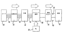
図4は、1つの実施例の荷重支持部材を製造する方法を示す概要図である。コードサプライ50はコード42を供給する。位置決め装置52はコード42を所望の配列に並べるので、コードは荷重支持部材40の長手方向軸に対して平行に伸長する。引張装置54はジャケット施工工程でコード42にかかる張力を制御する。ジャケット施工ステーション56はコード42上にジャケット材料を施すのに適するモールド成形装置またはその他の装置を含むのが好ましい。サプライ58は選択された材料を従来の方法でジャケット施工ステーション56へ提供する。ジャケット材料は加圧モールド成形、押出成形またはその他の方法でコード42上に施される。この実施例で製造されたアセンブリは仕上げステーション60で仕上げ処理される。図示されたこの実施例では、仕上げステーションはジャケットから少なくとも1つの表面層の少なくとも一部を除去するための装置を少なくとも1つ含む。
FIG. 4 is a schematic diagram illustrating a method of manufacturing the load support member of one embodiment. The
図5は、本発明の実施態様で使用される、ジャケット44の表面46からアミドリッチな層を少なくとも部分的に除去する装置の概略図である。図5の実施例では、研磨パッド65が粗い表面66を有し、これが仕上げステーション60の機械に支持されているので、表面66がジャケット44の表面46に少なくとも部分的に食い込む。1つの実施例では、可動部が研磨装置65を速やかに円を描くように動かすかまたは往復するように動かすことでジャケット44が研磨され、表面46から層が除去される。
FIG. 5 is a schematic diagram of an apparatus for at least partially removing an amide-rich layer from the
図6は、サンドペーパーのような研磨シート67が仕上げステーション60に適切に支持されて表面46と少なくとも部分的に接触し、表面46から材料を所望量だけ除去する別の実施例の概略図である。
FIG. 6 is a schematic diagram of another embodiment in which an
図7は、表面46から材料を除去するための別の装置を示す概略図である。この実施例では、バフ研磨パッド68が適切な方法で支持され表面を少なくとも部分的にこすりとり、適度な粗さになるまで表面をバフ研磨する。
FIG. 7 is a schematic diagram illustrating another apparatus for removing material from
図9は、表面46を破壊するのに有用なローラー63を示す。この実施例には、表面を破壊し表面46の対応する位置に純粋ポリウレタンを露出させるための突起部64が存在する。1つの実施例では、ローラー63は表面46から材料を除去せず、材料を移動させるかまたは変性させるにすぎない。弾性ジャケットが押出成形されて熱いうちに、表面構造を有するローラーまたはホイールを使用して表面層を破壊することができる。別の方法では、熱したローラーまたは外部熱源を利用して、押出成形から時間を置いて冷えた熱可塑性ジャケットの表面を変性させる。この方法の原理は、ワックス表面層を破壊して基本となるエラストマー特性をプリントスルーさせるというものである。
FIG. 9 shows a
表面46から材料を機械的に除去するのに必要な1つまたは複数の特定の装置は、用途に応じてジャケットおよび表面構造を形成するために選択された特定材料に従って変更することができる。さらに、除去工程は、例えば材料を扱いやすいように、乾燥していても湿度を有していてもよい。本明細書の恩恵を受ける当業者は、ここに記載されている装置かまたは同様の機能を有する別の装置を1つ以上組合せるなど、状況に応じて何が最善かを認識しているであろう。
The particular device or devices required to mechanically remove material from the
図5〜7および図9が機械的な除去技術について説明したのに対し、別の実施例の仕上げステーション60は化学薬品をベースとする除去工程を利用する。1つの実施例では、塗布装置70が例えば2−ブトキシエタノールと水との混合物のような薬品洗浄液を表面46の少なくとも一部に塗布し、表面46上の材料を部分的に腐食させ、薬品洗浄液を例えば水ですすぎ落とすとすぐに純粋ポリウレタンの露出した表面が得られる。他の実施例では、化学エッチング技術を表面46の少なくとも一部に実施する。本明細書の恩恵を受ける当業者は、特定状況で求められる要求事項に応じて、表面の少なくとも一部に所望量の純粋ポリウレタンを得るのに適した化学薬品および実施時間を選択できるであろう。
While FIGS. 5-7 and 9 describe the mechanical removal technique, another embodiment of the finishing
1つの実施例では、仕上げステーション60はまた、成形装置、寸法検査装置、および硬化用冷水浴を含み、この硬化用冷水浴は、ジャケット材料およびこのジャケット材料中のコードを好適な温度まで冷却する。仕上げステーションの成形装置は、所望の外形(すなわち長方形の横断面)が得られるようにジャケットへ力を加える硬質構造体を含むのが好ましい。例えばレーザー三角測量装置として知られるような検査装置は、所望の形状寸法が得られたかどうかを測定する。
In one embodiment, the finishing
得られた荷重支持部材40は次に装置62で保管されるのが好ましく、例えばエレベータシステムに取り付ける際に様々な場所へ運搬できるようスプールに巻かれている。荷重支持部材40は特定の長さに予め切断されてもよく、あるいは取り付けに携わる技術者が特定用途に適する量のベルト材料を選択できるように長めにしておいてもよい。
The resulting
上記記載は制限を目的とするのでは全くなく、例示を意図するものである。開示された実施例の変更および修正を行うことが、本発明の本質から外れるものではないことは当業者に明らかである。本発明に与えられる法的な保護の範囲は、以下の請求項を熟読することでのみ明らかにできる。 The above description is not intended to be limiting in any way, but is intended to be exemplary. It will be apparent to those skilled in the art that changes and modifications to the disclosed embodiments do not depart from the essence of the invention. The scope of legal protection given to this invention can only be determined by reading the following claims.
Claims (20)
前記材料を少なくとも部分的に除去する工程が、前記ポリマージャケットの幅の大部分に亘って第2の摩擦特性を有する表面層の少なくとも一部分を除去することにより、前記内側層の少なくとも一部を少なくとも部分的に露出させることを含み、露出した内側層が純粋ポリウレタンを含むことを特徴とする請求項1に記載のエレベーターシステムに使用する荷重支持部材の製造方法。The polymer jacket comprises an inner layer having a first friction characteristic and a surface layer having a second friction characteristic different from the first friction characteristic;
At least partially removing the material comprises at least removing at least a portion of the inner layer by removing at least a portion of the surface layer having a second friction characteristic over a majority of the width of the polymer jacket. The method for manufacturing a load bearing member for use in an elevator system according to claim 1, comprising partially exposing, wherein the exposed inner layer comprises pure polyurethane.
前記材料を少なくとも部分的に除去する工程が、前記内側層の少なくとも一部を少なくとも部分的に露出させることを特徴とする請求項9に記載のエレベーターシステムに使用する荷重支持部材。The polymer jacket comprises an inner layer having a first friction characteristic and a surface layer having a second friction characteristic different from the first friction characteristic;
The load supporting member for use in an elevator system according to claim 9, wherein the step of at least partially removing the material at least partially exposes at least a portion of the inner layer.
前記少なくとも1つの引張部材を概ね覆うようにポリマージャケットを施し、このポリマージャケットはアミドリッチ表面層を形成し、
前記ポリマージャケットの所望のトラクション特性を得るために、前記アミドリッチ表面層を少なくとも部分的に除去して表面に亘って純粋ポリウレタンを露出させることを含むことを特徴とするエレベーターシステムに使用する荷重支持部材の製造方法。Providing at least one tension member;
Applying a polymer jacket generally covering the at least one tensile member, the polymer jacket forming an amide-rich surface layer;
Load bearing for use in an elevator system comprising at least partially removing the amide rich surface layer to expose pure polyurethane over the surface to obtain the desired traction characteristics of the polymer jacket Manufacturing method of member.
Applications Claiming Priority (1)
| Application Number | Priority Date | Filing Date | Title |
|---|---|---|---|
| PCT/US2005/004257 WO2006085881A1 (en) | 2005-02-09 | 2005-02-09 | Elevator load bearing member having a jacket with at least one traction-enhancing exterior surface |
Publications (2)
| Publication Number | Publication Date |
|---|---|
| JP2008529927A JP2008529927A (en) | 2008-08-07 |
| JP5160901B2 true JP5160901B2 (en) | 2013-03-13 |
Family
ID=36793344
Family Applications (1)
| Application Number | Title | Priority Date | Filing Date |
|---|---|---|---|
| JP2007555063A Active JP5160901B2 (en) | 2005-02-09 | 2005-02-09 | Elevator load bearing member with jacket having at least one outer surface to increase traction capability |
Country Status (9)
| Country | Link |
|---|---|
| US (2) | US7883634B2 (en) |
| EP (2) | EP1851071B1 (en) |
| JP (1) | JP5160901B2 (en) |
| CN (1) | CN101115631B (en) |
| BR (1) | BRPI0520025B1 (en) |
| ES (1) | ES2641242T3 (en) |
| HK (1) | HK1117111A1 (en) |
| RU (1) | RU2487075C2 (en) |
| WO (1) | WO2006085881A1 (en) |
Families Citing this family (18)
| Publication number | Priority date | Publication date | Assignee | Title |
|---|---|---|---|---|
| DK1555234T3 (en) * | 2004-01-06 | 2006-08-21 | Inventio Ag | Elevator |
| US9546447B2 (en) * | 2005-10-27 | 2017-01-17 | Otis Elevator Company | Elevator load bearing assembly having a jacket with multiple polymer compositions |
| EP2349163B1 (en) * | 2008-09-11 | 2016-04-13 | Tollos Inc. | Infection control lifting strap |
| US10010468B2 (en) | 2008-09-11 | 2018-07-03 | 1073849 Ontario Limited | Infection control strap and patient lifting system |
| CN102264623B (en) * | 2008-12-22 | 2013-09-04 | 因温特奥股份公司 | Elevator support means, manufacturing method for said support means and elevator system comprising said elevator support means |
| EP2665671A4 (en) * | 2011-01-21 | 2016-03-16 | Otis Elevator Co | System and method for reducing belt noise |
| CH705350A1 (en) * | 2011-08-09 | 2013-02-15 | Brugg Drahtseil Ag | Traction member with a force transfer surface with different frictional properties. |
| CH706170A2 (en) * | 2012-02-23 | 2013-08-30 | Cortex Huembelin Ag | High-security cable. |
| EP2850027B1 (en) * | 2012-05-16 | 2020-10-14 | Otis Elevator Company | Coated sheave |
| DE112012006381T5 (en) * | 2012-05-16 | 2015-01-29 | Otis Elevator Company | Pulley for an elevator system |
| DK2777674T3 (en) | 2013-03-14 | 2016-05-30 | Liko Res And Dev Ab | Protective case for lifting strap in ceiling lift |
| EP3071503B1 (en) * | 2013-11-22 | 2020-08-12 | Otis Elevator Company | Resurfacing of belt for elevator system |
| EP3009390B1 (en) * | 2014-10-16 | 2018-12-05 | KONE Corporation | Method for manufacturing a hoisting rope, hoisting rope and elevator using the same |
| ES2741353T3 (en) * | 2015-09-14 | 2020-02-10 | Otis Elevator Co | Repair in operation of elevator belt |
| WO2017155943A1 (en) * | 2016-03-09 | 2017-09-14 | Otis Elevator Company | Reinforced fabric elevator belt with improved internal wear resistance |
| US10767077B2 (en) * | 2017-01-30 | 2020-09-08 | Otis Elevator Company | Load-bearing member surface treatment |
| US11459209B2 (en) | 2017-11-10 | 2022-10-04 | Otis Elevator Company | Light weight load bearing member for elevator system |
| US11655120B2 (en) * | 2019-06-28 | 2023-05-23 | Otis Elevator Company | Elevator load bearing member including a unidirectional weave |
Family Cites Families (19)
| Publication number | Priority date | Publication date | Assignee | Title |
|---|---|---|---|---|
| DE950602C (en) * | 1953-05-23 | 1956-10-11 | Phoenix Gummiwerke Ag | Process for increasing the coefficient of friction in objects made of polyurethane plastics made of linear, purely aliphatic polyesters |
| DE1048101B (en) * | 1956-03-20 | 1958-12-31 | Wilhelm Herm Mueller & Co K G | Flat belts, in particular drive belts, made of plastic with a roughened friction layer |
| DE3231144A1 (en) * | 1982-08-21 | 1984-02-23 | Basf Ag, 6700 Ludwigshafen | METHOD FOR PRODUCING PRINTING FORMS WITH PLASTIC PRINT LAYERS |
| JP2740339B2 (en) * | 1990-07-06 | 1998-04-15 | 大日精化工業株式会社 | ink ribbon |
| CZ282660B6 (en) * | 1994-03-02 | 1997-08-13 | Inventio Ag | Bearer rope of lifting and transport facilities |
| US6401871B2 (en) * | 1998-02-26 | 2002-06-11 | Otis Elevator Company | Tension member for an elevator |
| US6256841B1 (en) * | 1998-12-31 | 2001-07-10 | Otis Elevator Company | Wedge clamp type termination for elevator tension member |
| US6245822B1 (en) * | 1998-04-27 | 2001-06-12 | Matsushita Electric Industrial Co. Ltd. | Method and apparatus for decomposition treating article having cured thermosetting resin |
| US6371448B1 (en) * | 1999-10-29 | 2002-04-16 | Inventio Ag | Rope drive element for driving synthetic fiber ropes |
| US6488123B2 (en) | 2001-02-12 | 2002-12-03 | Otis Elevator Company | Directional uniformity of flat tension members for elevators |
| JP4190165B2 (en) * | 2001-03-02 | 2008-12-03 | 株式会社リコー | Photoconductor traveling device, image forming apparatus, and process cartridge |
| JP5244275B2 (en) * | 2001-04-26 | 2013-07-24 | オーチス エレベータ カンパニー | Elevator apparatus tension member and method of forming tension member |
| CA2363480A1 (en) * | 2001-05-14 | 2002-11-14 | Ronald F. Ryde | Grooved flexible conveyor belt |
| US6816691B2 (en) * | 2001-05-21 | 2004-11-09 | Ricoh Company | Apparatus having endless belt with roughened guide |
| EP1402198B1 (en) * | 2001-06-21 | 2006-05-31 | Habasit AG | Monolithic belts containing ethylene-alpha-olefin copolymers |
| US20030024770A1 (en) | 2001-08-03 | 2003-02-06 | O'donnell Hugh James | Elevator belt assembly with waxless coating |
| US8444515B2 (en) * | 2001-11-13 | 2013-05-21 | Otis Elevator Company | Elevator belt assembly with noise and vibration reducing grooveless jacket arrangement |
| ATE448169T1 (en) * | 2003-02-07 | 2009-11-15 | Otis Elevator Co | WINDER BELT WITH NOISE-DAMPENING GROOVE ARRANGEMENT |
| EP1725375B2 (en) * | 2004-03-15 | 2018-01-24 | Otis Elevator Company | Method of making an ELEVATOR LOAD BEARING MEMBER HAVING A JACKET WITH AT LEAST ONE ROUGH EXTERIOR SURFACE |
-
2005
- 2005-02-09 JP JP2007555063A patent/JP5160901B2/en active Active
- 2005-02-09 BR BRPI0520025-3A patent/BRPI0520025B1/en active IP Right Grant
- 2005-02-09 US US11/814,568 patent/US7883634B2/en active Active
- 2005-02-09 CN CN2005800478953A patent/CN101115631B/en active Active
- 2005-02-09 ES ES05713290.4T patent/ES2641242T3/en active Active
- 2005-02-09 WO PCT/US2005/004257 patent/WO2006085881A1/en active Application Filing
- 2005-02-09 EP EP05713290.4A patent/EP1851071B1/en active Active
- 2005-02-09 RU RU2007133738/11A patent/RU2487075C2/en not_active Application Discontinuation
- 2005-02-09 EP EP12162682A patent/EP2484622A1/en not_active Ceased
-
2008
- 2008-07-18 HK HK08107987.2A patent/HK1117111A1/en not_active IP Right Cessation
-
2010
- 2010-12-29 US US12/980,390 patent/US20110108371A1/en not_active Abandoned
Also Published As
| Publication number | Publication date |
|---|---|
| BRPI0520025A2 (en) | 2009-08-18 |
| ES2641242T3 (en) | 2017-11-08 |
| RU2007133738A (en) | 2009-03-20 |
| BRPI0520025B1 (en) | 2018-04-03 |
| CN101115631B (en) | 2011-06-08 |
| HK1117111A1 (en) | 2009-01-09 |
| US20110108371A1 (en) | 2011-05-12 |
| JP2008529927A (en) | 2008-08-07 |
| RU2487075C2 (en) | 2013-07-10 |
| EP1851071A4 (en) | 2010-02-17 |
| WO2006085881A1 (en) | 2006-08-17 |
| EP2484622A1 (en) | 2012-08-08 |
| CN101115631A (en) | 2008-01-30 |
| US20080156592A1 (en) | 2008-07-03 |
| US7883634B2 (en) | 2011-02-08 |
| EP1851071B1 (en) | 2017-09-13 |
| EP1851071A1 (en) | 2007-11-07 |
Similar Documents
| Publication | Publication Date | Title |
|---|---|---|
| JP5160901B2 (en) | Elevator load bearing member with jacket having at least one outer surface to increase traction capability | |
| CN100581727C (en) | Elevator load bearing element having sheath with at least one rough external surface | |
| JP4903799B2 (en) | Method for manufacturing load support member for elevator system | |
| US20130237358A1 (en) | Elevator belt assembly with noise and vibration reducing grooveless jacket arrangement | |
| KR100903832B1 (en) | Elevator load bearing member having a jacket with at least one traction-enhancing exterior surface | |
| JP2007210761A (en) | Elevator device | |
| JP4523364B2 (en) | elevator | |
| KR100842663B1 (en) | Method of Making Load Bearing Member for Use in Elevator System and Load Bearing Member for Use in Elevator System | |
| KR20080044361A (en) | Method of making load bearing member for use in elevator system and load bearing member for use in elevator system | |
| RU2338681C2 (en) | Method for producing lift system load-carrying element (versions) and this element (versions) | |
| JP2007210795A (en) | Elevator device | |
| JP2007210796A (en) | Elevator device |
Legal Events
| Date | Code | Title | Description |
|---|---|---|---|
| A131 | Notification of reasons for refusal |
Free format text: JAPANESE INTERMEDIATE CODE: A131 Effective date: 20110301 |
|
| A601 | Written request for extension of time |
Free format text: JAPANESE INTERMEDIATE CODE: A601 Effective date: 20110531 |
|
| RD02 | Notification of acceptance of power of attorney |
Free format text: JAPANESE INTERMEDIATE CODE: A7422 Effective date: 20110531 |
|
| RD04 | Notification of resignation of power of attorney |
Free format text: JAPANESE INTERMEDIATE CODE: A7424 Effective date: 20110531 |
|
| A602 | Written permission of extension of time |
Free format text: JAPANESE INTERMEDIATE CODE: A602 Effective date: 20110623 |
|
| A601 | Written request for extension of time |
Free format text: JAPANESE INTERMEDIATE CODE: A601 Effective date: 20110701 |
|
| A602 | Written permission of extension of time |
Free format text: JAPANESE INTERMEDIATE CODE: A602 Effective date: 20110708 |
|
| A521 | Request for written amendment filed |
Free format text: JAPANESE INTERMEDIATE CODE: A523 Effective date: 20110729 |
|
| A131 | Notification of reasons for refusal |
Free format text: JAPANESE INTERMEDIATE CODE: A131 Effective date: 20120327 |
|
| A521 | Request for written amendment filed |
Free format text: JAPANESE INTERMEDIATE CODE: A523 Effective date: 20120627 |
|
| TRDD | Decision of grant or rejection written | ||
| A01 | Written decision to grant a patent or to grant a registration (utility model) |
Free format text: JAPANESE INTERMEDIATE CODE: A01 Effective date: 20121204 |
|
| A61 | First payment of annual fees (during grant procedure) |
Free format text: JAPANESE INTERMEDIATE CODE: A61 Effective date: 20121213 |
|
| R150 | Certificate of patent or registration of utility model |
Ref document number: 5160901 Country of ref document: JP Free format text: JAPANESE INTERMEDIATE CODE: R150 Free format text: JAPANESE INTERMEDIATE CODE: R150 |
|
| FPAY | Renewal fee payment (event date is renewal date of database) |
Free format text: PAYMENT UNTIL: 20151221 Year of fee payment: 3 |
|
| R250 | Receipt of annual fees |
Free format text: JAPANESE INTERMEDIATE CODE: R250 |
|
| R250 | Receipt of annual fees |
Free format text: JAPANESE INTERMEDIATE CODE: R250 |
|
| R250 | Receipt of annual fees |
Free format text: JAPANESE INTERMEDIATE CODE: R250 |
|
| R250 | Receipt of annual fees |
Free format text: JAPANESE INTERMEDIATE CODE: R250 |
|
| R250 | Receipt of annual fees |
Free format text: JAPANESE INTERMEDIATE CODE: R250 |
|
| R250 | Receipt of annual fees |
Free format text: JAPANESE INTERMEDIATE CODE: R250 |
|
| R250 | Receipt of annual fees |
Free format text: JAPANESE INTERMEDIATE CODE: R250 |
|
| R250 | Receipt of annual fees |
Free format text: JAPANESE INTERMEDIATE CODE: R250 |
|
| R250 | Receipt of annual fees |
Free format text: JAPANESE INTERMEDIATE CODE: R250 |