JP5160686B2 - Method for aligning loaded bags in a vacuum chamber - Google Patents
Method for aligning loaded bags in a vacuum chamber Download PDFInfo
- Publication number
- JP5160686B2 JP5160686B2 JP2011511624A JP2011511624A JP5160686B2 JP 5160686 B2 JP5160686 B2 JP 5160686B2 JP 2011511624 A JP2011511624 A JP 2011511624A JP 2011511624 A JP2011511624 A JP 2011511624A JP 5160686 B2 JP5160686 B2 JP 5160686B2
- Authority
- JP
- Japan
- Prior art keywords
- bag
- loaded
- conveyor
- vacuum chamber
- vacuum
- Prior art date
- Legal status (The legal status is an assumption and is not a legal conclusion. Google has not performed a legal analysis and makes no representation as to the accuracy of the status listed.)
- Expired - Fee Related
Links
Images


Classifications
-
- G—PHYSICS
- G01—MEASURING; TESTING
- G01B—MEASURING LENGTH, THICKNESS OR SIMILAR LINEAR DIMENSIONS; MEASURING ANGLES; MEASURING AREAS; MEASURING IRREGULARITIES OF SURFACES OR CONTOURS
- G01B11/00—Measuring arrangements characterised by the use of optical techniques
- G01B11/02—Measuring arrangements characterised by the use of optical techniques for measuring length, width or thickness
- G01B11/04—Measuring arrangements characterised by the use of optical techniques for measuring length, width or thickness specially adapted for measuring length or width of objects while moving
-
- B—PERFORMING OPERATIONS; TRANSPORTING
- B65—CONVEYING; PACKING; STORING; HANDLING THIN OR FILAMENTARY MATERIAL
- B65B—MACHINES, APPARATUS OR DEVICES FOR, OR METHODS OF, PACKAGING ARTICLES OR MATERIALS; UNPACKING
- B65B31/00—Packaging articles or materials under special atmospheric or gaseous conditions; Adding propellants to aerosol containers
- B65B31/02—Filling, closing, or filling and closing, containers or wrappers in chambers maintained under vacuum or superatmospheric pressure or containing a special atmosphere, e.g. of inert gas
- B65B31/024—Filling, closing, or filling and closing, containers or wrappers in chambers maintained under vacuum or superatmospheric pressure or containing a special atmosphere, e.g. of inert gas specially adapted for wrappers or bags
-
- B—PERFORMING OPERATIONS; TRANSPORTING
- B65—CONVEYING; PACKING; STORING; HANDLING THIN OR FILAMENTARY MATERIAL
- B65B—MACHINES, APPARATUS OR DEVICES FOR, OR METHODS OF, PACKAGING ARTICLES OR MATERIALS; UNPACKING
- B65B57/00—Automatic control, checking, warning, or safety devices
Abstract
Description
本発明は、装填された袋を真空チャンバ内に位置合わせするための方法に関する。 The present invention relates to a method for aligning a loaded bag within a vacuum chamber.
ヒートシール可能なプラスチック袋における真空包装は、肉およびチーズ等の食品をパッケージする従来的な方法である。真空包装は、典型的には、袋の口を有するヒートシール可能プラスチック袋に食料品を置くことと、次に袋の口を介して袋から空気を抜くことと、包含される食料品の近くで袋を潰すことを含む。袋は次に、空気抜きされた状態でヒートシールされ、よって食料品は概して空気のない環境に入れられた状態になる。袋は熱収縮性の袋である場合が多く、よってヒートシールステップの後は食料品の周囲での袋の収縮を誘導するために熱水または熱風収縮トンネルへと前進させられる。 Vacuum packaging in heat-sealable plastic bags is a conventional method for packaging food products such as meat and cheese. Vacuum packaging typically involves placing food items in a heat-sealable plastic bag having a bag mouth, and then deflating the bag through the bag mouth, near the food items contained. Including crushing the bag. The bag is then heat sealed in a deflated state so that the food product is generally in an airless environment. The bag is often a heat-shrinkable bag and is therefore advanced after the heat sealing step into hot water or hot air shrink tunnels to induce shrinkage of the bag around the food product.
知られているタイプの真空包装機は、シールされていない装填された袋を受け入れるように配置されかつ装填された袋に真空シール作業を実行するように動作可能な真空チャンバを含む。典型的には、装填された袋は、熱収縮性フィルムにより製造される袋内に配列された肉の切り身等の製品を入れている。装填された袋を真空チャンバへ供給して真空チャンバを閉止した後、真空シール作業は、典型的には真空引きと、真空引きされた袋の口をシールすることと、チャンバ内へ空気を再び導入することを含む。次にチャンバは開けられ、真空チャンバから袋が取り出される。アプリケーションによっては、パッケージは、製品の周りでパッケージを収縮させるために熱収縮ユニットへ運搬されてもよい。 A known type of vacuum packaging machine includes a vacuum chamber arranged to receive an unsealed loaded bag and operable to perform a vacuum sealing operation on the loaded bag. Typically, a loaded bag contains products such as meat fillets arranged in a bag made of heat shrinkable film. After supplying the loaded bag to the vacuum chamber and closing the vacuum chamber, the vacuum sealing operation typically involves evacuation, sealing the evacuated bag mouth, and air again into the chamber. Including introducing. The chamber is then opened and the bag is removed from the vacuum chamber. Depending on the application, the package may be transported to a heat shrink unit to shrink the package around the product.
ロータリ真空包装機は知られており、これは、一連の真空チャンバとチェーン駆動式の製品プラテンとを含む。マシンの動作において、プラテンは装填位置から真空引き/シール/通気ステージを経て取り出し位置へと移動し、最終的に装填位置へ戻る。典型例は、株式会社古川製作所により開発されかつ米国特許第3,958,391号明細書(クジュウブ)、第4,580,393号明細書(フルカワ)および第4,640,081号明細書(カワグチ、外)に開示されている包装機および包装機システムである。これらの特許は全て、参照によりその全体が本明細書に組み込まれる。 Rotary vacuum packaging machines are known and include a series of vacuum chambers and a chain driven product platen. In machine operation, the platen moves from the loading position through the evacuation / sealing / venting stage to the removal position and finally returns to the loading position. Typical examples are those developed by Furukawa Seisakusho Co., Ltd. and U.S. Pat. Nos. 3,958,391 (Kujubu), 4,580,393 (Furukawa), and 4,640,081 ( A packaging machine and a packaging machine system disclosed in Kawaguchi, et al. All of these patents are incorporated herein by reference in their entirety.
米国特許第7,296,390号明細書(コウケ、外)の特許は参照により本明細書にその全体が組み込まれるが、各々が少なくとも1つのシールされていない装填された袋を受け入れるように配置されかつ独立した真空シール作業を実行するように動作可能である複数の真空チャンバを含む真空包装機を開示していて、各真空チャンバは、チャンバを介する個々の装填された袋の移動方向によって画定される長手方向を有し、各チャンバは内部に、長手方向を横切って延びるヒートシールアッセンブリを有する。送込みコンベアは、シールされていない装填された袋を真空チャンバへ供給するために設けられ、よって、シールされていない装填された袋の後(上流側)の端は、ヒートシールアッセンブリまたはその一部の上に延びる。各真空チャンバは個々のベッドおよび独立して移動可能なフードを有し、これらのベッドは同期して垂直動作が可能である。真空包装機は、適切な袋詰め機またはラッピング機と組み合わせて使用されることが可能である。 The patents of US Pat. No. 7,296,390 (Koke, et al.) Are hereby incorporated by reference in their entirety, but each is arranged to receive at least one unsealed loaded bag. And a vacuum packaging machine including a plurality of vacuum chambers operable to perform independent vacuum sealing operations, each vacuum chamber being defined by a direction of travel of an individual loaded bag through the chamber Each chamber has a heat seal assembly extending across the longitudinal direction therein. The infeed conveyor is provided to supply unsealed loaded bags to the vacuum chamber, so that the back (upstream) end of unsealed loaded bags is the heat seal assembly or one of its Extending over the part. Each vacuum chamber has an individual bed and an independently movable hood, and these beds can be operated vertically in synchronization. The vacuum packaging machine can be used in combination with a suitable bagging or wrapping machine.
上記米国特許第7,296,390号明細書に開示されているシステムは、ニュージーランドにおいて、袋詰めされた肉製品をパッケージするためのTASVAC(TM)真空包装システムとして商品化されている。開示されているシステムでは、ヒートシールして袋の口を閉じた後に約2インチ(50.8ミリメートル)以下の袋尾部(袋詰め製品の後縁とヒートシールとの間に位置決めされるシールされた袋の部分)が袋上に残るように、各袋詰め製品の後(即ち、上流側)縁を配置することが有益である。これより長い、例えば2インチ(50.8ミリメートル)より長い袋尾部は、過剰な量の熱可塑性材料を使用して袋を製造することに繋がり、また美観もより短い袋尾部を有する袋より劣る。袋尾部としては、1インチ(25.4ミリメートル)など、約1.5インチ(約37.6ミリメートル)未満が袋上に残されることが有益である。また、形が不規則な肉の切り身、具体的には高い垂直形状を有するものを収容するに足る袋尾部を有することも重要である。言い換えれば、ヒートアッセンブリの位置に対して各製品の後縁を位置合わせするための許容誤差は、1インチ(25.4ミリメートル)など、最大プラスマイナス1.5インチ(約37.6ミリメートル)であることが有益である。 The system disclosed in U.S. Patent No. 7,296,390 is commercialized in New Zealand as a TASVAC (TM) vacuum packaging system for packaging packaged meat products. In the disclosed system, the bag tail (less than about 2 inches (50.8 millimeters)) after heat sealing and closing the bag mouth (a seal positioned between the trailing edge of the bag product and the heat seal). It is beneficial to position the trailing (ie upstream) edge of each bag product so that a portion of the bag remains on the bag. Bag tails longer than this, for example longer than 2 inches (50.8 millimeters), lead to the manufacture of bags using excessive amounts of thermoplastic material and are also inferior to bags with shorter bag tails. . Beneficially, less than about 1.5 inches (about 37.6 millimeters), such as 1 inch (25.4 millimeters), is left on the bag. It is also important to have a bag tail sufficient to accommodate irregularly shaped meat fillets, specifically those having a high vertical shape. In other words, the tolerance for aligning the trailing edge of each product relative to the position of the heat assembly is up to plus or minus 1.5 inches (about 37.6 millimeters), such as 1 inch (25.4 millimeters). It is beneficial to be.
従って、TASVAC(TM)システムの場合、例えば食肉加工場において送込みコンベア上で列に並べられて前進されている一連の袋詰めされた肉製品をパッケージする際には、下流側の真空チャンバに対するこれらの位置を、装填された袋が真空チャンバへかつ真空チャンバの内側へ前進するにつれて各袋がヒートシールアッセンブリと正しく位置合わせされ得るように決定することが望ましい。 Thus, in the case of a TASVAC (TM) system, for example, when packaging a series of packaged meat products that are being advanced in a row on a feed conveyor in a slaughterhouse, It is desirable to determine these positions so that each bag can be properly aligned with the heat seal assembly as the loaded bags are advanced into the vacuum chamber and into the vacuum chamber.
一般的な送込みコンベア上の真空チャンバの上流側に位置合わせされる容量センサは、袋詰め製品が所定の真空チャンバ内へ前進する前にシールされていない袋内に位置合わせされる製品の後縁の位置を決定することにおいては信頼性がないことがテストされかつ証明されている。というのも、部分的には、容量センサがパッケージされつつある肉製品内の湿度の検出に依存することにあるからである。様々な肉の切り身が熱可塑性の袋内にパッケージされている典型的な食肉加工場では、一般に肉のコンベア上に水または血液の形で湿気が存在する。従って、容量センサの使用は肉製品の存在の「誤検出」示度を与えることがあり、よって下流側真空チャンバのヒートシールアッセンブリに対する各袋詰め製品の適正な前進および位置合わせは困難であって信頼性がない。さらに、容量センサが有するセンサ高度の最大範囲は、典型的には約40ミリメートルである。 A volume sensor that is aligned upstream of the vacuum chamber on a typical infeed conveyor is after the product that is aligned in an unsealed bag before the packaged product is advanced into a given vacuum chamber. It has been tested and proven to be unreliable in determining the edge location. This is because, in part, the capacitive sensor relies on the detection of humidity in the meat product being packaged. In a typical slaughterhouse where various meat fillets are packaged in thermoplastic bags, moisture is typically present in the form of water or blood on the meat conveyor. Thus, the use of a capacitive sensor can provide a “false positive” indication of the presence of meat products, and therefore, proper advancement and alignment of each packaged product with respect to the heat seal assembly of the downstream vacuum chamber is difficult. There is no reliability. Further, the maximum range of sensor height that a capacitive sensor has is typically about 40 millimeters.
上述の装置およびプロセスに使用される製品センサは、製品が送込みコンベアに沿って前進するにつれて、または送込みコンベア上に位置合わせされるにつれて製品を識別すること、即ち製品の後縁を識別することができるものであるべきである。センサは、識別を薄切りの子牛肉から厚切りの新鮮な赤身肉またはチーズの塊にまで及ぶ範囲の製品に対して行うことができるものであるべきであり、かつ識別を透明な印刷されかつ着色された袋を通して行うことができるものであるべきである。これらの切り身の多くは、形状および輪郭が奇妙なものになる。センサは、食肉およびチーズ包装場における過酷な生産環境に耐えることができるものでもあるべきである。製品検出システムの全体コストも、同時に考慮されなければならない。 The product sensor used in the apparatus and process described above identifies the product as the product advances along the feed conveyor or is aligned on the feed conveyor, i.e. identifies the trailing edge of the product. It should be possible. The sensor should be capable of identification on products ranging from sliced veal to thick sliced fresh red meat or cheese chunks, and the identification should be transparent printed and colored. Should be able to be done through the sachet. Many of these fillets have strange shapes and contours. The sensor should also be able to withstand the harsh production environment in meat and cheese packaging. The overall cost of the product detection system must be considered at the same time.
本発明は、真空チャンバ内にシールされていない装填された袋を位置合わせするための方法を提供する。本発明は、装填された袋が真空チャンバ内にある間に、内部に不規則形状の肉製品等の製品を有するポリマー袋の上流側の端を一貫して適切な長さの袋尾部を設けるようにしてシールすることを可能にする。 The present invention provides a method for aligning a loaded bag that is not sealed in a vacuum chamber. The present invention consistently provides an appropriate length bag tail at the upstream end of a polymer bag having a product such as an irregularly shaped meat product therein while the loaded bag is in a vacuum chamber. In this way.
第1の態様において、装填された袋を真空チャンバ内に位置合わせする方法は、
柔軟なポリマー袋内に製品を置くことによって柔軟なポリマー袋を装填することであって、バッグは赤外線を通す材料から製造され、かつポリマー袋は上流側の端に袋の口を有することと、
装填された袋を赤外線を通す送込みコンベア上へ置くことと、
装填された袋を送込みコンベア上で、コンベア上方に配置される赤外線カメラとコンベア下方に配置される発光ダイオードバンクとを含む検出装置へと前進させることと、
装填された袋内部の製品の後縁を検出するために、検出装置を使用して赤外線により装填された袋を通して発光ダイオードバンクを調査(interrogate)することと、
調査するステップから取得される情報をプログラマブルロジックコントローラへ送信することと、
調査された装填された袋を、調査ステップから取得される情報に基づいてある距離だけヒートシールアッセンブリを含む真空チャンバへと前進させることと、
袋の口を閉じるために、装填された袋をヒートシールアッセンブリでヒートシールすることとを含む。
In a first aspect, a method for aligning a loaded bag within a vacuum chamber comprises:
Loading the flexible polymer bag by placing the product in the flexible polymer bag, wherein the bag is made from an infrared-permeable material, and the polymer bag has a bag mouth at the upstream end;
Placing the loaded bag on an infeed conveyor that passes infrared;
Advancing the loaded bag on a feed conveyor to a detection device including an infrared camera located above the conveyor and a light emitting diode bank located below the conveyor;
Interrogating the light-emitting diode bank through the bag loaded with infrared using a detector to detect the trailing edge of the product inside the loaded bag;
Sending information obtained from the investigating step to the programmable logic controller;
Advancing the inspected loaded bag by a distance based on information obtained from the inspecting step into a vacuum chamber containing a heat seal assembly;
Heat sealing the loaded bag with a heat seal assembly to close the bag mouth.
ある実施形態において、上述の方法は、製品のヒートシールと後縁との距離が1.5インチ未満であるように装填された袋をヒートシールすることを含む。 In certain embodiments, the above-described method includes heat sealing a loaded bag such that the distance between the product heat seal and the trailing edge is less than 1.5 inches.
別の実施形態において、上述の方法は、製品のヒートシールと後縁との距離が1インチ未満であるように装填された袋をヒートシールすることを含む。 In another embodiment, the above-described method includes heat sealing a bag loaded such that the distance between the product heat seal and the trailing edge is less than 1 inch.
別の実施形態において、装填された袋を真空チャンバ内に位置合わせする上述の方法は装填された袋を真空シールする方法と組み合わせて実行され、方法は、複数の真空チャンバを有する真空包装機を準備することであって、真空チャンバの各々はシールされていない装填された袋を受け入れるように配置されかつ装填された袋に真空シール作業を実行するように動作可能であり、各真空チャンバはチャンバを介する個々の装填された袋の移動経路によって画定される長手方向を有し、各真空チャンバは個々の装填された袋の袋の口を横断してヒートシールを形成するためのヒートシールアッセンブリを有し、ヒートシールは前記長手方向を横切って配置されることと、装填された袋の袋の口がヒートシールアッセンブリの一部を覆って位置決めされるように、シールされていない装填された袋を真空チャンバの一方へと送り込むことと、もう一方の真空チャンバにおいて装填された袋に真空シール作業を実行することを含む。 In another embodiment, the above-described method of aligning a loaded bag within a vacuum chamber is performed in combination with a method of vacuum sealing a loaded bag, the method comprising: a vacuum packaging machine having a plurality of vacuum chambers. Each of the vacuum chambers is arranged to receive an unsealed loaded bag and is operable to perform a vacuum sealing operation on the loaded bag, each vacuum chamber being a chamber Each vacuum chamber has a heat seal assembly for forming a heat seal across the mouth of the bag of the individual loaded bag. And the heat seal is positioned across the longitudinal direction and the bag mouth of the loaded bag covers a portion of the heat seal assembly. As fit includes that the loaded bag is not sealed feed into one of the vacuum chamber, to perform a vacuum sealing operation on the bags loaded in the other vacuum chamber.
別の実施形態において、装填された袋を真空チャンバ内に位置合わせする上述の方法は、柔軟なポリマー袋内に肉製品を入れるステップを含み、肉製品は不規則な形状を有する。 In another embodiment, the above-described method of aligning a loaded bag in a vacuum chamber includes placing the meat product in a flexible polymer bag, the meat product having an irregular shape.
次に、添付の図面を参照して本発明の実施形態について説明する。 Next, embodiments of the present invention will be described with reference to the accompanying drawings.
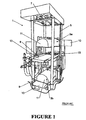
図1および図2を参照すると、本発明に関連して使用することに適する真空包装機の一実施形態が全体として参照数字1で示されている。真空包装機は垂直に重ねられた上側および下側の真空チャンバ3a、3bを含み、これらの支柱5間で垂直に移動できるように取り付けられる。支柱5の頂部には、真空チャンバ3a、3bのための駆動機構7が隣接して取り付けられる。
Referring to FIGS. 1 and 2, one embodiment of a vacuum packaging machine suitable for use in connection with the present invention is indicated generally by the reference numeral 1. The vacuum packaging machine includes upper and
電子制御システム8は包装機1の動作を制御し、かつユーザが制御システムをプログラムすることを可能にするキーパッド/モニタ10が備えられる。
The
各真空チャンバ3a、3bは、ベッド9と、チャンバフード11とを含む。これらのベッド9は支柱5間で同期して垂直移動できるように取り付けられ、かつ各チャンバフード11は個々のベッド9に相対して垂直に移動可能である。チャンバフード11は、例えば空気圧ラム、油圧ラムまたは機械駆動装置である任意の適切な動力デバイスを介して移動される。
Each
各真空チャンバは内部に、図3から図6までを参照して後述するシールアッセンブリ15を有する。各真空チャンバのベッド9は、パッケージされた製品をそれが真空シールされた後にチャンバから運び出すための内部コンベア13を含み、コンベア13の移動方向は真空チャンバの長手方向を画定する。
Each vacuum chamber has a
コンベア装置は、装填された袋を真空チャンバへ供給しかつこれを真空チャンバから取り出すために装備される。コンベア装置は、装填された袋を真空チャンバ内へ送り込むための送込みコンベア17を含む。シールに続いて包装機からシール済みの装填された袋を取り出すために、任意選択の送出しコンベア(図示しない)も装備される。
The conveyor device is equipped to supply the loaded bag to the vacuum chamber and remove it from the vacuum chamber. The conveyor device includes a
これらの真空チャンバは、上側のチャンバ3aが送込みおよび取り出しのために送込みコンベア17に隣接する下側の位置(図1および図2に示されている)と、下側のチャンバ3bのベッドが送込みおよび取り出しのために送込みコンベア17に隣接する上側の位置(図示しない)との間で共に移動可能である。これらの真空チャンバのうちの一方が送込み/取り出し位置にある間、もう一方のチャンバは、内部に入っている装填された袋に真空シール作業を実行するための動作位置にある。従って、上側の真空チャンバ3aの動作位置は送込みコンベアの高さより上であり、一方で下側の真空チャンバ3bの動作位置は送込みコンベアの高さより下である。
These vacuum chambers have a lower position (shown in FIGS. 1 and 2) adjacent to the
図3から図6までにおいて分かるように、各真空チャンバ内のシールアッセンブリ15は上側部分15aと下側部分15bとを含む。シールアッセンブリ15は、真空チャンバの長手方向へ、従ってチャンバを介して装填された袋の移動方向に対して横方向に延びる。これは、装填された袋が真空チャンバへシールされていない部分を後にして運ばれることを可能にし、このことはは、装填された袋が先行する袋詰め/ラッピングステーションから出る際の方向づけとなる。
As can be seen in FIGS. 3-6, the
シールアッセンブリの上側部分15aは、1対の上側スプレッダ19aと、ヒートシールアンビル21と、複数の穿孔ナイフ(図示しない)を有する穿刺デバイスと、一連のクランプピン25を有するクランプデバイス23とを含む。シールアッセンブリの下側部分15bは、1対の上側スプレッダ19aと相補的である1対の下側スプレッダ19bと、ヒートシールバー27と、下側のクランプバー29とを含む。アンビルは、ヒートシールバーがシールアッセンブリの上側部分15aに設けられた状態で、シールアッセンブリの下側部分15bに設けられる可能性もあることは認識されるであろう。
The
本実施形態における拡張動作は、以下の通りである。スプレッダ19a、19bは、ヒートシールに先立って装填された袋のシールされていない部分を把持して拡げるように動作可能である。図から明らかであるように、上側スプレッダ19aおよび下側スプレッダ19bは、互いに引き合わされるにつれて傾斜溝20aおよび傾斜溝を貫通して延びるピン20bにより外側へ移動する。これらのスプレッダは、米国特許第6,877,543号明細書(Stevens)に記載されているものと同様に機能する。上記特許は、参照によりその全体が本明細書に組み込まれる。
The expansion operation in this embodiment is as follows. The
クランプピン25および下側のクランプバー29(概してゴム等の弾性材料から製造される)は、パッケージのシールされていない部分を拡げられた形状に保持し、かつ穿刺できるように装填された袋に張力をかける。穿刺デバイスが起動されると、ナイフ(図示しない)がパッケージを穿孔する。穿刺デバイスは装填された袋に小さい開口を形成する。装填された袋を真空チャンバ内へ送り込む間、装填された袋の引きずられるシールされていない部分が真空チャンバフード11の閉止時にフードの端壁下でクランプされるように位置決めされることは実現可能な状況である。穿刺デバイスにより形成される開口は、こうした状況が発生しても装填された袋内の空気が抜かれることを確実にする。
The
ヒートシールアンビル21は、装填された袋のシールされていない部分を間にした状態でヒートシールバー27を押すように動作可能であり、ヒートシールバーに電流が印加されて装填された袋がシールされる。
The
図示されていないが、ヒートシールバー27と穿刺デバイスとの間には装填された袋を切断するための適切な切断デバイスが設けられる。切断デバイスの一例は鋸歯付きナイフであり、これは、装填された袋を剪断するために上から下へ移動するように配置される。
Although not shown, a suitable cutting device for cutting the loaded bag is provided between the
コンベア13のベルトは、シールアッセンブリの下側部分15bの下で真空チャンバのベッド9の外端を回って延びる。本目的のために、コンベアベルトの下面は、例えば伸縮性のある滑らかな表面である(従来の織布表面よりも)滑らかな表面を備え、よって真空チャンバはベルト上でシールを実行することができる。
The belt of the
装填された袋をシールアッセンブリの下側部分15b上へ送り込むために、ある実施形態では、送込みコンベア17は伸縮部分17aを有する。装填された袋を開放された真空チャンバ内へ送り込む間、伸縮部分17aはシールアッセンブリの下側部分15bの上へ延び、装填された袋の本体を真空チャンバのベッド9上のコンベア13へ落とすように動作される。装填された袋の引きずられたシールされていない部分は、送込みコンベアの伸縮部分17a上に位置決めされたままになる。真空チャンバが移動されて閉じられるように伸縮部分17aが真空チャンバから離れて引き戻されるにつれて、装填された袋の引きずられたシールされていない部分はシールアッセンブリの下側部分15b上へ落下し、よってシールされていない部分は拡げられてシールされることが可能である。コンベアの伸縮部分17aが真空チャンバ内へ延びることに伴う製品の落下距離を最小限に抑えるために、シールアッセンブリ15の輪郭は比較的低い。
In order to feed the loaded bags onto the
図7は、本発明の方法を実行する際に使用するための装置30を示す概略図である。装置30は、コンベアベルト32を有する送込みコンベア17と、コンベアベルト32の下に位置合わせされる発光ダイオード(LED)34のバンクと、赤外線(IR)カメラ36と、赤外線フィルタ38と、カメラレンズ40とを含む。カメラ、LED、フィルタおよびレンズは、合わせて検出装置41を構成する。IRカメラレンズ40は、ある実施形態では、発光ダイオード34のバンク上方へ垂直に位置合わせされる。シールされていない袋42は、装填されたシールされていない袋43を形成すべく肉製品46を装填された状態で示されている。装填されたシールされていない袋43は、ある実施形態では、先に述べた送込みコンベア17上で前進される。
FIG. 7 is a schematic diagram showing an
本発明に関連して有用であるコンベアベルト32の商業的な一例は、Ammerall Beltech社から入手可能なVOLTA(TM)FELW−2.0である。ある実施形態では、ベルトは均質なウレタンベルトである。ベルトは、コンベアのプラテン44の周りでエンドローラ45によってルーティングされ、エンドローラ45の少なくとも一方はモータ駆動式である。コンベアのプラテン44は、LED34のバンクを収容する。LED34のバンクは、4セットの赤外光を含む。LEDの商業的な一例は、9714 Tenth Avenue North,Minneapolis,Minnesota,USA 55441所在のBanner Engineering社から市販されているLEDIA80X80W(TM)である。
A commercial example of a
IRカメラは、適切な光フィルタ38およびカメラレンズ40と共に、必要な視野領域を視るに足る高さに、ある実施形態ではコンベアベルト32より20インチ上に設置される。IRカメラの商業的な一例は、PRESENCEPLUS(TM)P4ARである。IRフィルタの商業的な一例は、FLT1(TM)である。レンズの商業的な一例は、LCF04(TM)P4ARである。これらの3品は全て、Banner Engineering社から市販されている。IRカメラは、コンベアベルト32上方の任意の適切な高さに、例えばコンベアベルト32上方5インチから30インチまで、10インチから25インチまで、または15インチから20インチまでに設置されることが可能である。下限は、少なくとも部分的に、パッケージされている製品の高さによって決定され、上限はカメラのケイパビリティと、検出装置が位置決めされる全体的な包装環境とによって決定される。
The IR camera, along with a suitable
図8は、送込みコンベア17の上流側から真空チャンバの方向へ下流側を見た場合の装置30を示す。
FIG. 8 shows the
図9は、コンベアベルト32および検出装置41のコンポーネントを示す概略上面図である。これらの図において、コンベアベルト32の動作は、正常運転では矢印により示される方向である。図8において、カメラ36は垂直ブラケット57上に設置され、垂直ブラケット57は、コンベア17のフレームの個々の側面へ付着される垂直ポスト56により支持される水平部材55へ取り付けられる。
FIG. 9 is a schematic top view showing components of the
動作方法
ある実施形態では、真空包装機1は、手動、半自動または全自動袋詰め機の下流側に位置決めされる。固定式の搬入コンベア(図示しない)は、装填されたシールされていない袋を送込みコンベア17へ運び、装填された袋は、各装填された袋のシールされていない部分が後から引きずられるように方向付けられる。ある実施形態では、製品は肉の切り身である。
Method of Operation In an embodiment, the vacuum packaging machine 1 is positioned downstream of a manual, semi-automatic or fully automatic bagging machine. A fixed carry-in conveyor (not shown) carries the loaded unsealed bags to the
説明のために、下側の真空チャンバ3bは下側の動作位置にあって目下内部で装填された袋を真空シールしているところであり、かつ上側の真空チャンバ3aは開放されて送込みコンベア17に隣接し、装填された袋を受け入れられる態勢にあるものと仮定する。
For the sake of explanation, the
送込みコンベア17は、装填された袋を真空チャンバ3aのベッド上のコンベア13上へ置くように起動される。装填された袋の引きずられるシールされていない部分は、シールアッセンブリの下側部分上へ落ちる。
The
検出装置41は、装填されたシールされていない袋43内の製品46の後縁を、それがオーバーヘッドカメラ36とコンベア17の下に位置合わせされるLED34との間に位置決めされるコンベア17上のポイントを通過する時点で検出する。製品46の後縁49がIRカメラおよびLEDの調査視野を通過するにつれて、LEDからの赤外光は調査用IRカメラの視野内に入る。この時点で、IRカメラは製品の後縁を有効に検出し、かつこれは、真空チャンバにおけるシールアッセンブリへの袋詰め製品の制御された前進をトリガするためにシステムの他の部分へ伝達される。
The
製品の後縁はカメラ内の内部アルゴリズムによって決定され、内部アルゴリズムは、カメラが受信するIR画像をグレースケール値に変換する。グレースケール値は、固有のアプリケーション毎にユーザによって画定される長方形の視野を基礎とする。アルゴリズムは、後縁が視野内に捉えられたことを表示する所定の数字を下回るグレースケール値のパーセントを探す。カメラが後縁を検出すると、カメラによって出力がオンにされてプログラマブルロジックコントローラ(PLC)へ伝達される。次にPLCは、装填された袋内の製品の後縁が真空チャンバ内部の要求された位置にあることが決定されるまで、送込みコンベア上の駆動モータ等の適切な動力デバイスを介して送込みコンベアに動力を供給し続ける。装填された袋を真空チャンバ内へ正しく位置合わせするために必要とされる時間の決定は、タイマ(コンベアの速度および必要な移動距離を既知とする)等の任意の適切な手段によって、またはエンコーダからのパルス当たりの等価直線移動距離を既知として後縁捕捉後の移動距離を追跡するために駆動モータ上のエンコーダパルスを使用することによって実行されることが可能である。 The trailing edge of the product is determined by an internal algorithm in the camera, which converts the IR image received by the camera into a grayscale value. Grayscale values are based on a rectangular field of view defined by the user for each unique application. The algorithm looks for a percentage of grayscale values below a predetermined number that indicates that the trailing edge has been captured in the field of view. When the camera detects the trailing edge, the output is turned on by the camera and transmitted to the programmable logic controller (PLC). The PLC then feeds through a suitable power device such as a drive motor on the infeed conveyor until it is determined that the trailing edge of the product in the loaded bag is at the required position inside the vacuum chamber. Continue to supply power to the conveyor. The determination of the time required to correctly align the loaded bag into the vacuum chamber is determined by any suitable means such as a timer (which knows the speed of the conveyor and the required travel distance) or an encoder Can be implemented by using encoder pulses on the drive motor to track the travel distance after trailing edge capture, with the equivalent linear travel distance per pulse from
このように、装填されたシールされていない袋はコンベア17に沿って下流側へ前進され、開放された真空チャンバ内部において、装填された袋43内の製品の後縁49がシールアッセンブリ15を超えたばかりの位置(即ち、シールアッセンブリ15の下流側)へ配置される。
In this way, the loaded unsealed bag is advanced downstream along the
次に、上側の真空チャンバ3aのフード11は閉止されることが可能である。両チャンバは個々の上側の位置へ移動して下側のチャンバ3bは完全に減圧され、次に下側のチャンバ3bが開放されるとパッケージされた製品が取り出され、一方で新しい装填された袋が同時に搬入される。
Next, the
上側の真空チャンバ3aでは、装填された袋のシールされていない部分が拡散システムによって拡げられる。次に、穿刺デバイスが起動され、よって、クランプピン25が装填された袋のシールされていない部分を下側のクランプバー29に押し当てて拡げられた形状に保っている間にナイフがこれを穿孔する。次に、スプレッダバー19が解放され、真空チャンバ3aが空にされる。
In the
次に、ヒートシールアンビル21はヒートシールバー27を押し、間でパッケージをヒートシールする。次に、切断デバイスは、装填された袋のヒートシールバー27と穿刺デバイスとの間のスクラップ部分を剪断する。次に、アンビル21はヒートシールバー27から離れるように移動する。チャンバが取り出し位置へ移動して開くと、シール済みの装填された袋が解放される。次に、真空チャンバからスクラップを除去するためにエアカーテンおよび吸引が作動される。
Next, the
一方で、下側の真空チャンバ3bには既に、次の装填されたシールされていない袋が搬入されている。両真空チャンバは個々の下側位置へと移動し、サイクルは、下側のチャンバが動作位置にあって上側のチャンバが取り出し位置にあるように反復される。
On the other hand, the next loaded unsealed bag is already loaded into the
コンベアベルト32の商業的な一例は、Ammerall Beltech社から入手可能なVOLTA(TM)FELW−2.0である。ある実施形態では、ベルトは均質なウレタンベルトである。ベルトは、コンベアのプラテン44の周りへルーティングされる。コンベアのプラテン44は、LED34のバンクを収容する。LED34のバンクは、4セットの赤外光を含む。LEDの商業的な一例は、9714 Tenth Avenut North,Minneapolis,Minnesota,USA 55441のBanner Engineering社から市販されているLEDIA80X80W(TM)である。
A commercial example of the
IRカメラは、適切な光フィルタ38およびカメラレンズ40と共に、必要な視野領域を視るに足る高さに、ある実施形態ではコンベアベルト32より20インチ上に設置される。IRカメラの商業的な一例は、PRESENCEPLUS(TM)P4ARである。IRフィルタの商業的な一例は、FLT1(TM)である。レンズの商業的な一例は、LCF04(TM)P4ARである。これらの3品は全て、Banner Engineering社から市販されている。
The IR camera, along with a suitable
実施例/試験
試験番号1
試験は、開ループベクトルモードのYaskawaV7(TM)により制御される10:1ギアボックスへ連結された3相ACモータ(3450rpm)によって駆動される製品処理コンベア上で行われた。
Example / Test Test No. 1
The test was performed on a product processing conveyor driven by a three-phase AC motor (3450 rpm) connected to a 10: 1 gearbox controlled by Yaskawa V7 (TM) in open loop vector mode.
使用されたコンポーネントは下記の通りである。

本試験は、肉製品の後(上流側)縁を検出しかつ一定の時間遅延の後にコンベアを停止させて製品を測定用レーザラインの下へ置くためにビジョンセンサを使用した。コンベア速度は、Sカーブの加速/減速を0.4秒にして1メートル/秒に設定された。駆動装置の停止命令は、高速カウンタモジュールから制御された。ベルトは、Volta社の食品用ホワイトウレタンベルトであった。製品が存在する場合にビジョンセンサを有効化するために、赤外線LED照明はビジョンセンサの直下のベルトの下へ置かれた。(図8および図9参照)。ビジョンセンサは、垂直にコンベアを見下ろして置かれた。Volta社のベルトは、ビジョンセンサが肉製品の後縁を検出することを可能にするIR光透過性であった。これに対して肉製品はIR光を遮り、センサに見える肉製品のシルエットを残す。 This test used a vision sensor to detect the trailing (upstream) edge of the meat product and to stop the conveyor after a certain time delay and place the product under the measuring laser line. The conveyor speed was set to 1 meter / second with the acceleration / deceleration of the S curve being 0.4 seconds. The drive stop command was controlled from the high speed counter module. The belt was a white urethane belt for food from Volta. In order to activate the vision sensor when the product is present, the infrared LED illumination was placed under the belt directly under the vision sensor. (See FIGS. 8 and 9). The vision sensor was placed vertically looking down on the conveyor. The Volta belt was IR light transmissive, allowing the vision sensor to detect the trailing edge of the meat product. In contrast, the meat product blocks IR light and leaves a silhouette of the meat product visible to the sensor.
システムは、袋/製品の12種類の組合せを使用して試験された。B1は、12”×20”の大きさを有する印刷された袋であった。B2は、13.5”×21”の大きさを有する透明な袋であった。B3は、12”×22”の大きさを有する印刷された袋であった。B4は、14”×24”の大きさを有する袋であった。P1からP4までは、様々な肉製品/肉の切り身を表している。P1の大きさは、長さ17”×幅9”×高さ4.38”であった。P2の大きさは、長さ12.5”×幅8.38”×高さ6.38”であった。P3の大きさは、長さ9.5”×幅7.5”×高さ5.5”であった。P4の大きさは、長さ9”×幅4.88”×高さ5.5”であった。袋/製品の各組合せ毎に30サンプルが記録された。標準偏差および誤差は、データから計算された。結果は、母集団全体の誤差が0.655インチまたは16.63mmであるというものであった。
The system was tested using 12 bag / product combinations. B1 was a printed bag having a size of 12 "x 20". B2 was a transparent bag having a size of 13.5 ″ × 21 ″. B3 was a printed bag having a size of 12 "x 22". B4 was a bag having a size of 14 ″ × 24 ″. P1 to P4 represent various meat products / meat fillets. The size of P1 was
試験番号2
試験番号1用のものと同様の機器配置を組み込んで、製品形状を検出するために小型LED光のバンクを有するIRカメラが垂直に配置された。LEDは、送込みコンベアのフレームの下でIR光スペクトルを通すコンベアベルトの下に置かれた。
Test number 2
Incorporating a device arrangement similar to that for test number 1, an IR camera with a small bank of LED lights was placed vertically to detect the product shape. The LEDs were placed under a conveyor belt that passed the IR light spectrum under the frame of the infeed conveyor.
製品検出試験は、2種類の異なる製品を使用して、7種の異なる袋で行った。製品検出システムは、7種全ての袋サンプルを通して製品を認識することができた。しかしながら、製品検出システムは、標準的な袋に1つ、および暗色の袋に1つの異なる2つのシステム設定を必要とした。標準設定は典型的な利得および露光時間を適用し、一方で暗色袋の設定は高い利得および長い露出時間を伴った。下表は、製品検出試験の結果をまとめたものである。 The product detection test was conducted on 7 different bags using 2 different products. The product detection system was able to recognize the product through all seven bag samples. However, the product detection system required two different system settings, one for standard bags and one for dark bags. The standard setting applied typical gain and exposure time, while the dark bag setting was accompanied by high gain and long exposure time. The table below summarizes the results of the product detection test.
試験で使用したコンポーネント:
試験では、製品検出センサの下で製品を走行させ、センサが袋および典型的な皺を通して製品の端を正しく識別するかどうかの確認を行った。 In the test, the product was run under a product detection sensor to check if the sensor correctly identified the end of the product through the bag and a typical bag.
先に述べたように、2つの異なるIRカメラシステム設定が利得および露光時間を必要とした。これらのパラメータは共に、暗色の袋を通して製品を識別するために増大されなければならなかった。増大された値の利得および露光時間では、カメラの光学素子はより明るい色の袋をそれらが完全に透明であるかのように通過した。 As mentioned earlier, two different IR camera system settings required gain and exposure time. Both of these parameters had to be increased in order to identify the product through the dark bag. With increased values of gain and exposure time, the camera optics passed through the lighter colored bags as if they were completely transparent.
試験では、単に袋/製品の異なる組合せをカメラの視野を介して走行させ、カメラのソフトウェアが製品の端を認識できたかどうかの決定を行った。
試験番号3
試験番号1および2に用いられるものと同様の機器配置を組み込んで、20ポンドから30ポンドまでのチャックロールに関する製品配置精度が試験された。結果は、下表に示されている。左欄はコンベアの速度を示し、真ん中の欄は、走行された総サンプルのうちで袋詰めされた肉製品の目標位置からプラスマイナス50mm内に置かれたサンプルの数を示し、右欄は、走行された総サンプルのうちで袋詰めされた肉製品の目標位置からプラスマイナス25mm内に置かれたサンプルの数を示す。例えば、コンベア上を750ミリメートル/秒で走行された101個の装填された袋のうち、101個が目標位置から50mm以内に配置された。
Incorporating equipment arrangements similar to those used for test numbers 1 and 2, product placement accuracy for chuck rolls from 20 to 30 pounds was tested. The results are shown in the table below. The left column shows the speed of the conveyor, the middle column shows the number of samples placed within plus or minus 50 mm from the target position of the packed meat product among the total samples run, the right column It shows the number of samples placed within plus or minus 25 mm from the target position of the packaged meat product among the total samples run. For example, of 101 loaded bags that traveled on a conveyor at 750 millimeters / second, 101 were placed within 50 mm from the target position.
本発明において、袋の配合は、任意の適切なもの、特に酸素遮断機能の有無に関わらずオレフィンフィルム等の熱可塑性フィルムから製造されるものを有利に使用することができる。これらのフィルムは、押出しコーティング、同時押出し成形、積層法または他の適切なプロセスによって製造される。多くのアプリケーションに特に好適なものは、外層と、中間層と、内層とを備えるフィルムである。外層の材料は、耐酷使性および/または密封性適性で選ばれる場合が多く、特にエチレンポリマーおよびコポリマーであるポリオレフィン、ポリプロピレン、ポリエステル、ポリアミドおよびこれらに類似するもの等の任意の適切な高分子材料から選ばれることが可能である。密封性適性で選ばれることが多い内層材料は、外層に関して述べた材料のうちの任意のものを使用可能である。中間層の材料は、遮断性(即ち、酸素、湿気、二酸化炭素、他の遮断)で選ばれる場合が多い。好適な材料には、ポリ塩化ビニリデンポリマーおよびコポリマー、エチレンビニルアルコールコポリマー、ポリビニルアルコール、ポリアミド、ポリエステル、アクリロニトリルおよびこれらに類似するものが含まれる。袋は、ある実施形態では熱収縮性であり、ある実施形態では少なくとも部分的に架橋性である。 In the present invention, any appropriate combination of bags can be advantageously used, particularly those produced from a thermoplastic film such as an olefin film regardless of the presence or absence of an oxygen barrier function. These films are made by extrusion coating, coextrusion, lamination, or other suitable process. Particularly suitable for many applications is a film comprising an outer layer, an intermediate layer, and an inner layer. The material of the outer layer is often chosen for its abuse resistance and / or sealability, especially any suitable polymeric material such as ethylene polymers and copolymers polyolefins, polypropylene, polyesters, polyamides and the like Can be selected from. The inner layer material often chosen for hermetic suitability can be any of the materials described for the outer layer. The material of the intermediate layer is often chosen for its barrier properties (ie, oxygen, moisture, carbon dioxide, other barriers). Suitable materials include polyvinylidene chloride polymers and copolymers, ethylene vinyl alcohol copolymers, polyvinyl alcohol, polyamides, polyesters, acrylonitrile and the like. The bag is heat shrinkable in certain embodiments and is at least partially crosslinkable in certain embodiments.
本明細書において、「装填された」袋は、中に肉製品等の製品が手動、機械または他の方法で置かれている袋を指す。従来の袋詰め肉のパッケージは袋に製品を入れた後も袋の内側に幾分かの空隙または空間を有する可能性があることから、「装填された」は必ずしも「充填された」を意味しない。 As used herein, a “loaded” bag refers to a bag in which a product, such as a meat product, is placed manually, mechanically or otherwise. “Packed” does not necessarily mean “filled” because a conventional package of meat can have some voids or spaces inside the bag even after the product is placed in the bag do not do.
本発明は、主として肉製品に関連して説明されているが、当業者であれば、本開示を精読した後に、本発明が他の製品、即ちチーズ等の食品および非食品の双方をパッケージするために有利に使用され得ることを理解するであろう。 Although the present invention has been described primarily in the context of meat products, those skilled in the art, after reading this disclosure, will package other products, both food and non-food products such as cheese. It will be appreciated that it can be used to advantage.
TASVAC実施形態
本発明が上述のTASVACシステムに類似する包装システムと共に使用される実施形態に関しては、各真空チャンバ内に横断的なヒートシールアッセンブリを有することにより、装填された袋は、開口が長手方向を横断する状態で各チャンバ内に搬入されることが可能である。このような方向性は、概して真空包装機の上流側に存在する大部分の手動による袋詰めステーションまたは自動包装システムを出る際のパッケージの方向性に一致する。
TASVAC Embodiment For embodiments in which the present invention is used in conjunction with a packaging system similar to the TASVAC system described above, by having a transverse heat seal assembly within each vacuum chamber, the loaded bag has a longitudinal opening. Can be carried into each chamber in a state of crossing. Such orientation generally matches the orientation of the package as it exits most manual bagging stations or automatic packaging systems that are upstream of the vacuum packaging machine.
各真空チャンバ内のヒートシールアッセンブリは、ヒートシールバーを含むことができる。さらに、各ヒートシールアッセンブリはヒートシールアンビルを含んでもよい。 The heat seal assembly in each vacuum chamber can include a heat seal bar. Further, each heat seal assembly may include a heat seal anvil.
包装機は、ほぼ垂直に互いに上下に配置される真空チャンバを含んでもよい。 The packaging machine may include vacuum chambers arranged one above the other substantially vertically.
包装機は、真空シール作業を実行するためにこれらの真空チャンバの一方を動作し、その間これらの真空チャンバのもう一方は装填された袋の送込みおよび取り出しのために開いているように構成されることが可能である。 The packaging machine is configured to operate one of these vacuum chambers to perform a vacuum sealing operation, while the other of these vacuum chambers is open for loading and unloading loaded bags. Is possible.
真空包装機は、装填された袋を真空チャンバへ送り込みかつ/または装填された袋を真空チャンバから取り出すように構成されるコンベア装置を含んでもよく、またはコンベア装置と組み合わされていてもよい。 The vacuum packaging machine may include a conveyor device configured to feed the loaded bags into the vacuum chamber and / or remove the loaded bags from the vacuum chamber, or may be combined with a conveyor device.
コンベア装置は、適切には、選択された真空チャンバへ少なくとも1つの装填された袋を送り込むように動作可能な少なくとも1つの送込みコンベアを含む。各真空チャンバ内のヒートシールアッセンブリは、送込みコンベアに隣接するチャンバの端に、または端に隣接して位置決めされることが可能であり、かつ送込みコンベアは装填された袋をパッケージのシールされていない部分を引きずるようにしてチャンバに送り込むように構成される。送込みコンベアは、装填された袋のシールされていない部分がヒートシールアッセンブリまたはその一部を覆って位置決めされるように装填された袋を真空チャンバ内へ送り込むべく真空チャンバ内のヒートシールアッセンブリまたはヒートシールアッセンブリの一部の上を伸縮し、かつ次にはチャンバから引き戻されて真空シール作業の実行のためにチャンバを閉じることができるように動作可能な伸縮部分を有してもよい。 The conveyor apparatus suitably includes at least one infeed conveyor operable to deliver at least one loaded bag into a selected vacuum chamber. The heat seal assembly in each vacuum chamber can be positioned at or adjacent to the end of the chamber adjacent to the infeed conveyor, and the infeed conveyor seals the packaged bags to the package. It is configured to feed the chamber into the chamber by dragging the part that is not. The infeed conveyor is a heat seal assembly in the vacuum chamber or in order to feed the loaded bag into the vacuum chamber such that an unsealed portion of the loaded bag is positioned over the heat seal assembly or part thereof. There may be a telescopic portion operable to extend over a portion of the heat seal assembly and then retracted from the chamber to close the chamber for performing a vacuum sealing operation.
送込みコンベアは、装填された袋を2つ以上のチャンバへ選択的に送り込めるように、これらの真空チャンバと相対的に移動可能であってもよい。或いは、2つ以上のチャンバへの選択的送込みを可能にするために、これらの真空チャンバが送込みコンベアと相対的に移動可能であってもよい。 The infeed conveyor may be movable relative to these vacuum chambers so that the loaded bags can be selectively fed into more than one chamber. Alternatively, these vacuum chambers may be movable relative to the feed conveyor to allow selective feed into more than one chamber.
各真空チャンバは、真空シール作業に続いて製品パッケージを真空チャンバから放出するために真空チャンバの長手方向に移動可能である内部コンベアを含むことができる。内部コンベアの一部は、各真空チャンバにおいてヒートシールアッセンブリまたはヒートシールアッセンブリの一部の下で延びてもよい。真空チャンバは各々真空チャンバフードを含むことができ、各真空チャンバ内の内部コンベアの一部は、真空チャンバフードの下で延びる。 Each vacuum chamber may include an internal conveyor that is movable in the longitudinal direction of the vacuum chamber to eject the product package from the vacuum chamber following a vacuum sealing operation. A portion of the inner conveyor may extend under each heat chamber or a portion of the heat seal assembly in each vacuum chamber. Each vacuum chamber can include a vacuum chamber hood, and a portion of the inner conveyor within each vacuum chamber extends under the vacuum chamber hood.
ヒートシールアッセンブリまたはその一部は、装填された袋が内部コンベア上でヒートシールアッセンブリを超えて移動されることを可能にするために引き戻し可能であってもよく、伸縮性のコンベアは、装填された袋の送込み形状において内部チャンバコンベアとほぼ垂直に位置合わせされてもよい。 The heat seal assembly or part thereof may be retractable to allow the loaded bags to be moved over the heat conveyor assembly on the inner conveyor, and the stretchable conveyor is loaded It may be aligned substantially perpendicular to the internal chamber conveyor in the bag delivery shape.
コンベア装置は、選択された真空チャンバから装填された袋を取り出すように動作可能な少なくとも1つの送出しコンベアを含むことができる。これらの真空チャンバは、2つ以上のチャンバからの選択的な製品の取り出しを可能にするために送出しコンベアと相対的に移動可能であってもよい。 The conveyor device can include at least one delivery conveyor operable to remove a loaded bag from a selected vacuum chamber. These vacuum chambers may be movable relative to the delivery conveyor to allow selective product removal from more than one chamber.
コンベア装置は、装填されたシールされていない袋を選択された真空チャンバへほぼ同時に搬入しかつ最近シールされた別の装填された袋を選択された真空チャンバから取り出すように動作可能であってもよい。 The conveyor device may be operable to carry a loaded unsealed bag into a selected vacuum chamber at about the same time and to remove another recently sealed bag from the selected vacuum chamber. Good.
包装機は2つの垂直に積層される真空チャンバと、内部コンベアと、送出しコンベアとを含むことができ、これらの真空チャンバは、送込みおよび送出しコンベアに隣接しかつこれらの間の送込み/取り出し位置と、送込みおよび送出しコンベアから離隔された動作位置との間で同時的に垂直移動が可能であり、包装機は、一方の真空チャンバが真空シール作業を実行しているときはもう一方の真空チャンバが送込み/取り出し用に開いているように動作可能である。 The packaging machine can include two vertically stacked vacuum chambers, an internal conveyor, and a delivery conveyor that is adjacent to and between the infeed and outfeed conveyors. Simultaneous vertical movement is possible between the take-off position and the operating position spaced from the infeed and outfeed conveyors when the packaging machine is performing a vacuum sealing operation It is operable that the other vacuum chamber is open for delivery / removal.
包装機は、ヒートシールアッセンブリに隣接する装填された袋内に少なくとも1つの開口を穿刺するように動作可能な穿刺デバイスをさらに含むことができ、よって、各真空シール作業の発生に伴い、空気はヒートシールに先立って穿刺された開口からパッケージの外へ押し出される。穿刺デバイスは、複数の穿孔ナイフを備えてもよい。 The packaging machine may further include a puncture device operable to puncture at least one opening into the loaded bag adjacent to the heat seal assembly, so that with each vacuum seal operation occurring, the air is It is pushed out of the package through the punctured opening prior to heat sealing. The puncture device may comprise a plurality of piercing knives.
シール機構は、包装機または袋詰め機の一部であってもよい。 The sealing mechanism may be part of a packaging machine or bagging machine.
ある実施形態では、ヒートシールアッセンブリはクランプデバイスを含むことができ、かつ真空シール作業は、装填された袋のシールされていない部分を真空引きおよびヒートシールに先行してクランプすることを含む。 In certain embodiments, the heat seal assembly can include a clamping device and the vacuum sealing operation includes clamping an unsealed portion of the loaded bag prior to evacuation and heat sealing.
ある実施形態では、包装機は、装填された袋をヒートシールアッセンブリと穿刺デバイスとの間で切断するように配置される切断デバイスを含むことができ、かつ真空シール作業は、真空引きおよびヒートシールに続くパッケージの切断を含むことができる。 In certain embodiments, the packaging machine can include a cutting device that is arranged to cut the loaded bag between the heat seal assembly and the puncture device, and the vacuum sealing operation includes vacuuming and heat sealing. Followed by cutting of the package.
Claims (10)
a)柔軟なポリマー袋内に肉またはチーズ製品を置くことによって柔軟なポリマー袋を装填することであって、バッグが赤外線を通す材料から製造され、かつポリマー袋がその上流側の端に袋の口を有することと、
b)装填された袋を、赤外線を通す送込みコンベア上へ置くことと、
c)装填された袋を送り込みコンベア上で、コンベア上方に配置される赤外線カメラとコンベア下方に配置される発光ダイオードのバンクとを含む検出装置へと前進させることと、
d)装填された袋内部の肉またはチーズ製品の後縁を検出するために、検出装置を使用して赤外線により装填された袋を通して発光ダイオードのバンクを調査することと、
e)調査するステップから取得される情報をプログラマブルロジックコントローラへ送信することと、
f)調査された装填された袋を、調査ステップから取得される情報に基づいてある距離だけヒートシールアッセンブリを備える真空チャンバへと前進させることと、
g)袋の口を閉じるために、装填された袋をヒートシールアッセンブリでヒートシールすることとを含む、方法。A method of aligning a loaded bag within a vacuum chamber comprising:
a) loading a flexible polymer bag by placing a meat or cheese product in the flexible polymer bag, the bag being manufactured from a material that transmits infrared radiation, and the polymer bag being at the upstream end of the bag Having a mouth,
b) placing the loaded bag on an infeed conveyor that passes infrared;
c) advancing the loaded bag on the infeed conveyor to a detection device comprising an infrared camera located above the conveyor and a bank of light emitting diodes located below the conveyor;
d) inspecting the bank of light emitting diodes through the infraredly loaded bag to detect the trailing edge of the meat or cheese product inside the loaded bag;
e) sending information obtained from the investigating step to the programmable logic controller;
f) advancing the investigated loaded bag to a vacuum chamber with a heat seal assembly a distance based on information obtained from the investigating step;
g) heat sealing the loaded bag with a heat seal assembly to close the bag mouth.
Applications Claiming Priority (3)
| Application Number | Priority Date | Filing Date | Title |
|---|---|---|---|
| US12/156,137 US7891159B2 (en) | 2008-05-30 | 2008-05-30 | Method for positioning a loaded bag in a vacuum chamber |
| US12/156,137 | 2008-05-30 | ||
| PCT/US2009/003203 WO2009145885A1 (en) | 2008-05-30 | 2009-05-26 | Method for positioning a loaded bag in a vacuum chamber |
Publications (3)
| Publication Number | Publication Date |
|---|---|
| JP2011521858A JP2011521858A (en) | 2011-07-28 |
| JP2011521858A5 JP2011521858A5 (en) | 2011-09-08 |
| JP5160686B2 true JP5160686B2 (en) | 2013-03-13 |
Family
ID=40929638
Family Applications (1)
| Application Number | Title | Priority Date | Filing Date |
|---|---|---|---|
| JP2011511624A Expired - Fee Related JP5160686B2 (en) | 2008-05-30 | 2009-05-26 | Method for aligning loaded bags in a vacuum chamber |
Country Status (7)
| Country | Link |
|---|---|
| US (1) | US7891159B2 (en) |
| EP (1) | EP2296974B1 (en) |
| JP (1) | JP5160686B2 (en) |
| AT (1) | ATE534579T1 (en) |
| AU (1) | AU2009251801B2 (en) |
| NZ (1) | NZ589291A (en) |
| WO (1) | WO2009145885A1 (en) |
Families Citing this family (17)
| Publication number | Priority date | Publication date | Assignee | Title |
|---|---|---|---|---|
| US9676506B2 (en) * | 2012-10-19 | 2017-06-13 | Sunbeam Products, Inc. | Vacuum packaging and sealing appliance with liquid detection |
| DE102013104666A1 (en) * | 2013-05-07 | 2014-11-13 | Krones Ag | Apparatus and method for producing container assemblies |
| US20140360134A1 (en) * | 2013-06-11 | 2014-12-11 | Cryovac, Inc. | Ferris-Wheel Type Vacuum Packaging System And Method |
| EP2829479A1 (en) * | 2013-07-23 | 2015-01-28 | Cryovac, Inc. | Packaging apparatus comprising actuator and method of operating packaging apparatus |
| KR102151839B1 (en) | 2013-11-01 | 2020-09-03 | 크라이오백 인코포레이티드 | Delamination-resistant heat-shrinkable multilayer oxygen barrier film containing polyester |
| ES2576694T3 (en) | 2014-02-14 | 2016-07-08 | Ulma Packaging Technological Center, S.Coop. | Method and machine for vacuum packaging of a product |
| CN104924212A (en) * | 2014-03-17 | 2015-09-23 | 中国铁道科学研究院铁道建筑研究所 | Device for detecting precision of knife granules of steel rail milling and grinding vehicle |
| EP2985233B1 (en) * | 2014-08-12 | 2017-03-22 | Sunbeam Products, Inc. | Food storage appliance with moisture sensor |
| US10029407B2 (en) | 2014-12-04 | 2018-07-24 | Big Heart Pet, Inc. | Apparatus, processes, and systems for heat sealing |
| US20160176548A1 (en) * | 2014-12-23 | 2016-06-23 | Frito-Lay North America, Inc. | Method and apparatus for a product settler |
| ES2757920T3 (en) * | 2015-04-14 | 2020-04-30 | Sealed Air Corp | Method of positioning and sealing a bag in a vacuum chamber, bag positioning and sealing apparatus |
| AU2016327589B2 (en) * | 2015-09-25 | 2019-05-23 | Cryovac, Llc | Apparatus and method for vacuumizing and sealing a package |
| ITUA20161736A1 (en) * | 2016-03-16 | 2017-09-16 | Microtec Srl | EQUIPMENT FOR THE PERFORMANCE OF A NON-DESTRUCTIVE SURVEY ON WOODEN TABLES OR SIMILAR OBJECTS |
| CN110342403B (en) * | 2019-07-01 | 2020-06-09 | 中冶宝钢技术服务有限公司 | Steel coil hoisting method and hoisting system |
| CN111572859B (en) * | 2020-05-21 | 2021-08-03 | 江西万村泉食品有限公司 | Vacuum packaging method for instant food |
| CN115092450B (en) * | 2022-08-11 | 2023-06-20 | 桂林航天工业学院 | Vacuum sealing machine |
| CN115339684A (en) * | 2022-10-20 | 2022-11-15 | 山东创新精密科技有限公司 | Air suction mechanism behind aluminium alloy cover bag |
Family Cites Families (35)
| Publication number | Priority date | Publication date | Assignee | Title |
|---|---|---|---|---|
| JPS5159593A (en) * | 1974-11-21 | 1976-05-24 | Furukawa Seisakusho Kk | Shinkuhosohoho oyobisono shinkuhosoki |
| US4147930A (en) | 1975-03-20 | 1979-04-03 | U.S. Philips Corporation | Object location detector |
| US4085563A (en) * | 1977-01-31 | 1978-04-25 | Campbell Soup Company | Cookie dispensing apparatus |
| JPS55132904A (en) | 1979-04-05 | 1980-10-16 | Fuji Electric Co Ltd | Shape inspection system |
| JPS601210B2 (en) | 1981-05-23 | 1985-01-12 | 株式会社古川製作所 | automatic packaging machine |
| DE3411186A1 (en) * | 1984-03-27 | 1985-10-10 | Battelle-Institut E.V., 6000 Frankfurt | Device for automatically testing and detecting objects |
| US4580393A (en) | 1984-04-11 | 1986-04-08 | Furukawa Mfg. Co., Ltd. | Packing apparatus |
| US5313766A (en) * | 1987-02-23 | 1994-05-24 | Awax S.R.L. | Method and apparatus for on demand manufacturing of custom-sized bags conforming to the volume of articles received therein at a check-out counter |
| US4882498A (en) * | 1987-10-09 | 1989-11-21 | Pressco, Inc. | Pulsed-array video inspection lighting system |
| IT1215809B (en) * | 1988-02-05 | 1990-02-22 | Awax Srl | MADE TO MEASURE COMPLIANT WITH THE VOLUME OF THE SUPERMARKET BOX COMPLETELY ITEMS. SELF SERVICE INCORPORATING AN INTEGRATED APPARATUS TO MANUFACTURE ON REQUEST BAGS |
| JPH0767923B2 (en) * | 1990-06-20 | 1995-07-26 | 株式会社フジキカイ | Horizontal bag-making filling and packaging machine |
| US5365084A (en) | 1991-02-20 | 1994-11-15 | Pressco Technology, Inc. | Video inspection system employing multiple spectrum LED illumination |
| US5165218A (en) * | 1991-06-20 | 1992-11-24 | Callahan Jr Bernard C | Automatic sorting, stacking and packaging apparatus and method |
| DE4131664A1 (en) | 1991-09-23 | 1993-03-25 | Rieter Ingolstadt Spinnerei | METHOD AND DEVICE FOR DETECTING YARN ERRORS |
| US5280170A (en) * | 1992-12-22 | 1994-01-18 | Emhart Glass Machinery Investments Inc. | Machine for inspecting the shape of a container having a two dimensional camera for viewing the shadow of the projection of the container |
| JP2801530B2 (en) * | 1994-08-17 | 1998-09-21 | 株式会社フジキカイ | Horizontal bag making and filling machine and its control method |
| JP3405424B2 (en) * | 1994-12-19 | 2003-05-12 | 茨木精機株式会社 | Vacuum packaging equipment |
| IT1276671B1 (en) * | 1995-04-06 | 1997-11-03 | Grace W R & Co | AUTOMATIC PACKAGING MACHINE |
| EP0842087B8 (en) * | 1995-06-30 | 2002-12-11 | Kliklok Corporation | Method for feeding products |
| US5646724A (en) | 1995-08-18 | 1997-07-08 | Candid Logic, Inc. | Threaded parts inspection device |
| JPH09201886A (en) * | 1996-01-29 | 1997-08-05 | Totani Giken Kogyo Kk | Bag cutter of bag-making machine |
| US5810795A (en) * | 1996-05-13 | 1998-09-22 | Westwood; Joseph R. | Hyperbaric device with secondary pressure zone |
| US5799465A (en) * | 1996-07-12 | 1998-09-01 | Optima Corporation | Bag filling station |
| US6269609B2 (en) * | 1999-06-15 | 2001-08-07 | Quad/Graphics, Inc. | Apparatus for selective wrapping of products and a method thereof |
| US6384421B1 (en) | 1999-10-07 | 2002-05-07 | Logical Systems Incorporated | Vision system for industrial parts |
| US6490846B2 (en) * | 2000-04-21 | 2002-12-10 | Robert G. Koppe | Opening arrangement for zipper-type pouches for continuous motion pouching machinery |
| US6542235B1 (en) | 2000-04-28 | 2003-04-01 | Lakeshore Vision & Robotics, L.L.C. | System and method of three-dimensional inspection of circular parts |
| AUPQ910600A0 (en) | 2000-07-31 | 2000-08-24 | Cryovac Australia Pty Ltd | Sealing assembly |
| AT4889U1 (en) * | 2000-11-07 | 2001-12-27 | Binder Co Ag | DIODE LIGHT SOURCE FOR A LINE CAMERA |
| US6907711B2 (en) * | 2001-07-09 | 2005-06-21 | Fuji Photo Film Co., Ltd. | Sheet package producing system, sheet handling device, and fillet folding device |
| PL371041A1 (en) | 2002-02-27 | 2005-06-13 | Sealed Air (Nz) Limited | Vacuum packaging machine |
| CA2510466C (en) * | 2002-12-20 | 2008-07-15 | Sealed Air (Nz) Limited | Vacuum packaging machine for product packages with multiple products |
| US7007443B2 (en) * | 2003-06-27 | 2006-03-07 | Forhealth Technologies, Inc. | System and method for bandoliering syringes |
| EP1738156A4 (en) | 2004-04-19 | 2017-09-27 | Phoseon Technology, Inc. | Imaging semiconductor strucutures using solid state illumination |
| US20060244954A1 (en) | 2005-03-29 | 2006-11-02 | Daley Wayne D | System and method for inspecting packaging quality of a packaged food product |
-
2008
- 2008-05-30 US US12/156,137 patent/US7891159B2/en active Active
-
2009
- 2009-05-26 JP JP2011511624A patent/JP5160686B2/en not_active Expired - Fee Related
- 2009-05-26 EP EP09755248A patent/EP2296974B1/en active Active
- 2009-05-26 NZ NZ589291A patent/NZ589291A/en unknown
- 2009-05-26 AU AU2009251801A patent/AU2009251801B2/en not_active Ceased
- 2009-05-26 AT AT09755248T patent/ATE534579T1/en active
- 2009-05-26 WO PCT/US2009/003203 patent/WO2009145885A1/en active Application Filing
Also Published As
| Publication number | Publication date |
|---|---|
| AU2009251801A1 (en) | 2009-12-03 |
| JP2011521858A (en) | 2011-07-28 |
| NZ589291A (en) | 2013-04-26 |
| EP2296974A1 (en) | 2011-03-23 |
| US20090293430A1 (en) | 2009-12-03 |
| AU2009251801B2 (en) | 2013-04-18 |
| ATE534579T1 (en) | 2011-12-15 |
| EP2296974B1 (en) | 2011-11-23 |
| WO2009145885A1 (en) | 2009-12-03 |
| US7891159B2 (en) | 2011-02-22 |
Similar Documents
| Publication | Publication Date | Title |
|---|---|---|
| JP5160686B2 (en) | Method for aligning loaded bags in a vacuum chamber | |
| AU2021200658B2 (en) | Apparatus and method for vacuumizing and sealing a package | |
| EP3283382B1 (en) | Method of positioning and sealing a bag in a vacuum chamber, bag positioning and sealing apparatus | |
| JP4863907B2 (en) | Vacuum packaging method and apparatus for meat parts | |
| NZ780448B2 (en) | Apparatus and method for vacuumizing and sealing a package | |
| NZ780448A (en) | Apparatus and method for vacuumizing and sealing a package |
Legal Events
| Date | Code | Title | Description |
|---|---|---|---|
| A521 | Request for written amendment filed |
Free format text: JAPANESE INTERMEDIATE CODE: A523 Effective date: 20110615 |
|
| A621 | Written request for application examination |
Free format text: JAPANESE INTERMEDIATE CODE: A621 Effective date: 20110615 |
|
| A977 | Report on retrieval |
Free format text: JAPANESE INTERMEDIATE CODE: A971007 Effective date: 20121126 |
|
| TRDD | Decision of grant or rejection written | ||
| A01 | Written decision to grant a patent or to grant a registration (utility model) |
Free format text: JAPANESE INTERMEDIATE CODE: A01 Effective date: 20121204 |
|
| A61 | First payment of annual fees (during grant procedure) |
Free format text: JAPANESE INTERMEDIATE CODE: A61 Effective date: 20121212 |
|
| R150 | Certificate of patent or registration of utility model |
Ref document number: 5160686 Country of ref document: JP Free format text: JAPANESE INTERMEDIATE CODE: R150 Free format text: JAPANESE INTERMEDIATE CODE: R150 |
|
| FPAY | Renewal fee payment (event date is renewal date of database) |
Free format text: PAYMENT UNTIL: 20151221 Year of fee payment: 3 |
|
| R250 | Receipt of annual fees |
Free format text: JAPANESE INTERMEDIATE CODE: R250 |
|
| R250 | Receipt of annual fees |
Free format text: JAPANESE INTERMEDIATE CODE: R250 |
|
| R250 | Receipt of annual fees |
Free format text: JAPANESE INTERMEDIATE CODE: R250 |
|
| R250 | Receipt of annual fees |
Free format text: JAPANESE INTERMEDIATE CODE: R250 |
|
| R250 | Receipt of annual fees |
Free format text: JAPANESE INTERMEDIATE CODE: R250 |
|
| LAPS | Cancellation because of no payment of annual fees |