JP5156765B2 - Mobile communication method, radio base station, and mobile station - Google Patents
Mobile communication method, radio base station, and mobile station Download PDFInfo
- Publication number
- JP5156765B2 JP5156765B2 JP2010003376A JP2010003376A JP5156765B2 JP 5156765 B2 JP5156765 B2 JP 5156765B2 JP 2010003376 A JP2010003376 A JP 2010003376A JP 2010003376 A JP2010003376 A JP 2010003376A JP 5156765 B2 JP5156765 B2 JP 5156765B2
- Authority
- JP
- Japan
- Prior art keywords
- base station
- radio base
- mobile station
- carriers
- mobile
- Prior art date
- Legal status (The legal status is an assumption and is not a legal conclusion. Google has not performed a legal analysis and makes no representation as to the accuracy of the status listed.)
- Active
Links
- 238000010295 mobile communication Methods 0.000 title claims description 16
- 238000000034 method Methods 0.000 title claims description 7
- 239000000969 carrier Substances 0.000 claims description 52
- 230000005540 biological transmission Effects 0.000 claims description 43
- 238000010586 diagram Methods 0.000 description 4
- 238000005259 measurement Methods 0.000 description 3
- 238000004220 aggregation Methods 0.000 description 1
- 230000002776 aggregation Effects 0.000 description 1
- 238000004891 communication Methods 0.000 description 1
- 230000007774 longterm Effects 0.000 description 1
- 230000008054 signal transmission Effects 0.000 description 1
Images
Classifications
-
- H—ELECTRICITY
- H04—ELECTRIC COMMUNICATION TECHNIQUE
- H04W—WIRELESS COMMUNICATION NETWORKS
- H04W56/00—Synchronisation arrangements
-
- H—ELECTRICITY
- H04—ELECTRIC COMMUNICATION TECHNIQUE
- H04W—WIRELESS COMMUNICATION NETWORKS
- H04W56/00—Synchronisation arrangements
- H04W56/004—Synchronisation arrangements compensating for timing error of reception due to propagation delay
- H04W56/0045—Synchronisation arrangements compensating for timing error of reception due to propagation delay compensating for timing error by altering transmission time
-
- H—ELECTRICITY
- H04—ELECTRIC COMMUNICATION TECHNIQUE
- H04L—TRANSMISSION OF DIGITAL INFORMATION, e.g. TELEGRAPHIC COMMUNICATION
- H04L27/00—Modulated-carrier systems
- H04L27/26—Systems using multi-frequency codes
- H04L27/2601—Multicarrier modulation systems
- H04L27/2626—Arrangements specific to the transmitter only
- H04L27/2646—Arrangements specific to the transmitter only using feedback from receiver for adjusting OFDM transmission parameters, e.g. transmission timing or guard interval length
-
- H—ELECTRICITY
- H04—ELECTRIC COMMUNICATION TECHNIQUE
- H04L—TRANSMISSION OF DIGITAL INFORMATION, e.g. TELEGRAPHIC COMMUNICATION
- H04L5/00—Arrangements affording multiple use of the transmission path
- H04L5/0001—Arrangements for dividing the transmission path
- H04L5/0003—Two-dimensional division
- H04L5/0005—Time-frequency
- H04L5/0007—Time-frequency the frequencies being orthogonal, e.g. OFDM(A), DMT
- H04L5/001—Time-frequency the frequencies being orthogonal, e.g. OFDM(A), DMT the frequencies being arranged in component carriers
Landscapes
- Engineering & Computer Science (AREA)
- Signal Processing (AREA)
- Computer Networks & Wireless Communication (AREA)
- Mobile Radio Communication Systems (AREA)
Description
本発明は、移動通信方法、無線基地局及び移動局に関する。 The present invention relates to a mobile communication method, a radio base station, and a mobile station.
3GPPで使用かが進められているLTE(Long Term Evolution)-Advanced方式では、「CA(Carrier Aggregation)」についての検討が進められている。 In the LTE (Long Term Evolution) -Advanced system, which is being used in 3GPP, studies on “CA (Carrier Aggregation)” are underway.
移動局UEは、CAを行っている場合には、無線基地局eNBに対して、搬送波周波数が異なる複数の「Component Carrier(CC)」を用いて上り信号を送信するように構成されている。 The mobile station UE is configured to transmit an uplink signal to the radio base station eNB using a plurality of “Component Carriers (CC)” having different carrier frequencies when performing CA.
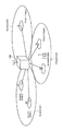
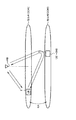
しかしながら、移動局UEが、図1に示すように、カバレッジが異なるセル(例えば、セル#1及びセル#11)における「Component Carrier(例えば、CC#1及びCC#11)」を用いたCAを行う場合や、図2に示すように、リピータが用いられていないセル#1における「Component Carrier(例えば、CC#1)及びリピータ#2が用いられているセル#2における「Component Carrier(例えば、CC#2)」を用いたCAを行う場合には、無線基地局eNBにおける上り信号の受信タイミングが、「Component Carrier」ごとに大幅にずれてしまう場合があるという問題点があった。
However, as shown in FIG. 1, the mobile station UE performs CA using “Component Carrier (for example,
そこで、本発明は、上述の課題に鑑みてなされたものであり、CAが行われている場合であっても、無線基地局eNBにおける上り信号の受信タイミングを一定範囲内に収めることができる移動通信方法、無線基地局及び移動局を提供することを目的とする。 Therefore, the present invention has been made in view of the above-described problems, and even when CA is performed, the mobile base station eNB can move the uplink signal reception timing within a certain range. An object is to provide a communication method, a radio base station, and a mobile station.
本発明の第1の特徴は、移動局が、無線基地局に対して、搬送波周波数が異なる複数のキャリアを用いて上り信号を送信する移動通信方法であって、前記無線基地局が、前記移動局に対して、前記複数のキャリアの各々に対して適用する送信タイミング調整情報を送信する工程Aと、前記移動局が、受信した前記送信タイミング調整情報に基づいて、前記複数のキャリアの各々における上り信号の送信タイミングを調整する工程Bとを有することを要旨とする。 A first feature of the present invention is a mobile communication method in which a mobile station transmits an uplink signal to a radio base station using a plurality of carriers having different carrier frequencies, wherein the radio base station Step A for transmitting transmission timing adjustment information applied to each of the plurality of carriers to the station, and the mobile station in each of the plurality of carriers based on the received transmission timing adjustment information And a step B of adjusting the transmission timing of the uplink signal.
本発明の第2の特徴は、移動局から、搬送波周波数が異なる複数のキャリアを用いて送信された上り信号を受信するように構成されている無線基地局であって、 前記移動局に対して、前記複数のキャリアの各々に対して適用する送信タイミング調整情報を送信するように構成されている送信部を具備することを要旨とする。 A second feature of the present invention is a radio base station configured to receive uplink signals transmitted from a mobile station using a plurality of carriers having different carrier frequencies, and The gist of the invention is that it comprises a transmission unit configured to transmit transmission timing adjustment information applied to each of the plurality of carriers.
本発明の第3の特徴は、無線基地局に対して、搬送波周波数が異なる複数のキャリアを用いて上り信号を送信するように構成されている移動局であって、前記無線基地局から、前記複数のキャリアの各々に対して適用する送信タイミング調整情報を受信するように構成されている受信部と、受信した前記送信タイミング調整情報に基づいて、前記複数のキャリアの各々における上り信号の送信タイミングを調整するように構成されている送信部とを具備することを要旨とする。 A third feature of the present invention is a mobile station configured to transmit an uplink signal to a radio base station using a plurality of carriers having different carrier frequencies, from the radio base station, A receiving unit configured to receive transmission timing adjustment information applied to each of the plurality of carriers, and an uplink signal transmission timing in each of the plurality of carriers based on the received transmission timing adjustment information And a transmitter configured to adjust the frequency.
以上説明したように、本発明によれば、CAが行われている場合であっても、無線基地局eNBにおける上り信号の受信タイミングを一定範囲内に収めることができる移動通信方法、無線基地局及び移動局を提供することができる。 As described above, according to the present invention, even when CA is being performed, the mobile communication method, the radio base station, and the radio base station can keep the uplink signal reception timing in the radio base station eNB within a certain range. And mobile stations can be provided.
(本発明の第1の実施形態に係る移動通信システム)
図1乃至及び図5を参照して、本発明の第1の実施形態に係る移動通信システムの構成について説明する。
(Mobile communication system according to the first embodiment of the present invention)
With reference to FIG. 1 thru | or FIG. 5, the structure of the mobile communication system which concerns on the 1st Embodiment of this invention is demonstrated.
本実施形態に係る移動通信システムは、LTE-Advanced方式の移動通信システムであって、移動局UEによるCAを可能とするように構成されている。 The mobile communication system according to the present embodiment is an LTE-Advanced mobile communication system, and is configured to enable CA by the mobile station UE.
例えば、本実施形態に係る移動通信システムは、図1に示すような構成であってもよいし、図2に示すような構成であってもよいし、その他の構成であってもよい。 For example, the mobile communication system according to the present embodiment may be configured as shown in FIG. 1, may be configured as shown in FIG. 2, or may be other configurations.
図1に示す構成では、無線基地局eNB配下に、マクロセルとして、セル#1やセル#2やセル#3等が設けられており、張り出しセルとして、セル#11やセル#12やセル#21やセル#31やセル#32等が設けられている。
In the configuration illustrated in FIG. 1,
ここで、セル#11及びセル#12は、セル#1のカバレッジ内に設けられており、セル#21は、セル#2のカバレッジ内に設けられており、セル#31及びセル#32は、セル#2のカバレッジ内に設けられている。
Here, the
また、セル#1では、CC(Component Carrier)#1が用いられており、セル#2では、CC#2が用いられており、セル#3では、CC#3が用いられており、セル#11では、CC#11が用いられており、セル#12では、CC#12が用いられており、セル#21では、CC#21が用いられており、セル#31では、CC#31が用いられており、セル#32では、CC#32が用いられている。
Also, in
例えば、CC#1やCC#2やCC#3は、2GHz帯内の搬送波周波数を持つ「Component Carrier」であり、CC#11やCC#12やCC#21やCC#31やCC#32は、3.5GHz帯内の搬送波周波数を持つ「Component Carrier」であってもよい。
For example,
例えば、「Component Carrier」の帯域幅は、6RB(Resource Block)、15RB、25RB、50RB、75RB又は100RBのいずれかであってもよい。なお、1RBは、180kHzである。 For example, the bandwidth of “Component Carrier” may be any one of 6 RB (Resource Block), 15 RB, 25 RB, 50 RB, 75 RB, and 100 RB. 1 RB is 180 kHz.
また、図2に示すよう構成では、無線基地局eNB配下に、マクロセルとして、セル#1やセル#2等が設けられている。セル#1では、CC#1が用いられており、セル#2では、CC#2が用いられている。
In the configuration shown in FIG. 2,
例えば、CC#1及びCC#2は、共に、2GHz帯(又は3.5GHz帯)内の搬送波周波数を持つ「Component Carrier」であってもよい。或いは、CC#1は、2GHz帯(又は、3.5GHz帯)内の搬送波周波数を持つ「Component Carrier」であり、CC#2は、3.5GHz帯(又は、2GHz帯)内の搬送波周波数を持つ「Component Carrier」であってもよい。
For example, both
ここで、セル#1には、リピータ(すなわち、ブースタ)が設けられておらず、セル#2には、リピータ#2が設けられている。
Here, the
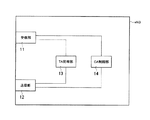
図3に示すように、無線基地局eNBは、受信部11と、送信部12と、TA管理部13と、CA制御部14とを具備している。
As illustrated in FIG. 3, the radio base station eNB includes a
受信部11は、移動局UEから、搬送波周波数が異なる複数の「Component Carrier」におけるPUSCH(Physical Uplink Shared Channel)を介して送信された上りデータ信号又は上り制御信号を受信するように構成されている。
The
CA制御部14は、各移動局UEについてCAを行っているか否かについて管理するように構成されている。
The
TA管理部13は、CAを行っている各移動局UEで用いられている各CCに対して適用すべきTA(Timing Advande、送信タイミング調整情報)の割り当て及び管理を行うように構成されている。
The
ここで、TA管理部13は、CAを行っている各移動局UE内の同一の受信機(IFFT:Inverse Fast Fourier Transform、逆フーリエ変換器)によって処理される複数の「Component Carrier」に対して、同一のTAを割り当てるように構成されていてもよい。
Here, the
すなわち、TA管理部13は、「contiguous CA」のみを行っている移動局UEに対しては、1つのTAのみを割り当てるように構成されていてもよい。ここで、「contiguous CA」は、1つの受信機(IFFT)によって処理されるCAである。
That is, the
同一の受信機(IFFT)で処理される「Component Carrier」では、別々のTAを用いると「Component Carrier」に跨ったOFDMサブキャリア間の直交性が保てなくなるため、同一のTAを用いる必要がある。従って、上述のような構成となる。 In “Component Carrier” processed by the same receiver (IFFT), if different TAs are used, orthogonality between OFDM subcarriers across “Component Carrier” cannot be maintained, so it is necessary to use the same TA. is there. Therefore, the configuration is as described above.
一方、TA管理部13は、CAを行っている各移動局UE内の異なる受信機(IFFT)によって処理される複数の「Component Carrier」に対して、異なるTAを割り当てるように構成されていてもよい。
On the other hand, the
すなわち、TA管理部13は、「non-contiguous CA」を行っている移動局UEに対しては、「non-contiguous CA」の対象である複数の「Component Carrier」の各々に対して独立にTAを割り当てるように構成されている。ここで、「non-contiguous CA」は、複数の受信機(IFFT)によって処理されるCAである。
That is, for the mobile station UE performing “non-continuous CA”, the
送信部12は、CAを行っている移動局UEに対して、複数の「Component Carrier」の各々に対して割り当てられているTAを送信するように構成されている。
The
また、送信部12は、CAを行っている移動局UEに対して、「MAC(Media Access Control)レイヤ」における「CE(Control Element)」によって、上述のTAを送信するように構成されていてもよい。
Further, the
なお、送信部12は、CAを行っている移動局UEに対して、「アンカーキャリア(Anchor Carrier)」を介して、上述のTAを送信するように構成されていてもよい。
Note that the
ここで、アンカーキャリアとは、複数の「Component Carrier」のうち、PDCCH(Physical Downlink Control Channel)信号が送信されるキャリアと定義されていてもよいし、PHICH(Physical HARQ Indicator Channel)信号が送信されるキャリアと定義されていてもよいし、「Semi-persistent Scheduling」が適用される下り信号が送信されるキャリアと定義されていてもよいし、「Semi-persistent Scheduling」が適用されるPUSCH信号(上りデータ信号)に対するPHICH信号が送信されるキャリアと定義されていてもよいし、ページング信号が送信されるキャリアと定義されていてもよいし、DCCH(Dedicated Control Channel)信号が送信されるキャリアと定義されていてもよいし、測定(Measurement)が行われるキャリアと定義されていてもよい。或いは、アンカーキャリアの定義は、上述した定義の組み合わせにより定義されていてもよい。 Here, the anchor carrier may be defined as a carrier in which a PDCCH (Physical Downlink Control Channel) signal is transmitted among a plurality of “Component Carriers”, or a PHICH (Physical HARQ Indicator Channel) signal is transmitted. May be defined as a carrier to which a downlink signal to which “Semi-persistent Scheduling” is applied is transmitted, or a PUSCH signal to which “Semi-persistent Scheduling” is applied ( Uplink data signal) may be defined as a carrier on which a PHICH signal is transmitted, or may be defined as a carrier on which a paging signal is transmitted. May be, to DCCH (Dedicated Control Channel) signal may be defined as carriers transmitted, measured may be defined as the carrier (Measurement) is performed. Or the definition of an anchor carrier may be defined by the combination of the definition mentioned above.
なお、上述のDCCH信号には、「Measurement Report(測定報告)」や、「Handover Command(ハンドオーバ指示信号)」や、「Handover Complete(ハンドオーバ完了信号)」が含まれていてもよい。 The above-described DCCH signal may include “Measurement Report (measurement report)”, “Handover Command (handover instruction signal)”, and “Handover Complete (handover completion signal)”.
また、「アンカーキャリア」は、「メインキャリア(Main Carrier)」と呼ばれてもよい。 The “anchor carrier” may also be referred to as a “main carrier”.
なお、送信部12は、CAを行っている移動局UEに対して、アンカーキャリア以外の任意のキャリアを介して、上述のTAを送信するように構成されていてもよい。
In addition, the
また、送信部12は、個別制御信号或いは報知信号によって、上述のTAを送信するキャリアを指定するように構成されていてもよい。
Moreover, the
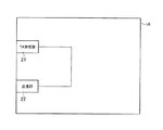
図4に示すように、移動局UEは、TA受信部21と、送信部22とを具備している。
As shown in FIG. 4, the mobile station UE includes a
TA受信部21は、無線基地局eNBから、複数の「Component Carrier」の各々に対して適用するTAを受信するように構成されている。
The
ここで、TA受信部21は、受信した「MACレイヤ」における「TA Command」を指示する「Control Element」から、上述のTAを抽出するように構成されていてもよい。
Here, the
また、TA受信部21は、アンカーキャリアを介して、上述のTAを受信するように構成されていてもよい。
Further, the
送信部22は、無線基地局eNBに対して、搬送波周波数が異なる複数の「Component Carrier」におけるPUSCH又はPUCCHを介して上りデータ信号又は上り制御信号を送信するように構成されている。
The
ここで、送信部22は、TA受信部21によって受信されたTAに基づいて、複数の「Component Carrier」の各々における上り信号の送信タイミングを調整するように構成されている。
Here, the
なお、送信部22は、移動局UE内の同一の受信機(IFFT)によって処理される複数の「Component Carrier」の各々における上り信号の送信タイミングを同一とするように調整してもよい。
Note that the
すなわち、移動局UEが、「contiguous CA」を行っている場合には、送信部22は、複数の「Component Carrier」の各々における上り信号の送信タイミングを同一とするように調整してもよい。
That is, when the mobile station UE performs “continuous CA”, the
一方、送信部22は、移動局UE内の異なるの受信機(IFFT)によって処理される複数の「Component Carrier」の各々における上り信号の送信タイミングを別々に調整してもよい。
On the other hand, the
すなわち、移動局UEが、「non-Contiguous CA」を行っている場合には、送信部22は、複数の「Component Carrier」の各々における上り信号の送信タイミングを別々に調整してもよい。
That is, when the mobile station UE performs “non-Continuous CA”, the
具体的には、図5に示すように、送信部22は、各サブフレームにおける基準時点Tよりも、TAによって指定される時間だけ早い時点で、上り信号を送信するように構成されている。
Specifically, as illustrated in FIG. 5, the
また、CAを行う搬送波周波数が異なる複数の「Component Carrier」のうち、どの「Component Carrier」同士が「contiguous CA」に該当し、どの「Component Carrier」同士が「non-contiguous CA」に該当するのかが、無線基地局eNBによって指示されてもよい。 Also, among a plurality of “Component Carriers” having different carrier frequencies for CA, which “Component Carriers” correspond to “continuous CAs” and which “Component Carriers” correspond to “non-contiguous CAs” May be instructed by the radio base station eNB.
換言すれば、無線基地局eNBは、「contiguous CA」と見なす「Component Carrier」のグループを移動局UEに対して設定することができる。そして、かかるグループごとに識別番号を割り当て、かかる識別番号に基づいてグループごとに異なるTAを指定することができる。 In other words, the radio base station eNB can set a group of “Component Carrier” to be regarded as “continuous CA” for the mobile station UE. An identification number can be assigned to each group, and a different TA can be designated for each group based on the identification number.
また、「non-contiguous CA」であっても、運用形態によっては、同一のTAを適用することが可能な場合もある。 Even in the case of “non-contiguous CA”, the same TA may be applicable depending on the operation mode.
したがって、無線基地局eNBは、同一のTAを適用すべき「Component Carrier」のグループを移動局UEに対して設定し、かかるグループごとに識別番号を割り当て、かかる識別番号に基づいてグループごとに異なるTAを指定することができる。 Accordingly, the radio base station eNB sets a group of “Component Carriers” to which the same TA should be applied to the mobile station UE, assigns an identification number to each group, and varies from group to group based on the identification number. TA can be specified.
ここで、TA受信部21は、受信した「MACレイヤ」における「TA Command」を指示する「Control Element」から、上述のTA及びTAを適用すべきグループの識別番号を抽出するように構成されていてもよい。
Here, the
本発明の第1の実施形態に係る移動通信システムによれば、CAを行っている移動局UEで用いられている各CCに対してTAを割り当てることができるので、CAが行われている場合であっても、無線基地局eNBにおける上り信号の受信タイミングを一定範囲内に収めることができる。 According to the mobile communication system according to the first embodiment of the present invention, since a TA can be assigned to each CC used in the mobile station UE performing CA, the CA is performed. Even so, the reception timing of the uplink signal in the radio base station eNB can be kept within a certain range.
また、本発明の第1の実施形態に係る移動通信システムによれば、「contiguous CA」のみを行っている移動局UEに対しては、1つのTAのみを割り当てることによって、余剰なTAの送信を回避することができる。 In addition, according to the mobile communication system according to the first embodiment of the present invention, only one TA is allocated to the mobile station UE performing only “continuous CA”, thereby transmitting an extra TA. Can be avoided.
また、本発明の第1の実施形態に係る移動通信システムによれば、同一のTAを適用できる「Component Carrier」をグループ化し、グループに対して1つのTAのみを割り当てることによって、余剰なTAの送信を回避することができる。 In addition, according to the mobile communication system according to the first embodiment of the present invention, the “TAR” that can apply the same TA is grouped, and only one TA is assigned to the group, so that the excess TA can be allocated. Transmission can be avoided.
以上に述べた本実施形態の特徴は、以下のように表現されていてもよい。 The characteristics of the present embodiment described above may be expressed as follows.
本実施形態の第1の特徴は、CAを行っている移動局UEが、無線基地局eNBに対して、搬送波周波数が異なる複数の「Component Carrier(例えば、CC#1/CC#2/CC#3/CC#11/CC#12/CC#21/CC#31/CC#32等)」を用いて上り信号を送信する移動通信方法であって、無線基地局eNBが、移動局UEに対して、複数の「Component Carrier」の各々に対して適用するTA(送信タイミング調整情報)を送信する工程Aと、移動局UEが、受信したTAに基づいて、複数の「Component Carrier」の各々における上り信号の送信タイミングを調整する工程Bとを有することを要旨とする。
The first feature of the present embodiment is that the mobile station UE performing CA performs a plurality of “Component Carriers (for example,
本実施形態の第1の特徴において、工程Aにおいて、無線基地局eNBは、移動局UE内の同一の受信機(IFFT)によって処理される複数の「Component Carrier」に対して、同一のTAを送信してもよい。 In the first feature of the present embodiment, in step A, the radio base station eNB assigns the same TA to a plurality of “Component Carriers” processed by the same receiver (IFFT) in the mobile station UE. You may send it.
本実施形態の第1の特徴において、工程Aにおいて、無線基地局eNBは、移動局UE内の異なる受信機(IFFT)によって処理される複数の「Component Carrier」に対して、異なるTAを送信してもよい。 In the first feature of the present embodiment, in step A, the radio base station eNB transmits different TAs to a plurality of “Component Carriers” processed by different receivers (IFFTs) in the mobile station UE. May be.
本実施形態の第1の特徴において、工程Aにおいて、無線基地局eNBは、移動局UEに対して、同一のTAを適用すべき「Component Carrier」のグループの識別情報及び当該同一のTAを送信してもよい。 In the first feature of the present embodiment, in step A, the radio base station eNB transmits, to the mobile station UE, the identification information of the group of “Component Carrier” to which the same TA should be applied and the same TA. May be.
本実施形態の第2の特徴は、移動局UEから、搬送波周波数が異なる複数の「Component Carrier」を用いて送信された上りを受信するように構成されている無線基地局eNBであって、移動局UEに対して、複数の「Component Carrier」の各々に対して適用するTAを送信するように構成されている送信部12を具備することを要旨とする。
A second feature of the present embodiment is a radio base station eNB configured to receive uplinks transmitted from a mobile station UE using a plurality of “Component Carriers” having different carrier frequencies, The gist of the invention is that the station UE includes a
本実施形態の第2の特徴において、送信部12は、移動局UE内の同一の受信機によって処理される複数の「Component Carrier」に対して、同一のTAを送信するように構成されていてもよい。
In the second feature of the present embodiment, the
本実施形態の第2の特徴において、送信部12は、移動局UE内の異なる受信機によって処理される複数の「Component Carrier」に対して、異なるTAを送信するように構成されていてもよい。
In the second feature of the present embodiment, the
本実施形態の第2の特徴において、送信部12は、移動局UEに対して、同一のTAを適用すべき「Component Carrier」のグループの識別情報及び当該同一のTAを送信するように構成されていてもよい。
In the second feature of the present embodiment, the
本実施形態の第3の特徴は、無線基地局eNBに対して、搬送波周波数が異なる複数の「Component Carrier」を用いて上り信号を送信するように構成されている移動局UEであって、無線基地局eNBから、複数の「Component Carrier」の各々に対して適用するTAを受信するように構成されているTA受信部21と、TA受信部21によって受信されたTAに基づいて、複数の「Component Carrier」の各々における上り信号の送信タイミングを調整するように構成されている送信部22とを具備することを要旨とする。
A third feature of the present embodiment is a mobile station UE configured to transmit uplink signals to a radio base station eNB using a plurality of “Component Carriers” having different carrier frequencies, Based on the TA received by the
本実施形態の第3の特徴において、TA受信部21は、移動局UE内の同一の受信機によって処理される複数の「Component Carrier」に対して、同一のTAを受信するように構成されていてもよい。
In the third feature of the present embodiment, the
本実施形態の第3の特徴において、TA受信部21は、移動局UE内の異なる受信機によって処理される複数の「Component Carrier」に対して、異なるTAを受信するように構成されていてもよい。
In the third feature of the present embodiment, the
なお、上述の無線基地局eNB及び移動局UEの動作は、ハードウェアによって実施されてもよいし、プロセッサによって実行されるソフトウェアモジュールによって実施されてもよいし、両者の組み合わせによって実施されてもよい。 Note that the operations of the radio base station eNB and the mobile station UE described above may be implemented by hardware, may be implemented by a software module executed by a processor, or may be implemented by a combination of both. .
ソフトウェアモジュールは、RAM(Random Access Memory)や、フラッシュメモリや、ROM(Read Only Memory)や、EPROM(Erasable Programmable ROM)や、EEPROM(Electronically Erasable and Programmable ROM)や、レジスタや、ハードディスクや、リムーバブルディスクや、CD-ROMといった任意形式の記憶媒体内に設けられていてもよい。 The software module includes a RAM (Random Access Memory), a flash memory, a ROM (Read Only Memory), an EPROM (Erasable Programmable ROM), an EEPROM (Electronically Erasable and Programmable ROM, a Hard Disk, a Registered ROM, a Hard Disk Alternatively, it may be provided in a storage medium of an arbitrary format such as a CD-ROM.
かかる記憶媒体は、プロセッサが当該記憶媒体に情報を読み書きできるように、当該プロセッサに接続されている。また、かかる記憶媒体は、プロセッサに集積されていてもよい。また、かかる記憶媒体及びプロセッサは、ASIC内に設けられていてもよい。かかるASICは、無線基地局eNB及び移動局UE内に設けられていてもよい。また、かかる記憶媒体及びプロセッサは、ディスクリートコンポーネントとして無線基地局eNB及び移動局UE内に設けられていてもよい。 Such a storage medium is connected to the processor so that the processor can read and write information from and to the storage medium. Further, such a storage medium may be integrated in the processor. Such a storage medium and processor may be provided in the ASIC. Such an ASIC may be provided in the radio base station eNB and the mobile station UE. Further, the storage medium and the processor may be provided in the radio base station eNB and the mobile station UE as discrete components.
以上、上述の実施形態を用いて本発明について詳細に説明したが、当業者にとっては、本発明が本明細書中に説明した実施形態に限定されるものではないということは明らかである。本発明は、特許請求の範囲の記載により定まる本発明の趣旨及び範囲を逸脱することなく修正及び変更態様として実施することができる。従って、本明細書の記載は、例示説明を目的とするものであり、本発明に対して何ら制限的な意味を有するものではない。従って、本明細書の記載は、例示説明を目的とするものであり、本発明に対して何ら制限的な意味を有するものではない。 Although the present invention has been described in detail using the above-described embodiments, it is obvious to those skilled in the art that the present invention is not limited to the embodiments described in this specification. The present invention can be implemented as modified and changed modes without departing from the spirit and scope of the present invention defined by the description of the scope of claims. Therefore, the description of the present specification is for illustrative purposes and does not have any limiting meaning to the present invention. Therefore, the description of the present specification is for illustrative purposes and does not have any limiting meaning to the present invention.
eNB…無線基地局
11…受信部
12…送信部
13…TA管理部
14…CA管理部
UE…移動局
21…TA受信部
22…送信部
eNB ...
Claims (3)
前記無線基地局が、前記複数のキャリアのグループ毎に識別情報を割り当てる工程と、
前記無線基地局が、前記移動局に対して、前記識別情報によって送信タイミング調整情報を指定するMACレイヤにおけるControl Elementを送信する工程と、
前記移動局が、受信した前記Control Elementから抽出した前記識別情報によって指定される前記送信タイミング調整情報に基づいて、前記複数のキャリアにおける上り信号の送信タイミングを調整する工程とを有することを特徴とする移動通信方法。 A mobile communication method in which a mobile station transmits an uplink signal to a radio base station using a plurality of carriers having different carrier frequencies,
The wireless base station assigning identification information for each group of the plurality of carriers;
The radio base station, and transmitting to the mobile station, the Control Element in the MAC layer to specify the transmission timing adjustment information by said identification information,
The mobile station has a step of adjusting the transmission timing of uplink signals in the plurality of carriers based on the transmission timing adjustment information specified by the identification information extracted from the received Control Element. Mobile communication method.
前記複数のキャリアのグループ毎に識別情報を割り当てるように構成されており、
前記移動局に対して、前記識別番号によって送信タイミング調整情報を指定するMACレイヤにおけるControl Elementを送信するように構成されていることを特徴とする無線基地局。 A radio base station configured to receive uplink signals transmitted from a mobile station using a plurality of carriers having different carrier frequencies,
It is configured to assign identification information for each group of the plurality of carriers,
Wherein the mobile station, a radio base station, characterized in that it is configured to transmit a Control Element in the MAC layer to specify the transmission timing adjustment information by the identification number.
前記無線基地局から、MACレイヤにおけるControl Elementを受信するように構成されている受信部と、
受信した前記Control Elementから抽出した識別情報によって指定される送信タイミング調整情報に基づいて、前記複数のキャリアにおける上り信号の送信タイミングを調整するように構成されている送信部とを具備しており、
前記識別情報は、前記無線基地局によって前記複数のキャリアのグループ毎に割り当てられるように構成されていることを特徴とする移動局。 A mobile station configured to transmit uplink signals using a plurality of carriers having different carrier frequencies to a radio base station,
A receiving unit configured to receive a control element in the MAC layer from the radio base station;
A transmission unit configured to adjust transmission timing of uplink signals in the plurality of carriers based on transmission timing adjustment information specified by identification information extracted from the received Control Element ;
The mobile station, wherein the identification information is configured to be assigned to each group of the plurality of carriers by the radio base station.
Priority Applications (10)
| Application Number | Priority Date | Filing Date | Title |
|---|---|---|---|
| JP2010003376A JP5156765B2 (en) | 2010-01-08 | 2010-01-08 | Mobile communication method, radio base station, and mobile station |
| MX2012007931A MX2012007931A (en) | 2010-01-08 | 2011-01-07 | Mobile communication method, radio base station and mobile station. |
| KR1020127017797A KR20120104303A (en) | 2010-01-08 | 2011-01-07 | Mobile communication method, radio base station and mobile station |
| CA2787776A CA2787776C (en) | 2010-01-08 | 2011-01-07 | Mobile communication method, radio base station, and mobile station |
| CN201180005637.4A CN102714853B (en) | 2010-01-08 | 2011-01-07 | Method of mobile communication, wireless base station and travelling carriage |
| US13/520,943 US8923200B2 (en) | 2010-01-08 | 2011-01-07 | Mobile communication method, radio base station, and mobile station |
| BR112012016815A BR112012016815A2 (en) | 2010-01-08 | 2011-01-07 | Mobile communication method, base station, and mobile station |
| EP11731861.8A EP2523511B1 (en) | 2010-01-08 | 2011-01-07 | Mobile communication method, radio base station and mobile station |
| PCT/JP2011/050213 WO2011083863A1 (en) | 2010-01-08 | 2011-01-07 | Mobile communication method, radio base station and mobile station |
| ES11731861.8T ES2585392T3 (en) | 2010-01-08 | 2011-01-07 | Mobile communication procedure, radio base station and mobile station |
Applications Claiming Priority (1)
| Application Number | Priority Date | Filing Date | Title |
|---|---|---|---|
| JP2010003376A JP5156765B2 (en) | 2010-01-08 | 2010-01-08 | Mobile communication method, radio base station, and mobile station |
Publications (3)
| Publication Number | Publication Date |
|---|---|
| JP2011142594A JP2011142594A (en) | 2011-07-21 |
| JP2011142594A5 JP2011142594A5 (en) | 2012-07-26 |
| JP5156765B2 true JP5156765B2 (en) | 2013-03-06 |
Family
ID=44305598
Family Applications (1)
| Application Number | Title | Priority Date | Filing Date |
|---|---|---|---|
| JP2010003376A Active JP5156765B2 (en) | 2010-01-08 | 2010-01-08 | Mobile communication method, radio base station, and mobile station |
Country Status (10)
| Country | Link |
|---|---|
| US (1) | US8923200B2 (en) |
| EP (1) | EP2523511B1 (en) |
| JP (1) | JP5156765B2 (en) |
| KR (1) | KR20120104303A (en) |
| CN (1) | CN102714853B (en) |
| BR (1) | BR112012016815A2 (en) |
| CA (1) | CA2787776C (en) |
| ES (1) | ES2585392T3 (en) |
| MX (1) | MX2012007931A (en) |
| WO (1) | WO2011083863A1 (en) |
Families Citing this family (7)
| Publication number | Priority date | Publication date | Assignee | Title |
|---|---|---|---|---|
| JP2013102398A (en) * | 2011-11-09 | 2013-05-23 | Ntt Docomo Inc | Radio communication system, user terminal and radio communication method |
| JP5302438B1 (en) * | 2012-04-20 | 2013-10-02 | 株式会社エヌ・ティ・ティ・ドコモ | Mobile station |
| WO2014101229A1 (en) * | 2012-12-31 | 2014-07-03 | 华为技术有限公司 | Data transmission method and base station |
| JP2015012404A (en) * | 2013-06-27 | 2015-01-19 | 京セラ株式会社 | Communication control method, base station, and user terminal |
| DE102013226977B3 (en) * | 2013-12-20 | 2015-02-05 | Cetitec GmbH | Communication node for a packet-switched data network and method for its operation |
| JP6019199B2 (en) * | 2015-10-28 | 2016-11-02 | 株式会社Nttドコモ | Wireless communication system, user terminal, and wireless communication method |
| WO2018064799A1 (en) * | 2016-10-07 | 2018-04-12 | Qualcomm Incorporated | Power allocation for uplink transmissions |
Family Cites Families (5)
| Publication number | Priority date | Publication date | Assignee | Title |
|---|---|---|---|---|
| TW200805919A (en) * | 2006-07-12 | 2008-01-16 | Matsushita Electric Ind Co Ltd | A diversity receiver and method using the same |
| RU2460241C2 (en) | 2007-01-09 | 2012-08-27 | Нтт Досомо, Инк. | Basic station, mobile communication system, mobile station and method of communication control |
| US8750218B2 (en) * | 2008-09-29 | 2014-06-10 | Blackberry Limited | Message processing in communication systems |
| CN102055700B (en) * | 2009-10-28 | 2015-06-03 | 中兴通讯股份有限公司 | Method and device for CC configuration in CA |
| CN102014477B (en) * | 2009-10-30 | 2013-11-06 | 电信科学技术研究院 | Method, apparatus and system for uplink synchronization |
-
2010
- 2010-01-08 JP JP2010003376A patent/JP5156765B2/en active Active
-
2011
- 2011-01-07 EP EP11731861.8A patent/EP2523511B1/en active Active
- 2011-01-07 ES ES11731861.8T patent/ES2585392T3/en active Active
- 2011-01-07 MX MX2012007931A patent/MX2012007931A/en active IP Right Grant
- 2011-01-07 US US13/520,943 patent/US8923200B2/en active Active
- 2011-01-07 CN CN201180005637.4A patent/CN102714853B/en active Active
- 2011-01-07 WO PCT/JP2011/050213 patent/WO2011083863A1/en active Application Filing
- 2011-01-07 BR BR112012016815A patent/BR112012016815A2/en not_active IP Right Cessation
- 2011-01-07 CA CA2787776A patent/CA2787776C/en not_active Expired - Fee Related
- 2011-01-07 KR KR1020127017797A patent/KR20120104303A/en active Search and Examination
Also Published As
| Publication number | Publication date |
|---|---|
| CN102714853A (en) | 2012-10-03 |
| CA2787776C (en) | 2015-09-15 |
| CN102714853B (en) | 2016-04-27 |
| EP2523511A1 (en) | 2012-11-14 |
| US20130003657A1 (en) | 2013-01-03 |
| EP2523511A4 (en) | 2015-05-27 |
| WO2011083863A1 (en) | 2011-07-14 |
| KR20120104303A (en) | 2012-09-20 |
| CA2787776A1 (en) | 2011-07-14 |
| EP2523511B1 (en) | 2016-05-25 |
| JP2011142594A (en) | 2011-07-21 |
| MX2012007931A (en) | 2012-08-15 |
| ES2585392T3 (en) | 2016-10-05 |
| BR112012016815A2 (en) | 2016-04-19 |
| US8923200B2 (en) | 2014-12-30 |
Similar Documents
| Publication | Publication Date | Title |
|---|---|---|
| JP2022518167A (en) | Bandwidth partial operation and downlink or uplink positioning reference signal scheme | |
| JP5156765B2 (en) | Mobile communication method, radio base station, and mobile station | |
| WO2011043392A1 (en) | Base station device and user device | |
| JP5905749B2 (en) | Wireless base station | |
| WO2013141269A1 (en) | Wireless base station and mobile station | |
| JP5199488B2 (en) | Mobile communication system, radio base station and mobile station | |
| KR20190058628A (en) | Uplink transmission bandwidth control and support | |
| WO2017177378A1 (en) | Method and device for sending and receiving control signaling in communications system | |
| WO2014054386A1 (en) | Mobile station and wireless base station | |
| EP2811800B1 (en) | Mobile communication method, wireless base station, and mobile station | |
| US11502801B2 (en) | Adaptation of ON/OFF mask for NR with different numerologies | |
| WO2011096577A1 (en) | Mobile communication method, wireless base station, and mobile station | |
| US9357531B2 (en) | Radio base station and mobile station | |
| JP6032904B2 (en) | Mobile stations and radio base stations | |
| JPWO2011043393A1 (en) | Base station apparatus and mobile communication method | |
| JP5919035B2 (en) | Mobile station | |
| JP5827914B2 (en) | Mobile station | |
| WO2013115252A1 (en) | Mobile communication method, wireless base station, and mobile station |
Legal Events
| Date | Code | Title | Description |
|---|---|---|---|
| A621 | Written request for application examination |
Free format text: JAPANESE INTERMEDIATE CODE: A621 Effective date: 20110829 |
|
| A521 | Request for written amendment filed |
Free format text: JAPANESE INTERMEDIATE CODE: A523 Effective date: 20120611 |
|
| A871 | Explanation of circumstances concerning accelerated examination |
Free format text: JAPANESE INTERMEDIATE CODE: A871 Effective date: 20120611 |
|
| A975 | Report on accelerated examination |
Free format text: JAPANESE INTERMEDIATE CODE: A971005 Effective date: 20120709 |
|
| A131 | Notification of reasons for refusal |
Free format text: JAPANESE INTERMEDIATE CODE: A131 Effective date: 20120717 |
|
| A521 | Request for written amendment filed |
Free format text: JAPANESE INTERMEDIATE CODE: A523 Effective date: 20120918 |
|
| TRDD | Decision of grant or rejection written | ||
| A01 | Written decision to grant a patent or to grant a registration (utility model) |
Free format text: JAPANESE INTERMEDIATE CODE: A01 Effective date: 20121009 |
|
| A601 | Written request for extension of time |
Free format text: JAPANESE INTERMEDIATE CODE: A601 Effective date: 20121105 |
|
| A602 | Written permission of extension of time |
Free format text: JAPANESE INTERMEDIATE CODE: A602 Effective date: 20121205 |
|
| A61 | First payment of annual fees (during grant procedure) |
Free format text: JAPANESE INTERMEDIATE CODE: A61 Effective date: 20121210 |
|
| FPAY | Renewal fee payment (event date is renewal date of database) |
Free format text: PAYMENT UNTIL: 20151214 Year of fee payment: 3 |
|
| R150 | Certificate of patent or registration of utility model |
Ref document number: 5156765 Country of ref document: JP Free format text: JAPANESE INTERMEDIATE CODE: R150 Free format text: JAPANESE INTERMEDIATE CODE: R150 |
|
| R250 | Receipt of annual fees |
Free format text: JAPANESE INTERMEDIATE CODE: R250 |
|
| R250 | Receipt of annual fees |
Free format text: JAPANESE INTERMEDIATE CODE: R250 |
|
| R250 | Receipt of annual fees |
Free format text: JAPANESE INTERMEDIATE CODE: R250 |
|
| R250 | Receipt of annual fees |
Free format text: JAPANESE INTERMEDIATE CODE: R250 |
|
| R250 | Receipt of annual fees |
Free format text: JAPANESE INTERMEDIATE CODE: R250 |
|
| R250 | Receipt of annual fees |
Free format text: JAPANESE INTERMEDIATE CODE: R250 |
|
| R250 | Receipt of annual fees |
Free format text: JAPANESE INTERMEDIATE CODE: R250 |
|
| R250 | Receipt of annual fees |
Free format text: JAPANESE INTERMEDIATE CODE: R250 |
|
| R250 | Receipt of annual fees |
Free format text: JAPANESE INTERMEDIATE CODE: R250 |