JP5154989B2 - Steam generator - Google Patents
Steam generator Download PDFInfo
- Publication number
- JP5154989B2 JP5154989B2 JP2008079596A JP2008079596A JP5154989B2 JP 5154989 B2 JP5154989 B2 JP 5154989B2 JP 2008079596 A JP2008079596 A JP 2008079596A JP 2008079596 A JP2008079596 A JP 2008079596A JP 5154989 B2 JP5154989 B2 JP 5154989B2
- Authority
- JP
- Japan
- Prior art keywords
- drainage
- time
- tank
- hot water
- function
- Prior art date
- Legal status (The legal status is an assumption and is not a legal conclusion. Google has not performed a legal analysis and makes no representation as to the accuracy of the status listed.)
- Expired - Fee Related
Links
Images
Landscapes
- Air Humidification (AREA)
- Devices For Medical Bathing And Washing (AREA)
Description
本発明は、蒸気発生装置に係り、更に詳しくは、加湿用に利用される湯水を回収するタンクを内部に備えた蒸気発生装置に関する。 The present invention relates to a steam generating device, and more particularly to a steam generating device provided with a tank for collecting hot water used for humidification.
従来より、例えば、特許文献1に開示されているように、熱交換器に湯水を掛けることで、当該湯水を気化して浴室内に蒸気を放出する蒸気発生装置が利用されている。同文献の装置は、熱交換器の下方にタンクを備えており、このタンクにより熱交換器に掛けられて気化せずに流れ落ちる湯水を回収可能に設けられている。蒸気発生装置の運転終了後、装置内を乾燥させるために、タンク内の湯水を排水ポンプで排水可能となっている。 Conventionally, as disclosed in Patent Document 1, for example, a steam generator that vaporizes the hot water and discharges the steam into the bathroom by applying hot water to the heat exchanger has been used. The apparatus of the document includes a tank below the heat exchanger, and is provided so as to be able to collect hot water that is hung on the heat exchanger and flows down without being vaporized by the tank. After the operation of the steam generator, the hot water in the tank can be drained with a drain pump in order to dry the inside of the apparatus.
ところで、蒸気発生装置を設置する浴室によって、排水ポンプに接続される排水配管の管径や長さ、勾配、向き等の配管条件が異なる場合がある。しかしながら、排水ポンプの排水能力は一定となるため、前記配管条件によっては、単位時間当りの排水量が少なすぎたり多すぎたりし、以下に述べる不都合を招来する。 By the way, depending on the bathroom in which the steam generator is installed, the pipe conditions such as the diameter, length, gradient, and direction of the drain pipe connected to the drain pump may be different. However, since the drainage capacity of the drainage pump is constant, depending on the piping conditions, the amount of drainage per unit time is too small or too large, causing the inconvenience described below.
前記排水量が少なすぎると、予め設定した設定時間内に排水を終えることができない、という不都合がある。ここで、前記設定時間を長く設定すれば、タンク内の排水を十分に行えるものの、前記排水量に拘わらず排水のために確保する時間が長くなり、その後の各種作動に移行するまでに無駄な待ち時間を要する、という別異の不都合がある。 If the amount of drainage is too small, there is an inconvenience that drainage cannot be completed within a preset time. Here, if the set time is set long, drainage in the tank can be sufficiently performed, but the time secured for drainage becomes long regardless of the amount of drainage, and wasteful waiting is required before shifting to various operations thereafter. Another disadvantage is that it takes time.
前記排水量が多すぎると、排水配管を流れる湯水の音や、湯水が排水口から吐出される際に発する音が大きくなる、という不都合を生じる。 If the amount of the drainage is too large, there is a disadvantage that the sound of hot water flowing through the drainage pipe and the sound generated when hot water is discharged from the drainage port are increased.
[発明の目的]
本発明は、このような不都合に基づいて案出されたものであり、その目的は、排水配管条件に応じて排水ポンプの単位時間当りの排水量を丁度良い量に設定することができる蒸気発生装置を提供することにある。
[Object of invention]
The present invention has been devised on the basis of such inconveniences, and the purpose thereof is a steam generator that can set the amount of drainage per unit time of the drainage pump to a just good amount according to drainage piping conditions. Is to provide.
前記目的を達成するため、本発明は、湯水を気化する熱交換器と、この熱交換器に掛けられた湯水を回収可能に設けられたタンクと、このタンク内の水位を検出可能な水位センサと、前記タンク内の湯水を排出可能に設けられた排水ポンプと、水位センサの出力に基づいて排水ポンプの単位時間当りの排水量を制御する機能を有する制御装置とを備え、
前記制御装置は、前記排水ポンプでタンク内の湯水を排出するときに、前記水位センサによる所定の上位点の検出時から下位点の検出時に達する間の排水時間を測定し、当該排水時間に基づいて前記単位時間当りの排水量を制御する機能と、所定の許容最短排水時間と前記排水時間とを比較するとともに所定の許容最長排水時間と前記排水時間とを比較する機能と、この比較を行った結果、前記許容最長排水時間より前記排水時間が長い場合、前記単位時間当りの排水量を多くする一方、前記許容最短排水時間より前記排水時間が短い場合、前記単位時間当りの排水量を少なくする機能とを備える、という構成を採っている。
In order to achieve the above object, the present invention provides a heat exchanger for vaporizing hot water, a tank provided so that hot water applied to the heat exchanger can be recovered, and a water level sensor capable of detecting the water level in the tank. And a drainage pump provided so that hot water in the tank can be discharged, and a control device having a function of controlling the amount of drainage per unit time of the drainage pump based on the output of the water level sensor ,
The control device measures the drainage time between the time when a predetermined upper point is detected by the water level sensor and the time when the lower point is detected when the hot water in the tank is discharged by the drainage pump, and based on the drainage time. The function of controlling the amount of drainage per unit time and the function of comparing the predetermined allowable minimum drainage time and the drainage time and comparing the predetermined allowable maximum drainage time and the drainage time were compared. As a result, when the drainage time is longer than the allowable maximum drainage time, the drainage amount per unit time is increased, while when the drainage time is shorter than the allowable minimum drainage time, the drainage amount per unit time is reduced. Ru equipped with, it adopts a configuration that.
また、本発明は、湯水を気化する熱交換器と、この熱交換器に掛けられた湯水を回収可能に設けられたタンクと、このタンク内の水位を検出可能な水位センサと、前記タンク内の湯水を排出可能に設けられた排水ポンプと、水位センサの出力に基づいて排水ポンプの単位時間当りの排水量を制御する機能を有する制御装置とを備え、
前記制御装置は、前記排水ポンプでタンク内の湯水を排出するときに、前記水位センサによる所定の上位点の検出時から下位点の検出時に達する間の排水時間を測定し、当該排水時間に基づいて前記単位時間当りの排水量を制御する機能と、所定の許容最短排水時間範囲と前記排水時間とを比較するとともに所定の許容最長排水時間範囲と前記排水時間とを比較する比較機能と、前記比較機能による比較を行った結果、前記許容最長排水時間範囲より排水時間が長い場合、前記単位時間当りの排水量を多くする一方、前記許容最短排水時間範囲より前記排水時間が短い場合、前記単位時間当りの排水量を少なくする調整機能と、調整機能による調整を行った後で再度前記比較機能による比較を行い、その結果、前記排水時間が前記許容最短排水時間範囲と前記許容最長排水時間範囲とからなる許容時間範囲内でなければ、再度調整機能による調整を行い、前記許容時間範囲内であれば、その時点での単位時間当りの排水量を維持する機能とを備える、という構成を採用している。
The present invention also provides a heat exchanger for vaporizing hot water, a tank provided so as to be able to collect hot water applied to the heat exchanger, a water level sensor capable of detecting the water level in the tank, and the tank A drainage pump provided so as to be able to discharge hot water and a control device having a function of controlling the amount of drainage per unit time of the drainage pump based on the output of the water level sensor,
The control device measures the drainage time between the time when a predetermined upper point is detected by the water level sensor and the time when the lower point is detected when the hot water in the tank is discharged by the drainage pump, and based on the drainage time. A function for controlling the amount of drainage per unit time, a comparison function for comparing a predetermined allowable shortest drainage time range and the drainage time, and comparing a predetermined allowable maximum drainage time range and the drainage time, and the comparison As a result of comparison by function, when the drainage time is longer than the allowable maximum drainage time range, the drainage amount per unit time is increased, while when the drainage time is shorter than the allowable minimum drainage time range, The adjustment function to reduce the amount of discharged water and the comparison by the comparison function again after the adjustment by the adjustment function, and as a result, the drainage time is the allowable shortest discharge. If it is not within the permissible time range consisting of the time range and the permissible longest drainage time range, it is adjusted again by the adjustment function, and if within the permissible time range, the function of maintaining the drainage amount per unit time at that time The structure of being equipped with is adopted .
本発明によれば、水位センサでタンク内の水位を検出し、この水位センサの出力に基づいて排水ポンプの単位時間当りの排水量を制御するので、前記単位時間当りの排水量が少なすぎたり多すぎたりすることを回避可能となる。具体的には、水位センサが異なる高さ位置を検出する間の排水時間に応じて前記単位時間当りの排水量を増減するように制御することにより、前記単位時間当りの排水量の適正化を図ることができる。これにより、前記排水量が少なすぎてタンク内の排水が不十分となったり、排水が長時間化することを防止でき、且つ、前記単位時間当りの排水量が多すぎて排水音が大きくなることを抑制することが可能となる。 According to the present invention, the water level in the tank is detected by the water level sensor, and the drainage amount per unit time of the drainage pump is controlled based on the output of the water level sensor, so that the drainage amount per unit time is too small or too much. Can be avoided. Specifically, the drainage amount per unit time is optimized by controlling to increase or decrease the drainage amount per unit time according to the drainage time while the water level sensor detects different height positions. Can do. As a result, it is possible to prevent the drainage amount in the tank from becoming insufficient due to the amount of the wastewater being too small or the drainage time from being prolonged, and the amount of drainage per unit time is too much to increase the sound of drainage. It becomes possible to suppress.
また、許容時間範囲内に排水時間が収まるまで前記単位時間当りの排水量の調整を行い、許容時間範囲内に排水時間が収まれば、その時点での単位時間当りの排水量を維持した場合、排水量を丁度良い量に容易に設定可能となる。 In addition, the drainage amount per unit time is adjusted until the drainage time is within the allowable time range, and if the drainage time is within the allowable time range, the drainage amount is maintained when the drainage amount per unit time at that time is maintained. It can be easily set to just the right amount.
以下、本発明の好ましい実施の形態について図面を参照しながら説明する。 Hereinafter, preferred embodiments of the present invention will be described with reference to the drawings.
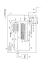
図1には、実施形態に係る蒸気発生装置の基本構成図が示されている。この図において、蒸気発生装置10は、本実施形態では、浴室ユニットを構成する天井パネルに取付けられ、下方の浴室内に蒸気を放出する。蒸気発生装置10は、筐体11内に設けられた熱交換器12と、熱交換器12に向かって吐水可能に設けられた吐水手段13と、熱交換器12の下方に設けられたタンク15と、このタンク15内の水位を検出可能な水位センサ16と、前記タンク15内の湯水を排出可能に設けられた排水ポンプ17と、水位センサ16の出力を入力として排水ポンプ17を制御可能な制御装置18とを備えて構成されている。
FIG. 1 shows a basic configuration diagram of a steam generator according to an embodiment. In this figure, the
前記熱交換器12は、連結配管20を介して所定間隔毎に並設された多数枚のフィン21を備えている。連結配管20は、給湯器22に接続された温水供給配管23及び湯水回収配管24に連通している。フィン21は、温水供給配管23を通じて連結配管20に温水を供給することで加熱される。連結配管20を通過した温水は、湯水回収配管24を通じて給湯器22に戻される。温水供給配管23には、電磁弁25が設けられ、この電磁弁25により温水供給配管23に供給する湯水量を制御できるようになっている。
The
前記吐水手段13は、前記フィン21に向かって水を吐出するノズル27Aを先端に備えた吐出配管27と、タンク15内の水を吐出配管27に供給する循環ポンプ28とを備えている。ノズル27Aから吐出された湯水は、フィン21により加熱されて気化され、すなわち蒸気となり、この蒸気は、ファン30の作動により吸込口31から吸い込んだ浴室内の空気と共に吹出口32から放出される。
The water discharge means 13 includes a
前記タンク15内には、前記給湯器22に接続された供給配管34から湯水が供給される。供給配管34には、電磁弁35が設けられ、タンク15内に供給する湯水量をその開弁時間で調整できるようになっている。また、タンク15は、前記吐水手段13によりフィン21に掛けられて流れ落ちた湯水を受け入れ、当該湯水を回収可能に設けられている。回収されたタンク15内の湯水は、循環ポンプ28を作動することでノズル27Aから再度フィン21に掛けられ、タンク15、吐水手段13及び熱交換器12において循環可能となる。
Hot water is supplied into the tank 15 from a
前記水位センサ16は、高さが異なる上位点及び下位点を検出し、当該検出時を制御手段に出力可能に設けられている。具体的には、水位センサ16は、フロートスイッチや圧力センサを使用することができる。なお、水位センサ16は、一点の設定水位だけを検出可能なフロートスイッチとし、その設定水位非検出状態から検出状態へ移行した時と検出状態から非検出状態へ移行した時との両方を利用することで、前記上位点及び下位点の検出時を得るようしてもよい。
The
前記排水ポンプ17は、排水配管36に接続され、この排水配管36を通じて浴室の洗い場領域や排水経路に排水可能に設けられている。排水ポンプ17は、図示しない回転子を含み、当該回転子の回転数の増減に応じて単位時間当りの排水量が増減するようになっている。
The drainage pump 17 is connected to a
前記制御装置18は、前記水位センサ16の設定水位検出・設定水位非検出の出力信号を入力する機能と、前記電磁弁35の作動を制御する機能と、前記排水ポンプ17の作動及び前記回転数を増減して前記排水量を調整する機能とを備えている。また、制御装置18は、水位センサ16における前記上位点の検出時から下位点の検出時に達する間の排水時間を測定するタイマー機能と、前記排水時間と予め設定した時間とを比較する機能と、前記排水時間等の条件から前記排水ポンプ17の回転数を演算する機能とを備えている。前記電磁弁35及び排水ポンプ17の制御は、制御装置18に入力される水位センサ16の出力に基づいて行われる。
The
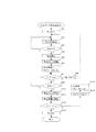
次に、前記排水ポンプ17の前記回転数の設定方法について、図2のフローチャートを用いて説明する。ここでは、水位センサ16が検出する上位点H及び下位点Lが予め設定され、排水ポンプ17の回転数の初回設定値R1と、排水時間の許容最短排水時間Ts及び許容最長排水時間Tlと、アラーム排水時間Tmaxとが制御手段18に入力、記憶されている。
Next, a method for setting the rotational speed of the drain pump 17 will be described with reference to the flowchart of FIG. Here, the upper point H and the lower point L detected by the
先ず、排水ポンプ17の初期回転数Rsを初回設定値R1とし(ステップS1)、制御手段18により電磁弁35を開弁し、供給配管34からタンク15内に湯水を供給する(ステップS2)。湯水の供給中、水位センサ16でタンク15の水位が上位点Hに達しているか否かを検出し(ステップS3)、上位点Hに達していることを検出しなければ、湯水の供給を継続する。水位センサ16でタンク15の水位が上位点Hに達したことを検出したときに、制御手段18により電磁弁35を閉弁し、供給配管34からの湯水の供給を停止する(ステップS4)。次に、制御手段18により排水ポンプ17を初期回転数Rsで作動し、タンク15内の湯水の排出を開始する(ステップS5)。これと同時に制御手段18の前述したタイマー機能のタイマーをスタートし排水時間Tの測定を開始する(ステップS6)。
First, the initial rotational speed Rs of the drain pump 17 is set to the initial set value R1 (step S1), the
排水ポンプ17での排水中、アラーム排水時間Tmaxと排水時間Tとを比較し(ステップS7)、排水時間Tがアラーム排水時間Tmaxより長い場合、操作パネル等を介してアラームを発する(ステップS8)。排水時間Tがアラーム排水時間Tmax以下である場合、水位センサ16でタンク15の水位が下位点Lに達しているか否かを検出し(ステップS9)、下位点Lに達していることを検出しなければ、排水を継続する。水位センサ16でタンク15の水位が下位点Lに達したことを検出すると同時に、制御手段18により排水ポンプ17の作動を停止する(ステップS10)。また、これと同時に、前記タイマー機能のタイマーをストップし、排水時間Tの測定を終了する(ステップS11)。次に、当該排水時間Tが許容最短排水時間Tsと許容最長排水時間Tlとの間の許容範囲内であるか否かを制御手段18で比較する(ステップS12)。
During drainage by the drainage pump 17, the alarm drainage time Tmax and the drainage time T are compared (step S7). If the drainage time T is longer than the alarm drainage time Tmax, an alarm is issued via the operation panel or the like (step S8). . If the drainage time T is less than or equal to the alarm drainage time Tmax, the
排水時間Tが前記許容範囲内であれば、前記排水ポンプ17の初期回転数Rsを通常回転数R(ステップS13)に設定して制御手段18で記憶し、その後の排水ポンプ17の作動は通常回転数Rで行う。排水時間Tが前記許容範囲外であれば、前記タイマー機能の排水時間Tをリセットし(ステップS14)、初期回転数Rsを補正値dにより補正して(ステップS15)、前記ステップS2に戻る。前記ステップS12において排水時間Tが前記範囲内となるまで、前述したフローを繰り返し行う。 If the drainage time T is within the allowable range, the initial rotation speed Rs of the drainage pump 17 is set to the normal rotation speed R (step S13) and stored in the control means 18, and the subsequent operation of the drainage pump 17 is normal. This is performed at the rotation speed R. If the drainage time T is outside the allowable range, the drainage time T of the timer function is reset (step S14), the initial rotation speed Rs is corrected by the correction value d (step S15), and the process returns to step S2. In step S12, the above-described flow is repeated until the drainage time T falls within the range.
次いで、前記ステップS15での初期回転数Rsの補正について以下に詳述する。ここでは、前記上位点H及び下位点L間のタンク15の容積Lが制御手段18に入力、記憶されている。 Next, the correction of the initial rotational speed Rs in step S15 will be described in detail below. Here, the volume L of the tank 15 between the upper point H and the lower point L is inputted and stored in the control means 18.
第n回目(nは自然数)に測定した排水時間Tを第n回排水時間Tnとして記憶し、以下の式(1)により、第n回排水時間Tnの測定時における排水ポンプ17の単位時間当りの排水量Qnを制御手段18で演算する。
Qn=L/Tn・・・(1)
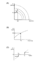
図3(A)のポンプ回転数とP−Q特性のグラフと、前記排水量Qnと、排水ポンプ17の初期回転数Rsとから排水配管抵抗Pnを制御手段18で演算する。この排水配管抵抗Pnと、図3(B)の最適排水量時のP−R特性のグラフとから最適回転数Riを制御手段18で演算する。
以下の式(2)により、前記初期回転数Rsと最適回転数Riとから、補正量dを制御手段18で演算する。
d=Ri−Rs・・・(2)
これにより、初期回転数Rsが最適回転数Riより少ない場合、補正量dが正数となり、初期回転数Rsが最適回転数Riより多い場合、補正量dが負数となる。従って、前記ステップ15の補正において、許容最長排水時間Tlより排水時間Tが長い場合、正数の補正値dにより前記排水量が増えるように初期回転数Rsを多くし、許容最短排水時間Tsより排水時間Tが短い場合、負数の補正値dにより前記単位時間当りの排水量が減るように初期回転数Rsを少なくする演算が制御手段18で行われる。
The drainage time T measured at the nth time (n is a natural number) is stored as the nth drainage time Tn, and per unit time of the drainage pump 17 at the time of measuring the nth drainage time Tn by the following equation (1) Is calculated by the control means 18.
Qn = L / Tn (1)
The drainage pipe resistance Pn is calculated by the control means 18 from the graph of the pump rotation speed and PQ characteristics shown in FIG. 3A, the drainage amount Qn, and the initial rotation speed Rs of the drainage pump 17. The optimal rotation speed Ri is calculated by the control means 18 from the drain pipe resistance Pn and the graph of the PR characteristic at the optimal drainage amount in FIG.
The correction amount d is calculated by the control means 18 from the initial rotational speed Rs and the optimal rotational speed Ri according to the following equation (2).
d = Ri−Rs (2)
Thereby, when the initial rotational speed Rs is smaller than the optimal rotational speed Ri, the correction amount d becomes a positive number, and when the initial rotational speed Rs is larger than the optimal rotational speed Ri, the correction amount d becomes a negative number. Accordingly, when the drainage time T is longer than the allowable longest drainage time Tl in the correction in the step 15, the initial rotational speed Rs is increased so that the drainage amount is increased by a positive correction value d, and the drainage is performed from the allowable shortest drainage time Ts. When the time T is short, the control means 18 performs an operation for decreasing the initial rotational speed Rs so that the amount of drainage per unit time is reduced by the negative correction value d.
ここで、初期回転数Rsの補正は、図3(C)のグラフを用いて演算してもよい。具体的には、排水ポンプ17の排水の補正量が第1回目の排水量Q1の10〜30%程度となるように補正値dを設定する。図3(C)中実線のグラフでは、補正値dの絶対値が一定となり、同図中点線のグラフでは、許容最短排水時間Tsと許容最長排水時間Tlとの間の範囲から排水時間Tから離れるに従って補正値dの絶対値が大きくなり、補正される単位時間当りの排水量の絶対値も大きくなる。 Here, the correction of the initial rotational speed Rs may be calculated using the graph of FIG. Specifically, the correction value d is set so that the correction amount of the drainage of the drainage pump 17 is about 10 to 30% of the first drainage amount Q1. In the solid line graph in FIG. 3C, the absolute value of the correction value d is constant. In the dotted line graph in FIG. 3C, from the drainage time T from the range between the allowable shortest drainage time Ts and the allowable longest drainage time Tl. As the distance increases, the absolute value of the correction value d increases, and the absolute value of the amount of drainage corrected per unit time also increases.
従って、このような実施形態によれば、前述のように排水ポンプ17の回転数を調整することで、排水配管36の条件が変化した場合であっても、前記単位時間当りの排水量が少なすぎたり多すぎたりすることなく適度に保つことが可能となる。また、前記ステップS13の前段階を試運転とした場合、当該試運転で前記単位時間当りの排水量が調整可能となり、試運転後の通常運転では常に丁度良い単位時間当りの排水量で使用することができる。
Therefore, according to such an embodiment, the amount of drainage per unit time is too small even when the condition of the
本発明を実施するための最良の構成、方法などは、以上の記載で開示されているが、本発明は、これに限定されるものではない。
すなわち、本発明は、特定の実施の形態に関して特に図示し、且つ、説明されているが、本発明の技術的思想及び目的の範囲から逸脱することなく、以上に述べた実施形態に対し、形状、その他の詳細な構成において、当業者が様々な変形を加えることができるものである。
従って、上記に開示した形状などを限定した記載は、本発明の理解を容易にするために例示的に記載したものであり、本発明を限定するものではないから、それらの形状などの限定の一部若しくは全部の限定を外した部材の名称での記載は、本発明に含まれるものである。
The best configuration, method and the like for carrying out the present invention have been disclosed in the above description, but the present invention is not limited to this.
That is, the present invention has been particularly shown and described with respect to particular embodiments, but is not limited to the embodiments described above without departing from the scope and spirit of the present invention. In other detailed configurations, those skilled in the art can make various modifications.
Therefore, the description limited to the shape disclosed above is an example for easy understanding of the present invention, and does not limit the present invention. The description by the name of the member which remove | excluded one part or all part is included in this invention.
例えば、排水ポンプ17は、前記排水量を制御できる限りにおいて、回転数とは別の構成部分の作動を制御してもよい。 For example, the drain pump 17 may control the operation of a component other than the rotational speed as long as the drainage amount can be controlled.
また、蒸気発生装置10の取付け位置は、特に限定されるものでなく、浴室の壁パネルに取付けたり、浴室内のエプロン下部に組み込んでもよい。
Moreover, the attachment position of the
更に、前記許容最短排水時間Ts及び許容最長排水時間Tlは、例えば、数秒間の時間範囲とし、且つ、排水時間Tの許容範囲としてもよい。 Further, the allowable shortest drainage time Ts and the allowable longest drainage time Tl may be a time range of several seconds, for example, and may be an allowable range of the drainage time T.
また、タンク15は、フィン21に掛けられて流れ落ちた湯水を受け入れられればいかなる形状であってもよい。
Further, the tank 15 may have any shape as long as it can receive hot water that has been hung on the
10・・・蒸気発生装置、12・・・熱交換器、15・・・タンク、16・・・水位センサ、17・・・排水ポンプ、18・・・制御装置
DESCRIPTION OF
Claims (2)
前記制御装置は、前記排水ポンプでタンク内の湯水を排出するときに、前記水位センサによる所定の上位点の検出時から下位点の検出時に達する間の排水時間を測定し、当該排水時間に基づいて前記単位時間当りの排水量を制御する機能と、所定の許容最短排水時間と前記排水時間とを比較するとともに所定の許容最長排水時間と前記排水時間とを比較する機能と、この比較を行った結果、前記許容最長排水時間より前記排水時間が長い場合、前記単位時間当りの排水量を多くする一方、前記許容最短排水時間より前記排水時間が短い場合、前記単位時間当りの排水量を少なくする機能とを備えていることを特徴とする蒸気発生装置。 A heat exchanger that vaporizes hot water, a tank that can recover the hot water applied to the heat exchanger, a water level sensor that can detect the water level in the tank, and the hot water in the tank can be discharged. A drainage pump provided , and a control device having a function of controlling the amount of drainage per unit time of the drainage pump based on the output of the water level sensor ,
The control device measures the drainage time between the time when a predetermined upper point is detected by the water level sensor and the time when the lower point is detected when the hot water in the tank is discharged by the drainage pump, and based on the drainage time. The function of controlling the amount of drainage per unit time and the function of comparing the predetermined allowable minimum drainage time and the drainage time and comparing the predetermined allowable maximum drainage time and the drainage time were compared. As a result, when the drainage time is longer than the allowable maximum drainage time, the drainage amount per unit time is increased, while when the drainage time is shorter than the allowable minimum drainage time, the drainage amount per unit time is reduced. steam generator, characterized in that it comprises.
前記制御装置は、前記排水ポンプでタンク内の湯水を排出するときに、前記水位センサによる所定の上位点の検出時から下位点の検出時に達する間の排水時間を測定し、当該排水時間に基づいて前記単位時間当りの排水量を制御する機能と、所定の許容最短排水時間範囲と前記排水時間とを比較するとともに所定の許容最長排水時間範囲と前記排水時間とを比較する比較機能と、前記比較機能による比較を行った結果、前記許容最長排水時間範囲より排水時間が長い場合、前記単位時間当りの排水量を多くする一方、前記許容最短排水時間範囲より前記排水時間が短い場合、前記単位時間当りの排水量を少なくする調整機能と、調整機能による調整を行った後で再度前記比較機能による比較を行い、その結果、前記排水時間が前記許容最短排水時間範囲と前記許容最長排水時間範囲とからなる許容時間範囲内でなければ、再度調整機能による調整を行い、前記許容時間範囲内であれば、その時点での単位時間当りの排水量を維持する機能とを備えていることを特徴とする蒸気発生装置。 A heat exchanger that vaporizes hot water, a tank that can recover the hot water applied to the heat exchanger, a water level sensor that can detect the water level in the tank, and the hot water in the tank can be discharged. A drainage pump provided, and a control device having a function of controlling the amount of drainage per unit time of the drainage pump based on the output of the water level sensor,
The control device measures the drainage time between the time when a predetermined upper point is detected by the water level sensor and the time when the lower point is detected when the hot water in the tank is discharged by the drainage pump, and based on the drainage time. A function for controlling the amount of drainage per unit time, a comparison function for comparing a predetermined allowable shortest drainage time range and the drainage time, and comparing a predetermined allowable maximum drainage time range and the drainage time, and the comparison As a result of comparison by function, when the drainage time is longer than the allowable maximum drainage time range, the drainage amount per unit time is increased, while when the drainage time is shorter than the allowable minimum drainage time range, The adjustment function to reduce the amount of discharged water and the comparison by the comparison function again after the adjustment by the adjustment function, and as a result, the drainage time is the allowable shortest discharge. If it is not within the permissible time range consisting of the time range and the permissible longest drainage time range, it is adjusted again by the adjustment function, and if within the permissible time range, the function of maintaining the drainage amount per unit time at that time steam generator characterized by comprising and.
Priority Applications (1)
| Application Number | Priority Date | Filing Date | Title |
|---|---|---|---|
| JP2008079596A JP5154989B2 (en) | 2008-03-26 | 2008-03-26 | Steam generator |
Applications Claiming Priority (1)
| Application Number | Priority Date | Filing Date | Title |
|---|---|---|---|
| JP2008079596A JP5154989B2 (en) | 2008-03-26 | 2008-03-26 | Steam generator |
Publications (2)
| Publication Number | Publication Date |
|---|---|
| JP2009236336A JP2009236336A (en) | 2009-10-15 |
| JP5154989B2 true JP5154989B2 (en) | 2013-02-27 |
Family
ID=41250516
Family Applications (1)
| Application Number | Title | Priority Date | Filing Date |
|---|---|---|---|
| JP2008079596A Expired - Fee Related JP5154989B2 (en) | 2008-03-26 | 2008-03-26 | Steam generator |
Country Status (1)
| Country | Link |
|---|---|
| JP (1) | JP5154989B2 (en) |
Families Citing this family (1)
| Publication number | Priority date | Publication date | Assignee | Title |
|---|---|---|---|---|
| JP2010002145A (en) * | 2008-06-20 | 2010-01-07 | Mitsubishi Electric Corp | Equipment using cartridge-type tank |
Family Cites Families (3)
| Publication number | Priority date | Publication date | Assignee | Title |
|---|---|---|---|---|
| JP2004028412A (en) * | 2002-06-24 | 2004-01-29 | Takutoron Kk | Mist generation mechanism for minus ion generator |
| JP2007003132A (en) * | 2005-06-27 | 2007-01-11 | Matsushita Electric Ind Co Ltd | Air conditioner |
| JP2007267961A (en) * | 2006-03-31 | 2007-10-18 | Tokyo Gas Co Ltd | Steam generator |
-
2008
- 2008-03-26 JP JP2008079596A patent/JP5154989B2/en not_active Expired - Fee Related
Also Published As
| Publication number | Publication date |
|---|---|
| JP2009236336A (en) | 2009-10-15 |
Similar Documents
| Publication | Publication Date | Title |
|---|---|---|
| JP5053272B2 (en) | Method for cleaning a boiler system for use with a steam device | |
| AU2008358505B2 (en) | Method for controlling a hot water temperature in using low flux in hot water supply system | |
| CN108954849A (en) | A kind of control method and control system of the open type heat storage water tank of electronic water closet | |
| CN104898738B (en) | Constant temperature heating control method for electronic toilet | |
| CN105953416A (en) | Water heater and draining and cleaning control method for water heater | |
| JP5312215B2 (en) | Heat recovery system | |
| JP5313078B2 (en) | Flush toilet | |
| JP2004290679A (en) | Apparatus for preparation of hot water | |
| JP5154989B2 (en) | Steam generator | |
| CN107687705B (en) | A water heater and its control method | |
| CN209541185U (en) | A kind of control system of the open type heat storage water tank of electronic water closet | |
| JP3810203B2 (en) | Memorial device with water heater | |
| JP2007054780A (en) | Condensed water treatment device, and hot water supplying apparatus provided therewith | |
| KR101524765B1 (en) | Appatatus and method for controlling warm water supplier | |
| JP4934646B2 (en) | Hot water filling device | |
| JP6247105B2 (en) | Water heater | |
| JP5383401B2 (en) | Drain drainage device | |
| CN114251828A (en) | Instantaneous heating device, control method and control device thereof, water treatment device and medium | |
| JP3975640B2 (en) | Water heater | |
| JP2005134028A (en) | Hot water heater | |
| JP3987271B2 (en) | Bathtub water level control device | |
| JP5819247B2 (en) | Bath equipment | |
| JP2013128650A (en) | Hot water replenishing control system | |
| JP7225956B2 (en) | Sanitary washing equipment and toilet equipment | |
| JPH0820107B2 (en) | Automatic bath equipment |
Legal Events
| Date | Code | Title | Description |
|---|---|---|---|
| A621 | Written request for application examination |
Free format text: JAPANESE INTERMEDIATE CODE: A621 Effective date: 20110131 |
|
| A977 | Report on retrieval |
Free format text: JAPANESE INTERMEDIATE CODE: A971007 Effective date: 20120420 |
|
| A131 | Notification of reasons for refusal |
Free format text: JAPANESE INTERMEDIATE CODE: A131 Effective date: 20120424 |
|
| A521 | Written amendment |
Free format text: JAPANESE INTERMEDIATE CODE: A523 Effective date: 20120615 |
|
| TRDD | Decision of grant or rejection written | ||
| A01 | Written decision to grant a patent or to grant a registration (utility model) |
Free format text: JAPANESE INTERMEDIATE CODE: A01 Effective date: 20121127 |
|
| A61 | First payment of annual fees (during grant procedure) |
Free format text: JAPANESE INTERMEDIATE CODE: A61 Effective date: 20121206 |
|
| FPAY | Renewal fee payment (event date is renewal date of database) |
Free format text: PAYMENT UNTIL: 20151214 Year of fee payment: 3 |
|
| R150 | Certificate of patent or registration of utility model |
Ref document number: 5154989 Country of ref document: JP Free format text: JAPANESE INTERMEDIATE CODE: R150 Free format text: JAPANESE INTERMEDIATE CODE: R150 |
|
| S111 | Request for change of ownership or part of ownership |
Free format text: JAPANESE INTERMEDIATE CODE: R313115 |
|
| R350 | Written notification of registration of transfer |
Free format text: JAPANESE INTERMEDIATE CODE: R350 |
|
| R250 | Receipt of annual fees |
Free format text: JAPANESE INTERMEDIATE CODE: R250 |
|
| R250 | Receipt of annual fees |
Free format text: JAPANESE INTERMEDIATE CODE: R250 |
|
| R250 | Receipt of annual fees |
Free format text: JAPANESE INTERMEDIATE CODE: R250 |
|
| S111 | Request for change of ownership or part of ownership |
Free format text: JAPANESE INTERMEDIATE CODE: R313117 |
|
| R350 | Written notification of registration of transfer |
Free format text: JAPANESE INTERMEDIATE CODE: R350 |
|
| R250 | Receipt of annual fees |
Free format text: JAPANESE INTERMEDIATE CODE: R250 |
|
| LAPS | Cancellation because of no payment of annual fees |