JP5154948B2 - Method for defining coating fluid pattern - Google Patents
Method for defining coating fluid pattern Download PDFInfo
- Publication number
- JP5154948B2 JP5154948B2 JP2007549378A JP2007549378A JP5154948B2 JP 5154948 B2 JP5154948 B2 JP 5154948B2 JP 2007549378 A JP2007549378 A JP 2007549378A JP 2007549378 A JP2007549378 A JP 2007549378A JP 5154948 B2 JP5154948 B2 JP 5154948B2
- Authority
- JP
- Japan
- Prior art keywords
- applicator roll
- coating fluid
- coating
- roll surface
- microspheres
- Prior art date
- Legal status (The legal status is an assumption and is not a legal conclusion. Google has not performed a legal analysis and makes no representation as to the accuracy of the status listed.)
- Expired - Fee Related
Links
Images


Classifications
-
- B—PERFORMING OPERATIONS; TRANSPORTING
- B05—SPRAYING OR ATOMISING IN GENERAL; APPLYING FLUENT MATERIALS TO SURFACES, IN GENERAL
- B05C—APPARATUS FOR APPLYING FLUENT MATERIALS TO SURFACES, IN GENERAL
- B05C1/00—Apparatus in which liquid or other fluent material is applied to the surface of the work by contact with a member carrying the liquid or other fluent material, e.g. a porous member loaded with a liquid to be applied as a coating
- B05C1/04—Apparatus in which liquid or other fluent material is applied to the surface of the work by contact with a member carrying the liquid or other fluent material, e.g. a porous member loaded with a liquid to be applied as a coating for applying liquid or other fluent material to work of indefinite length
- B05C1/08—Apparatus in which liquid or other fluent material is applied to the surface of the work by contact with a member carrying the liquid or other fluent material, e.g. a porous member loaded with a liquid to be applied as a coating for applying liquid or other fluent material to work of indefinite length using a roller or other rotating member which contacts the work along a generating line
- B05C1/0839—Apparatus in which liquid or other fluent material is applied to the surface of the work by contact with a member carrying the liquid or other fluent material, e.g. a porous member loaded with a liquid to be applied as a coating for applying liquid or other fluent material to work of indefinite length using a roller or other rotating member which contacts the work along a generating line the work being unsupported at the line of contact between the coating roller and the work
-
- B—PERFORMING OPERATIONS; TRANSPORTING
- B05—SPRAYING OR ATOMISING IN GENERAL; APPLYING FLUENT MATERIALS TO SURFACES, IN GENERAL
- B05D—PROCESSES FOR APPLYING FLUENT MATERIALS TO SURFACES, IN GENERAL
- B05D1/00—Processes for applying liquids or other fluent materials
- B05D1/28—Processes for applying liquids or other fluent materials performed by transfer from the surfaces of elements carrying the liquid or other fluent material, e.g. brushes, pads, rollers
-
- B—PERFORMING OPERATIONS; TRANSPORTING
- B05—SPRAYING OR ATOMISING IN GENERAL; APPLYING FLUENT MATERIALS TO SURFACES, IN GENERAL
- B05C—APPARATUS FOR APPLYING FLUENT MATERIALS TO SURFACES, IN GENERAL
- B05C1/00—Apparatus in which liquid or other fluent material is applied to the surface of the work by contact with a member carrying the liquid or other fluent material, e.g. a porous member loaded with a liquid to be applied as a coating
- B05C1/04—Apparatus in which liquid or other fluent material is applied to the surface of the work by contact with a member carrying the liquid or other fluent material, e.g. a porous member loaded with a liquid to be applied as a coating for applying liquid or other fluent material to work of indefinite length
- B05C1/08—Apparatus in which liquid or other fluent material is applied to the surface of the work by contact with a member carrying the liquid or other fluent material, e.g. a porous member loaded with a liquid to be applied as a coating for applying liquid or other fluent material to work of indefinite length using a roller or other rotating member which contacts the work along a generating line
- B05C1/0817—Apparatus in which liquid or other fluent material is applied to the surface of the work by contact with a member carrying the liquid or other fluent material, e.g. a porous member loaded with a liquid to be applied as a coating for applying liquid or other fluent material to work of indefinite length using a roller or other rotating member which contacts the work along a generating line characterised by means for removing partially liquid or other fluent material from the roller, e.g. scrapers
-
- B—PERFORMING OPERATIONS; TRANSPORTING
- B05—SPRAYING OR ATOMISING IN GENERAL; APPLYING FLUENT MATERIALS TO SURFACES, IN GENERAL
- B05C—APPARATUS FOR APPLYING FLUENT MATERIALS TO SURFACES, IN GENERAL
- B05C1/00—Apparatus in which liquid or other fluent material is applied to the surface of the work by contact with a member carrying the liquid or other fluent material, e.g. a porous member loaded with a liquid to be applied as a coating
- B05C1/04—Apparatus in which liquid or other fluent material is applied to the surface of the work by contact with a member carrying the liquid or other fluent material, e.g. a porous member loaded with a liquid to be applied as a coating for applying liquid or other fluent material to work of indefinite length
- B05C1/08—Apparatus in which liquid or other fluent material is applied to the surface of the work by contact with a member carrying the liquid or other fluent material, e.g. a porous member loaded with a liquid to be applied as a coating for applying liquid or other fluent material to work of indefinite length using a roller or other rotating member which contacts the work along a generating line
- B05C1/0826—Apparatus in which liquid or other fluent material is applied to the surface of the work by contact with a member carrying the liquid or other fluent material, e.g. a porous member loaded with a liquid to be applied as a coating for applying liquid or other fluent material to work of indefinite length using a roller or other rotating member which contacts the work along a generating line the work being a web or sheets
- B05C1/0834—Apparatus in which liquid or other fluent material is applied to the surface of the work by contact with a member carrying the liquid or other fluent material, e.g. a porous member loaded with a liquid to be applied as a coating for applying liquid or other fluent material to work of indefinite length using a roller or other rotating member which contacts the work along a generating line the work being a web or sheets the coating roller co-operating with other rollers, e.g. dosing, transfer rollers
-
- B—PERFORMING OPERATIONS; TRANSPORTING
- B05—SPRAYING OR ATOMISING IN GENERAL; APPLYING FLUENT MATERIALS TO SURFACES, IN GENERAL
- B05C—APPARATUS FOR APPLYING FLUENT MATERIALS TO SURFACES, IN GENERAL
- B05C1/00—Apparatus in which liquid or other fluent material is applied to the surface of the work by contact with a member carrying the liquid or other fluent material, e.g. a porous member loaded with a liquid to be applied as a coating
- B05C1/04—Apparatus in which liquid or other fluent material is applied to the surface of the work by contact with a member carrying the liquid or other fluent material, e.g. a porous member loaded with a liquid to be applied as a coating for applying liquid or other fluent material to work of indefinite length
- B05C1/16—Apparatus in which liquid or other fluent material is applied to the surface of the work by contact with a member carrying the liquid or other fluent material, e.g. a porous member loaded with a liquid to be applied as a coating for applying liquid or other fluent material to work of indefinite length only at particular parts of the work
- B05C1/165—Apparatus in which liquid or other fluent material is applied to the surface of the work by contact with a member carrying the liquid or other fluent material, e.g. a porous member loaded with a liquid to be applied as a coating for applying liquid or other fluent material to work of indefinite length only at particular parts of the work using a roller or other rotating member which contacts the work along a generating line
-
- B—PERFORMING OPERATIONS; TRANSPORTING
- B05—SPRAYING OR ATOMISING IN GENERAL; APPLYING FLUENT MATERIALS TO SURFACES, IN GENERAL
- B05D—PROCESSES FOR APPLYING FLUENT MATERIALS TO SURFACES, IN GENERAL
- B05D3/00—Pretreatment of surfaces to which liquids or other fluent materials are to be applied; After-treatment of applied coatings, e.g. intermediate treating of an applied coating preparatory to subsequent applications of liquids or other fluent materials
- B05D3/12—Pretreatment of surfaces to which liquids or other fluent materials are to be applied; After-treatment of applied coatings, e.g. intermediate treating of an applied coating preparatory to subsequent applications of liquids or other fluent materials by mechanical means
-
- B—PERFORMING OPERATIONS; TRANSPORTING
- B05—SPRAYING OR ATOMISING IN GENERAL; APPLYING FLUENT MATERIALS TO SURFACES, IN GENERAL
- B05D—PROCESSES FOR APPLYING FLUENT MATERIALS TO SURFACES, IN GENERAL
- B05D2252/00—Sheets
- B05D2252/02—Sheets of indefinite length
-
- B—PERFORMING OPERATIONS; TRANSPORTING
- B05—SPRAYING OR ATOMISING IN GENERAL; APPLYING FLUENT MATERIALS TO SURFACES, IN GENERAL
- B05D—PROCESSES FOR APPLYING FLUENT MATERIALS TO SURFACES, IN GENERAL
- B05D5/00—Processes for applying liquids or other fluent materials to surfaces to obtain special surface effects, finishes or structures
- B05D5/06—Processes for applying liquids or other fluent materials to surfaces to obtain special surface effects, finishes or structures to obtain multicolour or other optical effects
-
- D—TEXTILES; PAPER
- D21—PAPER-MAKING; PRODUCTION OF CELLULOSE
- D21H—PULP COMPOSITIONS; PREPARATION THEREOF NOT COVERED BY SUBCLASSES D21C OR D21D; IMPREGNATING OR COATING OF PAPER; TREATMENT OF FINISHED PAPER NOT COVERED BY CLASS B31 OR SUBCLASS D21G; PAPER NOT OTHERWISE PROVIDED FOR
- D21H19/00—Coated paper; Coating material
- D21H19/66—Coatings characterised by a special visual effect, e.g. patterned, textured
- D21H19/68—Coatings characterised by a special visual effect, e.g. patterned, textured uneven, broken, discontinuous
-
- D—TEXTILES; PAPER
- D21—PAPER-MAKING; PRODUCTION OF CELLULOSE
- D21H—PULP COMPOSITIONS; PREPARATION THEREOF NOT COVERED BY SUBCLASSES D21C OR D21D; IMPREGNATING OR COATING OF PAPER; TREATMENT OF FINISHED PAPER NOT COVERED BY CLASS B31 OR SUBCLASS D21G; PAPER NOT OTHERWISE PROVIDED FOR
- D21H21/00—Non-fibrous material added to the pulp, characterised by its function, form or properties; Paper-impregnating or coating material, characterised by its function, form or properties
- D21H21/50—Non-fibrous material added to the pulp, characterised by its function, form or properties; Paper-impregnating or coating material, characterised by its function, form or properties characterised by form
- D21H21/52—Additives of definite length or shape
- D21H21/54—Additives of definite length or shape being spherical, e.g. microcapsules, beads
-
- D—TEXTILES; PAPER
- D21—PAPER-MAKING; PRODUCTION OF CELLULOSE
- D21H—PULP COMPOSITIONS; PREPARATION THEREOF NOT COVERED BY SUBCLASSES D21C OR D21D; IMPREGNATING OR COATING OF PAPER; TREATMENT OF FINISHED PAPER NOT COVERED BY CLASS B31 OR SUBCLASS D21G; PAPER NOT OTHERWISE PROVIDED FOR
- D21H23/00—Processes or apparatus for adding material to the pulp or to the paper
- D21H23/02—Processes or apparatus for adding material to the pulp or to the paper characterised by the manner in which substances are added
- D21H23/22—Addition to the formed paper
- D21H23/52—Addition to the formed paper by contacting paper with a device carrying the material
- D21H23/56—Rolls
- D21H23/58—Details thereof, e.g. surface characteristics, peripheral speed
Landscapes
- Engineering & Computer Science (AREA)
- Mechanical Engineering (AREA)
- Application Of Or Painting With Fluid Materials (AREA)
- Coating Apparatus (AREA)
- Manufacturing Of Printed Circuit Boards (AREA)
Abstract
Description
本願はコーティング流体の塗布方法に関する。特に、本発明は、特定の望ましい長手方向に配置されたパターンでのコーティング流体の塗布に関する。 The present application relates to a coating fluid application method. In particular, the present invention relates to the application of coating fluid in a particular desired longitudinally arranged pattern.
様々な製品設計において、移動ペーパーウェブまたはポリマーフィルムウェブのような基材上にダウンウェブまたはクロスウェブパターンでコーティング材料の1本以上のストライプをコーティングすることが望ましい。いくつかの適用において、コーティング材料は感圧接着剤(永続性または取り外し可能のいずれか)を含んでなる。特に、かかる接着剤は感圧接着剤コーティングを構成し得、米国特許第6,296,932号、同第5,824,748号、同第5,756,625号、同第5,714,237号、同第5,571,617号、同第5,045,569号、同第4,495,318号、同第4,166,152号、同第3,857,731号および同第3,691,140号に開示されるもののようなミクロスフィア(microsphere)をベースとする接着剤が挙げられる。かかるミクロスフィアをベースとする接着剤のプロセス時に、比較的デリケートなミクロスフィア自体が損傷を受けないように、また破裂しないようにすることが重要である。例えば、ミクロスフィアが切断または剪断された場合、その中の接着性材料が凝集し始め、それによってコーティング材料の取り扱いおよび基材上でのその均一な層の形成が困難となる。かかる凝集はまた、コーティング装置またはさらなるウェブプロセス装置の部品への接着性材料の接着を引き起こし得る。それによって、コーティング装置および部品をクリーニングしている間のコーティングプロセスの運転停止が必要とされる。 In various product designs, it is desirable to coat one or more stripes of coating material in a downweb or crossweb pattern on a substrate such as a moving paper web or polymer film web. In some applications, the coating material comprises a pressure sensitive adhesive (either permanent or removable). In particular, such adhesives may constitute pressure sensitive adhesive coatings, such as US Pat. Nos. 6,296,932, 5,824,748, 5,756,625, 5,714, No. 237, No. 5,571,617, No. 5,045,569, No. 4,495,318, No. 4,166,152, No. 3,857,731, and No. Examples include microsphere based adhesives such as those disclosed in US Pat. No. 3,691,140. It is important that the relatively delicate microspheres themselves are not damaged or ruptured during the process of such microsphere-based adhesives. For example, if the microspheres are cut or sheared, the adhesive material therein begins to agglomerate, making it difficult to handle the coating material and form its uniform layer on the substrate. Such agglomeration can also cause adhesion of the adhesive material to parts of the coating equipment or further web processing equipment. Thereby, a shutdown of the coating process is required while cleaning the coating equipment and parts.
従って、ミクロスフィア接着剤のプロセス時にデリケートに取扱い、そしてミクロスフィア自体の可能性のある剪断形成が最小化される様式で、流体の形態でのそれらの接着剤のいずれかの剪断形成が実行されることは非常に重要である。ミクロフィア接着剤をベースとするコーティングの測定およびさらなるプロセスが、圧力下でダイを通してのコーティング分配、ローラー上でドクターブレードへのコーティングの暴露または対立ローラー間のニップを通してそれを通過させることによるコーティングの測定のような活動を必要とする多くのプロセス条件において、このような目標は問題を含むことがわかっている。例えば、対立ロール間のニップにおける空間が、ミクロスフィアがそのニップを通過するために不十分である場合、それは不可能である。次いで、ミクロスフィアはロール側へと搾り出され、そしてニップの後に付着されるいずれのコーティングにも蓄積されない。従来技術プロセスにおける欠陥としては、エッチングされたグラビア適用ロールからウェブへの接着剤の不十分な転写、またはフレキソコーティング間のフィルムの形態のコーティング材料の過度の分裂が挙げられる。加えて、ミクロスフィア接着剤流体の剪断感度および/または乏しい流動特性は過度の凝固(すなわち、剪断された接着性ミクロスフィアの凝集によって引き起こされる)をもたらし得、そして/または不均一なコーティングが配置され、これは、不均一な線条の接着剤、まだらの接着剤パターン、コーティング空隙または望ましくない「オレンジピール」をもたらし、乾燥コーティングの接着レベルが影響される。 Thus, shear formation of any of those adhesives in the form of a fluid is performed in a manner that is delicately handled during the process of the microsphere adhesive and minimizes the possible shear formation of the microsphere itself. It is very important. Measurement and further processing of the coating based on microfibrous adhesives can be achieved by coating distribution through the die under pressure, exposure of the coating to the doctor blade on the roller or passing it through the nip between the opposing rollers. In many process conditions that require activities such as measurement, such goals have proven problematic. For example, if the space in the nip between the opposing rolls is insufficient for the microspheres to pass through the nip, it is not possible. The microspheres are then squeezed out to the roll side and do not accumulate in any coating deposited after the nip. Defects in the prior art processes include inadequate transfer of the adhesive from the etched gravure application roll to the web, or excessive splitting of the coating material in the form of a film between flexo coatings. In addition, the shear sensitivity and / or poor flow properties of the microsphere adhesive fluid can result in excessive coagulation (ie, caused by agglomeration of sheared adhesive microspheres) and / or a non-uniform coating disposed This results in uneven stripe adhesive, mottled adhesive patterns, coating voids or undesirable "orange peel", and the dry coating adhesion level is affected.
本発明は、表面上にコーティング流体のパターンを画定する方法であって、ミクロスフィアを含有するコーティング流体をアプリケーターロールの表面上に導入する工程を含んでなる。アプリケーターロール表面のトポグラフィーは、コーティング流体のミクロスフィアを少なくとも部分的にその中に受け取るように寸法設定された少なくとも1つの長手方向に延在する周方向のらせん状の溝部分と、少なくとも1つの周方向の長手方向に延在する平滑表面部分とを含んでなる。この方法は、アプリケーターロール表面をドクターブレードと係合し、その平滑表面部分からコーティング流体を除去し、そしてアプリケーターロール表面のらせん状の溝部分によってドクターブレードを通過して前進したミクロスフィアの量を制限する工程をさらに含んでなる。ここでは、アプリケーターロール表面上にミクロスフィアを含有するコーティング流体のパターンが残存し、これはその上のらせん状の溝部分によって画定され、そしてミクロスフィアを含有するコーティング流体の少なくとも1つのストライプを画定するために形成される。 The present invention is a method for defining a pattern of coating fluid on a surface, comprising introducing a coating fluid containing microspheres onto the surface of an applicator roll. The topography of the applicator roll surface comprises at least one longitudinally extending circumferential helical groove portion dimensioned to at least partially receive a microsphere of coating fluid therein, and at least one And a smooth surface portion extending in the longitudinal direction of the circumferential direction. This method engages the applicator roll surface with the doctor blade, removes the coating fluid from its smooth surface portion, and reduces the amount of microspheres advanced through the doctor blade by the helical groove portion of the applicator roll surface. And further comprising the step of limiting. Here, a pattern of coating fluid containing microspheres remains on the surface of the applicator roll, which is defined by a spiral groove portion thereon and defines at least one stripe of coating fluid containing microspheres. Formed to do.
本発明の上記の要約は、開示された各実施形態または本発明の全実施を説明することを意図していない。以下の図面および詳細な記載が実例となる実施形態を特に例示する。 The above summary of the present invention is not intended to describe each disclosed embodiment or every implementation of the present invention. The following drawings and detailed description particularly illustrate illustrative embodiments.
本発明は下記図面を参照してさらに説明される。ここで、同様の構造は、いくつかの図を通して同様の数字によって参照される。 The invention will be further described with reference to the following drawings. Here, like structures are referred to by like numerals throughout the several views.
確認された図面が本発明のいくつかの実施形態を明かにするが、検討されように他の実施形態も考察される。全ての場合、本開示は代表として本発明を提示し、限定するものではない。当業者は、本発明の原理の範囲および精神に収まる多くの他の修正および実施形態を考案することができることは理解されるべきである。 While the identified drawings will reveal some embodiments of the invention, other embodiments will be considered as discussed. In all cases, this disclosure presents the invention by way of representation and not limitation. It should be understood that those skilled in the art can devise many other modifications and embodiments that fall within the scope and spirit of the principles of the present invention.
出願人は、移動ウェブ上へコーティング流体のダウンウェブパターンを選択的に適用するための唯一の装置およびプロセスを発見および開発した。このパターンは、その最も単純な形態で、移動ウェブ上で付着されたコーティング流体の単一ストライプまたは移動ウェブの長さに沿って適用された複数の平行ストライプを含み得る。加えて、パターンは移動ウェブに連続的に適用され得る(すなわち、コーティング流体の連続的ストライプまたは複数のストライプ)か、またはウェブが本発明のコーティング装置を通って移動し続ける場合であってもパターンの適用を一斉に停止することができる。加えて、コーティング流体の断続的なパターンをウェブに適用するために装置を構成することができる(すなわち、移動ウェブの長さに沿って適用されるコーティング流体の不連続な細片、例えば、コーティング流体の「ダッシュ」またはブロック)。 Applicants have discovered and developed a unique apparatus and process for selectively applying a down web pattern of coating fluid onto a moving web. This pattern may include, in its simplest form, a single stripe of coating fluid deposited on the moving web or a plurality of parallel stripes applied along the length of the moving web. In addition, the pattern can be applied continuously to the moving web (ie, a continuous stripe or stripes of coating fluid) or even if the web continues to move through the coating apparatus of the present invention. Can be stopped simultaneously. In addition, the apparatus can be configured to apply an intermittent pattern of coating fluid to the web (i.e., discontinuous strips of coating fluid applied along the length of the moving web, e.g., coating Fluid "dash" or block).
これらの結果を達成するための別の方法および装置は本明細書に開示される。各例において、他の様式でコーティング流体の成分(例えば、接着材料のミクロスフィア)に損傷を与え、そしてその不均一な適用へと導くコーティング流体において作用する過剰な剪断力を生じない様式でコーティング流体を取り扱う。 Another method and apparatus for achieving these results is disclosed herein. In each case, coating in a manner that does not result in excessive shear forces acting on the coating fluid that otherwise damages the components of the coating fluid (eg, microspheres of adhesive material) and leads to its non-uniform application. Handle fluids.
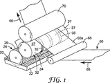
図1、2および3は、コーティング流体パターンを画定し、そしてそのパターンを移動ウェブへと選択的に適用するための装置およびプロセスを図式的に例示する。コーティング流体20は、パン22または他の適切な供給手段(例えば密閉ドクターブレードシステム)から回転供給ロール24へと供給される。コーティング流体20は供給ロール24の移動表面26によって拾い上げられ、そして供給ロール24と、軸方向に平行に回転するアプリケーターロール32との間に画定されたニップ30(図2を参照のこと)に運ばれる。図1および3に示されるように、アプリケーターロール32は、その上に1つ以上の長手方向に延在する周方向のらせん状の溝部分35を含む周方向の表面34を有する。各溝部分35はアプリケーターロール表面34の周囲に完全に延在し、そしてらせん状の溝36(図3Aを参照のこと)によって画定され、そして溝部分35ではないアプリケーターロール表面34の部分は、周方向の長手方向に延在する平滑表面部分37として形成される。ニップ30において、コーティング流体は供給ロール表面26からアプリケーターロール表面34へと転写される。供給ロール24およびアプリケーターロール32は、それぞれの表面26および34がニップ30の方へ移動するように回転し、そしてニップ30において表面間でわずかな間隙(例えば2ミル〜約10ミル)を有するように整列される。
1, 2 and 3 schematically illustrate an apparatus and process for defining a coating fluid pattern and selectively applying the pattern to a moving web. The
図3に示されるように、コーティング流体20aの層は、ニップ後のアプリケーターロール表面34a上に生じ、そしてその表面34aの全操作領域にわたって均一に配置される。また図3において、アプリケーターロール表面34のトポグラフィーは3つの溝部分35を含んでなるものとして例示され、これは、従って、所望のコーティング流体転写トポグラフィーを画定するために役立つが(例えば、各溝部分35はらせん状の溝36から形成される);単一の溝部分またはいずれかの複数の間隔をあけられた溝部分がコーティング流体転写(およびコーティング流体ストライプ形成)のために所望のトポグラフィーを提供してもよい。
As shown in FIG. 3, a layer of
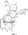
図2および3に示されるように、ドクターブレード40はニップ後のアプリケーターロール表面34aと係合する。ドクターブレード40は、アプリケーターロール表面34aと係合する直線状の操作スクラッピング縁41を有するリバースドクターブレードである。ドクターブレード40は、溝部分35を除き、アプリケーターロール表面34からコーティング流体20aを有効に削り取る。言い換えると、アプリケーターロール表面34の各平滑部分37のコーティング流体20aが削り取られる。各溝部分35の溝部分35のらせん状の溝36は、ドクターブレード40の操作スクラッピング縁41下を通過することによってアプリケーターロール32上にいくらかのコーティング流体が残存することを可能にする。ドクターブレード40を通過した後、アプリケーターロール表面34上に残存することを可能にするコーティング流体は、従って、その溝部分35内にのみ存在する。溝部分35自体は、アプリケーターロール32上で、特にドクターブレード後のアプリケーターロール表面34b上で残存するコーティング流体20aのパターン46を画定する。図3に例示されるように、各溝部分35は、それがドクターブレード40を越えて移動する時に、アプリケーターロール32の表面34上で残存する測定されたコーティング流体20aのストライプ48を画定する。アプリケーターロール表面34の平滑部分37のコーティング流体の削り取りに加えて、ドクターブレードの縁41は溝部分35に対して測定機能も果たし、それによって各溝部分35の溝36内でドクターブレード下をコーティング流体が通過することが可能である。
As shown in FIGS. 2 and 3, the
図2において、上部表面62と対立コーティング面64とを有するウェブ60(例えば、ペーパーシーティングまたはポリマーシーティング)は、矢印66の方向でアプリケーターロール32を通して移動する。ウェブ60は、アプリケーターロール表面32の移動方向に対して反対の方向で移動する。ウェブ60がアプリケーターロール32に隣接して横切る経路は、アイドラーロール68およびインプレッションロール70によって部分的に画定される。図2に示されるように、ウェブ60は、アプリケーターロール32の表面34とウェブ60との接触線の反対側のウェブ60の上部表面62上でいずれかの支持がない状態で、自由幅60aに沿ってアプリケーターロール32と接触する。このような接触線(図2中72として示される)において、ドクターブレード後のアプリケーターロール表面34b上のコーティング流体パターン46は、コーティング流体の相当するパターン74でウェブ60のコーティング面64上へと転写される(図3を参照のこと)。ウェブ60のパターン74は、アプリケーターロール32上で生じた各ストライプ48と一致するコーティング流体のストライプ78を含む。各ストライプ78は一般的に、ストライプ78の側面から側面へ、そしてストライプの長さに沿って、直線状の側縁および均一なコーティング重量を有する。ウェブコーティング面64の粗さが増加すると、ストライプ78の相対的な平滑性は向上する。コーティング流体が適用された後、次いで、コーティングされたウェブ60は、その上のコーティング流体のための乾燥または硬化ステーションへと前進し、次いでさらにそのウェブ経路に沿ってプロセスまたは変換ステーションへと前進する。従って、ウェブおよびアプリケーターロール表面の接触は、コーティング流体転写の目的のためのリバースキスとして画定される。
In FIG. 2, a web 60 (eg, a paper sheet or polymer sheet) having a
一実施形態において、接触線72は、約0.125インチ〜約0.25インチの幅を有する線(ウェブ移動方向で測定する場合)から構成され得る。図2に示されるように、接触線72(アプリケーターロール表面34とウェブ60のコーティング面64との間のリバースキス接触)と、ウェブ60の上部表面62とインプレッションロール70との接触線との間にウェブ60の短い幅がある。このようなリバースキスコーティング配列は、欧州特許第0847308号に開示される。より大きい幅の距離と対照的に、この短い幅は、ウェブへのコーティング流体の移動の間のより大きいウェブ安定性を保証し、これはその後、コーティング流体転写のダウンウェブおよびクロスウェブ均一性およびコーティング重量のような特徴の改善をもたらす。
In one embodiment,
加えて、ウェブ60へと転写されるコーティング流体のために望ましいコーティング重量を確立するための1つ手段は、アプリケーターロール表面34の速度とは異なる速度でウェブ60がアプリケーターロール接触線72を横切るようにすることによる。アプリケーターロール表面34は、ウェブ60のコーティング面64より0〜40%速い速度で移動し得るが、一実施形態において、20%超過速度関係が満足であることがわかっている。約30%〜約70%の範囲のアプリケーターロールからウェブへのコーティング流体の転写率が観測されるが、一実施形態において、60%転写率が満足であることがわかっている。供給ロール表面26はアプリケーターロール表面34とほぼ同じ表面速度で前進する。従って、供給ロールおよびアプリケーターロールの表面は、両方ともニップ30を通して互いに対してほぼ同じ速度で移動することができる。別の実施形態において、コーティング流体における発泡の影響を減少する手段として、供給ロール表面はアプリケーターロール表面速度より遅い速度で移動してもよい。
In addition, one means for establishing the desired coating weight for the coating fluid transferred to the
図1〜3Aに例示される上記流体コーティングシステムにおいて、アプリケーターロール32上でのストライプ48へのコーティング流体の初期測定は、アプリケーターロール表面34のトポグラフィーおよびドクターブレード40下のトポグラフィーの経路の相関関係となる。そのようにして測定されたコーティング流体は所望のパターン46の形状を仮定する。次いで、このパターンは、リバースキスコーティング操作においてアプリケーターロール32からウェブ60のコーティング面64上へとコーティング流体のパターン74として転写される。
In the fluid coating system illustrated in FIGS. 1-3A, the initial measurement of the coating fluid onto the
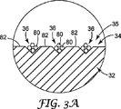
本発明のコーティングシステムと関連する使用に特に適応するコーティング流体は、ミクロスフィアをベースとする接着剤である。かかる接着剤は、約5ミクロン〜約200ミクロンの範囲の平均直径を有するミクロスフィアを有してよい。約40ミクロンの平均直径を有するミクロスフィアを有する接着剤が代表的である。本発明のコーティングシステムのために適切であると考えられるミクロスフィアをベースとする接着剤としては、米国特許第6,296,932号および同第5,571,617号に開示されるものが挙げられる。これらの接着性材料において、接着性ミクロスフィアは、所望の流体特性または接着特性を達成するために他の添加剤を含み得る水溶液中に懸濁される。図3Aに例示されるように、アプリケーターロール32のアプリケーターロール表面34に形成されたらせん状の溝36は、その中に1つ以上のミクロスフィア80を少なくとも部分的に受け取るように寸法設定される。図3Aに示される溝36はV形の溝であるが、溝が1つ以上のミクロスフィアをその中に受け取るために十分深い限り、他の溝形状(例えばU形の溝)も十分である。溝は、約50ミクロン〜約300ミクロンの深さ、およびV形の溝に関して、約15度〜約120度の歯角を有する(またはいくつかの実施形態において、約60程度〜約90程度の歯角が好ましい)。溝は、アプリケーターロール表面34を側方に(軸方向に)横切って測定される場合、1インチあたり約40個の溝〜1インチあたり約300個の間隔で配置される(いくつかの実施形態において、インチあたり約60個の溝〜1インチあたり約150個の溝が好ましい)。図3Aに示されるように、各らせん状の溝36の隣接部分間に陸82が提供される。一実施形態において、らせん状の溝36は、205ミクロンの開口幅で100ミクロンの深さを有し、そして陸80は、らせん状の溝36の隣接部分間に113ミクロンの幅を有する。らせん状の溝36は、アプリケーターロール32の軸に対して約80度〜約90度の角度で整列される。一実施形態において、らせん状の溝はその軸に対して約90度で整列される(例えば、89.95度)。
A coating fluid that is particularly adapted for use in connection with the coating system of the present invention is a microsphere-based adhesive. Such an adhesive may have a microsphere having an average diameter in the range of about 5 microns to about 200 microns. An adhesive having a microsphere having an average diameter of about 40 microns is typical. Microsphere-based adhesives that may be suitable for the coating system of the present invention include those disclosed in US Pat. Nos. 6,296,932 and 5,571,617. It is done. In these adhesive materials, the adhesive microspheres are suspended in an aqueous solution that may contain other additives to achieve the desired fluid or adhesive properties. As illustrated in FIG. 3A, the
表面トポグラフィーが、ミクロスフィアに損傷を与えることなくドクターブレードの操作スクラッピング縁下で、その中の1つ以上のミクロスフィアの通過を可能にするために十分深い表面特徴を含む限り、アプリケーターロール表面は別の表面トポグラフィー(らせん状の溝以外)を有してもよい。例えば、表面トポグラフィーは、測定の機能を行なうために複数の環状、平行な溝をアプリケーターロール表面上に含んでもよい。同様に、ミクロスフィア接着剤コーティング流体の測定機能を確立するために、表面トポグラフィーはアプリケーターロール表面上に複数のセル(例えば、スクリーンパターンで)を含んでもよい。 As long as the surface topography includes a surface feature deep enough to allow the passage of one or more microspheres under the operating scraping edge of the doctor blade without damaging the microspheres, the applicator roll The surface may have another surface topography (other than a spiral groove). For example, surface topography may include a plurality of annular, parallel grooves on the applicator roll surface to perform the measurement function. Similarly, the surface topography may include a plurality of cells (eg, in a screen pattern) on the applicator roll surface to establish the microsphere adhesive coating fluid measurement capability.
供給ロール表面は、コーティング流体をアプリケーターロール表面へと均一に運ぶために平滑である。供給ロール表面は、硬質(すなわち、非整合性)であってよく、またはウレタンゴムのような整合性材料から形成されてもよい。供給ロール表面を形成するために適切な他の代表的な材料としては、ステンレススチール、クロムメッキスチール、硬質プラスチックおよび研磨セラミックが挙げられる。 The supply roll surface is smooth to carry the coating fluid uniformly to the applicator roll surface. The supply roll surface may be hard (ie, inconsistent) or formed from a conformable material such as urethane rubber. Other representative materials suitable for forming the supply roll surface include stainless steel, chrome plated steel, hard plastics and abrasive ceramics.
アプリケーターロール表面は硬質(すなわち、非整合性)であり、そして一実施形態において、スチールロールのクロムメッキロール表面である。アプリケーターロール表面のための他の代表的な適切な材料としては、ステンレススチール、硬質プラスチックおよび研磨セラミックが挙げられる。上記の通り、ドクターブレード後のアプリケーターロール表面34b上へと配置されるコーティング流体のパターン46は、アプリケーターロール表面34の溝部分35によって画定される。図3中、等しい寸法の3個の溝部分35が例示され、それによってドクターブレード後のアプリケーターロール表面34b上に、ミクロスフィアを含有するコーティング流体の3本の等しい幅のストライプが画定される。ドクターブレード40の操作縁41によって、ドクターブレード後のアプリケーターロール表面34bのそれらの平滑部分37ではコーティング流体が除去される(ミクロスフィアをベースとする接着剤の水溶液の少量が平滑部分37上に残存するが、ミクロスフィアは存在しない)。そのようにしてアプリケーターロール表面34から削り取られたコーティング流体20aは供給ロール表面26上へ戻されて、次いでパン22中へと戻される。
The applicator roll surface is hard (ie, inconsistent), and in one embodiment is a chrome plated roll surface of a steel roll. Other representative suitable materials for the applicator roll surface include stainless steel, hard plastics and abrasive ceramics. As described above, the
コーティング流体パターン46は、その上に溝部分の異なる配列を有する別のアプリケーターロールによってアプリケーターロール32を置換することによって変更可能である。かかる別のアプリケーターロールは、単一溝部分のみ、またはいずれかの数の間隔をあけられた溝部分を有し得る。加えて、それらの溝部分は、同一アプリケーターロール上で同様の寸法(すなわち、幅)であっても、または異なる幅であってもよい。認識されるように、溝部分のいずれの所望のパターンもアプリケーターロール表面上に形成することが可能であり、これはドクターブレードによる通過後、従って、それはアプリケーターロール表面上(最終的にウェブ上)の所望のコーティング流体のパターンを画定する。
The
上記の通り、コーティング流体は、ドクターブレード40下での溝部分35の通過によるウェブ60への適用のために測定される。ドクターブレードの操作スクラッピング縁41は、アプリケーターロール表面34を横切って延在し、その平滑部分37およびその上の陸82と接触する(図3および3A)。アプリケーターロール32の表面特徴およびトポグラフィー(例えば、溝部分35の溝36)は、ドクターブレード40の縁41下で、その中の1つ以上のミクロスフィア80の通過を可能にするために十分深い。この関係は、ドクターブレード40を通過することが可能なミクロスフィア80の数を測定するための具体的手段を決定し、従って、アプリケーターロール表面34b上のストライプ48に存在するミクロスフィアを含有するコーティング流体の量を決定する。加えて、表面トポグラフィーを通して縁41を通過するミクロスフィア80は、それらが通過する時に損傷を与えられず、また剪断されない(いくらかのミクロスフィア圧縮は生じ得る)。溝(または他の適切なトポグラフィー特徴)は、ミクロスフィアがドクターブレードの通過のために本質的に「ラインアップ」することを可能にし、そしてミクロスフィアの溝の相対的な寸法のため、アプリケーターロールがドクターブレードを通過して回転する時にのみ、多くのミクロスフィアが時間をかけて通過し得る。この配列に関して、ドクターブレード後のアプリケーターロール表面34b上のミクロスフィアの量の正確な測定が得られ、これによって、接着剤がアプリケーターロール32からウェブ60まで転写されると、ウェブ60上における接着剤の均一付着が導かれる。
As described above, the coating fluid is measured for application to the
ドクターブレード(または少なくともその操作縁)は、硬質アプリケーターロール表面34に対して削り取りをするように整列された硬質な材料から形成される。かかる代表的な材料としては、ステンレススチール、ポリエステル、セラミックコーティング材料および複合材料が挙げられる。溝部分35の溝36の縁によるドクターブレードの可能な引掻傷を最小化するため、操作縁をそこで接触させるように維持しながら、前後にアプリケーターロール表面を横切って移動するように、図3に例示されるように、矢印79の方向でドクターブレードを往復させてよい。
The doctor blade (or at least its operating edge) is formed from a hard material aligned to scrape against the hard
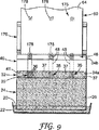
図2は、コーティング流体20のためのリサイクルおよび補充システム90の略図を含む。排水導管92は、パン22中で開口93から補充タンクアセンブリ94へと延在する。タンクアセンブリ94は、ウェブ60へのコーティング流体適用システムによって適用されたコーティング流体を補給するための追加的なコーティング流体を受け取るための手段を有する。タンクアセンブリ94は、パン22へとコーティング流体20を送り戻すために、アウトレット98へとインレット導管96を通してコーティング流体20をポンピングするためのポンプを含む。タンクアセンブリ94は、コーティング流体20の粘度をモニターするための手段も含み得る。コーティング流体20が水溶液中に生じたミクロスフィアを含んでなる場合、「脱水」は、一部、水溶液の蒸発のため自発的に生じる。また、アプリケーターロールから削り取られたコーティング流体は、アプリケーターロールの表面上に水(すなわち、水溶液)の薄フィルムを残し、従って、コーティング流体を脱水する。加えて、溝およびドクターブレードによって達成された測定は、未測定の転写よりも、より低いパーセントの固体(すなわち、ミクロスフィア)がアプリケーターロールからウェブへと転写されるため、アプリケーターロールから削り取られて、再利用のためにパンに戻される接着剤の固体性(および粘度)は高い。パン22に送達される接着剤の粘度はモニターされ、そして脱水のため必要である場合、所望の粘度レベルを維持するために追加の水溶液が添加される。一実施形態において、粘度のモニターおよび調整機能は、カナダ、ケベック州、ブーシェルビルのペリフェラル アドバンスド デザイン インコーポレイテッド(Peripheral Advanced Design,Inc.,Boucherville,Quebec,Canada)から入手可能なインクスペック ジュニア(Inkspec Junior)粘度制御システムによって取り扱われる。図2に関してのみ示されるが、上記機能を実行するコーティング流体リサイクルおよび補充システム90は、本発明のコーティング適用システムのいずれの実施形態に提供されてもよいことは理解される。
FIG. 2 includes a schematic diagram of a recycling and
上記の通り、ウェブ60のコーティング面64は、ドクターブレード後のアプリケーターロール表面34bとの接触線72に沿ってコーティング流体を拾い上げる。しかしながら、発明のコーティングシステムによって、単にアプリケーターロール表面34に対してウェブ60のコーティング面64を解放することによって、移動ウェブ60に関してプロセスを「オフ」にすることは非常に簡単である。一実施形態において、これは、アプリケーターロール32から離れて回転しているインプレッションロール70を移動することによって達成される。図4は、ウェブ60をアプリケーターロール表面34から分離するためにアプリケーターロール32から十分な距離で離れて移動するアプリケーターロール70を(実線で)例示する。移動ウェブ60の自由幅60aは、いずれの接触線においてもアプリケーターロール表面34と係合しない経路に従い、それによって、アプリケーターロール32からウェブ60へのコーティング流体の移動は不可能となる。この分離された構成において、アプリケーターロール表面34上のコーティング流体のストライプ48はアプリケーターロール表面34上に残り、そしてアプリケーターロール32が回転するとニップ30に再び入る。コーティングプロセスを「オン」にすることが望ましい場合、自由幅60aが接触線72においてドクターブレード後のアプリケーターロール表面34bと再び接触するまで、インプレッションロール70をアプリケーターロール32の方へ移動させ(図4中、透視で示される)、それによって、所望のコーティング流体パターン74でウェブ60のコーティング面64上へのリバースキス転写によるコーティング流体の転写が開始される。図4に例示されるように、矢印100の方向でのインプレッションロール70の移動は、ウェブ60に対してコーティングプロセスを「オフ」および「オン」にするために有効である。
As described above, the
移動ウェブへのコーティング流体の適用を活性化および不活性化するための上記の単純な手段は、移動ウェブのために確立された印刷プロセスラインにおいて本発明のシステムを容易に適合させる。図5は、本発明のコーティングプロセスを含むウェブ印刷ラインを図式的に例示する。ウェブ供給101は、複数のウェブプロセスステーション105、107、109および111を通してコーティング経路に沿っての移動のために、ウェブ103を提供する。この代表的なプロセスにおいて、ウェブプロセスステーション105は、ウェブ103の一方に表示が適用される印刷ステーションである。印刷ステーション105は典型的にドライヤーを含むか、またはウェブがその後、直ちに乾燥ステーションを横切る。次いで、印刷されたウェブは本発明のコーティングステーション107へと前進し、そこで接着剤のようなコーティング流体のストライプ状パターンがウェブ103の一表面に適用される。これは、すでに印刷された表面またはウェブの反対側表面であってもよい。コーティングパターンを適用した後、次いでウェブは乾燥ステーション109へ前進し、そして必要に応じて適用されたコーティングを乾燥させるか、または硬化させる。次いで、ウェブ103はさらに変換ステーション111にさらに前進する。これは、追加的な印刷ステーション、切断またはトリミングステーション、およびウェブ材料のもう1つの層の適用(すなわち、接着剤ライナー)、または所望の最終製品を達成するための他のさらなるウェブ変換プロセスを含む。図5は、本発明の装置および方法を具体化するコーティンステーション107を含む可能なウェブ印刷ラインのあくまでも例示である。様々な実施形態において、ウェブの両側における印刷はコーティングステーション107の前で生じてもよく、または他の変換操作がコーティングステーション107の前に移動ウェブに適用されてもよい。同様に、ウェブの一方または両方の側におけるさらなる印刷、またはさらなる変換操作がコーティングステーション107のダウンウェブで生じ得る。加えて、すでにコーティングされたウェブの同じ側で、またはウェブの反対側でコーティング流体の第2のパターンをコーティングするため、本発明の装置および方法を具体化する第2のコーティングステーションを提供することができる。
The simple means described above for activating and deactivating the application of coating fluid to a moving web easily adapts the system of the present invention in a printing process line established for the moving web. FIG. 5 schematically illustrates a web printing line including the coating process of the present invention.
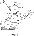
本明細書に記載の本発明のコーティングシステムおよび方法は、活性化される場合、ウェブにコーティング流体のストライプの連続的パターンを適用する(間断なく連続的ウェブに沿って)。いくつかの例において、ウェブの長さに沿ってコーティング流体を断続的に適用することが望ましい。これは、図6〜9に例示される様式で、インプレッションロールを変更し、そしてインプレッションロールとアプリケーターロールとの間の距離を制御することによって完成可能である。 The inventive coating systems and methods described herein, when activated, apply a continuous pattern of coating fluid stripes to the web (along the continuous web without interruption). In some instances, it is desirable to apply the coating fluid intermittently along the length of the web. This can be accomplished by changing the impression roll and controlling the distance between the impression roll and the applicator roll in the manner illustrated in FIGS.
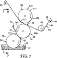
図1〜4に例示される実施形態において、インプレッションロール70は略平滑な円筒形の外部表面を有する。図6〜9に例示される部品は、インプレッションロールの外部表面の構成を除き、図1〜3に例示されるものと同一である。図6中、回転インプレッションロール170は、その周面174を長手方向に横切って(インプレッションロール170の軸に対して平行に)延在する1つ以上の隆起イメージパターンまたはカム172を有する。隆起イメージパターン172はアプリケーターロール表面34に係合しないが、インプレッションロール170の回転の間、ウェブ60のコーティング面64をアプリケーターロール表面34とのコーティング流体転写接触へと断続的に付勢するために役立つ。図7は、ウェブ60の自由幅60aがアイドラーロール68とインプレッションロール170上の隆起イメージパターン172の1つとの間で延在する時に、ウェブ60のコーティング面64がアプリケーターロール表面34と接触することを例示する。図8は、それがアイドラーロール68とインプレッションロール170の周面174との間で延在する時、ウェブ60の自由幅60aがアプリケーターロール表面34と接触しないことを例示する。隆起イメージパターン172がウェブ60の上部表面62と係合し、そしてそれをアプリケーターロール32の方へ押す時のみ(図7)、ウェブ60の自由幅60aは、接触線72としてドクターブレード後のアプリケーターロール表面34bと係合する。上記説明されたように、ドクターブレード後のアプリケーターロール表面34bはコーティング流体20aのパターン46(例えば、コーティング流体の1つ以上のストライプ48)を有する。このパターンは、ウェブ60の自由幅60aがドクターブレード後のアプリケーターロール表面34bと接触する時のみ、ウェブ60へと転写される(インプレッションロール170上の隆起イメージパターンまたはカム172とのウェブ60の断続的接触によって生じる)。従って、ウェブ60のコーティング面64に適用されるコーティング流体パターンはウェブの長さに沿って連続的でないが、コーティングパターン175として断続的に適用される(図9を参照のこと)。従って、図9に示されるように、コーティングパターン175は、ウェブ60のコーティング面64上で断続的に適用されたコーティング流体の短いストライプ178を含んでなる。認識できるように、隆起イメージパターンまたはカム172は、ウェブ60上でコーティング流体の断続的なストライプ178を画定するために様々な形態(例えば、ストライプ、円形、四角形等)を取ることが可能である。加えて、断続的なストライプ178は、ウェブ60上で印刷された(または印刷される)像とのレジストリで適用されてもよい。
In the embodiment illustrated in FIGS. 1-4, the
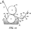
上記実施形態において、コーティング流体20は、供給ロール24によってアプリケーターロール表面34へと送達される。本発明のコーティング装置および方法の別の実施形態において、アプリケーターロール表面にコーティング流体を送達するための他の配列が可能である。例えば、図10に示されるように、その一部分がアプリケーターロール32下でパン22内のコーティング流体20と接触するように、アプリケーターロール32自体が回転してもよい。従って、供給ロールが提供されず;むしろ、アプリケーターロール32が下のパン22からコーティング流体20を拾い上げ、これは次いで、ドクターブレード40と接触することによって処理される(すなわち、アプリケーターロール表面上でストライプに測定される)。図10に例示される配列はより単純であり(供給ロールを必要としない)、そしてコーティング流体の発泡を減少し得るが、隣接するロール間のニップを通してコーティング流体を強制する作用は、有用な目的を果たし得る。ドクターブレードと係合する前にニップを通してコーティング流体を流すことは、溝の中に同伴される気泡の可能性を減少するために有益であり、従って、より均一なコーティングが形成される。
In the above embodiment, the
コーティング流体20をアプリケーターロール32の表面34へと送達するための図10の装置およびプロセスは上記実施形態とは異なるが、アプリケーターロール表面34のトポグラフィー(例えば、溝部分35)およびドクターブレード40を通してのコーティング流体の測定は、ドクターブレード後のアプリケーターロール表面34b上でのコーティング流体の均一な付着を達成するために有益である。トポグラフィー(例えば、溝部分35および平滑部分37)の配列は、ドクターブレード後のアプリケーターロール表面34b上でのコーティング流体ストライプの所望のパターンを画定するために有益である。そのパターンは、それがウェブ60の自由幅60aに沿って画定される接触線72でウェブ60へ転写されるまで、アプリケーターロール32によって運ばれる。コーティング流体のストライプは、リバースキスコーティング適用において、上記される様式でウェブ60のコーティング面64に転写される。
The apparatus and process of FIG. 10 for delivering the
好ましい実施形態に関して本発明が記載されたが、当業者は、本発明の精神および範囲から逸脱することなく、形式および詳細の変更があってもよいことを認識するであろう。全ての刊行物および特許は、個々の刊行物または特許が具体的に個々に援用されるように示されるように、本明細書に援用される。また2004年12月30日出願の「コーティング流体パターンの形成方法および装置(Method and Apparatus of Forming a Coating Fluid Pattern)」と題された同時譲渡米国特許出願第11/027,511号明細書(代理人整理番号60013US002)も本明細書に援用される。 Although the invention has been described with reference to preferred embodiments, those skilled in the art will recognize that changes may be made in form and detail without departing from the spirit and scope of the invention. All publications and patents are incorporated herein by reference so that individual publications or patents are specifically indicated to be individually incorporated. Also, co-assigned US patent application Ser. No. 11 / 027,511 entitled “Method and Apparatus of Forming a Coating Fluid Pattern” filed Dec. 30, 2004 (Method of Apparatus of Forming a Coating Fluid Pattern). Human reference number 60013US002) is also incorporated herein.
Claims (2)
アプリケーターロール表面のトポグラフィーが、コーティング流体のミクロスフィアを少なくとも部分的に受け入れるように寸法設定された長手方向に延びる少なくとも1つの周方向らせん状溝部分と、長手方向に延びる少なくとも1つの周方向平滑表面部分とを含んでなる該アプリケーターロール表面に、該ミクロスフィアを含有する該コーティング流体を導入することと、
前記アプリケーターロール表面にドクターブレードを係合させて、前記アプリケーターロール表面の前記平滑表面部分から前記コーティング流体を除去するとともに、前記アプリケーターロール表面の前記らせん状溝部分により、該ドクターブレードを通過して前進する前記ミクロスフィアの量を制限し、前記ミクロスフィアを含有する前記コーティング流体のパターンを、該パターンが前記らせん状溝部分によって画定され、かつ前記ミクロスフィアを含有する前記コーティング流体の少なくとも1つのストライプを画定するべく該パターンが形成されるように、前記アプリケーターロール表面に残存させることと、
前記コーティング流体の前記パターンを、前記アプリケーターロール表面から、リバースキス方式で前記アプリケーターロール表面に係合する移動ウェブのコーティング面に転写することと、
を含む方法。A method of forming a pattern of coating fluid on a surface, comprising:
The topography of the applicator roll surface has at least one circumferentially extending helical groove portion dimensioned to at least partially receive the coating fluid microspheres and at least one circumferentially smoothened longitudinally extending portion. Introducing the coating fluid containing the microspheres to the applicator roll surface comprising a surface portion;
A doctor blade is engaged with the applicator roll surface to remove the coating fluid from the smooth surface portion of the applicator roll surface and through the doctor blade by the helical groove portion of the applicator roll surface. Limiting the amount of the microspheres to advance, the pattern of the coating fluid containing the microspheres is defined by at least one of the coating fluids, wherein the pattern is defined by the helical groove portion and containing the microspheres Leaving the applicator roll surface such that the pattern is formed to define stripes;
Transferring the pattern of the coating fluid from the applicator roll surface to a coating surface of a moving web that engages the applicator roll surface in a reverse kiss manner;
Including methods.
長手方向範囲を有する回転する供給ロール表面に、ミクロスフィアを含有するコーティング流体を塗布することと、
アプリケーターロール表面のトポグラフィーが、前記コーティング流体の前記ミクロスフィアを受け入れる形状を有する長手方向に延びる少なくとも1つの周方向らせん状溝部分と、長手方向に延びる少なくとも1つの周方向平滑表面部分とを含んでなる、長手方向範囲を有する回転する該アプリケーターロール表面に、前記コーティング流体を前記供給ロール表面から転写することと、
前記アプリケーターロール表面に直線状ドクターブレード縁を係合させて、前記アプリケーターロール表面の前記平滑表面部分から前記コーティング流体を除去するとともに、前記アプリケーターロール表面の前記らせん状溝部分により、該ドクターブレード縁を通過して前進する前記ミクロスフィアの量を制限し、前記ミクロスフィアを含有する前記コーティング流体のパターンを、該パターンが前記らせん状溝部分によって画定され、かつ前記ミクロスフィアを含有する前記コーティング流体の少なくとも1つのストライプを画定するべく該パターンが形成されるように、前記アプリケーターロール表面に残存させることと、
前記ミクロスフィアを含有する前記コーティング流体の前記ストライプを、前記アプリケーターロール表面から、リバースキス方式で前記アプリケーターロール表面に係合する移動ウェブのコーティング面に転写することと、
を含む方法。A method of applying a coating fluid containing microspheres onto a moving web having a coating surface and a back surface opposite the coating surface,
Applying a coating fluid containing microspheres to a rotating supply roll surface having a longitudinal extent;
The topography of the applicator roll surface includes at least one longitudinally extending helical groove portion having a shape for receiving the microspheres of the coating fluid and at least one circumferentially smooth surface portion extending in the longitudinal direction. Transferring the coating fluid from the supply roll surface to the rotating applicator roll surface having a longitudinal extent comprising:
A linear doctor blade edge is engaged with the applicator roll surface to remove the coating fluid from the smooth surface portion of the applicator roll surface, and the helical blade portion of the applicator roll surface causes the doctor blade edge to Limiting the amount of the microspheres that advance through the coating fluid pattern containing the microspheres, the coating fluid containing the microspheres, the pattern being defined by the helical groove portion Leaving the applicator roll surface such that the pattern is formed to define at least one stripe of
Transferring the stripe of the coating fluid containing the microspheres from the applicator roll surface to the coating surface of a moving web that engages the applicator roll surface in a reverse kiss manner ;
Including methods.
Applications Claiming Priority (3)
| Application Number | Priority Date | Filing Date | Title |
|---|---|---|---|
| US11/027,542 US7625605B2 (en) | 2004-12-30 | 2004-12-30 | Method for coating a surface with a pattern of coating fluid |
| US11/027,542 | 2004-12-30 | ||
| PCT/US2005/042946 WO2006073615A1 (en) | 2004-12-30 | 2005-11-29 | Method for defining a coating fluid pattern |
Publications (3)
| Publication Number | Publication Date |
|---|---|
| JP2008526476A JP2008526476A (en) | 2008-07-24 |
| JP2008526476A5 JP2008526476A5 (en) | 2009-01-15 |
| JP5154948B2 true JP5154948B2 (en) | 2013-02-27 |
Family
ID=36086903
Family Applications (1)
| Application Number | Title | Priority Date | Filing Date |
|---|---|---|---|
| JP2007549378A Expired - Fee Related JP5154948B2 (en) | 2004-12-30 | 2005-11-29 | Method for defining coating fluid pattern |
Country Status (8)
| Country | Link |
|---|---|
| US (1) | US7625605B2 (en) |
| EP (1) | EP1830969B1 (en) |
| JP (1) | JP5154948B2 (en) |
| KR (1) | KR101251680B1 (en) |
| CN (1) | CN101094730B (en) |
| AT (1) | ATE466666T1 (en) |
| DE (1) | DE602005021154D1 (en) |
| WO (1) | WO2006073615A1 (en) |
Families Citing this family (31)
| Publication number | Priority date | Publication date | Assignee | Title |
|---|---|---|---|---|
| DE102007039949B3 (en) * | 2007-08-23 | 2008-12-04 | Flooring Technologies Ltd. | Device for applying a suspension to a carrier plate |
| US7925192B2 (en) * | 2007-09-04 | 2011-04-12 | Ricoh Company, Ltd. | Developing roller, developing device, process cartridge, and image forming apparatus |
| CN101503869B (en) * | 2008-02-05 | 2010-12-15 | 伟盟工业股份有限公司 | Biodegradable waterproof composite paper and its making process |
| JP5347527B2 (en) * | 2008-05-23 | 2013-11-20 | 株式会社リコー | Image forming device, foam coating device |
| JP4820427B2 (en) * | 2009-03-25 | 2011-11-24 | 富士機械工業株式会社 | Coating equipment |
| EP2444165B1 (en) * | 2009-06-18 | 2016-10-19 | Konica Minolta Holdings, Inc. | Coating method |
| CN101722128B (en) * | 2009-11-27 | 2011-12-21 | 东莞市华立实业股份有限公司 | Novel flat plate edge sealing strip back coating treatment equipment |
| JP5596721B2 (en) * | 2012-02-23 | 2014-09-24 | 尾池工業株式会社 | Method for producing conductive polymer resin film |
| US9295590B2 (en) | 2012-11-27 | 2016-03-29 | The Procter & Gamble Company | Method and apparatus for applying an elastic material to a moving substrate in a curved path |
| US9265672B2 (en) | 2012-11-27 | 2016-02-23 | The Procter & Gamble Company | Methods and apparatus for applying adhesives in patterns to an advancing substrate |
| US9248054B2 (en) | 2012-11-27 | 2016-02-02 | The Procter & Gamble Company | Methods and apparatus for making elastic laminates |
| CN103143476B (en) * | 2013-03-07 | 2016-03-02 | 金红叶纸业集团有限公司 | Coating device and coating method |
| JP5971157B2 (en) * | 2013-03-11 | 2016-08-17 | Jfeスチール株式会社 | Coating apparatus and coating method |
| IN2013MU01209A (en) * | 2013-03-28 | 2015-04-10 | Tata Consultancy Services Ltd | |
| GB2531035A (en) * | 2014-10-08 | 2016-04-13 | British American Tobacco Investments Ltd | Adhesive transfer system |
| GB201509080D0 (en) | 2015-05-27 | 2015-07-08 | Landa Labs 2012 Ltd | Coating apparatus |
| SE539739C2 (en) * | 2015-09-17 | 2017-11-14 | Ikea Supply Ag | A method of and a selective strip coating apparatus for applying a coating to one face of a selected first sub-group of parallel strips |
| EP3266933B1 (en) * | 2016-07-08 | 2024-09-18 | Lucart Spa | Paper material, apparatus and method for its production |
| CN106216165A (en) * | 2016-08-29 | 2016-12-14 | 贵州苗仁堂制药有限责任公司 | Babu cream coated and molded machine |
| CN106216164A (en) * | 2016-08-29 | 2016-12-14 | 贵州苗仁堂制药有限责任公司 | A kind of applicator roll |
| WO2018091087A1 (en) * | 2016-11-16 | 2018-05-24 | Sca Hygiene Products Ab | Apparatus and method for coating a web of absorbent substrate |
| CN107287567B (en) * | 2017-07-11 | 2019-09-27 | 成都天府新区河川科技有限公司 | Droplet ion sputtering technique and hydraulic turbine preparation method |
| US11707548B2 (en) | 2018-10-09 | 2023-07-25 | The Procter & Gamble Company | Absorbent article comprising a lotion resistant polymeric filler composition |
| CN113613796A (en) * | 2019-01-31 | 2021-11-05 | 陶氏环球技术有限责任公司 | Paint roller finish for multi-color paint, method of uniformly applying multi-color paint, and method of quantifying paint application uniformity |
| DE102019106642A1 (en) * | 2019-03-15 | 2020-09-17 | Homag Gmbh | Device for removing hot melt adhesive |
| CN111546699A (en) * | 2020-04-26 | 2020-08-18 | 佛山市达肯包装机械有限公司 | Longitudinal strip glue mechanism of paper tube bag tube making machine |
| KR102925846B1 (en) * | 2020-10-30 | 2026-02-09 | 주식회사 엘지에너지솔루션 | Apparatus of manufacturing electrode and method of manufacturing electrode |
| CN112642641A (en) * | 2020-12-28 | 2021-04-13 | 南京万博鼎成新材料科技有限公司 | Dull and stereotyped application is stayed limit device |
| WO2023057796A1 (en) * | 2021-10-07 | 2023-04-13 | Arcelormittal | Process and apparatus for manufacturing a steel strip for electrical applications |
| CN115946447A (en) * | 2022-12-28 | 2023-04-11 | 汕头市远生实业有限公司 | An energy-saving and quick-drying varnish structure |
| CN119702329B (en) * | 2024-12-31 | 2025-11-11 | 浙江墙煌新材料有限公司 | Color-light-resistant metal color-coated plate and roller coating processing system thereof |
Family Cites Families (31)
| Publication number | Priority date | Publication date | Assignee | Title |
|---|---|---|---|---|
| US3552353A (en) | 1966-12-05 | 1971-01-05 | Raymond A Labombarde | Apparatus for applying high viscosity coatings |
| US3691140A (en) | 1970-03-09 | 1972-09-12 | Spencer Ferguson Silver | Acrylate copolymer microspheres |
| GB1337345A (en) | 1970-11-30 | 1973-11-14 | Fuji Photo Film Co Ltd | Producing capsule-coated sheets |
| US3857731A (en) | 1973-04-06 | 1974-12-31 | Minnesota Mining & Mfg | Acrylate microsphere-surfaced sheet material |
| US4268597A (en) * | 1976-04-13 | 1981-05-19 | Philip A. Hunt Chemical Corp. | Method, apparatus and compositions for liquid development of electrostatic images |
| US4166152B1 (en) | 1977-08-17 | 1999-05-18 | Minnesota Mining & Mfg | Tacky polymeric microspheres |
| DE3069519D1 (en) * | 1979-12-11 | 1984-11-29 | Crosfield Electronics Ltd | Correction of gravure printing members |
| US4404243A (en) * | 1982-08-03 | 1983-09-13 | Reeves Bros., Inc. | Latent pressure-sensitive sheet material and method of making same using solvent-based pressure-sensitive adhesive |
| US4468418A (en) * | 1983-02-07 | 1984-08-28 | The Louis G. Freeman Company | Process for applying thermoplastic adhesive to flexible die-cut parts |
| US4495318A (en) | 1984-03-21 | 1985-01-22 | International Cube Corporation | Low tack microsphere glue |
| US4839416A (en) * | 1987-06-09 | 1989-06-13 | Ampad Corporation | Low tack microsphere adhesive |
| US5045569A (en) | 1988-11-30 | 1991-09-03 | Minnesota Mining And Manufacturing Company | Hollow acrylate polymer microspheres |
| JPH0312267A (en) * | 1989-06-09 | 1991-01-21 | Nordson Kk | Pattern coating method of hot melt type adhesive |
| US5340611A (en) | 1989-07-25 | 1994-08-23 | J. M. Voith Gmbh | Process for coating travelling webs |
| DE3927365A1 (en) | 1989-08-19 | 1991-02-21 | Hans Amoser | Applicator roller for coating low viscosity adhesive on foil - carries specified intersecting spiral grooves on its surface |
| JP2616999B2 (en) * | 1989-09-01 | 1997-06-04 | ユニ・チャーム株式会社 | Worn article |
| DE4029896A1 (en) * | 1989-12-02 | 1991-06-06 | Beiersdorf Ag | STRAPLESS DOUBLE-SIDED ADHESIVE TAPE |
| US5571617A (en) | 1993-04-23 | 1996-11-05 | Minnesota Mining And Manufacturing Company | Pressure sensitive adhesive comprising tacky surface active microspheres |
| US6517900B1 (en) | 1994-08-17 | 2003-02-11 | 3M Innovative Properties Company | Apparatus and method for applying coating materials to individual sheet members |
| US5447747A (en) | 1994-08-22 | 1995-09-05 | Minnesota Mining And Manufacturing Company | Method and apparatus for smoothing gravure coatings in the manufacture of magnetic recording tape |
| DE19511050A1 (en) | 1995-03-25 | 1996-09-26 | Voith Sulzer Papiermasch Gmbh | Method and device for producing a paper web having a CF layer |
| WO1997007899A1 (en) | 1995-08-31 | 1997-03-06 | Minnesota Mining And Manufacturing Company | Reverse gravure kiss coating system with output roller |
| US5714237A (en) | 1996-01-16 | 1998-02-03 | Minnesota Mining Manufacturing Company | Partially crosslinked microspheres |
| US5824748A (en) | 1996-06-03 | 1998-10-20 | Minnesota Mining And Manufacturing Company | Composite pressure sensitive adhesive microspheres |
| US5756625A (en) | 1996-10-11 | 1998-05-26 | Minnesota Mining And Manufacturing Company | Stabilized adhesive microspheres |
| JP3070565B2 (en) * | 1998-01-21 | 2000-07-31 | 松下電器産業株式会社 | Application method |
| US6531027B1 (en) * | 1998-08-03 | 2003-03-11 | The Procter & Gamble Company | Adhesive printing process for disposable absorbent articles |
| US6296932B1 (en) | 1998-12-14 | 2001-10-02 | 3M Innovative Properties Company | Microsphere adhesive coated article for use with coated papers |
| US6692819B1 (en) * | 1999-01-07 | 2004-02-17 | The Standard Register Company | Method of transparentizing a cellulose substrate |
| ATE458554T1 (en) * | 2001-06-02 | 2010-03-15 | Procter & Gamble | METHOD FOR PRINTING ACTIVE INGREDIENTS ON AN ARTICLE |
| US20030109630A1 (en) * | 2001-10-23 | 2003-06-12 | Smith Dawn E. | Microsphere adhesive formulations |
-
2004
- 2004-12-30 US US11/027,542 patent/US7625605B2/en not_active Expired - Fee Related
-
2005
- 2005-11-29 JP JP2007549378A patent/JP5154948B2/en not_active Expired - Fee Related
- 2005-11-29 EP EP05825813A patent/EP1830969B1/en not_active Expired - Lifetime
- 2005-11-29 CN CN2005800456615A patent/CN101094730B/en not_active Expired - Fee Related
- 2005-11-29 DE DE602005021154T patent/DE602005021154D1/en not_active Expired - Lifetime
- 2005-11-29 KR KR1020077017367A patent/KR101251680B1/en not_active Expired - Fee Related
- 2005-11-29 WO PCT/US2005/042946 patent/WO2006073615A1/en not_active Ceased
- 2005-11-29 AT AT05825813T patent/ATE466666T1/en not_active IP Right Cessation
Also Published As
| Publication number | Publication date |
|---|---|
| WO2006073615A1 (en) | 2006-07-13 |
| JP2008526476A (en) | 2008-07-24 |
| KR101251680B1 (en) | 2013-04-05 |
| US7625605B2 (en) | 2009-12-01 |
| EP1830969A1 (en) | 2007-09-12 |
| CN101094730A (en) | 2007-12-26 |
| KR20070097554A (en) | 2007-10-04 |
| ATE466666T1 (en) | 2010-05-15 |
| DE602005021154D1 (en) | 2010-06-17 |
| EP1830969B1 (en) | 2010-05-05 |
| US20060147637A1 (en) | 2006-07-06 |
| CN101094730B (en) | 2011-12-28 |
Similar Documents
| Publication | Publication Date | Title |
|---|---|---|
| JP5154948B2 (en) | Method for defining coating fluid pattern | |
| US20060147636A1 (en) | Method and apparatus of forming a coating fluid pattern | |
| EP0453427B1 (en) | Method for limitation of the width of coating in coating of paper or board and a device intended for carrying out the method | |
| CN106794484B (en) | Slurry coating device and slurry coating method | |
| US7144478B1 (en) | Pollution control method for cylindrical dryer used in paper machine | |
| JP2693441B2 (en) | Coating device | |
| EP0839584A2 (en) | Improved apparatus and method for applying a viscous liquid to a material surface | |
| EP1108538B1 (en) | Apparatus for coating a web | |
| JP4093330B2 (en) | Method and apparatus for continuous coating of strip material | |
| CN206688959U (en) | A kind of roll coater for eliminating sheet material roll marks | |
| KR20010075378A (en) | Pollution prevention method for cylindrical dryer used in paper machine | |
| JPH0427462A (en) | Coating method and applicator | |
| JP4397071B2 (en) | Rod for coating equipment | |
| JPH073698A (en) | Equipment and method of coating upper section of fibrous material web with color paint | |
| JP2003190855A (en) | Gravure coating apparatus | |
| JP2003170112A (en) | Coating method and apparatus | |
| JP2667033B2 (en) | Roller curtain coating method | |
| JP2004188331A (en) | Kiss type reverse roll coater | |
| JPH02180662A (en) | Roll coater | |
| GB1600616A (en) | Coating sheet material with liquids | |
| JP4531924B2 (en) | Method and apparatus for applying viscous liquid to perforated thin plate | |
| JP2003236436A (en) | Coating device | |
| JPH0531439A (en) | Coating method | |
| JPH02293068A (en) | Coating device | |
| JPH04244264A (en) | Application method |
Legal Events
| Date | Code | Title | Description |
|---|---|---|---|
| A521 | Request for written amendment filed |
Free format text: JAPANESE INTERMEDIATE CODE: A523 Effective date: 20081120 |
|
| A621 | Written request for application examination |
Free format text: JAPANESE INTERMEDIATE CODE: A621 Effective date: 20081120 |
|
| A977 | Report on retrieval |
Free format text: JAPANESE INTERMEDIATE CODE: A971007 Effective date: 20110725 |
|
| A131 | Notification of reasons for refusal |
Free format text: JAPANESE INTERMEDIATE CODE: A131 Effective date: 20110802 |
|
| A601 | Written request for extension of time |
Free format text: JAPANESE INTERMEDIATE CODE: A601 Effective date: 20111101 |
|
| A602 | Written permission of extension of time |
Free format text: JAPANESE INTERMEDIATE CODE: A602 Effective date: 20111109 |
|
| A521 | Request for written amendment filed |
Free format text: JAPANESE INTERMEDIATE CODE: A523 Effective date: 20120202 |
|
| TRDD | Decision of grant or rejection written | ||
| A01 | Written decision to grant a patent or to grant a registration (utility model) |
Free format text: JAPANESE INTERMEDIATE CODE: A01 Effective date: 20121106 |
|
| A61 | First payment of annual fees (during grant procedure) |
Free format text: JAPANESE INTERMEDIATE CODE: A61 Effective date: 20121206 |
|
| FPAY | Renewal fee payment (event date is renewal date of database) |
Free format text: PAYMENT UNTIL: 20151214 Year of fee payment: 3 |
|
| R150 | Certificate of patent or registration of utility model |
Ref document number: 5154948 Country of ref document: JP Free format text: JAPANESE INTERMEDIATE CODE: R150 Free format text: JAPANESE INTERMEDIATE CODE: R150 |
|
| R250 | Receipt of annual fees |
Free format text: JAPANESE INTERMEDIATE CODE: R250 |
|
| R250 | Receipt of annual fees |
Free format text: JAPANESE INTERMEDIATE CODE: R250 |
|
| R250 | Receipt of annual fees |
Free format text: JAPANESE INTERMEDIATE CODE: R250 |
|
| LAPS | Cancellation because of no payment of annual fees |