JP5154916B2 - Desorption device for pipe connecting member - Google Patents
Desorption device for pipe connecting member Download PDFInfo
- Publication number
- JP5154916B2 JP5154916B2 JP2007335102A JP2007335102A JP5154916B2 JP 5154916 B2 JP5154916 B2 JP 5154916B2 JP 2007335102 A JP2007335102 A JP 2007335102A JP 2007335102 A JP2007335102 A JP 2007335102A JP 5154916 B2 JP5154916 B2 JP 5154916B2
- Authority
- JP
- Japan
- Prior art keywords
- flange
- valve
- flanges
- branch
- pipe
- Prior art date
- Legal status (The legal status is an assumption and is not a legal conclusion. Google has not performed a legal analysis and makes no representation as to the accuracy of the status listed.)
- Active
Links
Images

Landscapes
- Details Of Valves (AREA)
Description
本発明は、既設流体管の分岐部と、この分岐部に接続された管接続部材との間に介在するフランジに弁体挿入部を外嵌して、この弁体挿入部によりフランジの対向面間に弁体を水密的に挿入し、管接続部材を脱着する管接続部材の脱着装置に関する。 According to the present invention, a valve body insertion portion is externally fitted to a flange interposed between a branch portion of an existing fluid pipe and a pipe connection member connected to the branch portion. The present invention relates to a pipe connecting member detaching apparatus for inserting a valve body in a watertight manner and detaching a pipe connecting member.
従来、既設流体管の分岐部にフランジ等を介して連結される例えば空気弁及び補修弁等の管接続部材を、交換あるいは保守点検等のために既設流体管に対して脱着する場合、管接続部材を既設流体管から外す際に水圧等で多量の管内流体が流出するため、その管接続部材が連結されている既設管の流体の流れを元から遮断し、そのフランジ同士を連結しているボルトを挿脱して管接続部材を脱着していた。また、分岐部に接続された管接続部材を不断流状態で交換する場合には、密閉ケースによって分岐部を管接続部材も含めて外部から覆い、分岐部のフランジに密閉ケースの外からの操作で管接続部材を押圧するとともに、管接続部材を交換するために密閉ケース内を仕切る作業弁が用いられていた(例えば、特許文献1参照)。 Conventionally, when connecting or disconnecting pipe connection members such as air valves and repair valves to existing fluid pipes to existing branch pipes for maintenance or inspection, etc. When removing a member from an existing fluid pipe, a large amount of fluid in the pipe flows out due to water pressure or the like. Therefore, the fluid flow of the existing pipe to which the pipe connecting member is connected is blocked from the original, and the flanges are connected to each other. The pipe connecting member was removed by inserting and removing the bolt. In addition, when replacing the pipe connection member connected to the branch part in an uninterrupted state, the branch part including the pipe connection member is covered from the outside by a sealed case, and the operation of the branch part flange from the outside of the sealed case is performed. In order to press the pipe connecting member and to replace the pipe connecting member, a work valve that partitions the inside of the sealed case has been used (for example, see Patent Document 1).
しかしながら、特許文献1にあっては、分岐部及び管接続部材に対し比較的大きな密閉ケースを漏れのないように立設する必要があり、しかも分岐部のフランジの連結の解除を操作窓より行うので作業に熟練を要し、また密閉ケース用の作業弁を備えるため装置全体が大型化するという問題があった。 However, in Patent Document 1, it is necessary to erect a relatively large sealed case with respect to the branch portion and the pipe connecting member so as not to leak, and the connection of the flange of the branch portion is released from the operation window. Therefore, there is a problem that the work requires skill and the entire apparatus is enlarged because the work valve for the sealed case is provided.
本発明は、このような問題点に着目してなされたもので、脱着のための装置が大型化することなく容易に構築でき、しかも熟練を要することなく、不断流で管接続部材の脱着を行うことができる管接続部材の脱着装置を提供することを目的とする。 The present invention has been made paying attention to such problems, and can be easily constructed without increasing the size of the apparatus for detachment, and without requiring skill, the detachment of the pipe connecting member can be performed without a constant flow. It is an object of the present invention to provide a pipe connecting member detachable apparatus that can be used.
前記課題を解決するために、本発明の請求項1に記載の管接続部材の脱着装置は、
既設流体管の分岐部と、該分岐部に接続された管接続部材との間に介在するフランジに弁体挿入部を外嵌して、該弁体挿入部により前記フランジの対向面間に弁体を水密的に挿入し、管接続部材を脱着する管接続部材の脱着装置であって、
前記弁体挿入部には、前記分岐部側のフランジに対し支持された支持手段が設けられ、該支持手段は、前記分岐部側のフランジの周方向に沿って延設されて該フランジの上面に係止するために径方向の内方に向かって膨出して設けられている上面係止部と、前記分岐部側のフランジの下面に当接される下面当接部と、から成ることを特徴としている。
この特徴によれば、分岐部と管接続部材とのフランジを水密に外装する弁体挿入部を設けることにより、脱着装置が大型化することなく容易に構築できるばかりか、分岐部と管接続部材とのフランジ以外の部位を露呈させた状態で作業を行えるため、熟練を要することなく、不断流で管接続部材の脱着を行うことができ、かつ上面係止部と下面当接部とにより支持手段を容易に構成して、この支持手段によって分岐部側のフランジの両面を利用して弁体挿入部を分岐部に対して確実に支持することができる。また、上面係止部が分岐部側のフランジの周方向に沿って延設されることで、上面係止部が分岐部側のフランジの周方向全体に均一に係止されるようになり、弁体挿入部を安定的に支持することができる。
In order to solve the above-mentioned problem, a desorption device for a pipe connecting member according to claim 1 of the present invention provides
A valve element insertion portion is fitted on a flange interposed between a branch portion of an existing fluid pipe and a pipe connection member connected to the branch portion, and a valve is inserted between the opposing surfaces of the flange by the valve element insertion portion. A pipe connecting member detaching apparatus for inserting a body in a watertight manner and detaching a pipe connecting member,
The valve body insertion part is provided with support means supported by the flange on the branch part side, and the support means extends along the circumferential direction of the flange on the branch part side and is provided on the upper surface of the flange. An upper surface locking portion bulging inward in the radial direction for locking to the inner surface, and a lower surface abutting portion abutting against the lower surface of the flange on the branching portion side. It is a feature.
According to this feature, not only can the desorption device be easily constructed without increasing the size by providing the valve body insertion portion for watertightly covering the flange between the branch portion and the pipe connection member, but also the branch portion and the pipe connection member. Because the work can be performed in a state where the parts other than the flange are exposed, the pipe connecting member can be attached and detached without a need for skill, and supported by the upper surface locking part and the lower surface contact part. By configuring the means easily, it is possible to reliably support the valve body insertion portion with respect to the branch portion by using both surfaces of the flange on the branch portion side by this support means. Further, the upper surface locking portion is extended along the circumferential direction of the flange on the branching portion side, so that the upper surface locking portion is uniformly locked over the entire circumferential direction of the flange on the branching portion side, A valve body insertion part can be supported stably.
本発明の請求項2に記載の管接続部材の脱着装置は、請求項1に記載の管接続部材の脱着装置であって、
前記下面当接部によって前記分岐部側のフランジの下面を下方から押圧する押圧手段が設けられることを特徴としている。
この特徴によれば、押圧手段によって下面当接部を分岐部側のフランジの下面に押圧して、上面係止部と下面当接部とにより分岐部側のフランジを挟持して弁体挿入部を固定できる。
The pipe connecting member detaching apparatus according to
The lower surface contact portion is provided with pressing means for pressing the lower surface of the flange on the branching portion side from below.
According to this feature, the lower surface contact portion is pressed against the lower surface of the flange on the branching portion side by the pressing means, and the flange on the branching portion side is sandwiched between the upper surface locking portion and the lower surface contact portion, so that the valve body insertion portion Can be fixed.
本発明の請求項3に記載の管接続部材の脱着装置は、請求項1または2に記載の管接続部材の脱着装置であって、
前記支持手段の下面当接部は、前記弁体挿入部本体から延設された延設部に螺挿された螺挿ねじから成ることを特徴としている。
この特徴によれば、下面当接部である螺挿ねじを適宜螺挿して調整することで、フランジの上面に上面係止部を遊びしろ無くしっかりと係止させることができる。
The pipe connecting member detaching device according to claim 3 of the present invention is the pipe connecting member detaching device according to
The lower surface abutting portion of the support means is formed of a screw insertion screw that is screwed into an extending portion that extends from the valve body insertion portion main body.
According to this feature, the upper surface locking portion can be securely locked to the upper surface of the flange without any play by adjusting the screw insertion screw, which is the lower surface contact portion, by appropriately screwing in and adjusting.
本発明の実施例を以下に説明する。 Examples of the present invention will be described below.
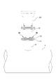
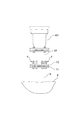
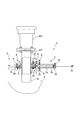
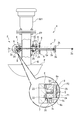
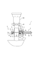
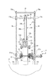
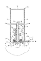
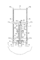
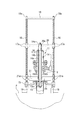
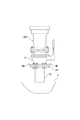
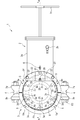
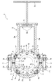
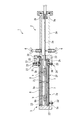
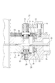
本発明の実施例を図面に基づいて説明すると、先ず図1は、本発明の実施例における管接続部材である空気弁及びフランジ短管が分岐部に取り付けられた状態を示す正面図である。図2は、作業用ボルト・ナットに取り換えた状態を示す正面図である。図3は、弁装置をフランジに設置した状態を示す一部断面図である。図4は、間隙形成手段によりフランジ間に間隙を形成した状態を示す一部断面図である。図5は、フランジ間に弁体を挿入した状態を示す一部断面図である。図6は、弁装置の上方に閉塞装置を設置した状態を示す一部断面図である。図7は、閉塞部材を分岐口に挿入して密封した状態を示す一部断面図である。図8は、弁装置及び収容ケースを撤去している状態を示す一部断面図である。図9は、弁装置及び収容ケースを撤去した状態を示す一部断面図である。図10は、補修弁及び収容ケースを取り付ける状態を示す一部断面図である。図11は、空気弁を取り付けた状態を示す一部断面図である。図12は、弁装置を示す平面図である。図13は、弁装置を示す横断平面図である。図14は、図12における弁装置を示すA−A縦断正面図である。図15は、第1及び第2挿通孔閉塞部を示す拡大縦断正面図である。 DESCRIPTION OF THE PREFERRED EMBODIMENTS An embodiment of the present invention will be described with reference to the drawings. First, FIG. 1 is a front view showing a state in which an air valve, which is a pipe connecting member in the embodiment of the present invention, and a short flange pipe are attached to a branch portion. FIG. 2 is a front view showing a state where the working bolts and nuts are replaced. FIG. 3 is a partial cross-sectional view showing a state in which the valve device is installed on the flange. FIG. 4 is a partial cross-sectional view showing a state in which a gap is formed between the flanges by the gap forming means. FIG. 5 is a partial cross-sectional view showing a state in which the valve body is inserted between the flanges. FIG. 6 is a partial cross-sectional view showing a state in which the closing device is installed above the valve device. FIG. 7 is a partial cross-sectional view showing a state where the closing member is inserted into the branch port and sealed. FIG. 8 is a partial cross-sectional view showing a state where the valve device and the housing case are removed. FIG. 9 is a partial cross-sectional view showing a state where the valve device and the housing case are removed. FIG. 10 is a partial cross-sectional view showing a state in which the repair valve and the housing case are attached. FIG. 11 is a partial cross-sectional view showing a state in which an air valve is attached. FIG. 12 is a plan view showing the valve device. FIG. 13 is a cross-sectional plan view showing the valve device. FIG. 14 is an AA longitudinal sectional front view showing the valve device in FIG. 12. FIG. 15 is an enlarged vertical front view showing the first and second insertion hole blocking portions.
図1に示されるように、既設流体管Pの管内を流れる水道水中の空気を管外に排出するために、あるいは管内が負圧にならないようにするために、既設流体管Pの所定箇所毎には、管接続部材としての空気弁AV1が設けられている。空気弁AV1は、既設流体管Pに設けられた分岐部Bと、分岐部BのフランジF1にフランジF2が接続された管接続部材としてのフランジ短管FPと、を介して既設流体管Pに取り付けられている。 As shown in FIG. 1, in order to discharge the air in the tap water flowing inside the existing fluid pipe P to the outside of the pipe or to prevent the inside of the pipe from becoming a negative pressure, every predetermined portion of the existing fluid pipe P is provided. Is provided with an air valve AV1 as a pipe connecting member. The air valve AV1 is connected to the existing fluid pipe P via a branch part B provided in the existing fluid pipe P and a flange short pipe FP as a pipe connecting member in which the flange F2 is connected to the flange F1 of the branch part B. It is attached.
通常は、図11に示されるように、空気弁の修理、調整時に分岐部Bからの流れを開閉操作する管接続部材としての補修弁Vが、既設流体管Pの分岐部Bに設けたフランジF1に取り付けられて、補修弁Vの上端にフランジを介して空気弁AV2が取り付けられている場合が多い。 Normally, as shown in FIG. 11, a repair valve V as a pipe connecting member that opens and closes the flow from the branch part B at the time of repair and adjustment of the air valve is a flange provided on the branch part B of the existing fluid pipe P. In many cases, the air valve AV2 is attached to the upper end of the repair valve V via a flange.
図1のように、補修弁Vが設けられていない空気弁AV1や、補修弁Vが設けられていてもその補修弁Vが故障等によって止水不良となった空気弁AV1を交換する必要が生じた場合に本発明の管接続部材の脱着装置が採用される。 As shown in FIG. 1, it is necessary to replace the air valve AV1 that is not provided with the repair valve V, or the air valve AV1 that is provided with the repair valve V and has the water stop failure due to failure or the like. When this occurs, the pipe connecting member detaching apparatus of the present invention is employed.
次に、管接続部材としての空気弁AV1の脱着を不断流で行う方法を説明する。まず、図1に示されるように、分岐部BのフランジF1及びフランジF1にボルト・ナットBN(接続ボルト)で接続されているフランジ短管FPのフランジF2を清掃し、フランジF1,F2の状態を確認する。パッキン等による止水に悪影響をもたらすような凹凸等があれば補修を行い、その後、ボルト・ナットBNを1本ずつフランジF1,F2より取り外し、作業用ボルト・ナット9に取り換え、図2に示されるように、ボルト・ナットBNを作業用ボルト・ナット9(接続ボルト)に交換する。
Next, a method for detaching and attaching the air valve AV1 as a pipe connecting member will be described. First, as shown in FIG. 1, the flange F2 of the flange short pipe FP connected to the flange F1 and the flange F1 of the branch portion B with bolts and nuts BN (connection bolts) is cleaned, and the states of the flanges F1 and F2 Confirm. If there are irregularities that have an adverse effect on water stoppage due to packing, etc., repair them. Then, remove bolts and nuts BN one by one from flanges F1 and F2 and replace them with working bolts and
尚、本実施例では、両フランジF1,F2のそれぞれに形成された6つのボルト挿通孔24,25に6本のボルト・ナットBNが挿設されることで、両フランジF1,F2が接続されている。ボルト・ナットBNを作業用ボルト・ナット9に交換する際には、6本のボルト・ナットBNを1本づつ取り外し、1本づつ作業用ボルト・ナット9と交換する。そして、6本のボルト・ナットBNのうち、5本を作業用ボルト・ナット9と交換する。
In this embodiment, the six flanges F1 and F2 are connected by inserting six bolts and nuts BN into the six
具体的には、後述する弁装置1の弁体2aが通過する部位に配置されたボルト挿通孔24,25には、作業用ボルト・ナット9を取り付けないようにして、作業用ボルト・ナット9の配置が弁体2aの通過を妨げないようにする(図13参照)。作業用ボルト・ナット9が取り付けられていないボルト挿通孔24,25は、後述するように、第1及び第2挿通孔閉塞部26,27によって閉塞される(図15参照)。
Specifically, the working bolts and
図4の部分拡大図に示すように、両フランジF1,F2を接続する5つの作業用ボルト・ナット9は、ナット9aと、ボルト9bと、ワッシャ9cとにより構成されている。ナット9aは、一端部が閉塞され他端部が開放されて内周面にボルト9bに対応する雌ネジが螺設されている六角柱に形成されている。また、ナット9a及びワッシャ9cには、鍔部が設けられ、フランジF1,F2に当接する面にパッキン溝(図示略)が刻まれ、このパッキン溝にパッキン(図示略)が収容されている。尚、ボルト9bは、ナット9aの雌ネジと対応する六角ボルトであり、フランジF1、フランジF2に所定の間隙をあけてもナット9aとネジ部が充分に噛み合う長さに設定されている。
As shown in the partially enlarged view of FIG. 4, the five working bolts and
作業用ボルト・ナット9に交換することによりナット9aのパッキンと、ワッシャ9cのパッキンとによりフランジのボルト挿通孔からの漏水が防止される。作業用ボルト・ナット9は、本実施例に限らず、ナット9aを通常のナットを使用してワッシャ9cを設けて止水してもよく、また、ボルトの頭部にパッキン溝を設けてパッキンを収容し止水してもよく、フランジのボルト挿通孔からの漏水を防止する構造のボルト・ナットであればよい。
By replacing the working bolt /
次に、図3に示すように、分岐部B側のフランジF1及びフランジ短管FP側のフランジF2の周方向に、弁収容部材2と取付部材3とに二分割された弁体挿入部としての弁装置1を外嵌して取り付ける。
Next, as shown in FIG. 3, as a valve body insertion portion that is divided into a
ここで、弁装置1の構成について、詳細に説明する。図3、図12〜15に示されるように、弁装置1の弁収容部材2は、下面を弾性体のシール部材で覆われた板状の弁体2aを分岐部Bのフランジの座Sで止水するように操作ハンドル2cの回転操作で進退可能に収容している矩形部2eと、フランジF1,F2の外径より若干大きめの内径の円弧状部2f(弁体挿入部本体)と、間隙形成部5により形成された所定の間隙に弁体2aを案内する弁体案内手段としての弁体案内部6と、フランジF1,F2を接続するボルト・ナットBNが取り外されたボルト挿通孔24,25を水密的に閉塞する挿通孔閉塞手段としての第1及び第2挿通孔閉塞部26,27と、を有している。
Here, the configuration of the valve device 1 will be described in detail. As shown in FIGS. 3 and 12 to 15, the
また、弁装置1の取付部材3は、円弧状部2fと同様に円弧状をなす円弧状部3aを有している。更に、弁収容部材2及び取付部材3には、円弧状部2f,3aより外側に突出して取付ボルト・ナット4を相通するボルト孔が設けられた掛止部2g,3bと、フランジF1,F2の対向面間に所定の間隙を形成する間隙形成手段としての間隙形成部5と、が設けられている。
Further, the attachment member 3 of the valve device 1 has an
尚、間隙形成部5は、円弧状部2fの適所に2箇所設けられているとともに、取付部材3の適所に2箇所設けられている。すなわち、間隙形成部5は、フランジF1,F2の周方向に沿って計4箇所設けられている。更に尚、弁収容部材2の円弧状部2fに設けられた第1及び第2挿通孔閉塞部26,27は、後述するように、円弧状部2fにおける弁体2aが通過する位置に対応して設けられている(図13参照)。
Two
また、円弧状部2fの下部には、フランジF1の下面に接離可能に螺挿された支持手段を構成する下面当接部としての螺挿ねじ2iが螺挿されたフランジ方向に突出するように延設された延設部2hがボルト・ナットBNの操作に影響しないように形成されている。また、円弧状部2fの内側周面には、フランジF1の外側周面に当接して止水する弾性体の第1止水パッキン7が周方向に沿って設けられているとともに、フランジF2の外側周面に当接して止水する弾性体の第2止水パッキン8が周方向に沿って設けられている(図14参照)。閉塞部
Further, a
尚、第1挿通孔閉塞部26は、円弧状部2fの下面側に設けられている。この第1挿通孔閉塞部26は、延設部2hと、この延設部2hに螺挿された螺挿ねじ28と、この螺挿ねじ28の上端に設けられた閉塞部30と、から成る。また、閉塞部30には、フランジF1に当接する面にパッキン溝が刻まれ、パッキンが収容されており、閉塞部30が、フランジF1のボルト挿通孔24を水密に閉塞するようになっている(図15参照)。
The first insertion
更に、第2挿通孔閉塞部27は、円弧状部2fにの上面側に設けられている。この第2挿通孔閉塞部27は、円弧状部2fの上面側に取付ボルト32により取り付けられる平面視で略半円形状をなす固定部33と、この固定部33に螺挿された螺挿ねじ29と、この螺挿ねじ29の下端に設けられた閉塞部31と、から成る。また、閉塞部31には、フランジF2に当接する面にパッキン溝が刻まれ、パッキンが収容されており、閉塞部31が、フランジF2のボルト挿通孔25を水密に閉塞するようになっている(図15参照)。尚、固定部33は、取付ボルト32によって円弧状部2fに対して着脱自在に取り付けられている。
Further, the second insertion
第2挿通孔閉塞部27の固定部33は、円弧状部2fからフランジF2の一部の上方位置まで延設されるようになっており、この固定部33における延設された部位に螺挿ねじ29が螺挿されている。尚、固定部33に螺挿された螺挿ねじ29が本実施例における移動手段となっており、後述するように、螺挿ねじ29を回転操作すると、閉塞部31がフランジF2の移動とともに移動するようになっている。また、第1及び第2挿通孔閉塞部26,27は、ボルト挿通孔24,25を閉塞しても、ボルト挿通孔24,25を貫通しない長さに形成されており、第1挿通孔閉塞部26の閉塞部30の先端と第2挿通孔閉塞部27の螺挿ねじ29の先端とが当接しないようになっている(図15参照)。
The fixing
尚、前述した円弧状部2fと同様に、取付部材3にも、フランジF1の外側周面に当接する第1止水パッキン7と、フランジF2の外側周面に当接する第2止水パッキン8とが設けられている。取付部材3の第1及び第2止水パッキン7,8は、弁収容部材2の円弧状部2fの第1及び第2止水パッキン7,8の端部同士が当接し合う長さに設けられている。
As with the arc-shaped
また、第1及び第2止水パッキン7,8は、弁収容部材2の円弧状部2f及び取付部材3の円弧状部3aの内周面に形成されたあり溝22,23に取り付けられている。そのため第1及び第2止水パッキン7,8は、弁収容部材2の円弧状部2f及び取付部材3の円弧状部3aのあり溝22,23から容易に脱着させることができ、第1及び第2止水パッキン7,8の交換作業を容易に行うことができる。
The first and second water-
また、弁収容部材2の円弧状部2fの内側周面に沿って、支持手段を構成する上面係止部2jが、径方向の内方に向かって膨出して設けられている。更に、矩形部2eの上面に、矩形部2e内部と開閉可能に連通する排水バルブ2bが設けられており、後述する弁体2aの挿入の際に、止水状態の確認ができるようになっている。
Further, along the inner peripheral surface of the arc-shaped
また、円弧状部3aの下部には、フランジ方向に突出するように延設された延設部3cがボルト・ナットBNの操作に影響しないように形成されている。更に、延設部3cには、フランジF1の下面に接離可能に螺挿された支持手段を構成する下面当接部としての螺挿ねじ3dが螺挿されている。
Further, an extending
更に、図14に示されるように、円弧状部3aの内側周面に沿って、支持手段を構成する上面係止部3eが、径方向の内方に向かって膨出して設けられている。すなわち、弁体挿入部としての弁装置1には、支持手段として、上面係止部2j、3eと下面当接部である螺挿ねじ2i、3dとが構成されており、支持手段、すなわち上面係止部2j、3e及び螺挿ねじ2i、3dが、分岐部B側のフランジF1に対し支持されている。ここで、支持手段が分岐部B側のフランジF1に対し支持されているとは、支持手段が、分岐部Bが設けられた既設流体管P側への下方の移動を拘束されていることを意味する。
Further, as shown in FIG. 14, along the inner peripheral surface of the arc-shaped
支持手段についてより詳しく説明すると、図12〜図14に示されるように、弁収容部材2及び取付部材3の内周面には、上下に配置された第1止水パッキン7と第2止水パッキン8との間に、周方向に沿って延設された上面係止部2j、3eが突設されている。この上面係止部2j、3eは、分岐部B側のフランジF1の上面に係止されるようになっている。
The support means will be described in more detail. As shown in FIGS. 12 to 14, the first water-
また、弁収容部材2及び取付部材3における第1止水パッキン7よりも下方位置から延設部2h,3cが延設されており、この延設部2h,3cに螺挿ねじ2i,3dが螺挿されている。そして、上面係止部2j、3eと螺挿ねじ2i,3dとで、分岐部B側のフランジF1を上下方向から挟持して、弁装置1をしっかりと支持するようになっている。
Further, extending
図13に示されるように、取付部材3に設けられた間隙形成部5は、円弧状部2fに螺挿されフランジF1,F2の対向方向と平行に進退可能な進退部5aと、この進退部5aの降下によりフランジの対向面を離間する方向に押圧する押圧部5bと、押圧部5bの下方において円弧状部3aに固設された支点部(図示略)と、よりなる。
As shown in FIG. 13, the
押圧部5bは、支点部(図示略)と当接する地点を支点とするとともに、前述した進退部5aの下方への前進により当接する地点を力点として、フランジF2の下面と当接する地点を作用点とし、梃子の原理を利用して、フランジF1,F2の対向面を互いに離間する方向に押圧する。
The
図4に示されるように、弁体案内部6は、フランジF1,F2の近傍において、フランジF1,F2の対向方向と平行に矩形部2eに螺挿された螺挿ねじからなり、該螺挿ねじの先端部がフランジF1,F2の対向面間に挿入される弁体2aの上面若しくは下面と当接して、弁体2aを案内する。また、弁体案内部6は、フランジF1,F2の近傍において、フランジF1,F2の対向面間に挿入される弁体2aの両面側、すなわち上面側と下面側とに夫々設けられている。
As shown in FIG. 4, the valve
前述したように、取付部材3の内周面には、フランジF1、フランジF2の外周面に当接して止水する弾性体の第1及び第2止水パッキン7,8が設けられ、前述した弁収容部材2の第1及び第2止水パッキン7,8と端部同士が当接し合い、弁装置1内部の水密性を維持している。尚、弁収容部材2と取付部材3との当接部分には、パッキンが設けられて水密に接合されており、弁収容部材2と取付部材3とは、隙間なく当接する構造となっている(図13参照)。
As described above, the inner peripheral surface of the mounting member 3 is provided with the first and second water-
次に、図3に示されるように、弁装置1の取り付けについて説明すると、前述した構成の弁装置1をフランジF1,F2に外嵌するには、まず、間隙形成部5の押圧部5bの先端部をフランジF1,F2の対向面間に挿入した状態で、弁収容部材2、取付部材3を向き合わせてフランジF1、フランジF2を周方向より挟み込み、対向する弁収容部材2、取付部材3の掛止部2g、3bに形成されたボルト孔に取付ボルト・ナット4を挿通しナットで締め付けることで弁装置1を設置する。
Next, as shown in FIG. 3, the attachment of the valve device 1 will be described. In order to externally fit the valve device 1 having the above-described configuration to the flanges F1 and F2, first of the
次に、螺挿ねじ2i、3dを回転操作し、その先端をフランジF1の下面に当接させる。螺挿ねじ2i、3dを回転操作する際には、螺挿ねじ2i、3dの下部に設けられた穴部に工具を嵌合させるようになっており、螺挿ねじ2i、3dを締め付けていくと螺挿ねじ2i、3dが上方に移動する。
Next, the
尚、回転操作によって螺挿ねじ2i、3dがフランジF1の下面を上方に押圧するようになっており、この螺挿ねじ2i、3dが、本発明の分岐部B側のフランジF1の下面を下方から押圧する押圧手段を構成している。この際に、第2止水パッキン8が当接するフランジF2の外周面にグリースを塗布した後に弁装置1を設置すると後述するフランジF2の移動がスムーズになる。
In addition, the
このように弁装置1を取り付けると、フランジF1とフランジF2との間の間隙は、第1及び第2止水パッキン7,8により止水される。また、フランジF1,F2のボルト挿通孔24,25は、作業用ボルト・ナット9のパッキンにより止水される。更に、作業用ボルト・ナット9が取り付けられていないボルト挿通孔24,25は、第1及び第2挿通孔閉塞部26,27により止水される。尚、弁収容部材2と取付部材3との接合部は、パッキンにより止水されるので、水密に設置することができる。
When the valve device 1 is attached in this way, the gap between the flange F1 and the flange F2 is stopped by the first and second water-stopping
次に、図3に示すように、フランジF1とフランジF2との間に弁装置1の弁体2aが挿入できるように間隙をあけるには、先ず、作業用ボルト・ナット9を1本ずつ少しずつ緩めるとともに、第2挿通孔閉塞部27の螺挿ねじ29を緩める。そして、間隙形成部5の進退部5aを回転操作してフランジF1,F2の対向方向と平行に前進させると、進退部5aが押圧部5bに当接し、押圧部5bの梃子の作用でフランジF2がフランジF1から離間する方向に移動する。
Next, as shown in FIG. 3, in order to make a gap so that the
このとき、第2挿通孔閉塞部27の螺挿ねじ29が上昇するように緩められるため、フランジF2は、フランジF1から離間する方向に移動できるようになっている。フランジF1,F2の周方向に沿って4箇所設けられた間隙形成部5の進退部5aをそれぞれ適宜螺挿し、フランジF1、フランジF2がなるべく平行に離間するように少しずつ移動させる。
At this time, since the
このようにすることで、フランジF1,F2同士の対向面間に所定の間隙を、フランジF1,F2の周方向に均等に形成できるため、この均等に形成した間隙に弁体2aを挿入し易くすることができる。尚、弁体2aは、両フランジF1,F2におけるボルト挿通孔24,25の配置部位同士の間、すなわち両フランジF1,F2における第1及び第2挿通孔閉塞部26,27によって水密に閉塞されたボルト挿通孔24,25の配置部位同士の間を通過して挿入される(図15参照)。
By doing so, a predetermined gap can be formed evenly between the opposing surfaces of the flanges F1 and F2 in the circumferential direction of the flanges F1 and F2, so that the
また、作業用ボルト・ナット9を緩めることで水圧の作用によって移動させても良い。フランジF2を移動させている間も、フランジF1とフランジF2の間の間隙は、第1及び第2止水パッキン7,8により、フランジF1、フランジF2のボルト挿通孔24,24は、作業用ボルト・ナット9により止水されている。
Further, the working bolt /
更に、フランジF2よりも上部の空気弁等のフランジF1に対する離脱は、作業用ボルト・ナット9によって防止されている。進退部5aを前進させ、押圧部5bをフランジF2の下面に当てると、支持手段を構成する上面係止部2j、3eがフランジF1の上面に係止するとともに、同じく支持手段を構成する螺挿ねじ2i、3dがフランジF1の下面に当接しているので、反力を利用してフランジF2を上方に押上げることができる。この間隙形成部5によってフランジ間に間隙を確実にあけられるので、弁体2aを確実にそして容易に挿入することができ作業を効率よく行うことができる。
Further, the work bolts and
また、支持手段を、上面係止部2j、3eと、下面当接部である螺挿ねじ2i、3dとにより容易に構成できるばかりか、分岐部B側のフランジF1の両面を利用することで、支持手段がフランジF1に対し確実に支持される。
Further, the support means can be easily configured by the upper
更に、下面当接部である螺挿ねじ2i、3dを適宜螺挿して調整することで、フランジF1の上面に上面係止部2j、3dを遊びしろ無くしっかりと係止させることができるため、間隙形成部5が、支持手段としての上面係止部2j、3eと螺挿ねじ2i、3dとによる反力を当初から利用して間隙を形成出来る。
Furthermore, by appropriately screwing and adjusting the
図5に示されるように、弁体2aは、操作ハンドル2cの押込み操作により、フランジF1,F2の対向面に沿ってスライド移動可能に設けられている。また、図4、図14に示されるように、弁体2aは、弁体2aの後端が側面視コ字状の係合部2kの開口に挿入されるとともに、この係合部2kと係合ボルト2mにより係合されている。係合部2kの開口は、弁体2aの厚さ寸法よりも長寸の開口寸法を有しており、弁体2aは、フランジF1,F2の対向方向と平行に所定寸法移動可能に遊挿されている。
As shown in FIG. 5, the
そして、弁体2aは、フランジF1,F2の近傍において設けられている弁体案内手段としての弁体案内部6により、フランジF1,F2の対向面間に挿入される直前で、弁体2aの位置がフランジF1,F2の対向方向と平行に適宜調整され、調整された後の弁体2aがフランジF1,F2の対向面間に挿入されることとなる。
And the
このようにすることで、間隙形成部5によりフランジF1,F2同士の対向面間に形成された間隙に弁体2aを挿入する際に、フランジF1,F2の近傍において弁体案内部6をフランジF1,F2の対向方向と平行に適宜移動し調整することで、間隙の形成される状況によらず弁体2aを間隙に向けてスムーズに案内できる。
In this way, when the
また、弁体案内部6は、フランジF1,F2の近傍において、フランジF1,F2の対向面間に挿入される弁体2aの両面側に、すなわち弁体2aの上面側と下面側とに夫々設けられている。このようにすることで、間隙形成部5によりフランジF1,F2同士の対向面間に形成された間隙に弁体2aを挿入する際に、弁体2aの両面側に夫々設けられている弁体案内部6により、フランジF1,F2の近傍において間隙に向けて弁体2aを両面側から確実に案内できる。
Further, the valve
前述したように、フランジF1,F2の対向面間に所定に弁体2aを挿入した後に、間隙形成部5の進退部5aを後退させて押圧部5bをフランジF2の下面から離間させるとともに、作業用ボルト・ナット9及び螺挿ねじ29を再び締め込み、フランジF1,F2の対向面間で弁体2aを挟み込む。このようにすることで、弁体2aによりフランジF1,F2の対向面間が止水された止水状態となる。この後に排水バルブ2bを開放することで、確実に止水状態となっているか否かを確認できる。
As described above, after inserting the
次に、ボルト・ナットを取り外すことにより、空気弁AV1をフランジ短管FPから取外す。当然のことであるが、弁体2aにより分岐部Bから上方への水の流れが止められているので、前述した空気弁AV1の取り外しによっても、既設流体管P内からの水の漏出はない。そして、図6に示されるように、閉塞装置11を、空気弁AV1が取り除かれた状態のフランジ短管FPに取り付ける。
Next, the air valve AV1 is removed from the flange short pipe FP by removing the bolts and nuts. Naturally, since the flow of water upward from the branch portion B is stopped by the
閉塞装置11は、フランジ短管FPに水密に取り付けられる収容ケース12と、収容ケース12の内部に収容され、分岐部Bの分岐口を閉鎖する閉塞部材13と、閉塞部材13の上端部に一体に接続されて収容ケース12の上面から突出し、収容ケース12に対し水密に上下動可能に設けられた挿入部材14と、から構成されている。
The closing
収容ケース12は、下端に、フランジ短管FPのフランジに水密に接続可能なフランジ12aを有し、フランジ12aには、フランジ短管FPのボルト挿通孔に対応したボルト挿通孔が形成されている。また、収容ケース12の内部には、閉塞部材13が収容されており、収容ケース12の上面には挿入部材14を水密に挿通する挿通孔12bが形成されている。
The
更に、収容ケース12の上部に、収容ケース12内部と開閉可能に連通する排水バルブ12dが設けられており、後述する閉塞部材13の挿入の際に、止水状態の確認ができるようになっている。
Furthermore, a
挿入部材14は、内空の円筒形状に形成された外筒部14aと、外筒部14a内で回動可能に挿通された内杆部14bと、から主として構成され、外筒部14aの外周面がパッキン12cを介して収容ケース12の挿通孔12bに上下動可能に挿通されており、内杆部14bの下端部には閉塞部材13が一体に接続されるとともに、内杆部14bの上端部には後述する止水ゴム13aを径方向に伸縮可能とする送りネジ14cが設けられている。
The
次に、図6に示されるように、フランジ短管FPを取り外す準備として、フランジF1の下方に、フランジF1,F2より大径の3分割構造を有する円板状のスタンド15を取り付け、スタンド15の径方向に対向する2箇所に設けられた螺挿孔に、長寸の棒状であって外周面に沿って雄ねじ部が形成された支柱ネジ16、16の下端部をそれぞれ螺挿する。
Next, as shown in FIG. 6, in preparation for removing the flange short pipe FP, a disk-shaped
そして、それぞれの支柱ネジ16に、2本の支柱ネジ16、16を挿通可能な挿通孔を備える移動アーム20を挿通するとともに、調整ナット21a、21a及び調整ナット17a、17aを螺挿し、支柱ネジ16、16の上端部に固定板18を挿通して固定ナット18a、18aを螺挿することで、支柱ネジ16、16をスタンド15と固定板18とにより上下固定する。更にスタンド15の下方に上下位置調整用のジャッキ19、19を設けてもよい。
Then, the
次いで、作業用ボルト・ナット9を再び緩めるとともに、弁装置1の操作ハンドル2cを引き込み操作し、弁体2aを矩形部2e内に移動させ分岐部Bを開放する。尚、操作ハンドル2cの引き込み操作の際には、収容ケース12の排水バルブ12dから収容ケース12内に水を送り込むとよい。このようにすることで、収容ケース12及びフランジ短管FP内部を既設流体管P内の流体圧と略同圧にすることにより、既設流体管P内の流体圧で操作ハンドル2cが上方に押上げられることなく、操作ハンドル2cの引き込み操作がし易くなる。
Next, the work bolt /
そして、図7に示されるように、調整ナット17aを下方に向けて螺挿することで、移動アーム20に形成された中央孔20aから挿入部材14の送りネジ14cを上方に突出させ、移動アーム20を介して外筒部14aの上端を下方に向けて押圧することで、閉塞装置11の上下位置を調整する。閉塞部材13が分岐部Bの内面側に到達した位置で調整は終了する。
Then, as shown in FIG. 7, by screwing the
次いで、送りネジ14cを図示しないラチェット等で回転操作し、内杆部14bの下端部に接続した閉塞部材13の止水ゴム13aを径方向に伸張させて分岐部Bの内周面に周方向に亘って係止させる。このように、止水ゴム13aを押圧変形させて径方向に拡張し、分岐部B内部を遮蔽し止水状態とする。この後に収容ケース12の排水バルブ12dを開放することで、確実に止水状態となっているか否かを確認できる。
Next, the
次いで、図8に示されるように、止水ゴム13aの止水状態を維持したままで、分岐部BのフランジF1から弁装置1を撤去する。次に、閉塞部材13が既設流体管P内の流体圧により抜け出ししないように、移動アーム20により挿入部材14を介して閉塞部材13を支持した状態で、作業用ボルト・ナット9を外して、収容ケース12とフランジ短管FPとを、閉塞部材13及び挿入部材14に対して若干引き上げる。
Next, as shown in FIG. 8, the valve device 1 is removed from the flange F <b> 1 of the branch portion B while maintaining the water stop state of the
そして、フランジ短管FPを引き上げたスペースに、2分割構造の抜け止め金具21を、閉塞部材13と外筒部14aとの間に挟むように調整ナット21a、21aにて取り付ける。このようにすることで、取り付けられた抜け止め金具21により、閉塞部材13が既設流体管P内の流体圧により抜け出すことを防止できる。次いで、図9に示されるように、移動アーム20を調整ナット17aの螺挿により上方に移動させるとともに、フランジ短管FPと収容ケース12とを引き上げて取り外す。
Then, in the space where the flange short pipe FP is pulled up, the retaining
その後、図10に示すように、挿入部材14の外筒部14aに、新しい補修弁V及び収容ケース12を挿通して吊り下げ、閉塞部材13が抜け出ししないように移動アーム20により支持した状態で、抜け止め金具21を外す。補修弁Vを分岐部BのフランジF1にボルト・ナットBNで水密に接続し、補修弁Vの上側に収容ケース12を設置する。
Thereafter, as shown in FIG. 10, the new repair valve V and the
分岐部BのフランジF1の座Sを点検、清掃、補修した後に補修弁Vを取り付けることができるので、止水性能を確実に確保することができる。また、補修弁V及び収容ケース12が取り付けられると、送りネジ14cを操作して止水ゴム13aを縮小させ、閉塞部材13を収容ケース12の内部まで引き上げる。
Since the repair valve V can be attached after inspecting, cleaning, and repairing the seat S of the flange F1 of the branch portion B, it is possible to reliably ensure water stopping performance. When the repair valve V and the
次に、補修弁Vを閉状態にして収容ケース12を取り外した後、図11に示されるように、補修弁Vの上側に空気弁AV2を取り付け、補修弁Vを開にすることにより、新たな補修弁Vを空気弁AV2の下方に設置できる。この場合、空気弁AV2を新たなものに変換できることは勿論、既設の空気弁AV1の、点検、保守を行って再度取り付けることもできる。
Next, after the repair valve V is closed and the
以上説明したように、本発明が適用された実施例としての弁装置1にあっては、分岐部Bとフランジ短管FPとのフランジF1,F2を水密に外装する弁装置1を設けることにより、脱着装置が大型化することなく容易に構築できるばかりか、分岐部Bとフランジ短管FPとのフランジF1,F2以外の部位を露呈させた状態で作業を行えるため、熟練を要することなく、不断流でフランジ短管FP及び空気弁AV1の脱着を行うことができる。 As described above, in the valve device 1 as an embodiment to which the present invention is applied, by providing the valve device 1 that covers the flanges F1 and F2 of the branch portion B and the flange short pipe FP in a watertight manner. The desorption device can be easily constructed without increasing the size, and since the work can be performed with the portions other than the flanges F1 and F2 of the branch portion B and the short flange pipe FP exposed, without requiring skill, The flange short pipe FP and the air valve AV1 can be attached and detached without interruption.
また、弁装置1には、分岐部B側のフランジF1の周囲に密着される第1止水パッキン7と、フランジ短管FP側のフランジF2の周囲に密着される第2止水パッキン8と、が設けられていることで、分岐部B及びフランジ短管FPのそれぞれのフランジF1,F2に密着される止水パッキン7,8が設けられるため、フランジ短管FPを分岐部Bから取り外す際に、フランジ短管FPが弁装置1に対して相対的に移動されても、第2止水パッキン8にフランジF2が摺動されることで生じる歪みなどの影響が第1止水パッキン7に加わらなくなり、それぞれの止水パッキン7がしっかりとフランジF1に密着されるようになる。
Further, the valve device 1 includes a first water-stopping
尚、フランジ短管FPを分岐部Bから取り外す際に、弁装置1に対して相対的に移動されるフランジ短管FPによって第2止水パッキン8が摩耗しても、弁装置1のメンテナンス時に第2止水パッキン8のみを交換するだけで済むようになり、弁装置1のメンテナンス性を向上させることができる。
When removing the flange short pipe FP from the branch portion B, even if the second water stop packing 8 is worn by the flange short pipe FP moved relative to the valve device 1, the valve device 1 is maintained. Only the second water-
また、弁装置1は、少なくとも2つに分割できるようになっており、第1及び第2止水パッキン7,8は、弁装置1に形成されたあり溝22,23に取り付けられることで、弁装置1が分割された状態で容易に第1及び第2止水パッキン7,8を弁装置1のあり溝22,23から脱着させることができ、第1及び第2止水パッキン7,8の交換作業を容易に行うことができる。
Further, the valve device 1 can be divided into at least two, and the first and second water-
また、弁装置1における第1止水パッキン7と第2止水パッキン8との間には、分岐部B側のフランジF1の上面に係止される上面係止部2j,3eが突設されるとともに、弁装置1における第1止水パッキン7の下方には、分岐部B側のフランジF1の下面に当接される下面当接部としての螺挿ねじ2i,3dが設けられることで、弁装置1に設けられる止水パッキンが、第1止水パッキン7と第2止水パッキン8とに分かれて配置されているので、その間に上面係止部2j,3eを容易に形成することができ、かつ上面係止部2j,3eと螺挿ねじ2i,3dとによって分岐部B側のフランジF1の両面を利用して弁装置1を分岐部Bに対して確実に支持することができる。
Further, between the first water-stopping
また、弁装置1には、分岐部B側のフランジF1に対し支持された支持手段が設けられ、この支持手段は、分岐部B側のフランジF1の周方向に沿って延設されてフランジF1の上面に係止される上面係止部2j,3eと、分岐部B側のフランジF1の下面に当接される下面当接部としての螺挿ねじ2i,3dと、から成ることで、上面係止部2j,3eと螺挿ねじ2i,3dとにより支持手段を容易に構成して、この支持手段によって分岐部B側のフランジF1の両面を利用して弁装置1を分岐部Bに対して確実に支持することができる。また、上面係止部2j,3eが分岐部B側のフランジF1の周方向に沿って延設されることで、上面係止部2j,3eが分岐部B側のフランジF1の周方向全体に均一に係止されるようになり、弁装置1を安定的に支持することができる。
Further, the valve device 1 is provided with a support means supported by the flange F1 on the branch portion B side, and this support means is extended along the circumferential direction of the flange F1 on the branch portion B side to be flange F1. The upper
また、下面当接部としての螺挿ねじ2i,3dによって分岐部B側のフランジF1の下面を下方から押圧する押圧手段(螺挿ねじ2i,3d)が設けられることで、螺挿ねじ2i,3dを分岐部B側のフランジF1の下面に押圧して、上面係止部2j,3eと螺挿ねじ2i,3dとにより分岐部B側のフランジF1を挟持して弁装置1を固定できる。
Also, by providing pressing means (screw insertion screws 2i, 3d) for pressing the lower surface of the flange F1 on the branching portion B side from below by the screw insertion screws 2i, 3d as the lower surface abutting portions, the screw insertion screws 2i, 3d are provided. The valve device 1 can be fixed by pressing 3d against the lower surface of the flange F1 on the branch portion B side and sandwiching the flange F1 on the branch portion B side by the upper
また、支持手段の下面当接部としての螺挿ねじ2i,3dは、弁装置1の円弧状部2f(弁体挿入部本体)から延設された延設部2hに螺挿されていることで、螺挿ねじ2i,3dを適宜螺挿して調整することで、フランジF1の上面に上面係止部2j,3eを遊びしろ無くしっかりと係止させることができる。
Further, the
また、弁装置1には、両フランジF1,F2を接続するボルト・ナットBNが取り外されたボルト挿通孔24,25を水密的に閉塞する挿通孔閉塞部26,27が設けられ、挿通孔閉塞部26,27により閉塞された両フランジF1,F2におけるボルト挿通孔24,25の配置部位同士の間を通過して弁体2aが挿入されることで、両フランジF1,F2のボルト挿通孔24,25からボルト・ナットBNが取り外された状態であっても、挿通孔閉塞部26,27によりボルト挿通孔24,25を閉塞しつつ、弁体2aを両フランジF1,F2におけるボルト挿通孔24,25の配置部位同士の間を通過させて挿入することができ、両フランジF1,F2におけるボルト挿通孔24,25の配置部位の近傍を露呈させた状態で作業を行うことができる。
Further, the valve device 1 is provided with insertion
また、フランジ短管FP側のフランジF2のボルト挿通孔25を閉塞する第2挿通孔閉塞部27の螺挿ねじ29を、フランジ短管FP側のフランジF2の移動とともに移動させる移動手段(螺挿ねじ29)が設けられることで、フランジ短管FPを分岐部Bから取り外す際に、弁装置1に対して相対的に移動されるフランジ短管FPとともに挿通孔閉塞部27の螺挿ねじ29が移動されるようになり、ボルト挿通孔25を水密的に閉塞しつづけることができる。
Further, a moving means (screw insertion) for moving the
また、フランジ短管FP側のフランジF2のボルト挿通孔25を閉塞する第2挿通孔閉塞部27は、円弧状部2f(弁体挿入部本体)に固定される固定部33と、固定部33に螺挿された螺挿ねじ29と、螺挿ねじ29に設けられてボルト挿通孔25を閉塞する閉塞部31と、から成ることで、螺挿ねじ29を適宜螺挿して固定部33に対する螺挿ねじ29の相対位置を調整することで、フランジ短管FPを分岐部Bから取り外す際に、円弧状部2fに対して相対的に移動されるフランジ短管FPとともに螺挿ねじ29が移動されるようになり、ボルト挿通孔25を水密的に閉塞しつづけることができる。
Moreover, the 2nd penetration hole obstruction |
また、固定部33は、円弧状部2f(弁体挿入部本体)に対して脱着可能となっていることで、両フランジF1,F2におけるボルト挿通孔24,25の全てに作業用ボルト・ナット9を取り付けて作業を行うことができる場合には、第2挿通孔閉塞部27を円弧状部2f(弁体挿入部本体)から取り外せるため、第2挿通孔閉塞部27が邪魔にならずにフランジ短管FP及び空気弁AV1の脱着作業を行うことができる。
Further, the fixing
以上、本発明の実施例を図面により説明してきたが、具体的な構成はこれら実施例に限られるものではなく、本発明の要旨を逸脱しない範囲における変更や追加があっても本発明に含まれる。 Although the embodiments of the present invention have been described with reference to the drawings, the specific configuration is not limited to these embodiments, and modifications and additions within the scope of the present invention are included in the present invention. It is.
例えば、前記実施例では、両フランジF1,F2のそれぞれに6つのボルト挿通孔24,25が形成され、このボルト挿通孔24,25に6本のボルト・ナットBNが挿設されることで、両フランジF1,F2が接続されているが、両フランジF1,F2のそれぞれに4つのボルト挿通孔24,25が形成され、4本のボルト・ナットBNにより接続される分岐部B及びフランジ短管FPの脱着作業に、本発明の弁装置1を用いてもよい。 For example, in the above-described embodiment, six bolt insertion holes 24 and 25 are formed in each of the flanges F1 and F2, and six bolts and nuts BN are inserted into the bolt insertion holes 24 and 25. Although both flanges F1 and F2 are connected, four bolt insertion holes 24 and 25 are formed in each of the flanges F1 and F2, and the branch portion B and the flange short pipe connected by the four bolts and nuts BN. You may use the valve apparatus 1 of this invention for the removal | desorption operation | work of FP.
また、前記実施例では、第2挿通孔閉塞部27の固定部33が、円弧状部2f(弁体挿入部本体)に対して脱着可能となっているが、固定部33と円弧状部2fとを一体的に形成してもよい。
Moreover, in the said Example, although the fixing | fixed
更に、前記実施例では、弁装置1は弁収容部材2と取付部材3の二分割であったが、三分割以上の分割構造であってもよい。
Furthermore, in the said Example, although the valve apparatus 1 was divided into two of the
1 弁装置(弁体挿入部)
2 弁収容部材
2a 弁体
2e 矩形部
2f 円弧状部(弁体挿入部本体)
2h 延設部(支持手段)
2i 螺挿ねじ(支持手段,押圧手段,下面当接部)
2j 上面係止部(支持手段)
3 取付部材
3a 円弧状部
3c 延設部(支持手段)
3d 螺挿ねじ(支持手段,押圧手段,下面当接部)
3e 上面係止部(支持手段)
5 間隙形成部(間隙形成手段)
6 弁体案内部(弁体案内手段)
7 第1止水パッキン
8 第2止水パッキン
9 作業用ボルト・ナット(接続ボルト)
22,23 あり溝
24,25 ボルト挿通孔
26 第1挿通孔閉塞部
27 第2挿通孔閉塞部
28,29 螺挿ねじ(移動手段)
30,31 閉塞部
33 固定部
AV1,AV2 空気弁(管接続部材)
B 分岐部(管接続部材)
BN ボルト・ナット(接続ボルト)
F1,F2 フランジ
FP フランジ短管(管接続部材)
P 既設流体管
V 補修弁(管接続部材)
1 Valve device (valve element insertion part)
2
2h Extension part (support means)
2i Screw insertion screw (support means, pressing means, lower surface contact part)
2j Upper surface locking part (supporting means)
3
3d Screw insertion (support means, pressing means, lower surface contact part)
3e Upper surface locking part (supporting means)
5 Gap formation part (gap formation means)
6 Valve body guide (valve body guide means)
7 1st water stop packing 8
22, 23
30, 31
B Branch (pipe connecting member)
BN Bolt / Nut (Connection bolt)
F1, F2 Flange FP Flange short pipe (pipe connecting member)
P Existing fluid pipe V Repair valve (pipe connecting member)
Claims (3)
前記弁体挿入部には、前記分岐部側のフランジに対し支持された支持手段が設けられ、該支持手段は、前記分岐部側のフランジの周方向に沿って延設されて該フランジの上面に係止するために径方向の内方に向かって膨出して設けられている上面係止部と、前記分岐部側のフランジの下面に当接される下面当接部と、から成ることを特徴とする管接続部材の脱着装置。 A valve element insertion portion is fitted on a flange interposed between a branch portion of an existing fluid pipe and a pipe connection member connected to the branch portion, and a valve is inserted between the opposing surfaces of the flange by the valve element insertion portion. A pipe connecting member detaching apparatus for inserting a body in a watertight manner and detaching a pipe connecting member,
The valve body insertion part is provided with support means supported by the flange on the branch part side, and the support means extends along the circumferential direction of the flange on the branch part side and is provided on the upper surface of the flange. An upper surface locking portion bulging inward in the radial direction for locking to the inner surface, and a lower surface abutting portion abutting against the lower surface of the flange on the branching portion side. A desorption device for a pipe connecting member.
Priority Applications (1)
| Application Number | Priority Date | Filing Date | Title |
|---|---|---|---|
| JP2007335102A JP5154916B2 (en) | 2007-12-26 | 2007-12-26 | Desorption device for pipe connecting member |
Applications Claiming Priority (1)
| Application Number | Priority Date | Filing Date | Title |
|---|---|---|---|
| JP2007335102A JP5154916B2 (en) | 2007-12-26 | 2007-12-26 | Desorption device for pipe connecting member |
Publications (2)
| Publication Number | Publication Date |
|---|---|
| JP2009156346A JP2009156346A (en) | 2009-07-16 |
| JP5154916B2 true JP5154916B2 (en) | 2013-02-27 |
Family
ID=40960590
Family Applications (1)
| Application Number | Title | Priority Date | Filing Date |
|---|---|---|---|
| JP2007335102A Active JP5154916B2 (en) | 2007-12-26 | 2007-12-26 | Desorption device for pipe connecting member |
Country Status (1)
| Country | Link |
|---|---|
| JP (1) | JP5154916B2 (en) |
Families Citing this family (4)
| Publication number | Priority date | Publication date | Assignee | Title |
|---|---|---|---|---|
| JP6426892B2 (en) * | 2013-12-24 | 2018-11-21 | コスモ工機株式会社 | Valve body removing device and valve body removing method |
| KR101862092B1 (en) * | 2017-04-14 | 2018-05-29 | 주식회사 영인 | Electric drill for water supply |
| CN109455524B (en) * | 2018-12-13 | 2024-05-24 | 长沙开元仪器有限公司 | A pipeline expansion joint device and a pneumatic pipeline transmission system having the same |
| JP6764986B2 (en) * | 2019-09-11 | 2020-10-07 | コスモ工機株式会社 | Valve body removal device and valve body removal method |
Family Cites Families (5)
| Publication number | Priority date | Publication date | Assignee | Title |
|---|---|---|---|---|
| JPS629081A (en) * | 1985-07-05 | 1987-01-17 | Yano Giken Kk | Cock mounting and removing device and method of its use |
| JPH03634Y2 (en) * | 1985-07-08 | 1991-01-10 | ||
| JP4353560B2 (en) * | 1998-10-20 | 2009-10-28 | コスモ工機株式会社 | Work gate valve device |
| JP4653571B2 (en) * | 2005-06-14 | 2011-03-16 | 株式会社水道技術開発機構 | Flow line blocking method and pipe flow blocking apparatus for fluid piping system |
| JP4454577B2 (en) * | 2005-12-07 | 2010-04-21 | 株式会社水道技術開発機構 | Fluid piping replacement method for fluid piping system |
-
2007
- 2007-12-26 JP JP2007335102A patent/JP5154916B2/en active Active
Also Published As
| Publication number | Publication date |
|---|---|
| JP2009156346A (en) | 2009-07-16 |
Similar Documents
| Publication | Publication Date | Title |
|---|---|---|
| JP5037173B2 (en) | Desorption device for pipe connecting member | |
| US10612672B2 (en) | Pipeline control unit | |
| US8186648B2 (en) | Method of shutting off conduit and pipe conduit shutoff apparatus | |
| JP5154916B2 (en) | Desorption device for pipe connecting member | |
| JP5199778B2 (en) | Flow path blocking device and on-off valve updating method for fluid piping system | |
| JP4454577B2 (en) | Fluid piping replacement method for fluid piping system | |
| US20190186640A1 (en) | Expanding gate valve assembly with pressure equalization system | |
| JP5203090B2 (en) | Detaching device and method for pipe connecting member | |
| JP4681591B2 (en) | Pipe flow path blocking device | |
| JP4926611B2 (en) | Detaching method of pipe connecting member | |
| JP5095381B2 (en) | Desorption device for pipe connecting member | |
| JP5222549B2 (en) | Desorption device for pipe connecting member | |
| JP5426875B2 (en) | Desorption device for pipe connecting member | |
| JP4993977B2 (en) | Valve device for removing pipe connecting member from branch and method for removing the same | |
| JP5636404B2 (en) | Detaching method of pipe connecting member | |
| JP5256016B2 (en) | Desorption device for pipe connecting member | |
| JP4912086B2 (en) | Detaching method of pipe connecting member | |
| JP2012112485A (en) | Removal apparatus of pipe connecting member | |
| JP5030506B2 (en) | Detaching method of pipe connecting member | |
| JP2010116952A (en) | Mounting/dismounting device for pipe connection member | |
| JP5112227B2 (en) | Detaching device and method for pipe connecting member | |
| JP5208686B2 (en) | Desorption device for pipe connecting member | |
| JP5203091B2 (en) | Detaching device and method for pipe connecting member | |
| JP2009127783A (en) | Detaching method of pipe connecting member | |
| JP5208687B2 (en) | Desorption device for pipe connecting member |
Legal Events
| Date | Code | Title | Description |
|---|---|---|---|
| A621 | Written request for application examination |
Free format text: JAPANESE INTERMEDIATE CODE: A621 Effective date: 20101209 |
|
| A977 | Report on retrieval |
Free format text: JAPANESE INTERMEDIATE CODE: A971007 Effective date: 20120629 |
|
| A131 | Notification of reasons for refusal |
Free format text: JAPANESE INTERMEDIATE CODE: A131 Effective date: 20120814 |
|
| A521 | Request for written amendment filed |
Free format text: JAPANESE INTERMEDIATE CODE: A523 Effective date: 20121010 |
|
| TRDD | Decision of grant or rejection written | ||
| A01 | Written decision to grant a patent or to grant a registration (utility model) |
Free format text: JAPANESE INTERMEDIATE CODE: A01 Effective date: 20121204 |
|
| A61 | First payment of annual fees (during grant procedure) |
Free format text: JAPANESE INTERMEDIATE CODE: A61 Effective date: 20121206 |
|
| FPAY | Renewal fee payment (event date is renewal date of database) |
Free format text: PAYMENT UNTIL: 20151214 Year of fee payment: 3 |
|
| R150 | Certificate of patent or registration of utility model |
Ref document number: 5154916 Country of ref document: JP Free format text: JAPANESE INTERMEDIATE CODE: R150 Free format text: JAPANESE INTERMEDIATE CODE: R150 |
|
| R250 | Receipt of annual fees |
Free format text: JAPANESE INTERMEDIATE CODE: R250 |
|
| R250 | Receipt of annual fees |
Free format text: JAPANESE INTERMEDIATE CODE: R250 |
|
| R250 | Receipt of annual fees |
Free format text: JAPANESE INTERMEDIATE CODE: R250 |
|
| R250 | Receipt of annual fees |
Free format text: JAPANESE INTERMEDIATE CODE: R250 |
|
| R250 | Receipt of annual fees |
Free format text: JAPANESE INTERMEDIATE CODE: R250 |