JP5154912B2 - Power drive unit - Google Patents
Power drive unit Download PDFInfo
- Publication number
- JP5154912B2 JP5154912B2 JP2007333581A JP2007333581A JP5154912B2 JP 5154912 B2 JP5154912 B2 JP 5154912B2 JP 2007333581 A JP2007333581 A JP 2007333581A JP 2007333581 A JP2007333581 A JP 2007333581A JP 5154912 B2 JP5154912 B2 JP 5154912B2
- Authority
- JP
- Japan
- Prior art keywords
- power module
- pressing member
- heat sink
- power
- drive unit
- Prior art date
- Legal status (The legal status is an assumption and is not a legal conclusion. Google has not performed a legal analysis and makes no representation as to the accuracy of the status listed.)
- Expired - Fee Related
Links
Images

Classifications
-
- H—ELECTRICITY
- H05—ELECTRIC TECHNIQUES NOT OTHERWISE PROVIDED FOR
- H05K—PRINTED CIRCUITS; CASINGS OR CONSTRUCTIONAL DETAILS OF ELECTRIC APPARATUS; MANUFACTURE OF ASSEMBLAGES OF ELECTRICAL COMPONENTS
- H05K7/00—Constructional details common to different types of electric apparatus
- H05K7/20—Modifications to facilitate cooling, ventilating, or heating
- H05K7/2089—Modifications to facilitate cooling, ventilating, or heating for power electronics, e.g. for inverters for controlling motor
- H05K7/209—Heat transfer by conduction from internal heat source to heat radiating structure
Landscapes
- Inverter Devices (AREA)
- Cooling Or The Like Of Electrical Apparatus (AREA)
- Cooling Or The Like Of Semiconductors Or Solid State Devices (AREA)
Description
この発明はパワードライブユニットに関し、より具体的には、ヒートシンク上に押圧部材で押圧されつつ固定されるパワーモジュールを備えたパワードライブユニットに関する。 The present invention relates to a power drive unit, and more specifically, to a power drive unit including a power module fixed on a heat sink while being pressed by a pressing member.
近時、内燃機関、電動機およびバッテリなどを搭載したハイブリッド車両が提案されている。かかるハイブリッド車両においては、車両の走行状態(高速時、低速時など)に応じて内燃機関と電動機を制御し、走行するようにしている。このようなハイブリッド車両における電動機は例えばブラシレスDCモータからなり、バッテリから出力される直流電流をパワードライブユニット(PDU(Power Drive Unit))、より正確にはパワードライブユニット内のパワーモジュールを介してステータのU相、V相、W相からなる3相コイルに送ることで駆動している。 Recently, hybrid vehicles equipped with an internal combustion engine, an electric motor, a battery, and the like have been proposed. In such a hybrid vehicle, the internal combustion engine and the electric motor are controlled in accordance with the traveling state (high speed, low speed, etc.) of the vehicle to travel. The electric motor in such a hybrid vehicle is composed of, for example, a brushless DC motor, and direct current output from a battery is supplied to a power drive unit (PDU (Power Drive Unit)), more precisely, a stator U via a power module in the power drive unit. It is driven by sending it to a three-phase coil consisting of phase, V phase and W phase.
パワードライブユニットの例としては、下記の特許文献1記載の技術を挙げることができる。特許文献1記載の技術にあっては、ネジ挿通孔が穿設されたパワーモジュールの片側に断面視ペントルーフ型のバネ部材を配置すると共に、ネジをバネ部材を介してネジ挿通孔に挿通させることで、パワーモジュールをヒートシンク上に押圧しつつ固定するように構成される。
しかしながら、特許文献1記載の技術のように、パワーモジュールにネジ挿通孔を穿設するように構成すると、パワーモジュールを構成する電子部品(例えばIGBT(Insulated-Gate Bipolar Transistor(絶縁ゲート型バイポーラトランジスタ))やダイオードなど)の配置(レイアウト)が制限されるという不都合があった。さらに、パワーモジュールにおけるヒートシンクとの接触面積が前記ネジ挿通孔の分だけ減少するため、パワーモジュールの放熱性が低下するという不具合も生じていた。 However, if a screw insertion hole is formed in the power module as in the technique described in Patent Document 1, an electronic component constituting the power module (for example, an IGBT (Insulated-Gate Bipolar Transistor)) ) And diodes) are limited. Furthermore, since the contact area with the heat sink in the power module is reduced by the amount of the screw insertion hole, there is a problem that the heat dissipation of the power module is lowered.
従って、この発明の目的は上記した課題を解消することにあり、パワーモジュールを、レイアウトの制限や放熱性の低下などを招くことなくヒートシンク上に固定するようにしたパワードライブユニットを提供することにある。 Accordingly, an object of the present invention is to eliminate the above-described problems, and to provide a power drive unit in which a power module is fixed on a heat sink without incurring layout restrictions or lowering heat dissipation. .
上記の目的を達成するために、請求項1にあっては、ヒートシンクと、前記ヒートシンク上に押圧部材で押圧されつつ固定されるパワーモジュールとを少なくとも備えるパワードライブユニットにおいて、前記パワーモジュールと前記押圧部材の間に略円形状のバネ部材を配置すると共に、前記押圧部材に凸部を突設し、前記バネ部材の中央部に、前記凸部と嵌合する嵌合孔を穿設するように構成した。 In order to achieve the above object, according to claim 1, in the power drive unit comprising at least a heat sink and a power module fixed on the heat sink while being pressed by the pressing member, the power module and the pressing member A substantially circular spring member is disposed between the projection member, a convex portion protruding from the pressing member, and a fitting hole that fits the convex portion is formed in the central portion of the spring member. did.
請求項2にあっては、前記パワーモジュールが複数個からなると共に、前記押圧部材で前記複数個のパワーモジュールを押圧しつつ固定するように構成した。 According to a second aspect of the present invention, the power module includes a plurality of power modules, and the plurality of power modules are fixed while being pressed by the pressing member.
請求項1に係るパワードライブユニットにあっては、ヒートシンク上に押圧部材で押圧されつつ固定されるパワーモジュールを備えると共に、パワーモジュールと押圧部材の間に略円形状のバネ部材を配置するように構成、即ち、パワーモジュールにネジ挿通孔などを穿設することなく、押圧部材でパワーモジュールを略円形状のバネ部材を介して押圧してヒートシンク上に固定するように構成したので、レイアウトの制限あるいは放熱性の低下などを招くことなく、ヒートシンク上にパワーモジュールを固定することができる。また、例えばパワーモジュールの内部であってバネ部材とヒートシンクとの間の部位、別言すれば押圧部材からバネ部材を介して押圧される力が作用する部位に、発熱部品を配置するように構成すれば、前記発熱部品はヒートシンクとの密着性が向上、即ち、発熱部品とヒートシンクとの熱結合が良くなるため、発熱部品の熱をヒートシンクに効率良く伝達させることが可能となる(放熱性を向上させることができる)。また、バネ部材が円形状を呈するように構成したので、例えばパワーモジュールとヒートシンクとの間に熱拡散板を介挿する場合、パワーモジュールと熱拡散板の組み合わせによって生じる高さ(厚さ)のバラツキをバネ部材により吸収でき、よってパワーモジュールに作用する荷重を均一にすることができる。 The power drive unit according to claim 1 includes a power module fixed on the heat sink while being pressed by the pressing member, and is configured to dispose a substantially circular spring member between the power module and the pressing member. That is, since the power module is configured to be pressed onto the heat sink by pressing the power module through a substantially circular spring member without drilling a screw insertion hole or the like in the power module, layout restrictions or The power module can be fixed on the heat sink without deteriorating heat dissipation. Further, for example, the heat generating component is arranged in a portion between the spring member and the heat sink, in other words, a portion where a force pressed from the pressing member via the spring member acts, for example, inside the power module. In this case, the heat-generating component has improved adhesion to the heat sink, that is, the heat coupling between the heat-generating component and the heat sink is improved, so that the heat of the heat-generating component can be efficiently transmitted to the heat sink. Can be improved). In addition, since the spring member is configured to have a circular shape, for example, when a heat diffusion plate is interposed between the power module and the heat sink, the height (thickness) generated by the combination of the power module and the heat diffusion plate The variation can be absorbed by the spring member, so that the load acting on the power module can be made uniform.
また、押圧部材に凸部を突設すると共に、バネ部材の中央部に、凸部と嵌合する嵌合孔を穿設するように構成したので、上記した効果に加え、押圧部材の凸部をバネ部材の嵌合孔に嵌合させることで押圧部材がバネ部材に対して位置ズレすることがなく、よってパワーモジュールに作用する荷重をより一層均一にすることができる。 In addition to the above-described effects, the convex portion of the pressing member is provided with a convex portion protruding from the pressing member and a fitting hole that fits into the convex portion at the center of the spring member. Since the pressing member is not displaced with respect to the spring member by fitting it into the fitting hole of the spring member, the load acting on the power module can be made more uniform.
請求項2に係るパワードライブユニットにあっては、パワーモジュールが複数個からなると共に、押圧部材で複数個のパワーモジュールを押圧しつつ固定するように構成、即ち、押圧部材で一度に複数個のパワーモジュールを押圧しつつ固定するように構成したので、上記した効果に加え、組立工数を削減することができる。 In the power drive unit according to claim 2 , the power module includes a plurality of power modules and is configured to be fixed while pressing the plurality of power modules with the pressing member, that is, the plurality of power modules at a time with the pressing member. Since the module is configured to be fixed while being pressed, the number of assembling steps can be reduced in addition to the effects described above.
以下、添付図面に即してこの発明に係るパワードライブユニットを実施するための最良の形態について説明する。 The best mode for carrying out a power drive unit according to the present invention will be described below with reference to the accompanying drawings.
図1は、この発明の第1実施例に係るパワードライブユニットを含む、ハイブリッド車両の制御装置を全体的に示す概略図である。 FIG. 1 is a schematic diagram generally showing a control apparatus for a hybrid vehicle including a power drive unit according to a first embodiment of the present invention.
図1において、符号10は内燃機関(以下「エンジン」という)を示す。エンジン10は、ガソリンを燃料とする噴射型火花点火式4気筒エンジンである。エンジン10の出力は駆動軸12を介して変速機構14に入力される。変速機構14は自動変速機からなり、エンジン10が搭載されるハイブリッド車両(図示せず)の駆動輪16に接続されてエンジン出力を変速し、駆動輪16に伝達してハイブリッド車両を走行させる。
In FIG. 1,
駆動軸12には、エンジン10と変速機構14の間においてモータ(電動機)20が連結される。モータ20はエンジン10が回転するとき常に回転し、始動時には通電されてエンジン10をクランキングして始動させると共に、加速時などにも通電されてエンジン10の回転をアシスト(増速)する。モータ20は通電されないときはエンジン10の回転に伴って空転すると共に、エンジン10への燃料供給が停止(フューエルカット)される減速時には駆動軸12の回転によって生じた運動エネルギを電気エネルギに変換して出力する回生機能を有する、即ち、モータ20は発電機(ジェネレータ)として機能する。
A motor (electric motor) 20 is connected to the
モータ20は、パワードライブユニット(以下「PDU」という)22を介してバッテリ24に接続される。モータ20はブラシレスDCモータ、より具体的には交流同期電動機からなる。PDU22は、パワーモジュール(3相インバータ回路。図1において「PM」と示す。後述)26、およびモータ20の動作を制御するモータ制御ユニット(「MOTECU」という)28などを備え、バッテリ24から供給(放電)される直流(電力)をモータ20のU,V,W相からなる3相コイルに供給すると共に、モータ20の回生動作によって発電された電力をバッテリ24に供給する(バッテリ24を充電する)。このように、図示のハイブリッド車両にあっては、PDU22を介してモータ20の駆動・回生が制御される。尚、バッテリ24は、ニッケル水素(Ni−MH)電池を適宜個数直列接続してなる。
The
また、ハイブリッド車両には、エンジン10の動作を制御するエンジン制御ユニット(「ENGECU」という)30、バッテリ24の充電状態SOC(State Of Charge)を算出して充放電の管理などを行うバッテリ制御ユニット(「BATECU」という)32、ならびに変速機構14の動作を制御する変速制御ユニット(「T/MECU」という)34が設けられる。上記したENGECU30などのECU(Electronic Control Unit。電子制御ユニット)は全てマイクロコンピュータからなり、バス36を介して相互に通信自在に接続される。
In addition, the hybrid vehicle includes an engine control unit (referred to as “ENGECU”) 30 that controls the operation of the
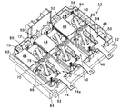
次いで、第1実施例に係るPDU22について説明する。図2はPDU22を示す斜視図であり、図3はその平面図である。
Next, the
PDU22は、1個のヒートシンク40と、複数個(6個)のパワーモジュール26と、複数個のパワーモジュール26に接続されて平滑回路を構成する複数個(3個)のコンデンサ(平滑コンデンサ)44と、パワーモジュール26やコンデンサ44、後述する押圧部材などを収容すると共に、ヒートシンク40上に取り付けられるケース46とを備える。尚、PDU22は、MOTECU28などを構成し、パワーモジュール26に信号ピン48を介して接続される電子回路基板、およびヒートシンク40に取り付けられてケース46などを被覆するカバーなども備えるが、それらは本願の要旨と直接の関係を有しないので、図示および説明を省略する。
The PDU 22 includes one
以下、PDU22を構成する各要素について説明すると、6個のパワーモジュール26は、3相のインバータ回路を形成するためのIGBT(図示せず)をそれぞれ備え、3相インバータ回路モジュールとして構成される。より詳しくは、ハイサイドスイッチ(スイッチング素子)を有するパワーモジュールと、ローサイドスイッチ(スイッチング素子)を有するパワーモジュールが直列接続されて単相のインバータ回路を形成し、単相のインバータ回路が3組並列接続されることで、6個のパワーモジュール26は3相インバータ回路モジュールとして構成される。
Hereinafter, each element constituting the
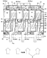
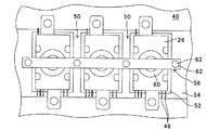
6個のパワーモジュール26は、図3に良く示す如く、ヒートシンク40(正確にはヒートシンク40に取り付けられたケース46の内部空間)に千鳥状に配置される。これにより、パワーモジュール26は互いに離間して配置され、パワーモジュール26の間に6個の空間50が形成される。尚、図3において、紙面下段に並列に配置される3個のパワーモジュール26はハイサイドスイッチ側であり、紙面上段に並列に配置される3個のパワーモジュール26はローサイドスイッチ側である。
The six
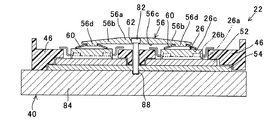
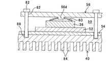
図4は、図3に示すパワーモジュール26を紙面右側から見た状態を模式的に示す模式断面図である。
FIG. 4 is a schematic cross-sectional view schematically showing a state where the
図4に示す如く、パワーモジュール26は、ベースプレート26aと、ベースプレート26aの上方に配置され、動作時に発熱する電子部品(具体的にはIGBT。以下「発熱部品」という)26bを備え、ベースプレート26aや発熱部品26bなどが封止樹脂26cによってモールド成型されてなる。尚、この明細書において、上方や下方などの上下関係を示す記載は、図2に示すPDU22においてパワーモジュール26側を上、ヒートシンク40側を下とするときの上下関係を表すものとする。
As shown in FIG. 4, the
パワーモジュール26とヒートシンク40の間には、熱伝導性を有する材質(例えば銅など)からなる熱拡散板52と、熱拡散板52の下方に配置される熱伝導性絶縁シート54が介挿される。
Between the
また、2個のパワーモジュール26の上方には押圧部材56が配置されると共に、複数個のパワーモジュール26と押圧部材56の間には、略円形状のバネ部材60がそれぞれ配置される。より詳しくは、単相のインバータ回路を構成するハイサイドスイッチ側のパワーモジュール26とローサイドスイッチ側のパワーモジュール26の上方に、1個の押圧部材56が配置される。PDU22においては、前記したように、単相のインバータ回路が3組並列接続されるため、押圧部材56も3個配置されることになる。
Further, a pressing
押圧部材56は、図3などに良く示すように、平面視略I字状を呈すると共に、鉄(例えばSS400)から製作される。押圧部材56は、中央部にネジ挿通孔62が1個穿設されるネジ挿通部56aと、ネジ挿通部56aから連続して形成される2本のアーム部56bからなる。2本のアーム部56bは、ネジ挿通孔62を中心として相互に180度の間隔をおいて形成される。
As shown in FIG. 3 and the like, the pressing
押圧部材56の下面、正確には押圧部材のアーム部56bの下面(具体的にはパワーモジュール26に対向する面)56cには、凸部56dが突設される。一方の凸部56dからネジ挿通孔62までの距離は、他方の凸部56dからネジ挿通孔62までのそれと略同一の値とされる。
A
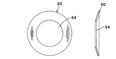
図5は、図3,4などに示すバネ部材60を拡大して表す拡大平面図と拡大断面図である。
FIG. 5 is an enlarged plan view and an enlarged sectional view showing the
バネ部材60は、前記したように略円形状を呈すると共に、ステンレス材(例えばSUS301−CSP−H)から製作される。バネ部材60の中央部には、押圧部材の凸部56dと嵌合する嵌合孔64が穿設される。このようにバネ部材60は、いわゆる皿バネ(弾性部材)からなる。
The
尚、図4から分かるように、前記した発熱部品26bはパワーモジュール26におけるバネ部材60とヒートシンク40との間の部位、別言すれば押圧部材56からバネ部材60を介して下方に押圧される力が作用する部位に配置される。
As can be seen from FIG. 4, the
図2および図3の説明を続けると、3個のコンデンサ44は、6個のパワーモジュールの間に形成される空間50に配置される。より正確には、3個のコンデンサ44は全てローサイドスイッチ側のパワーモジュール26の間に形成される空間50(図3で符号50aで示す)に配置される一方、ハイサイドスイッチ側のパワーモジュール26の間に形成される空間50(図3で符号50bで示す)にはコンデンサが配置されない。
2 and FIG. 3, the three
コンデンサ44は、P端子(正の電極端子)70とN端子(負の電極端子)72を備える。P端子70は、バッテリ24の高位端(図示せず)とパワーモジュール26のハイサイドスイッチ側の入力端子(図で見えず)に接続される。一方、N端子72は、バッテリ24の低位端(図示せず)とパワーモジュール26のローサイドスイッチ側の入力端子(図で見えず)に接続される。尚、パワーモジュール26において、ハイサイドスイッチ側の出力端子とローサイドスイッチ側の出力端子(共に図2,3で見えず)はバスバー74を介して接続されると共に、バスバー74の出力端子74aはPDU22の外方に向けて突出させられる。
The
ケース46は、絶縁材(例えば樹脂材など)から製作されると共に、パワーモジュール26、コンデンサ44、熱拡散板52および熱伝導性絶縁シート54などを取り囲むような形状とされる。ケース46において押圧部材のネジ挿通部56aに対応する位置には、回転防止壁76が3個設けられる。
The
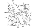
図6は、図2に示す回転防止壁76部分を拡大して示す拡大斜視図である。
FIG. 6 is an enlarged perspective view showing the
回転防止壁76は、平面視略四角形状を呈すると共に、押圧部材のネジ挿通部56a(正確には、ネジ挿通部のネジ挿通孔62)を取り囲むように形成される。回転防止壁76においてネジ挿通部56aから延びるアーム部56bが位置させられるべき部位には切り欠き部80が設けられる。
The
上記の如く構成することで、例えば押圧部材のネジ挿通孔62にネジ82が挿通されて締め付けられる際(即ち、時計回りに回転させられる際)、押圧部材のアーム部56bは回転防止壁76の切り欠き部80に当接させられるため、押圧部材56自体が回転させられることはない。逆にネジ82が緩められる方向(反時計回り方向)に回転させられるときであっても同様に、アーム部56bは切り欠き部80に当接させられるため、押圧部材56自体が回転させられることはない。このように、ヒートシンク40に取り付けられるケース46には、押圧部材56の回転を防止する回転防止壁76が設けられる。
By configuring as described above, for example, when the
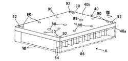
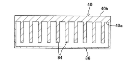
図7は図2などに示すヒートシンク40の斜視図であり、図8は図7のVIII−VIII線模式断面図である。
7 is a perspective view of the
ヒートシンク40は、例えばアルミニウムなどの熱伝導性を有する材質からなると共に、その下面40aには冷却フィン84が複数本形成される。冷却フィン84は、図示の如く、ヒートシンク40の長手方向と直交する方向、別言すれば、後述する冷却風の向きと平行な方向になるように突設される。
The
冷却フィン84には、冷却風を流通させるダクト(図7において想像線で示す)86が取り付けられる。これにより、例えばパワーモジュール26などで生じた熱は、熱拡散板52や熱伝導性絶縁シート54などを介してヒートシンク40の冷却フィン84に伝達された後、ダクト86を流れる冷却風によって放熱(冷却)させられる。
A duct 86 (shown by an imaginary line in FIG. 7) for circulating cooling air is attached to the cooling
ヒートシンク40の上面(ケース46が取り付けられる面)40bの前記ネジ挿通孔62に対応する位置にはネジ穴88が3個穿設される。また、ヒートシンク40の上面40bの適宜位置には、ケース46を取り付けるためのケース用取り付け穴90が複数個(12個)穿設されると共に、四隅には図示しないカバーを取り付けるためのカバー用取り付け穴92が穿設される。
Three screw holes 88 are formed at positions corresponding to the screw insertion holes 62 on the upper surface (surface to which the
次いで、上記の如く構成されたPDU22の組付け(組立て)について、図2から4を参照しつつ説明する。
Next, assembly (assembly) of the
先ず熱伝導性絶縁シート54がヒートシンク40上に配置され、その上に熱拡散板52が敷設される。次いで、ケース46がヒートシンク40上に載置され、12本のネジ94(図2,3において1本見えず)がケース46を介してケース用取り付け穴90に挿通させられることで、ケース46はヒートシンク40に固定される。そして、6個のパワーモジュール26が熱拡散板52と熱伝導性絶縁シート54を介してヒートシンク40に配置、詳しくは千鳥状に配置される。
First, the heat conductive insulating
バネ部材60がパワーモジュール26の中央部付近に載置された後、押圧部材56はバネ部材60の上方に位置させられる。このとき、押圧部材のネジ挿通部56aは回転防止壁76で画成される内部空間に位置させられて位置決めされる。即ち、回転防止壁76は、押圧部材56のケース46に対する位置決めとしての機能も有する。
After the
次いで、押圧部材56は、凸部56dがバネ部材の嵌合孔64に嵌合させられつつ下方へ移動させられる。前述したように、凸部56dから押圧部材のネジ挿通孔62までの距離は、他方の凸部56dからネジ挿通孔62までのそれと略同一の値とされるため、結果として2個(複数個)のパワーモジュール26は、ネジ挿通孔62から同一の距離に配置されることとなる。
Next, the pressing
そしてネジ82はネジ挿通孔62およびヒートシンク40のネジ穴88に挿通させられる、即ち、ネジ82を締め付けることで押圧部材56のアーム部56bはバネ部材60を介してパワーモジュール26を下方へ押圧する。これにより、6個のパワーモジュール26はヒートシンク40上に押圧部材56で押圧されつつ固定される。尚、このときのバネ部材60に作用する力は、例えば1.5〜2.0kN程度とされる。
The
コンデンサ44は空間50aに配置されてパワーモジュール26やバッテリ24などに接続されると共に、パワーモジュール26の信号ピン48も図示しない電子回路基板と電気的に接続される。次いで、カバー用取り付け穴92とカバーの取り付け穴(図示せず)に図示しないネジを挿通させることによってヒートシンク40にカバーが取り付けられ、PDU22が完成する。
The
その後、ダクト86が、図7に示す如くヒートシンク40の冷却フィン84に取り付けられ、そこを流れる冷却風によってパワーモジュール26は冷却される。具体的に説明すると、ダクト86の冷却風は、図3,7に矢印Aで示す如く、冷却フィン84と平行な方向に流通させられる。ヒートシンク40は、前述したように、パワーモジュール26が押圧部材56からバネ部材60を介して押圧されるため、ヒートシンク40とパワーモジュール26は熱的に結合されている。そのため、パワーモジュール26の熱は熱拡散板52と熱伝導性絶縁シート54を介してヒートシンク40(正確には、ヒートシンク40の冷却フィン84)に伝達され、冷却フィン84はダクト86の冷却風によって冷却される。このようにしてパワーモジュール26は冷却される。
Thereafter, the
このとき、6個のパワーモジュール26は千鳥状に配置されるため、風上に位置するパワーモジュール26(ハイサイドスイッチ側)の熱によって昇温させられた冷却風が、風下に位置するパワーモジュール26(ローサイドスイッチ側)の下方にある冷却フィン84に当たらないようにすることができる。即ち、ヒートシンク40において複数個のパワーモジュール26が固定される部位近傍の冷却フィン(放熱部)84の全てに比較的低温の冷却風を直接当てることができ、パワーモジュール26を効率良く冷却することができる。
At this time, since the six
このように、第1実施例に係るPDU22にあっては、ヒートシンク40上に押圧部材56で押圧されつつ固定されるパワーモジュール26を備えると共に、パワーモジュール26と押圧部材56の間に略円形状のバネ部材60を配置するように構成、即ち、パワーモジュールにネジ挿通孔などを穿設することなく、押圧部材56でパワーモジュール26を略円形状のバネ部材60を介して押圧してヒートシンク40上に固定するように構成したので、レイアウトの制限あるいは放熱性の低下などを招くことなく、ヒートシンク40上にパワーモジュール26を固定することができる。また、パワーモジュール26の内部であってバネ部材60とヒートシンク40との間の部位、別言すれば押圧部材56からバネ部材60を介して押圧される力が作用する部位に、発熱部品26bを配置するように構成したので、前記発熱部品26bはヒートシンク40との密着性が向上、即ち、発熱部品26bとヒートシンク40との熱結合が良くなり、発熱部品26bの熱をヒートシンク40に効率良く伝達させることが可能となる(放熱性を向上させることができる)。また、バネ部材60が円形状を呈するように構成したので、パワーモジュール26とヒートシンク40との間に熱拡散板52を介挿する場合、パワーモジュール26と熱拡散板52の組み合わせによって生じる高さ(厚さ)のバラツキをバネ部材60により吸収でき、よってパワーモジュール26に作用する荷重を均一にすることができる。
As described above, the
また、押圧部材56に凸部56dを突設すると共に、バネ部材60の中央部に、凸部と嵌合する嵌合孔64を穿設するように構成したので、押圧部材の凸部56dをバネ部材の嵌合孔64に嵌合させることで押圧部材56がバネ部材60に対して位置ズレすることがなく、よってパワーモジュール26に作用する荷重をより一層均一にすることができる。
In addition, since the
また、パワーモジュール26が複数個からなると共に、押圧部材56で複数個のパワーモジュール26を押圧しつつ固定するように構成、即ち、押圧部材56で一度に複数個のパワーモジュール26を押圧しつつ固定するように構成したので、組立工数を削減することができる。
In addition, the
次いで、この発明の第2実施例に係るパワードライブユニットについて説明する。 Next, a power drive unit according to the second embodiment of the present invention will be described.
図9は第2実施例に係るパワードライブユニットのパワーモジュール26部分を拡大して模式的に示す拡大模式平面図であり、図10は図9に示すパワーモジュール26の一部を拡大して表す拡大部分断面図である。尚、図9,10において、ケース46などの図示を省略した。
FIG. 9 is an enlarged schematic plan view schematically showing an enlarged portion of the
以下、第1実施例と相違する点に焦点をおいて説明すると、第2実施例にあっては、図9,10に示す如く、1個のパワーモジュール26がハイサイドスイッチとローサイドスイッチの両方を有し、それを3個並列に接続(配置)することで、3相インバータ回路モジュールを構成すると共に、3個のパワーモジュール26を1個の押圧部材56で押圧してヒートシンク40に固定するようにした。
The following description focuses on differences from the first embodiment. In the second embodiment, as shown in FIGS. 9 and 10, one
詳説すると、押圧部材56の適宜位置に4個のネジ挿通孔62が穿設される。正確には、押圧部材56の両端部近傍と、押圧部材56を3個のパワーモジュール26の上方に位置させたとき、パワーモジュール26の間の空間50に対応する位置にネジ挿通孔62が穿設される。また、ヒートシンク40の前記ネジ挿通孔62に対応する位置には、ネジ穴88が穿設される。
More specifically, four screw insertion holes 62 are formed at appropriate positions of the pressing
従って、ネジ82がネジ挿通孔62とネジ穴88に挿通させられることで、換言すれば、ネジ82を締め付けることで押圧部材56はバネ部材60を介してパワーモジュール26を下方へ押圧する、即ち、3個のパワーモジュール26は1個の押圧部材56によって一度にヒートシンク40に押圧されつつ固定される。
Therefore, when the
このように、この発明の第2実施例に係るPDU22にあっては、3個のパワーモジュール26を1個の押圧部材56で押圧しつつ固定するように構成したので、第1実施例と同様な効果を得ることができる。
As described above, in the
尚、残余の構成は第1実施例のそれと異ならない。 The remaining configuration is not different from that of the first embodiment.
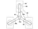
次いで、この発明の第3実施例に係るパワードライブユニットについて説明する。 Next explained is a power drive unit according to the third embodiment of the invention.
図11は、第3実施例に係るパワードライブユニットを構成する押圧部材56の変形例を示す平面図である。
FIG. 11 is a plan view showing a modification of the pressing
以下、第1実施例と相違する点に焦点をおいて説明すると、第3実施例にあっては、図11に示す如く、押圧部材のネジ挿通部56aにはアーム部56bが3本形成される。3本のアーム部56bは、ネジ挿通部56aのネジ挿通孔62を中心として相互に120度の間隔をおいて形成される。従って、パワーモジュール26(正確には、パワーモジュール26の中心部)は、破線で示すように、ネジ挿通孔62から同一の距離であって、かつネジ挿通孔62を中心として相互に120度の間隔をおいて配置される。
The following description focuses on the differences from the first embodiment. In the third embodiment, as shown in FIG. 11, the
このように、この発明の第3実施例に係るPDU22にあっては、押圧部材のアーム部56bが3本形成されるように構成したので、1個の押圧部材56で一度に3個のパワーモジュール26をヒートシンク40上に押圧しつつ固定することが可能となる。
As described above, the
尚、残余の構成および効果は、従前の実施例のそれと異ならない。 The remaining configuration and effects are not different from those of the previous embodiments.
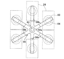
次いで、この発明の第4実施例に係るパワードライブユニットについて説明する。 Next explained is a power drive unit according to the fourth embodiment of the invention.
図12は、第4実施例に係るパワードライブユニットを構成する押圧部材56の変形例を示す、図11と同様な平面図である。
FIG. 12 is a plan view similar to FIG. 11 showing a modification of the pressing
以下、第1実施例と相違する点に焦点をおいて説明すると、第4実施例にあっては、図12に示す如く、押圧部材のネジ挿通部56aにはアーム部56bが6本形成される。6本のアーム部56bは、ネジ挿通部56aのネジ挿通孔62を中心として相互に60度の間隔をおいて形成される。従って、パワーモジュール26(正確には、パワーモジュール26の中心部)は、破線で示すように、ネジ挿通孔62から同一の距離であって、かつネジ挿通孔62を中心として相互に60度の間隔をおいて配置される。
The following description focuses on the differences from the first embodiment. In the fourth embodiment, as shown in FIG. 12, the
このように、この発明の第4実施例に係るパワードライブユニットにあっては、押圧部材のアーム部56bが6本形成されるように構成したので、1個の押圧部材56で一度に6個のパワーモジュール26をヒートシンク40上に押圧しつつ固定することができる。
As described above, in the power drive unit according to the fourth embodiment of the present invention, since the six
尚、残余の構成および効果は、第1から3の実施例のそれと異ならない。 The remaining configuration and effects are not different from those of the first to third embodiments.
以上の如く、この発明の第1から4実施例にあっては、ヒートシンク40と、前記ヒートシンク上に押圧部材56で押圧されつつ固定されるパワーモジュール26とを少なくとも備えるパワードライブユニット(PDU)22において、前記パワーモジュールと前記押圧部材の間に略円形状、より具体的には図3に示すような略円形状のバネ部材60を配置するように構成した。
As described above, in the first to fourth embodiments of the present invention, in the power drive unit (PDU) 22 including at least the
また、前記押圧部材に凸部56dを突設すると共に、前記バネ部材の中央部に、前記凸部と嵌合する嵌合孔64を穿設するように構成した。
Further, a
また、前記パワーモジュール26が複数個からなると共に、前記押圧部材56で前記複数個のパワーモジュール26を押圧しつつ固定するように構成した。
In addition, the
尚、上記において、パワードライブユニット22をハイブリッド車両に搭載される例で説明をしたが、この発明に係るパワードライブユニット22は、電気自動車にも適用可能である。
In the above, the example in which the
22 パワードライブユニット(PDU)、26 パワーモジュール、40 ヒートシンク、56 押圧部材、56d 凸部、60 バネ部材、64 嵌合孔 22 power drive unit (PDU), 26 power module, 40 heat sink, 56 pressing member, 56d convex part, 60 spring member, 64 fitting hole
Claims (2)
Priority Applications (2)
| Application Number | Priority Date | Filing Date | Title |
|---|---|---|---|
| JP2007333581A JP5154912B2 (en) | 2007-12-26 | 2007-12-26 | Power drive unit |
| US12/292,630 US8120171B2 (en) | 2007-12-26 | 2008-11-21 | Power drive unit including a heat sink and a fastener |
Applications Claiming Priority (1)
| Application Number | Priority Date | Filing Date | Title |
|---|---|---|---|
| JP2007333581A JP5154912B2 (en) | 2007-12-26 | 2007-12-26 | Power drive unit |
Publications (2)
| Publication Number | Publication Date |
|---|---|
| JP2009158631A JP2009158631A (en) | 2009-07-16 |
| JP5154912B2 true JP5154912B2 (en) | 2013-02-27 |
Family
ID=40962347
Family Applications (1)
| Application Number | Title | Priority Date | Filing Date |
|---|---|---|---|
| JP2007333581A Expired - Fee Related JP5154912B2 (en) | 2007-12-26 | 2007-12-26 | Power drive unit |
Country Status (1)
| Country | Link |
|---|---|
| JP (1) | JP5154912B2 (en) |
Families Citing this family (5)
| Publication number | Priority date | Publication date | Assignee | Title |
|---|---|---|---|---|
| JP5500718B2 (en) | 2010-03-05 | 2014-05-21 | 株式会社ケーヒン | Semiconductor device |
| JP5397417B2 (en) * | 2011-05-30 | 2014-01-22 | 株式会社デンソー | Semiconductor device and driving device using the same |
| JP5971190B2 (en) * | 2012-06-07 | 2016-08-17 | 株式会社豊田自動織機 | Semiconductor device |
| JP2015050257A (en) * | 2013-08-30 | 2015-03-16 | 株式会社東芝 | Power conversion device for vehicle and railway vehicle |
| JPWO2025083852A1 (en) * | 2023-10-19 | 2025-04-24 |
Family Cites Families (2)
| Publication number | Priority date | Publication date | Assignee | Title |
|---|---|---|---|---|
| JPS6422051U (en) * | 1987-07-30 | 1989-02-03 | ||
| JP3725103B2 (en) * | 2002-08-23 | 2005-12-07 | 三菱電機株式会社 | Semiconductor device |
-
2007
- 2007-12-26 JP JP2007333581A patent/JP5154912B2/en not_active Expired - Fee Related
Also Published As
| Publication number | Publication date |
|---|---|
| JP2009158631A (en) | 2009-07-16 |
Similar Documents
| Publication | Publication Date | Title |
|---|---|---|
| US8120171B2 (en) | Power drive unit including a heat sink and a fastener | |
| JP5328147B2 (en) | Power drive unit | |
| JP5154913B2 (en) | Power drive unit | |
| KR101022000B1 (en) | Semiconductor module and driving device of hybrid vehicle having same | |
| EP1788596B1 (en) | Capacitor module, power converter and vehicle-mounted electrical-mechanical system | |
| JP4964103B2 (en) | Power drive unit | |
| KR100749173B1 (en) | Cooling structure of electric device | |
| JP4909712B2 (en) | Power converter | |
| US8054633B2 (en) | Power converter | |
| JP5500718B2 (en) | Semiconductor device | |
| JP4979909B2 (en) | Power converter | |
| JP5511515B2 (en) | Power converter | |
| JP5154912B2 (en) | Power drive unit | |
| JP4313273B2 (en) | Power drive unit | |
| JP2006332291A (en) | Power drive unit | |
| JP2009177000A (en) | Capacitor device | |
| JP5791670B2 (en) | Power converter | |
| JP2019103247A (en) | Cooling structure for power converter | |
| KR20190076514A (en) | Power semiconductor mounting structure | |
| JP5730224B2 (en) | Inverter unit, integrated electric compressor | |
| JP5699790B2 (en) | Terminal block assembly structure | |
| US20240322673A1 (en) | Base plate and single-phase module of an inverter, inverter and power electronics | |
| JP2013016634A (en) | Cooling structure of semiconductor element | |
| JP2001020737A (en) | Forced cooling device | |
| JP2010239810A (en) | Inverter device and manufacturing method thereof |
Legal Events
| Date | Code | Title | Description |
|---|---|---|---|
| A621 | Written request for application examination |
Free format text: JAPANESE INTERMEDIATE CODE: A621 Effective date: 20100921 |
|
| A977 | Report on retrieval |
Free format text: JAPANESE INTERMEDIATE CODE: A971007 Effective date: 20110222 |
|
| A131 | Notification of reasons for refusal |
Free format text: JAPANESE INTERMEDIATE CODE: A131 Effective date: 20120822 |
|
| A521 | Request for written amendment filed |
Free format text: JAPANESE INTERMEDIATE CODE: A523 Effective date: 20121018 |
|
| TRDD | Decision of grant or rejection written | ||
| A01 | Written decision to grant a patent or to grant a registration (utility model) |
Free format text: JAPANESE INTERMEDIATE CODE: A01 Effective date: 20121121 |
|
| A61 | First payment of annual fees (during grant procedure) |
Free format text: JAPANESE INTERMEDIATE CODE: A61 Effective date: 20121206 |
|
| FPAY | Renewal fee payment (event date is renewal date of database) |
Free format text: PAYMENT UNTIL: 20151214 Year of fee payment: 3 |
|
| R150 | Certificate of patent or registration of utility model |
Ref document number: 5154912 Country of ref document: JP Free format text: JAPANESE INTERMEDIATE CODE: R150 Free format text: JAPANESE INTERMEDIATE CODE: R150 |
|
| R250 | Receipt of annual fees |
Free format text: JAPANESE INTERMEDIATE CODE: R250 |
|
| R250 | Receipt of annual fees |
Free format text: JAPANESE INTERMEDIATE CODE: R250 |
|
| R250 | Receipt of annual fees |
Free format text: JAPANESE INTERMEDIATE CODE: R250 |
|
| LAPS | Cancellation because of no payment of annual fees |