JP5154910B2 - Headrest - Google Patents
Headrest Download PDFInfo
- Publication number
- JP5154910B2 JP5154910B2 JP2007332311A JP2007332311A JP5154910B2 JP 5154910 B2 JP5154910 B2 JP 5154910B2 JP 2007332311 A JP2007332311 A JP 2007332311A JP 2007332311 A JP2007332311 A JP 2007332311A JP 5154910 B2 JP5154910 B2 JP 5154910B2
- Authority
- JP
- Japan
- Prior art keywords
- shaft
- bearing
- auxiliary
- axial direction
- auxiliary frame
- Prior art date
- Legal status (The legal status is an assumption and is not a legal conclusion. Google has not performed a legal analysis and makes no representation as to the accuracy of the status listed.)
- Expired - Fee Related
Links
- 230000000903 blocking effect Effects 0.000 claims description 15
- 230000002093 peripheral effect Effects 0.000 claims description 5
- 230000000452 restraining effect Effects 0.000 claims description 4
- 238000000465 moulding Methods 0.000 description 14
- 238000004519 manufacturing process Methods 0.000 description 8
- 229920003002 synthetic resin Polymers 0.000 description 5
- 239000000057 synthetic resin Substances 0.000 description 5
- 230000000694 effects Effects 0.000 description 4
- 239000002184 metal Substances 0.000 description 4
- 230000001105 regulatory effect Effects 0.000 description 3
- 238000007493 shaping process Methods 0.000 description 3
- 230000015572 biosynthetic process Effects 0.000 description 2
- 210000002615 epidermis Anatomy 0.000 description 1
- 239000000463 material Substances 0.000 description 1
- 238000000034 method Methods 0.000 description 1
- 230000002265 prevention Effects 0.000 description 1
- 210000003491 skin Anatomy 0.000 description 1
Images


Landscapes
- Chair Legs, Seat Parts, And Backrests (AREA)
- Seats For Vehicles (AREA)
Description
この発明は、自動車等の車両の座席に装着されるヘッドレストに関し、特に中央部の主レスト部の両側に補助レスト部を前後方向へ回動可能に支持したヘッドレストに関するものである。 The present invention relates to a headrest that is mounted on a seat of a vehicle such as an automobile, and more particularly to a headrest that supports auxiliary rest portions on both sides of a central main rest portion so as to be rotatable in the front-rear direction.
従来、この種のヘッドレストとしては、例えば特許文献1に開示されるような構成が提案されている。この従来構成においては、主レスト部の主フレームと補助レスト部の補助フレームとが別体で構成されている。そして、主フレームが補助フレームの両側に対して、複数のボルト及びナットにより前後方向へ回動可能に枢着されている。 Conventionally, as this type of headrest, for example, a configuration as disclosed in Patent Document 1 has been proposed. In this conventional configuration, the main frame of the main rest portion and the auxiliary frame of the auxiliary rest portion are configured separately. The main frame is pivotally attached to both sides of the auxiliary frame so as to be rotatable in the front-rear direction by a plurality of bolts and nuts.
この従来構成においては、主フレームと補助フレームとを別々に製造する必要があって、これらのフレームを合成樹脂製とした場合、成形型も別々に用意する必要がある。また、主フレーム及び補助フレームを複数のボルト及びナットにより回動可能に組み付ける必要がある。このため、部品点数が多くなって、製造及び組み付けが煩雑になるという問題があった。 In this conventional configuration, it is necessary to manufacture the main frame and the auxiliary frame separately, and when these frames are made of synthetic resin, it is necessary to prepare a mold separately. Further, it is necessary to assemble the main frame and the auxiliary frame so as to be rotatable by a plurality of bolts and nuts. For this reason, there has been a problem that the number of parts increases, and manufacturing and assembly become complicated.
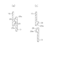
このような問題に対処するため、例えば図12及び図13に示すような構成のヘッドレストも従来から提案されている。この従来構成においては、主レスト部31の主フレーム32と補助レスト部33の補助フレーム34とが、軸35及び軸受36をインサートした状態で合成樹脂により一体に成形されている。主フレーム32と補助フレーム34とは所定の間隔S4をおいて配置され、補助フレーム34は主フレーム32に対して軸35及び軸受36を介して前後方向へ回動可能に連結されている。軸35の両端近傍において、補助フレーム34の主フレーム32側の端縁には規制部37が一体形成されている。そして、補助フレーム34が前方に回動されたとき、この規制部37が主フレーム32の端縁に当接することにより、補助フレーム34の回動範囲が規制される。
前述した図12及び図13に示す従来構成においては、軸35及び軸受36がインサートされるとともに、それらが組付けられた状態となるように、主フレーム32及び補助フレーム34は1つの成形用金型を使用して同時に成形される。そして、主フレーム32及び補助フレーム34を成形する際に、両フレーム32,34間に成形用金型の一部(突部)が介在される。従って、その成形用金型の介在部分が薄いと、その部分の強度が不足するため、その介在部分を所定以上の肉厚に形成して、強度を確保する必要がある。このため、主フレーム32と補助フレーム34との間の間隔S4が広くなって、そのままでは、規制部37を主フレーム32の外側面に対して当接可能に配置させることが困難になり、補助フレーム34の回動範囲を適正に規制することができない。
In the conventional configuration shown in FIG. 12 and FIG. 13 described above, the
従って、図12及び図13に示す従来構成では、規制部37が複数の薄板リブ状に分割成形されている。このように構成した場合には、成形用金型の介在部分の薄肉部が規制部37の先端と対応する部分のみとなる。このため、成形型の介在部分の強度をある程度確保できる。そして、規制部37を主フレーム32の端縁に対して、主フレーム32と補助フレーム34との間の間隔S4よりも狭い間隔S5で配置することができて、図13から明らかなように、補助フレーム34の回動範囲を適正に規制することができる。
Therefore, in the conventional configuration shown in FIGS. 12 and 13, the restricting
しかしながら、この規制部37の分割構成では、薄板リブ状の規制部37が主フレーム32の外側面に対して点当たりに近い状態で接触し、接触面積が小さい。このため、規制部37の先端部が圧潰されて損傷しやすく、圧潰されてしまうと、補助フレーム34を所定の回動範囲に規制することが困難になるという問題があった。
However, in this divided configuration of the restricting
この発明は、このような従来の技術に存在する問題点に着目してなされたものである。その目的は、製作が容易であるとともに、補助フレームの回動範囲を適正に規制することができるとともに、主フレームと補助フレームとの間において成形型の強度を維持できるヘッドレストを提供することにある。 The present invention has been made paying attention to such problems existing in the prior art. An object of the present invention is to provide a headrest that is easy to manufacture, can appropriately regulate the rotation range of the auxiliary frame, and can maintain the strength of the mold between the main frame and the auxiliary frame. .
上記の目的を達成するために、この発明においては、主レスト部の主フレームの両側に、補助レスト部の補助フレームを軸及び軸受を介して前後方向へ回動可能に支持したヘッドレストにおいて、前記軸を軸受に対して軸線方向へ相対移動可能に、かつ軸線を中心に相対回動可能に挿通し、前記軸と軸受との間には、軸が軸受に対して軸線方向の一方の位置に配置された状態において、それらの間の相対回動を阻止する阻止手段を設けている。そして、前記両フレームには、前記軸が軸線方向の前記一方の位置に配置されたときに、互いに離間するとともに、軸が軸線方向の他方の位置に配置されたときに、当接可能に対向して補助フレームの回動範囲を規制する規制部をそれぞれ形成している。 In order to achieve the above object, according to the present invention, in the headrest that supports the auxiliary frame of the auxiliary rest portion on both sides of the main frame of the main rest portion so as to be rotatable in the front-rear direction via a shaft and a bearing, The shaft is inserted so as to be able to move relative to the bearing in the axial direction and so as to be rotatable relative to the axis, and between the shaft and the bearing, the shaft is positioned at one position in the axial direction with respect to the bearing. Blocking means for blocking relative rotation between them in the disposed state is provided. The two frames are separated from each other when the shaft is arranged at the one position in the axial direction, and are opposed to each other when the shaft is arranged at the other position in the axial direction. Thus, restricting portions for restricting the rotation range of the auxiliary frame are formed.
従って、この発明のヘッドレストの製作時には、主レスト部の主フレームと補助レスト部の補助フレームとが、軸及び軸受をインサートした状態で一体に成形される。この場合、軸が軸受に対して軸線方向の一方の位置に配置されて、阻止手段により軸と軸受との間の相対回動が阻止される。そして、この回動阻止状態において、主フレームと補助フレームと対向端部に、規制部が互いに離間した状態で形成される。よって、主フレームと補助フレームとを別々に成形して回動可能に組み付ける必要がなく、製作を容易に行うことができるとともに、主フレームと補助フレームとの間に広い間隔を確保でき、成形用金型についても十分な強度を確保することができる。 Accordingly, when the headrest of the present invention is manufactured, the main frame of the main rest portion and the auxiliary frame of the auxiliary rest portion are integrally formed with the shaft and the bearing inserted. In this case, the shaft is disposed at one position in the axial direction with respect to the bearing, and relative rotation between the shaft and the bearing is prevented by the blocking means. And in this rotation prevention state, it forms in the state which the control part was mutually separated in the main frame, the auxiliary | assistant frame, and the opposing edge part. Therefore, it is not necessary to mold the main frame and the auxiliary frame separately and assemble them so that they can be rotated, making it easy to manufacture and ensuring a wide space between the main frame and the auxiliary frame. Sufficient strength can be secured for the mold.
さらに、このヘッドレストの成形後に、軸が軸受に対して軸線方向の一方の位置から他方の位置に移動配置されて、軸と軸受との間の相対回動が許容される。そして、この回動許容状態において、主フレーム及び補助フレームの規制部が当接可能に離間して対向配置される。よって、ヘッドレストの使用時には、規制部が互いに当接することにより、補助フレームを所定の回動範囲にて適正に規制することができる。 Further, after the headrest is formed, the shaft is moved from one position in the axial direction to the other position with respect to the bearing to allow relative rotation between the shaft and the bearing. And in this rotation permission state, the restricting portions of the main frame and the auxiliary frame are arranged to face each other so as to be able to come into contact with each other. Therefore, when the headrest is used, the auxiliary frames can be properly restricted within a predetermined rotation range by the restriction portions coming into contact with each other.
前記の構成において、前記阻止手段は、前記軸の外周に突設されたキーと、そのキーと係合可能に対応するように、軸受の内周面に形成され、軸の軸線方向に延びる係合溝と、その係合溝と連通するように、軸受の内周面に形成され、前記キーの回動を許容する環状凹部とから構成されるとよい。この構成において、前記補助フレームが後方への展開状態のときに前記キーが係合溝に係合されるように構成するとよい。 In the above configuration, the blocking means is formed on the inner peripheral surface of the bearing so as to be capable of engaging with the key protruding from the outer periphery of the shaft, and extends in the axial direction of the shaft. It is good to be comprised from the annular recessed part which is formed in the internal peripheral surface of a bearing and accept | permits rotation of the said key so that it may connect with the engaging groove. In this configuration, it is preferable that the key is engaged with the engagement groove when the auxiliary frame is in the rearward deployed state.
また、前記規制部を主フレーム及び補助フレームにそれぞれ形成するよい。このようにすれば、規制部が主フレーム及び補助フレームの成形と同時に形成される。
さらに、規制部が規制可能に対向した状態において、補助フレームの前記軸の軸線方向への相対移動を制止するための制止手段を設けるとよい。
Further, the restricting portions may be formed on the main frame and the auxiliary frame, respectively. In this way, the restricting portion is formed simultaneously with the formation of the main frame and the auxiliary frame.
Furthermore, it is preferable to provide a stopping means for stopping the relative movement of the auxiliary frame in the axial direction in a state where the restricting portions face each other in a restrictable manner.
以上のように、この発明によれば、製作が容易であるとともに、使用時には補助フレームの回動範囲を適正に規制することができ、しかも主フレームと補助フレームとの間において成形型の強度を維持できるという効果を発揮する。 As described above, according to the present invention, it is easy to manufacture, and the rotation range of the auxiliary frame can be properly regulated during use, and the strength of the mold is increased between the main frame and the auxiliary frame. The effect that it can be maintained is demonstrated.
(第1実施形態)
以下に、この発明の第1実施形態を、図1〜図8に基づいて説明する。
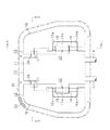
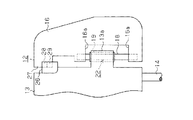
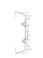
図1〜図3に示すように、この実施形態のヘッドレストは、中央の主レスト部11と、その主レスト部11の両側に前後方向へ回動可能に装着された一対の補助レスト部12とから構成されている。主レスト部11は、合成樹脂製の主フレーム13と、その主フレーム13の下部に突設されたステー14と、主フレーム13の後面に組み付けられた内部機構15とを備えている。内部機構15は金属製ブラケット15aを備え、そのブラケット15a内には、例えば車両の衝突時に主レスト部11の一部を前方に突出させて、着座者の頭部を保護するための機構等が設けられている。
(First embodiment)
Below, 1st Embodiment of this invention is described based on FIGS.
As shown in FIGS. 1 to 3, the headrest of this embodiment includes a central
前記各補助レスト部12は、合成樹脂製の補助フレーム16と、その補助フレーム16の後面に組み付けられたスピーカ等の補助機構17とから構成されている。各補助フレーム16は、主フレーム13の両側に金属製の軸18及び同じく金属製の軸受19を介して前後方向へ回動可能に支持されている。主レスト部11の主フレーム13と内部機構15及び各補助レスト部12の補助フレーム16と補助機構17の外面を被覆するように、それらの外側部にはクッションパッド20と、そのクッションパッド20の表面を覆う表皮21とが装着されている。
Each of the
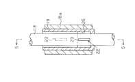
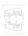
図2及び図3に示すように、前記各軸18は軸受19に対して軸線方向へ相対移動可能に、かつ軸線を中心に相対回動可能に挿通されている。この挿通状態において、各軸18の両端部が各補助フレーム16の突部16aに一体にインサート成形されるとともに、各軸受19が主フレーム13の両側の突部13aに一体にインサート成形されている。各軸18と軸受19との間には、阻止手段としての阻止機構22が設けられている。この阻止機構22は、補助フレーム16が主フレーム13に対して後方へ展開した状態に配置されるとともに、軸18が軸受19に対して軸線方向の一方の位置(図8に示す上方位置)に配置された状態において、軸18と軸受19との間の相対回動を阻止し、軸18が軸受19に対して軸線方向の他方の位置(図2に示す下方位置)に配置された状態において、それらの間の相対回動を許容する。
As shown in FIGS. 2 and 3, the
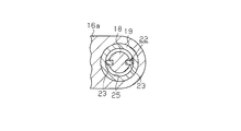
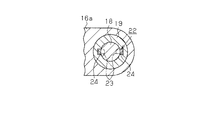
図4〜図7に示すように、前記阻止機構22は、軸18の外周に突設された一対のキー23と、それらのキー23と係合可能に対応するように、軸受19の内周面に形成され、前記軸18の軸線方向に延びる一対の係合溝24と、それらの係合溝24の下端部と連通するように、軸受19の内周面に形成された環状凹部25とから構成されている。なお、前記キー23及び係合溝24は1箇所のみに設けられるものであっても、あるいは3箇所以上に設けられるものであってもよい。そして、補助フレーム16が主フレーム13に対して後方へ展開した状態に配置されるとともに、軸18が軸受19に対して軸線方向の上方位置に配置された状態においては、図4、図5及び図7に鎖線で示すように、各キー23が係合溝24内に配置されて、軸18と軸受19との間の相対回動が阻止される。これに対して、軸18が軸受19に対して軸線方向の下方位置に配置された状態では、図4〜図6に実線で示すように、各キー23が環状凹部25内に配置されて、軸18と軸受19との間の相対回動が許容される。
As shown in FIGS. 4 to 7, the
図2、図3及び図8に示すように、前記主フレーム13の両側部及び各補助フレーム16の内側部には、互いに当接可能な規制部26,27が形成されている。そして、図8に示すように、軸18が軸受19に対して軸線方向の上方位置に配置されたときには、これらの規制部26,27が相互間に所定の間隔S1をおいて離間した状態に配置される。これに対して、図2及び図3に示すように、軸18が軸受19に対して軸線方向の下方位置に配置されたときには、両規制部26,27が当接可能に離間した対向した状態に配置される。そして、この状態においては、規制部26,27の当接により、補助フレーム16が後方への展開状態からさらに後方へ回動されることが規制される。
As shown in FIGS. 2, 3, and 8, restricting
次に、前記のように構成されたヘッドレストの製作方法について説明する。
さて、このヘッドレストを製作する場合には、図8に示すように、軸18を軸受19に挿通して軸線方向の上方位置に配置した状態で、成形用金型100内にセットする。この状態においては、図4、図5及び図7に鎖線で示すように、阻止機構22のキー23が係合溝24内に配置されているため、軸18と軸受19との間の相対回動が阻止されている。そして、この軸18及び軸受19のセット状態で、成形用金型100内に合成樹脂材料を注入することにより、主レスト部11の主フレーム13及び両補助レスト部12の補助フレーム16が軸18及び軸受19のインサート状態にて一体に成形される。そして、この状態は補助フレーム16が主フレーム13に対して後方へ展開した状態である。
Next, a method for manufacturing the headrest configured as described above will be described.
When manufacturing this headrest, as shown in FIG. 8, the
このとき、図8に示すように、主フレーム13の両側部及び各補助フレーム16の内側部には、規制部26,27が相互間に所定の間隔S2をおいて離間した状態に形成される。また、主フレーム13と補助フレーム16との他の対向部間にも、成形用金型100の一部が介在されることによって、所定の間隔S1が形成される。この場合、規制部26,27を相互に接近させて形成する必要がないため、それらの間に介在される成形用金型100の介在部分を肉厚状に形成することができて、金型強度を確保することができる。
At this time, as shown in FIG. 8, the restricting
そして、主フレーム13及び補助フレーム16の成形後に、それらを成形用金型100内から取り出して、図8に矢印で示すように、両補助フレーム16を主フレーム13に対して軸18の軸線方向に沿って下方に相対移動させる。このようにすると、図2に示すように、軸18が軸受19に対して軸線方向の下方位置に移動される。このため、図2及び図3に示すように、主フレーム13側の規制部26と補助フレーム16側の規制部27とが当接可能に対向した状態に配置される。それとともに、図4〜図6に実線で示すように、阻止機構22のキー23が環状凹部25内に配置されて、軸18と軸受19との間の相対回動が許容される。
Then, after the
その後、主フレーム13の後面に内部機構15を組み付けるとともに、各補助フレーム16の後面に補助機構17を組み付ける。この状態で、主レスト部11及び各補助レスト部12の外側部にクッションパッド20を設けるとともに、表皮21を被覆装着すれば、ヘッドレストの製作が終了する。
Thereafter, the
そして、このヘッドレストを車両の座席に装着して使用する際には、軸18と軸受19との間の相対回動が許容されるため、補助レスト部12を主レスト部11に対して前後方向の所望の回動位置に配置することができる。また、この場合には規制部26,27の当接により、補助レスト部12の前方への展開が規制されるため、補助レスト部12が前方へ過回動されるおそれはない。
When the headrest is used while being mounted on a vehicle seat, relative rotation between the
以上のように構成されたこの実施形態においては、以下の効果を発揮する。
(1) この実施形態のヘッドレストにおいては、主レスト部11の主フレーム13と補助レスト部12の補助フレーム16とを別々に成形して回動可能に組み付ける必要がなく、両フレーム13,16を軸18及び軸受19のインサート状態で一体に成形することができる。このため、ヘッドレストの製作を容易に行うことができる。
In this embodiment configured as described above, the following effects are exhibited.
(1) In the headrest of this embodiment, it is not necessary to separately mold the
(2) また、両フレーム13,16の成形時には、規制部26,27を接近状態で対向して成形する必要がなく、所定の間隔S1をおいた状態で成形することができる。よって、それらの規制部26,27間に介在される成形用金型100の介在部分を薄肉状にすることなく肉厚状に形成することができて、金型強度を確保することができる。
(2) Further, when the
(3) さらに、この実施形態のヘッドレストでは、成形後に軸18が軸受19に対して軸線方向の上方位置から下方位置に移動配置されることにより、軸18と軸受19との間の相対回動が許容されるとともに、規制部26,27が当接可能に対向配置される。よって、ヘッドレストの使用時には、規制部26,27が互いに当接することにより、補助レスト部12を所定の回動範囲にて適正に規制することができる。
(3) Further, in the headrest of this embodiment, the relative rotation between the
(4) そして、規制部26,27が相互に当接して位置規制する状態においては、それらの規制部26,27は面当たりで、広い接触面積を確保できる。従って、規制部26,27が損傷することを防止でき、補助フレーム16の回動範囲の規制機能を維持できる。
(4) And in the state which the
(第2実施形態)
次に、この発明の第2実施形態を図9〜図11に基づいて第1実施形態と異なる部分を中心に説明する。
(Second Embodiment)
Next, a second embodiment of the present invention will be described based on FIGS. 9 to 11 with a focus on differences from the first embodiment.
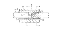
この第2実施形態においては、図9及び図11に示すように、補助フレーム16が主フレーム13に対して後方へ展開されるとともに、規制部26,27が規制可能に対向した状態において、その補助フレーム16の軸18の軸線方向への相対移動を制止するための制止手段を設けたものである。
In the second embodiment, as shown in FIGS. 9 and 11, the
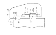
この制止手段は、主レスト部11の主フレーム13の規制部26と補助レスト部12の補助フレーム16の規制部27とにそれぞれ一体形成されたストッパ28,29により構成されている。ただし、補助フレーム16の規制部27は、主フレーム13の規制部26の後方となるように構成する。そして、図11(a)(b)に示すように、それらのストッパ28,29にはそれぞれ案内斜面28a,29aが形成されている。そして、図9及び図10に示すように、軸18と軸受19との間の軸線方向への相対移動が許容される状態において、図11(a)(b)に示すように、それらのストッパ28,29が近接される方向に移動されると、ストッパ28,29どうしが接触し、案内斜面28a,29aの作用により、主フレーム13及び補助フレーム16の弾性に抗してストッパ28,29が相手方に対して後退した後に当接される。この状態では、主フレーム13及び補助フレーム16が軸18と軸受19の軸線方向への相対移動が制止される。
This restraining means is constituted by
従って、この第2実施形態においては、前記第1実施形態の効果に加えて、以下の効果を得ることができる。
(5) 補助フレーム16が主フレーム13に対して後方へ展開されるとともに、規制部26,27が規制可能に対向した状態において、補助フレーム16の前記軸線方向への相対移動を制止するための制止手段が設けられている。従って、軸18と軸受19との関係において、軸18と軸受19との軸線方向への相対移動が許容される状態、すなわち補助フレーム16の後方への展開状態において、その軸線方向への相対移動が制止される。このため、軸18と軸受19との軸線方向への相対移動が許容される状態であっても、補助レスト部12の前記軸線方向へのガタ付きを防止できる。
Therefore, in the second embodiment, in addition to the effects of the first embodiment, the following effects can be obtained.
(5) For restraining relative movement of the
(変更例)
なお、この実施形態は、次のように変更して具体化することも可能である。
・ 前記実施形態では、補助フレーム16の後方への展開状態において、軸18と軸受19との軸線方向への相対移動が許容されるように構成されているが、補助フレーム16のその他の位置、例えば前方へ回動された位置、あるいは後方への展開位置と前方回動位置との中間位置において軸18と軸受19との軸線方向への相対移動が許容されるように構成すること。
(Example of change)
In addition, this embodiment can also be changed and embodied as follows.
In the above-described embodiment, the
・ 前記実施形態において、規制部26,27の形状や形成箇所を変更すること。例えば、規制部26,27を主フレーム13及び補助フレーム16の下部に設けること。
-In the said embodiment, changing the shape and formation location of the
11…主レスト部、12…補助レスト部、13…主フレーム、16…補助フレーム、18…軸、19…軸受、22…阻止手段としての阻止機構、23…キー、24…係合溝、25…環状凹部、26,27…規制部。
DESCRIPTION OF
Claims (5)
前記軸を軸受に対して軸線方向へ相対移動可能に、かつ軸線を中心に相対回動可能に挿通し、
前記軸と軸受との間には、軸が軸受に対して軸線方向の一方の位置に配置された状態において、それらの間の相対回動を阻止する阻止手段を設け、
前記両フレームには、前記軸が軸線方向の前記一方の位置に配置されたときに、互いに離間するとともに、軸が軸線方向の他方の位置に配置されたときに、当接可能に対向して補助フレームの回動範囲を規制する規制部をそれぞれ形成したことを特徴とするヘッドレスト。 In the headrest which supports the auxiliary frame of the auxiliary rest part on both sides of the main frame of the main rest part so as to be rotatable in the front-rear direction via a shaft and a bearing,
The shaft is inserted so as to be relatively movable in the axial direction with respect to the bearing and to be rotatable relative to the axis.
Between the shaft and the bearing, in a state where the shaft is disposed at one position in the axial direction with respect to the bearing, a blocking means for blocking relative rotation between them is provided,
The two frames are separated from each other when the shaft is disposed at the one position in the axial direction, and are opposed to each other when the shaft is disposed at the other position in the axial direction. A headrest characterized in that a restricting portion for restricting a rotation range of the auxiliary frame is formed.
前記軸の外周に突設されたキーと、
そのキーと係合可能に対応するように、軸受の内周面に形成され、軸の軸線方向に延びる係合溝と、
その係合溝と連通するように、軸受の内周面に形成され、前記キーの回動を許容する環状凹部とから構成されている請求項1に記載のヘッドレスト。 The blocking means is
A key protruding from the outer periphery of the shaft;
An engagement groove formed on the inner peripheral surface of the bearing and extending in the axial direction of the shaft so as to be capable of engaging with the key;
The headrest according to claim 1, wherein the headrest is formed by an annular recess formed on an inner peripheral surface of the bearing so as to communicate with the engagement groove and allowing the key to rotate.
Priority Applications (1)
| Application Number | Priority Date | Filing Date | Title |
|---|---|---|---|
| JP2007332311A JP5154910B2 (en) | 2007-12-25 | 2007-12-25 | Headrest |
Applications Claiming Priority (1)
| Application Number | Priority Date | Filing Date | Title |
|---|---|---|---|
| JP2007332311A JP5154910B2 (en) | 2007-12-25 | 2007-12-25 | Headrest |
Publications (2)
| Publication Number | Publication Date |
|---|---|
| JP2009153582A JP2009153582A (en) | 2009-07-16 |
| JP5154910B2 true JP5154910B2 (en) | 2013-02-27 |
Family
ID=40958264
Family Applications (1)
| Application Number | Title | Priority Date | Filing Date |
|---|---|---|---|
| JP2007332311A Expired - Fee Related JP5154910B2 (en) | 2007-12-25 | 2007-12-25 | Headrest |
Country Status (1)
| Country | Link |
|---|---|
| JP (1) | JP5154910B2 (en) |
Family Cites Families (1)
| Publication number | Priority date | Publication date | Assignee | Title |
|---|---|---|---|---|
| JP3773582B2 (en) * | 1996-02-20 | 2006-05-10 | 株式会社イノアックコーポレーション | Headrest |
-
2007
- 2007-12-25 JP JP2007332311A patent/JP5154910B2/en not_active Expired - Fee Related
Also Published As
| Publication number | Publication date |
|---|---|
| JP2009153582A (en) | 2009-07-16 |
Similar Documents
| Publication | Publication Date | Title |
|---|---|---|
| JP6598615B2 (en) | Headrest and vehicle seat | |
| US20170174108A1 (en) | Automatic headrest | |
| JP2007529353A (en) | Safety seat | |
| WO2012011544A1 (en) | Vehicle seat | |
| JP5154910B2 (en) | Headrest | |
| JP5154911B2 (en) | Headrest | |
| JPWO2006038275A1 (en) | Retractable door mirror | |
| JP2013220770A (en) | Headrest device for vehicle seat | |
| JP5808168B2 (en) | Vehicle seat | |
| KR20090092582A (en) | Headrest for vehicle | |
| WO2016059834A1 (en) | Steering wheel decorative item | |
| JP6284206B2 (en) | Vehicle seat | |
| JP4417220B2 (en) | Vehicle seat | |
| JP2022168254A (en) | vehicle seat | |
| JP2011184006A (en) | Vehicle instrument panel peripheral structure | |
| JP5629516B2 (en) | Vehicle seat | |
| JPH08164739A (en) | Structure of door trim | |
| JP4400995B2 (en) | Motorcycle seat with movable backrest and method for manufacturing seat with motorcycle with movable backrest | |
| JP4333891B2 (en) | Vehicle seat | |
| JP6031171B2 (en) | Vehicle seat | |
| JP5468246B2 (en) | Armrest | |
| KR102332908B1 (en) | Recliner device for automotive seat | |
| JP5983464B2 (en) | Manufacturing method of sheet components | |
| JP4431449B2 (en) | Headrest base material and headrest | |
| CN209870190U (en) | Car seat and have its car |
Legal Events
| Date | Code | Title | Description |
|---|---|---|---|
| A621 | Written request for application examination |
Free format text: JAPANESE INTERMEDIATE CODE: A621 Effective date: 20101220 |
|
| TRDD | Decision of grant or rejection written | ||
| A01 | Written decision to grant a patent or to grant a registration (utility model) |
Free format text: JAPANESE INTERMEDIATE CODE: A01 Effective date: 20121128 |
|
| A61 | First payment of annual fees (during grant procedure) |
Free format text: JAPANESE INTERMEDIATE CODE: A61 Effective date: 20121206 |
|
| FPAY | Renewal fee payment (event date is renewal date of database) |
Free format text: PAYMENT UNTIL: 20151214 Year of fee payment: 3 |
|
| R150 | Certificate of patent or registration of utility model |
Free format text: JAPANESE INTERMEDIATE CODE: R150 |
|
| R250 | Receipt of annual fees |
Free format text: JAPANESE INTERMEDIATE CODE: R250 |
|
| LAPS | Cancellation because of no payment of annual fees |