JP5154739B2 - Toggle bolt fastener for heavy objects and method of disassembling - Google Patents
Toggle bolt fastener for heavy objects and method of disassembling Download PDFInfo
- Publication number
- JP5154739B2 JP5154739B2 JP2004252427A JP2004252427A JP5154739B2 JP 5154739 B2 JP5154739 B2 JP 5154739B2 JP 2004252427 A JP2004252427 A JP 2004252427A JP 2004252427 A JP2004252427 A JP 2004252427A JP 5154739 B2 JP5154739 B2 JP 5154739B2
- Authority
- JP
- Japan
- Prior art keywords
- toggle
- housing body
- nut member
- pair
- bolt fastener
- Prior art date
- Legal status (The legal status is an assumption and is not a legal conclusion. Google has not performed a legal analysis and makes no representation as to the accuracy of the status listed.)
- Expired - Fee Related
Links
- 238000000034 method Methods 0.000 title description 2
- 230000008602 contraction Effects 0.000 claims description 12
- 230000009471 action Effects 0.000 claims description 10
- 238000005553 drilling Methods 0.000 claims description 5
- 238000003780 insertion Methods 0.000 claims description 4
- 230000037431 insertion Effects 0.000 claims description 4
- 238000010422 painting Methods 0.000 description 9
- 238000010276 construction Methods 0.000 description 5
- 230000003993 interaction Effects 0.000 description 3
- 238000013459 approach Methods 0.000 description 2
- 230000007812 deficiency Effects 0.000 description 2
- 239000004615 ingredient Substances 0.000 description 2
- 230000008878 coupling Effects 0.000 description 1
- 238000010168 coupling process Methods 0.000 description 1
- 238000005859 coupling reaction Methods 0.000 description 1
- 230000002950 deficient Effects 0.000 description 1
- 230000013011 mating Effects 0.000 description 1
- 230000004048 modification Effects 0.000 description 1
- 238000012986 modification Methods 0.000 description 1
- 238000012360 testing method Methods 0.000 description 1
Images


Classifications
-
- F—MECHANICAL ENGINEERING; LIGHTING; HEATING; WEAPONS; BLASTING
- F16—ENGINEERING ELEMENTS AND UNITS; GENERAL MEASURES FOR PRODUCING AND MAINTAINING EFFECTIVE FUNCTIONING OF MACHINES OR INSTALLATIONS; THERMAL INSULATION IN GENERAL
- F16B—DEVICES FOR FASTENING OR SECURING CONSTRUCTIONAL ELEMENTS OR MACHINE PARTS TOGETHER, e.g. NAILS, BOLTS, CIRCLIPS, CLAMPS, CLIPS OR WEDGES; JOINTS OR JOINTING
- F16B13/00—Dowels or other devices fastened in walls or the like by inserting them in holes made therein for that purpose
- F16B13/04—Dowels or other devices fastened in walls or the like by inserting them in holes made therein for that purpose with parts gripping in the hole or behind the reverse side of the wall after inserting from the front
- F16B13/08—Dowels or other devices fastened in walls or the like by inserting them in holes made therein for that purpose with parts gripping in the hole or behind the reverse side of the wall after inserting from the front with separate or non-separate gripping parts moved into their final position in relation to the body of the device without further manual operation
- F16B13/0833—Dowels or other devices fastened in walls or the like by inserting them in holes made therein for that purpose with parts gripping in the hole or behind the reverse side of the wall after inserting from the front with separate or non-separate gripping parts moved into their final position in relation to the body of the device without further manual operation with segments or fingers expanding or tilting into an undercut hole
-
- F—MECHANICAL ENGINEERING; LIGHTING; HEATING; WEAPONS; BLASTING
- F16—ENGINEERING ELEMENTS AND UNITS; GENERAL MEASURES FOR PRODUCING AND MAINTAINING EFFECTIVE FUNCTIONING OF MACHINES OR INSTALLATIONS; THERMAL INSULATION IN GENERAL
- F16B—DEVICES FOR FASTENING OR SECURING CONSTRUCTIONAL ELEMENTS OR MACHINE PARTS TOGETHER, e.g. NAILS, BOLTS, CIRCLIPS, CLAMPS, CLIPS OR WEDGES; JOINTS OR JOINTING
- F16B13/00—Dowels or other devices fastened in walls or the like by inserting them in holes made therein for that purpose
- F16B13/002—Dowels or other devices fastened in walls or the like by inserting them in holes made therein for that purpose self-cutting
Description
本発明は、例えば、絵画、鏡、棚、照明、設備類、ブラケットのような様々な対象物を乾式工法壁(以下「乾式壁」と言う)又は支持パネル構造体に設置するためのトグルボルト締付け具に関する。更に詳細に言えば、トグル部材が収納位置から乾式壁との係合位置へ確実に展開するように、ナット部材とねじスクリュが確実に同軸になった一体構造の新型で改良されたトグルボルト締付け具に関する。更には、当該締付け具は、乾式壁に完全に取付けられた後、乾式壁を傷めること無く、乾式壁から取外し、部品の追加補給をしないで完全な状態で当該締付け具を再使用することが実際上可能な一体構造となっている。 The present invention provides a toggle bolt for installing various objects such as paintings, mirrors, shelves, lighting, equipment, brackets, etc., on a dry construction wall (hereinafter referred to as “dry wall”) or a support panel structure. Related to fasteners. More specifically, a new and improved toggle bolt tightening with a nut structure and a screw screw that is securely coaxial with each other to ensure that the toggle member deploys from the stowed position to the engagement position with the drywall. Concerning ingredients. Furthermore, after the fastener has been completely attached to the drywall, it can be removed from the drywall without damaging the drywall and reused in its complete condition without additional parts being refilled. It has a unitary structure that is practically possible.
もちろん、様々な締付け具が過去数十年間に開発されたし、例えば、絵画、鏡、棚、照明、設備類、ブラケットのような様々な対象物を乾式壁に取付けるための結合具として特に改造されてきたことは、建設業界では周知である。この典型的な締付け具は、例えば、デウエイ( Dewey )他による1991年11月26日登録米国特許第5067864号、エルンスト( Ernst )他による1986年米国特許第4601625号、バース( Barth )による1984年5月22日米国特許第4449873号に開示されている。例えば、エルンストによる特許のトグル無しねじ締付け具とは対極の、デウエイ、バースによる前記特許のようなトグルボルトが、乾式壁の後面(内面)に対してトグル部材を締付ける結果として、締付け具の引抜き抵抗が増加し、かなり重い物を乾式壁上に効果的に支持することができるという点で、特に望ましいことが、産業界では認識されている。デウエイ、バースによる特許の前記トグルボルト締付け具は、もちろん、総合的な作用という観点ではおおむね満足されているが、一方、このような締付け具は、事実上、いくつかの作用で不備があることが分かっている。例えば、デウエイ他による特許のトグルボルトの係合に関して、最初の位置であって、軸方向に方向付けられた非作用位置(非展開位置)である第1位置と、トグル締付け具の締付けボディ内に挿入されたねじスクリュ締付け具により作用位置(展開位置)へ片寄せされ横方向に方向づけられた第2位置との間で、トグル部材がトグルボルト締付けボディに回転可能に取付けられているという点から見て、トグル締付け具を乾式壁から取外したい場合でも、トグル締付け具は、その作用位置(展開位置)から逆戻りに非作用位置(非展開位置)へトグル部材を回転させる効果的な手段を備えていない。従って、トグル締付け具を乾式壁から取外すためには、トグル締付け具が乾式壁に設置されていた時のトグル締付け具が貫通していた最初の穴を、実質上拡大せざるをえなくなり、このため乾式壁を傷め、トグル締付け具を乾式壁に再取付けする前に乾式壁を修復しなければ、トグル締付け具を使用することはできなくなる。同じ構造上及び作用上での不備がバースによる特許に係るトグル締付け具の特徴となっている。 Of course, various fasteners have been developed in the last few decades and are especially modified as couplings for attaching various objects such as paintings, mirrors, shelves, lighting, fixtures, brackets to drywalls. What has been done is well known in the construction industry. This exemplary fastener is, for example, U.S. Pat. No. 5,067,864, registered Nov. 26, 1991 by Dewey et al., U.S. Pat. No. 4,601,625 by Ernst et al., 1984 by Barth. May 22, U.S. Pat. No. 4,449,873. For example, the toggle bolt as described in the patent of Deway and Berth, which is opposite to the toggleless screw fastener of the patent by Ernst, tightens the toggle member against the rear surface (inner surface) of the drywall, resulting in the removal of the fastener. The industry recognizes that it is particularly desirable in that it increases resistance and can effectively support fairly heavy objects on the drywall. The toggle bolt fasteners of the patent by Deway and Berth are, of course, generally satisfactory in terms of overall operation, while such fasteners are in fact deficient in several actions. I know. For example, with respect to the engagement of the toggle bolt of the patent by Deway et al., The first position, which is the first position which is the non-operation position (non-deployment position) oriented in the axial direction, and within the tightening body of the toggle fastener The toggle member is rotatably attached to the toggle bolt tightening body between the second position which is shifted to the working position (deployment position) and oriented laterally by the screw screw fastening tool inserted in Even if it is desired to remove the toggle fastener from the drywall, the toggle fastener provides an effective means for rotating the toggle member from its operating position (deployed position) back to the non-operating position (non-deployed position). I do not have. Therefore, in order to remove the toggle fastener from the drywall, the first hole that the toggle fastener has penetrated when the toggle fastener is installed on the drywall has to be expanded substantially. Therefore, if the drywall is damaged and the drywall is not repaired before the toggle fastener is reattached to the drywall, the toggle fastener cannot be used. The same structural and operational deficiencies are characteristic of the berth patented toggle fastener.
又、先行技術のトグル締付け具は入手可能であり、トグル締付け具を乾式壁との作用位置から取外したい場合、ねじスクリュ締付け具は、トグル部材(トグル留め具)とのねじ締結を容易に解除して分離することができる。しかし、このような状況下では、トグル部材(トグル留め具)は、乾式壁の後側(裏側)へ落下してしまう。このため、トグル締付け具を再使用したい場合には、新しいトグル部材(トグル留め具)は、ねじスクリュ締付け具と作用上で対のねじ結合となっていなければならない。明らかにこのような状況により、多数のトグル部材が必要となる。ねじスクリュ締付け具も同様である。このことより、予め一定の数のトグル締付け具を準備することとなる。 Also, prior art toggle fasteners are available, and if you want to remove the toggle fasteners from their working position with the drywall, the screw screw fasteners can easily release the screw fastening with the toggle member (toggle fastener) And can be separated. However, under such a situation, the toggle member (toggle fastener) falls to the rear side (back side) of the drywall. For this reason, when it is desired to reuse the toggle fastener, the new toggle member (toggle fastener) must be paired in operation with the screw screw fastener. Obviously, this situation requires a large number of toggle members. The same applies to screw screw fasteners. Thus, a certain number of toggle fasteners are prepared in advance.
更に、デウエイ、バースによる前記特許から分かるように、いずれのトグル締付け具も、最初の位置であって軸方向に方向付けられた非作用位置(非展開位置)である第1位置と、トグル締付け具の締付けボディ内に挿入されたねじスクリュ締付け具により作用位置(展開位置)へ片寄せされ横方向に方向づけられた第2位置との間で、回転可能にトグル部材の回転作用を達成するための一体化した構造手段を備えている。しかし、最初の位置で軸方向に方向づけられた非作用位置(非展開位置)である第1位置から、横方向に方向づけられた作用位置(展開位置)である第2位置へ、トグル部材が適切で完全な回転作用をするように、ねじスクリュ締付け具が常にトグル部材と適切で正確に係合しているとは限らないことがしばしば発生する。従って、例えば、絵画、鏡、棚、照明、設備類、ブラケットのような特定の対象物を確実に乾式壁に取付けるように、ねじスクリュ締付け具が完全にねじ挿入されている時、トグル部材は、乾式壁の後面(内面)に確実には係合していない。言い換えれば、特定の対象物は、乾式壁に確実には係合していない。それゆえ、このようなトグル締付け具の乾式壁への取付け状態は、現実に対象物が乾式壁から落下する可能性を持ち、特定の対象物の装着状態が危険であることを明示している。 Furthermore, as can be seen from the above-mentioned patents by Deway and Berth, both toggle fasteners are the first position, the first position which is the non-acting position (non-deployed position) oriented in the axial direction, and toggle fastening. To achieve the rotational action of the toggle member so as to be rotatable between a second position which is laterally oriented and shifted to the working position (deployment position) by a screw screw fastening tool inserted into the fastening body of the tool. The integrated structural means is provided. However, the toggle member is appropriate from the first position that is the non-acting position (non-deployment position) oriented in the axial direction at the first position to the second position that is the actuating position (deployment position) oriented in the lateral direction. It often happens that the screw screw fastener is not always in proper and accurate engagement with the toggle member so that it is fully rotated. Thus, when the screw screw fastener is fully screwed to ensure that certain objects such as paintings, mirrors, shelves, lighting, equipment, brackets, etc. are securely attached to the drywall, the toggle member is It does not securely engage the rear surface (inner surface) of the drywall. In other words, certain objects do not reliably engage the drywall. Therefore, the mounting state of such a toggle fastener on the drywall clearly indicates that the object may actually fall from the drywall and that the mounting state of the specific object is dangerous. .
従って、本発明の目的は、例えば、絵画、鏡、棚、照明、設備類、ブラケットのような様々な対象物を乾式壁に設置するための新型で改良されたトグルボルト締付け具を提供するにある。 Accordingly, it is an object of the present invention to provide a new and improved toggle bolt fastener for installing various objects, such as paintings, mirrors, shelves, lights, equipment, brackets, etc., on a drywall. is there.
本発明のもう一つの目的は、例えば、絵画、鏡、棚、照明、設備類、ブラケットのような様々な対象物を乾式壁に設置するための新型で改良されたトグルボルト締付け具であって、従来型トグルボルト締付け具の様々な構造上及び作用上の不備や欠点を克服したトグルボルト締付け具を提供するにある。 Another object of the present invention is a new and improved toggle bolt fastener for installing various objects on drywall such as paintings, mirrors, shelves, lighting, fixtures, brackets, etc. Another object of the present invention is to provide a toggle bolt fastener that overcomes various structural and operational deficiencies and disadvantages of conventional toggle bolt fasteners.
本発明の更なる目的は、例えば、絵画、鏡、棚、照明、設備類、ブラケットのような様々な対象物を乾式壁に設置するための新型で改良されたトグルボルト締付け具であって、乾式壁から容易に取外すことができ、乾式壁に最初に明けられた穴と同じ穴内で再使用が可能なトグルボルト締付け具を提供するにある。 A further object of the present invention is a new and improved toggle bolt fastener for installing various objects on drywall, such as paintings, mirrors, shelves, lighting, equipment, brackets, etc. The object is to provide a toggle bolt fastener that can be easily removed from the drywall and can be reused in the same hole that was first drilled in the drywall.
本発明の更なる目的は、例えば、絵画、鏡、棚、照明、設備類、ブラケットのような様々な対象物を乾式壁に設置するための新型で改良されたトグルボルト締付け具であって、トグル部材が乾式壁の後面(内面)に確実に締結されるように、ねじスクリュ締付け具とトグル部材との適正な同軸度と締結性を確保するための、一体化構造を備えたトグルボルト締付け具を提供するにある。 A further object of the present invention is a new and improved toggle bolt fastener for installing various objects on drywall, such as paintings, mirrors, shelves, lighting, equipment, brackets, etc. Toggle bolt tightening with integrated structure to ensure proper coaxiality and fastness between screw screw fastener and toggle member so that toggle member is securely fastened to the rear surface (inner surface) of drywall Is in providing ingredients.
本発明の最後の目的は、例えば、絵画、鏡、棚、照明、設備類、ブラケットのような様々な対象物を乾式壁に設置するための新型で改良されたトグルボルト締付け具であって、トグル部材が乾式壁の後面(内面)に確実に締結されるように、ねじスクリュ締付け具とトグル部材との適正な同軸度と締結性を確保するための、一体化構造を備えており、この一体化構造により、乾式壁に対象物が確実に固定され、かなり高レベルの引抜き抵抗が生じるトグルボルト締付け具を提供するにある。 The final object of the present invention is a new and improved toggle bolt fastener for installing various objects on a drywall such as, for example, paintings, mirrors, shelves, lighting, fixtures, brackets, etc. In order to ensure that the toggle member is securely fastened to the rear surface (inner surface) of the drywall, it has an integrated structure to ensure proper coaxiality and fastness between the screw screw fastener and the toggle member. The integrated structure provides a toggle bolt fastener that securely secures the object to the drywall and produces a fairly high level of pullout resistance.
前記の目的は、挿入用先端にドリル構造を持つ管状トグルハウジングボディと、これと反対側(後側)のフランジ型頭部に形成された比較的粗いねじ手段とを備える新型で改良された、本発明に係るトグルボルト締付け具により達成される。フランジ頭部は、使用時に、例えばフィリップス社製ねじ回しあるいは類似の工具のような、適切な回転具を受入れるための実質上X字形の凹部を持っている。管状トグルハウジングボディは、更に、トグル部材が非作用位置(非展開位置)へ収縮する時、内部に一対のスプリング付勢されたトグル部材が収納される、長手方向(軸方向)で互い違いになっている一対のトグル部材収縮用スリーブと、複数の例えば4つの長手方向(軸方向)に伸びる溝を備えている。4つの長手方向(軸方向)に伸びる溝は、周上で互いに90°離れた間隔に位置し、スプリング付勢されたトグル部材が、収縮位置すなわち非作用位置(非展開位置)と伸長作用位置(展開位置)の間を動く時、例えば、第1の対の対向して配置された溝により、内側にねじを持つナット部材に回転可能に装着されスプリング付勢されたトグル部材が、伸張することが可能となる。更に、対向して配置された第2の対の溝は、スプリング付勢されたトグル部材が回転可能に装着されている内側にねじを持つナット部材に一体形成された案内部材が、ナット部材が、ねじスクリュ締付け具によりねじ係合され駆動される結果、長手方向(軸方向)で動くようにナット部材を案内するために、溝を通過して伸びることを可能にする。 The object has been improved in a new type comprising a tubular toggle housing body having a drill structure at the insertion tip and a relatively coarse screw means formed on the flange-type head on the opposite side (rear side). This is achieved by the toggle bolt fastener according to the present invention. The flange head has a substantially X-shaped recess for receiving a suitable turning tool, such as a Philips screwdriver or similar tool, in use. The tubular toggle housing body is further staggered in the longitudinal direction (axial direction) in which a pair of spring-biased toggle members are housed when the toggle member contracts to a non-acting position (non-deployed position). A pair of toggle member shrinking sleeves and a plurality of, for example, four grooves extending in the longitudinal direction (axial direction). The four grooves extending in the longitudinal direction (axial direction) are located at intervals of 90 ° apart from each other on the circumference, and the spring-biased toggle members are in the contracted position, that is, the non-acting position (non-deployed position) and the extending action position. When moving between (deployment positions), for example, a first pair of opposed grooves extend a spring-biased toggle member that is rotatably mounted on a nut member having a screw on the inside. It becomes possible. Further, the second pair of grooves arranged opposite to each other has a guide member formed integrally with a nut member having a screw on the inside on which a spring-biased toggle member is rotatably mounted, and the nut member As a result of being screw-engaged and driven by a screw screw fastener, it is possible to extend through the groove to guide the nut member to move in the longitudinal direction (axial direction).
従って、ナット部材が長手方向(軸方向)に案内されて動くので、ナット部材とねじスクリュ締付け具が、確実に、適切な同軸度で係合し、更には、乾式壁の後面(内面)に確実に締結するためにスプリング付勢されたトグル部材が確実に適切に展開する。更に、スプリング付勢されたトグル部材は、ナット部材とねじスクリュ締付け具の相互作用により動かされ、スプリング付勢されたトグル部材は、再びトグル部材収縮用スリーブ内に収納される。この方法で、トグルボルト締付け具は、乾式壁から損傷を受けずに取外すことができ、乾式壁に損傷を与えることも無い。 Accordingly, since the nut member is guided and moved in the longitudinal direction (axial direction), the nut member and the screw screw fastener are securely engaged with each other with an appropriate coaxiality, and further, on the rear surface (inner surface) of the dry wall. A toggle member that is spring-biased for secure fastening ensures proper deployment. Further, the spring-biased toggle member is moved by the interaction of the nut member and the screw screw fastener, and the spring-biased toggle member is again accommodated in the toggle member contracting sleeve. In this way, the toggle bolt fastener can be removed without damage from the drywall and will not damage the drywall.
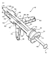
図1に、新型で改良された本発明に係るトグルボルト締付け具の全体を参照番号10で示している。トグルボルト締付け具10は、例えば、絵画、鏡、棚、照明、設備類、ブラケットのような様々な対象物を、スタッド部材により垂直又は水平に設置された乾式壁部材を備える乾式工法壁に設置するために、独特に改造されている。詳しく述べれば、トグルボルト締付け具10は、挿入用先端14にドリル構造を持つ管状トグルハウジングボディ12を備える。ドリル先端部14は、管状トグルハウジングボディ12の長手方向軸18に沿って設置された位置決め用スパイク用突起部材16と、弓形ドリル用刃面20とを備える。それゆえ、トグルハウジングボディ12を乾式壁部材内に挿入する時には、スパイク用突起部材16は、乾式工法壁構造体の乾式壁部材内に埋め込まれ、トグルハウジングボディ12が回転する回転中心位置を形成する。
In FIG. 1, a new and improved toggle bolt fastener according to the invention is indicated generally by the
長手方向軸18を中心としてトグルハウジングボディ12が回転する結果、ドリル先端部14のドリル用刃面20は、乾式壁部材に穴を明けながら進み、トグルハウジングボディ12を挿入することが可能となり、トグルハウジングボディ12は、乾式壁部材を突き刺し通過して伸びる。長手方向軸18を中心としてトグルハウジングボディ12を回転させるため、ドリル先端部14の反対側のトグルハウジングボディ12の端にはフランジ型頭部22が備えられている。そして、フランジ型頭部22は、例えばフィリップス社製ねじ回しあるいは類似の工具のような、適切な回転具を受入れるための実質上X字形の凹部を備えている。更に、比較的粗いねじ部26が、フランジ型頭部22の付近でトグルハウジングボディ12の外周に形成されている。こういう方式で、トグルハウジングボディ12が、乾式壁部材内に挿入され装着される時、トグルハウジングボディ12は、乾式壁部材内でねじ係合し、乾式壁部材内で適切に据付けられ保持される。この時、トグルハウジングボディ12のフランジ型頭部22は、乾式工法壁構造体の乾式壁部材の前面(外面)と実質上同一面に設置される。
As a result of the
更に、管状トグルハウジングボディ12は、ボディ12の正反対に対向する第1の壁部分に形成されている、第1の対の長手方向(軸方向)溝28、30を備えている。一対のトグル翼部材(クランプ留めトグル部材)32、34はそれぞれ、管状トグルハウジングボディ12の内側に設置されているナット部材36に装着されている。このようにトグル翼部材32、34がナット部材36に装着されている結果、一対のトグル翼部材32、34が、径内側に収縮する状態(位置)と径外側へ伸長する状態(位置)との間を動くように、トグル翼部材32、34は、ボディ12の正反対に対向する第1の壁部分に形成された第1の対の細長対向溝28、30を、通過するように改造されている。従来型では、一対のトグル翼部材32、34は、適切な旋回支持軸(図示せず)に回転可能に装着されており、一対のトグル翼部材32、34が設置される共通の平面に垂直な軸中心に回転可能に設置されている。そしてコイルスプリング部材が旋回支持軸(図示せず)の1つに装着され、コイルスプリング部材の外側に伸びる脚部がそれぞれ一対のトグル翼部材32、34に作用上係合し、図示のように実質上V形に形成される、一対のトグル翼部材32、34が径外側へ伸長する状態(位置)に向かって付勢する。
In addition, the tubular
ボディ12の正反対に対向する第1の壁部分に形成された第1の対の長手方向(軸方向)溝28、30に加えて、第2の対の長手方向(軸方向)溝42、44が、同様にボディ12の正反対に対向する第2の壁部分に形成されている。第2の対の長手方向(軸方向)溝42、44が、ボディ12の正反対に対向する第2の壁部分に形成されるように、ボディ12の正反対に対向する第1の壁部分に形成された第1の対の長手方向(軸方向)溝28、30との間に実際上、それぞれ置かれていることに注意すべきである。その結果、第1の対の長手方向(軸方向)溝28、30と第2の対の長手方向(軸方向)溝42、44は、周上で90°ずつ間隔を置いて互いに離れて、かわるがわる互いに配置される。ナット部材36は、係合スクリュ48をボディ12内へ軸方向に挿入する時、係合スクリュ48の雄ねじ軸部が係合する、軸方向雌ねじ穴46を持つ。係合スクリュ48の雄ねじ軸部が雌ねじ穴46と係合することにより、トグル翼部材32、34が、乾式壁部材の後面に係合する結果、トグルボルト締付け具10を、確実に乾式壁部材に固定することができる。そうして、周知の方法で、対象物を確実に乾式壁部材に固定することができる。
In addition to a first pair of longitudinal (axial)
更に、本発明においては、いくつかの重要な作用上の相互関係を達成するために、トグルボルト締付け具10は、独特で新規な構造を備える。例えば、雄ねじスクリュ48がナット部材36の雌ねじ穴46と対になってねじ係合するように改造されている場合、雄ねじスクリュ48は、ナット部材36の雌ねじ穴46に対して本質的に一直線上にあり同軸であることである。更に、ボディ12内でナット部材36が要求長手方向直線移動を生じるよう、ねじスクリュ48が雌ねじ穴46とねじ係合していることである。更に、トグル翼部材32、34と一緒のナット部材36は、ボディ12上で常に保持されていることである。
Furthermore, in the present invention, the
更に、ナット部材36は、正反対に対向して径方向に外側に伸びる、一対の耳状突起部材50を備える。図1では突起部材50の1つが見えている。図1に示すように、耳状突起部材50は、第2の対の長手方向(軸方向)溝42、44を通過して突き出し、それぞれ溝により摺動自在に設置されている。このように、耳状突起部材50は、ボディ12のフランジ型頭部22に向かったり離れたりするナット部材36とこれに装着されたトグル翼部材32、34の長手方向直線移動(これにより、トグルボルト締付け具10の乾式壁との係合及び係合解除の機能が達成可能となる)に一致して、ナット部材36がボディ12内で長手方向(軸方向)に動く時、ボディ12内でナット部材36を摺動自在に案内する手段としてのみならず、耳状突起部材50と第2の対の長手方向(軸方向)溝42、44との間の相互協働作用により、ボディ12に対するナット部材36の相対的回転が防止される。加えて、トグル翼部材32、34が、ボディ12の正反対に対向する第1の壁部分に形成された第1の対の長手方向(軸方向)対向溝28、30を通過して伸びるという点においては、耳状突起部材50が同様に、ボディ12の正反対に対向する第2の壁部分に形成された第2の対の長手方向(軸方向)溝42、44を通過して伸びるし、対向配置された第2の対の長手方向(軸方向)溝42、44は、それぞれ閉鎖端部(終端部)43、45を持つということにも注意すべきである。このことにより、トグル翼部材32、34と一緒のナット部材36は、ボディ12内で、いわば捕獲状態にされて、常に保持されることとなる。
Furthermore, the
更に、ナット部材36の外径は、管状トグルハウジングボディ12内に形成された穴の内径よりわずかに小さくなっており、これにより、ナット部材36は、第2の対の長手方向(軸方向)溝42、44を通過して外側へ伸びる耳状突起部材50により案内されながら、ボディ12内を長手方向(軸方向)に自在に動くことができる。そして、第2の対の長手方向(軸方向)溝42、44の閉鎖端部(終端部)により制限されるので、ナット部材36は、長手方向軸18に対する同軸位置から外れたり、一緒に係合しているねじスクリュ48から外れたりすることは不可能となる。従って、ねじスクリュ48が、長手方向軸18上に置かれる時、ナット部材36の雌ねじ穴46は、常に、ねじスクリュ48と同軸で一直線上にある。このように、ねじスクリュ48が、ナット部材36の雌ねじ穴46との係合のためトグルハウジングボディ12のフランジ型頭部22を通過して挿入される時、ナット部材36の雌ねじ穴46に対するねじスクリュ48の同軸度は、常に保証される。
Further, the outer diameter of the
更に、最も重要なことであるが、ねじスクリュ48が回される時のトグル翼部材32、34と一緒のナット部材36のねじスクリュ48上の直線的移動は、もちろん同様に保証される。従って、ねじスクリュ48とナット部材36との適切なねじ締結、及びトグル翼部材32、34と一緒のナット部材36のねじスクリュ48上の直線的移動の点で、外側へ伸びるトグル翼部材32、34が、乾式壁部材の後側(内側)へ接近する場合、トグル翼部材32、34は、乾式壁部材の後側(内側)と適切、確実に締結されることが可能となり、乾式壁部材上の特定対象物が確実に固定される。
Moreover, most importantly, the linear movement of the
図1に更に示すように、トグルハウジングボディ12は更に、長手方向(軸方向)に互い違いに間隔を置いたトグル収縮用スリーブ52、54を備える。トグル収縮用スリーブ52、54のそれぞれは、半円筒形のスリーブ構造となっており、このような半円筒形のスリーブ構造52、54は、軸18に対して正反対に対向する、管状トグルハウジングボディ12の壁部に一体形成されている。半円筒形のスリーブ構造52、54は、ドリル面20の後部であって、第2の対の長手方向(軸方向)溝42、44の端部の付近の軸上での位置に配置されている。従って、半円筒形のスリーブ構造52、54は、トグルハウジングボディ12に備えられており、耳状突起部材50と第2の対の長手方向(軸方向)溝42、44の相互作用により案内される結果、ナット部材36がドリル先端部14に向かって直線移動する時、スプリング付勢されたトグル翼部材32、34のそれぞれに作用上係合する。トグル翼部材32、34が半円筒形のスリーブ構造52、54に作用上係合する時、すなわちナット部材36がドリル先端部14に向かって直線移動する時、トグル翼部材32、34は、スプリング部材38、40の付勢力に対向して収縮状態になるよう径方向で内側に収縮させられ、収縮位置に保持される。そして、トグル翼部材32、34は、半円筒形のスリーブ構造52、54との作用上の係合が解除される時、すなわちナット部材36がフランジ型頭部22に向かってその付近に設置された時、スプリング部材38、40の付勢力により、トグル翼部材32、34は、径方向に外側へ開いて、拡張状態になることができる。
As further shown in FIG. 1, the
本発明に係る様々な構造上の特徴や、新型で改良されたトグルボルト締付け具10の構成要素について述べたが、本発明に係るトグルボルト締付け具10の作用サイクルをこれから述べる。トグルボルト締付け具10を最初に乾式壁部材に取付けようとする時、ナット部材36は、トグルハウジングボディ12の前端部に置かれる。トグル翼部材32、34は、ナット部材36により、半円筒形の収縮用スリーブ部材52、54に当接し、径方向で内側に向けられ、径方向収縮位置(状態)に収納される。更に、管状トグルハウジングボディ12は、ねじスクリュ48はまだ挿入されておらず、トグルボルト締付け具10の取付け予定位置に、位置決め用スパイク突起部材16を乾式壁部材の外面(前面)に接触して、取付けられる。フィリップス社製ねじ回しあるいは回転具内に取付けられる同様に構成された工具が、トグルハウジングボディ12のフランジ型頭部22に形成された実質上X字形の凹部24に挿入され、フィリップス社製ねじ回しあるいは回転具内に取付けられる同様に構成された工具により、トグルハウジングボディ12が長手軸18の回りを回転させられ、ドリル先端部14の弓形ドリル切れ刃20が、乾式壁部材内にトグルハウジングボディ12を挿入できるように、乾式壁部材に穴を明ける。
Having described various structural features according to the present invention and components of the new and improved
更に、トグルハウジングボディ12が、乾式壁部材内にドリルで明けられた穴を実質上貫通して挿入される時、トグルハウジングボディ12の粗いねじ部26は、乾式壁部材と係合し、更にトグルハウジングボディ12は回転を続ける。ねじ部26は、ボディ12が乾式壁部材内に完全に挿入されフランジ型頭部22が乾式壁部材の外面(前面)に同一面で着座するまで、乾式壁部材にねじ込まれる。この時点で、ねじスクリュ48がトグルハウジングボディ12の中へ挿入され、ねじスクリュ48の前端部がナット部材36の雌ねじ穴46と出会うこととなる。ナット部材36がトグルハウジングボディ12と同軸であるという点と、ねじスクリュ48の外径がトグルハウジングボディ12の穴の内径よりもわずかに小さいことから、雄ねじスクリュ48の前端部は、容易かつ正確に、ナット部材36の雌ねじ穴46と同軸となり係合することとなる。
Further, when the
引き続いて、ねじスクリュ48は、ナット部材36とねじ係合しているので、図1に示すように、ねじスクリュ48が時計方向に回転し、径方向に外側へ伸びる耳状突起部材50と、ボディ12の壁部分に正反対に対向して形成された第2の対の長手方向(軸方向)溝42、44との相互協働作用(この作用により、ナット部材36は、ボディ12に対して回転できなくなる)とにより、ナット部材36は、ボディ12のフランジ型頭部22に向かって長手方向(軸方向)に直線移動をする。従って、ナット部材36が、ボディ12の内部に沿って十分な距離を直線移動した時、トグル翼部材32、34は、半円筒形の収縮用スリーブ部材52、54内の収縮非作用位置(この位置ではトグル翼部材32、34は長手軸18と実質上平行に設置されている)から徐々に現れ、スプリング端部38、40は、トグル翼部材32、34を径方向に伸長する位置(展開状態)へ付勢する。
Subsequently, since the
ナット部材36が、ボディ12の内部に沿って一定の距離を直線移動した時、トグル翼部材32、34は、半円筒形の収縮用スリーブ部材52、54から完全に現れ、トグル翼部材32、34は、伸長作用位置に置かれる。最終的に、ねじスクリュ48は、時計方向に更に回転し、ナット部材36は、トグル翼部材32、34が乾式壁部材の後面(内面)にクランプ留めされるまで、ボディ12のフランジ型頭部22に向かって長手方向(軸方向)に直線移動をする。ねじスクリュ48の回転は、結果的にナット部材36の直線移動を生じさせて、もちろん、トグル翼部材32、34を乾式壁部材の後面(内面)に十分に完全にしっかりと締結するまで、続行される。このことにより、乾式壁部材に取付けられる特定対象物は事実上、乾式壁部材に確実に固定される。
When the
逆に、トグルボルト締付け具10が、前述のように乾式壁部材に取付けられた後に、乾式壁部材から取外される場合には、結果的にはトグルボルト締付け具10は再使用可能であるが、ねじスクリュ48は、逆の反時計回りに回転させられる。径方向に外側へ伸びる耳状突起部材50と、ボディ12の壁部分に正反対に対向して形成された第2の対の長手方向(軸方向)溝42、44との相互協働作用により、ナット部材36がボディ12に対して回転できなくなるので、ナット部材36がボディ12のフランジ型頭部22から離れて後退するように、ねじスクリュ48は、ナット部材36に対して長手方向(軸方向)に直線移動をする。ねじスクリュ48の回転はナット部材36に対して反時計回りに、ナット部材36が再びねじスクリュ48の前端部に位置するまで続行される。そうすると、ねじスクリュ48とナット部材36の組合せ体は、ボディ12の内部で、ボディ12のドリル先端部14に向かって、長手方向に移動可能となる。ねじスクリュ48とナット部材36の組合せ体は、ボディ12の内部で、ボディ12のドリル先端部14に向かって、長手方向に移動する結果、ナット部材36は、第1のトグル収縮用スリーブ52に接近し、トグル翼部材32が、スリーブ52により、スプリング端部材38の付勢力に対抗して内側に片寄せられ始める。ナット部材36は、ボディ12のドリル先端部14に向かって直線移動を続けるので、第2のトグル収縮用スリーブ54に接近し、トグル翼部材34が、スリーブ54により、同様に、スプリング端部材40の付勢力に対抗して内側に片寄せられ始める。
Conversely, if the
前記の作用に引き続き、トグル翼部材32、34が完全に収縮状態(位置)に移動するように、ナット部材36が完全に半円筒形の収縮用スリーブ部材52、54内に一旦収まった時には、ねじスクリュ48は、ナット部材36から完全に外れ、ボディ12から取外され、乾式壁部材に取付けられた特定対象物を取外すことが可能となる。その時、フィリップス社製ねじ回しあるいは類似の工具をトグルハウジングボディ12のフランジ型頭部22の凹部24にはめ込み、ボディ12と乾式壁部材との係合を解除しボディ12を乾式壁部材から引抜くことが可能となる。そのとき、トグルボルト締付け具10は、乾式壁に異なった対象物を取付けるために再使用可能である。
Subsequent to the above action, when the
図2ないし図5に、本発明に係るトグル組立品の変形例を有するトグルボルト締付け具の変形例を示す。これは、同様に、乾式壁内で使用するのに適する。図3ないし図5に示すトグルボルト締付け具110は、以下に手短く述べる部分を除き、図1に示すトグルボルト締付け具10と実質上同じである。従って、トグルボルト締付け具110の詳細な説明とその作用は省略する。すなわち、トグルボルト締付け具110に関する記述は、トグルボルト締付け具10の構造上の特徴と異なるもしくは追加される特徴に関するもののみとする。トグルボルト締付け具110の様々な特徴のある構造部材は、トグルボルト締付け具10で使用されている構造部材の参照番号と、100番台を使用して、類似の参照番号を付している。
2 to 5 show a modified example of the toggle bolt fastener having a modified example of the toggle assembly according to the present invention. This is likewise suitable for use in drywall. The toggle
図2に示すように、トグル組立品は、従来のV字形を互いに形成するように、ナット部材136上で互いに回転可能に装着されたトグル翼部材132、134を備えている。ナット部材136は、軸中心に雌ねじ穴146を備えている。図1に示すナット部材36と比較してナット部材136の変形された構造的特徴として、ナット部材136の環状ボディ部は、環状ボディ部から離れて反対方向へ外側へ伸びる一対の正反対に方向付けられた突起部材160、162を持つ。図2ないし図5から分かるように、このような突起部材160、162は、いくつかの機能を持つ。例えば、図2に最も良く表されているが、突起部材160、162は、トグル翼部材132、134がこの部材上で互いに回転可能に装着される耳部材としての機能を持つ。更に、突起部材162は、例えば、コイルスプリング部材のコイル体中心164が装着される支持部材としての機能を持つ。反対方向に伸びるスプリング端部138、140は、トグル翼部材132、134とそれぞれ係合するために前記コイル体中心164から外側へ伸びている。更に、図3ないし図5から分かるように、突起部材160、162は、図1に示すナット部材36のリブ状突起部材50に替わるものであり、軸方向(長手方向)に伸びる溝142、144から外側に突き出している。又、トグル翼部材132、134の収縮状態(位置)が図3に明瞭に示されている。一方、逆に、トグル翼部材132、134の外側への伸長状態(位置)が図4に明瞭に示されている。最後に、乾式壁部材168と係合可能にトグル翼部材132、134が外側へ伸長している状態(位置)が図5に示されている。従って、ねじスクリュ148のナット部材136との完全なねじ締結により、トグルボルト締付け具110は、乾式壁部材168に固定される。特に、新型で改良された本発明に係るトグルボルト締付け具10、110を使用すると、引抜き抵抗は、従来型のものより25%程度向上可能であることが、試験により証明された。
As shown in FIG. 2, the toggle assembly includes
このように、本発明に基づいて、ねじスクリュと、トグル部材が回転可能に装着されたナット部材との同軸度を確保する構造を備える新型で改良されたトグルボルト締付け具が提供される。このような方法で、ねじスクリュとナット部材との間の適切なねじ締結が同様に確保され、ナット部材に対するねじスクリュの回転の結果として、ナット部材がトグルハウジングボディに沿って適切に直線移動をし、これによってトグル翼部材が乾式壁部材の後面(内面)に確実に固定される。更に、この構造により、トグルボルト締付け具を、トグルボルト締付け具の全構成部品(例えば、ナット部材とこれに回転可能に装着したトグル翼部材)と共に乾式壁部材に取付けた後に、トグルボルト締付け具を乾式壁部材から取外すことが可能となる。 Thus, based on the present invention, there is provided a new and improved toggle bolt tightener having a structure that ensures the coaxiality of a screw screw and a nut member to which the toggle member is rotatably mounted. In this way, proper screw fastening between the screw screw and the nut member is likewise ensured, and as a result of the rotation of the screw screw relative to the nut member, the nut member is properly linearly moved along the toggle housing body. Thus, the toggle blade member is securely fixed to the rear surface (inner surface) of the dry wall member. Further, according to this structure, the toggle bolt fastener is attached to the dry wall member together with all the components of the toggle bolt fastener (for example, the nut member and the toggle blade member rotatably attached thereto), and then the toggle bolt fastener is attached. Can be removed from the dry wall member.
本発明に関して多くの変形例やバリエーションが派生することは、上記内容を考慮すると、明白である。それゆえ、上記詳細な説明とは別な方式により、特許請求の範囲内で本発明が実施可能であることが理解されねばならない。 It is clear that many variations and variations are derived from the present invention in view of the above contents. Therefore, it should be understood that the invention can be practiced within the scope of the claims in a manner different from the detailed description described above.
Claims (22)
長手軸を形成して前記パネル部材内に取付けられるトグルハウジングボディと、
前記トグルハウジングボディに対向して配置された第1および第2の対の側壁部分に各々形成された、長手方向に伸びる第1および第2の対の溝と、
前記トグルハウジングボディの前記長手軸に沿って前記トグルハウジングボディ内に移動可能に装着されるナット部材と、
前記トグルハウジングボディを前記パネル部材内に挿入しかつ前記パネル部材から取外すことを可能にするためにトグル手段が前記トグルハウジングボディの内部に実質上収納される第1非作用位置と、前記パネル部材内に取付けられた前記トグルハウジングボディを固定するために前記トグル手段が前記トグルハウジングボディに対向して配置された前記第1の対の側壁部分に形成された前記第1の対の溝を通過して外側へ伸張する第2作用位置との間を動くための前記ナット部材に装着されるトグル手段と、
対象物を繰り返し前記パネル部材に取付けるため前記トグルボルト締付け具を再使用すべく、前記トグルボルト締付け具を前記パネル部材に取付けたり取外したりすることが繰り返し可能になるように、前記トグル手段を前記第1非作用位置と前記第2作用位置との間で繰り返し移動可能にするように、前記トグルハウジングボディの前記長手軸に沿った前記ナット部材の移動位置次第で、前記トグル手段が前記第2作用位置に向かって外側へ伸張したり、前記第1非作用位置に向かって内側へ収縮したりする、ことを可能にする、前記トグルハウジングボディに装着されるスリーブ手段と、
前記トグルハウジングボディに対する前記ナット部材の回転運動を防止し、これにより、ねじ締付け具が前記トグルハウジングボディの前記長手軸の回りを回転するとき、前記ナット部材が前記トグルハウジングボディの前記長手軸に沿って直線移動可能となるように、かつ前記ねじ締付け具と前記ナット部材のねじ係合を確保するように、前記トグルハウジングボディに対向して配置された前記第2の側壁部分に形成された前記第2の対の溝を通過して外側へ伸張する、前記ナット部材に形成された耳状突起手段と、
を備えることを特徴とする、トグルボルト締付け具。 A toggle bolt fastening tool for attaching an object to a panel member,
A toggle housing body that forms a longitudinal axis and is mounted within the panel member;
First and second pairs of longitudinally extending grooves formed in first and second pairs of side wall portions disposed opposite the toggle housing body;
A nut member movably mounted in the toggle housing body along the longitudinal axis of the toggle housing body;
A first non-operating position in which toggle means is substantially housed within the toggle housing body to allow the toggle housing body to be inserted into and removed from the panel member; and the panel member The toggle means passes through the first pair of grooves formed in the first pair of side wall portions disposed opposite the toggle housing body for securing the toggle housing body mounted therein. And toggle means attached to the nut member for moving between a second working position extending outwardly ,
The toggle means is arranged so that it is possible to repeatedly attach and remove the toggle bolt fastener to the panel member in order to reuse the toggle bolt fastener to repeatedly attach an object to the panel member. Depending on the position of movement of the nut member along the longitudinal axis of the toggle housing body, the toggle means is adapted to move the second means so that it can be repeatedly moved between the first non-acting position and the second acting position . Sleeve means attached to the toggle housing body that allows the outer housing to extend outwardly toward the working position and to shrink inward toward the first non-working position ;
Preventing rotational movement of the nut member relative to the toggle housing body, so that when the screw fastener is rotated about the longitudinal axis of the toggle housing body, the nut member is in contact with the longitudinal axis of the toggle housing body. Formed on the second side wall portion arranged to face the toggle housing body so as to be linearly movable along and to ensure screw engagement between the screw fastener and the nut member. Ear-like projection means formed on the nut member extending outwardly through the second pair of grooves ;
A toggle bolt fastener, comprising:
前記トグルハウジングボディは、前記長手軸を形成する管形状体を有し、
前記ナット部材は、前記トグルハウジングボディ内で移動可能であることを特徴とする、トグルボルト締付け具。 The toggle bolt fastener according to claim 1,
It said toggle housing body has a tubular shaped body which forms the longitudinal axis,
A toggle bolt fastening tool, wherein the nut member is movable in the toggle housing body.
前記トグル手段は、一対のトグル翼部材が、前記トグルハウジングボディの前記長手軸に対して実質上平行になるように、径方向に互いに収縮している前記第1非作用位置と、前記一対のトグル翼部材が、実質上V字形を形成するように、径方向に伸長している前記第2作用位置との間で回転可能に前記ナット部材に装着された前記一対のトグル翼部材を備えていることを特徴とする、トグルボルト締付け具。 The toggle bolt fastener according to claim 2,
The toggle means includes a pair of toggle wing members, said to be substantially parallel to the longitudinal axis of the toggle housing body, and the first non-operating position are contracted with each other in the radial direction, of the pair toggle wing member, so as to form a substantially V-shaped, comprises a pair of toggle wing member mounted rotatably with said nut member between said second working position in which extends in the radial direction Toggle bolt fastener, characterized by
前記一対のトグル翼部材を前記第1非作用位置から前記第2作用位置に向かって伸張させるために、前記一対のトグル翼部材と作用上関連付けられているスプリング手段を、更に備えていることを特徴とする、トグルボルト締付け具。 The toggle bolt fastener according to claim 3,
The pair of toggle wing member in order to Shin Zhang toward the second operating position from the first inactive position, the spring means associated on the working and the pair of toggle wing member, that it comprises further Toggle bolt fastener.
前記スプリング手段は、前記ナット部材に装着されていることを特徴とする、トグルボルト締付け具。 The toggle bolt fastener according to claim 4,
The toggle bolt fastening tool, wherein the spring means is attached to the nut member.
前記トグル手段を前記第1非作用位置と前記第2作用位置との間で繰り返し移動可能にするために、前記トグルハウジングボディに装着される前記スリーブ手段は、
1対のトグル翼部材が前記第2伸張作用位置から前記第1収縮非作用位置へ移動するように、前記ナット部材に装着される1対のトグル翼部材を作用上係合させ、前記ナット部材を収容するために、前記管状トグルハウジングボディに固定して装着された1対のトグル収縮用スリーブ部材から成ることを特徴とする、トグルボルト締付け具。 The toggle bolt fastener according to claim 4 ,
In order to repeatedly move the toggle means between the first non-acting position and the second acting position, the sleeve means attached to the toggle housing body comprises:
A pair of toggle blade members mounted on the nut member are operatively engaged so that the pair of toggle blade members move from the second extension operation position to the first contraction non-operation position, and the nut member Toggle bolt fastening tool comprising a pair of toggle contraction sleeve members fixedly mounted on the tubular toggle housing body .
第1および第2の対の長手方向に伸びる溝が、一対のトグル翼部材が前記第1非作用位置と前記第2作用位置との間で動くことを可能にするため、前記管状トグルハウジングボディの正反対に対向する第1および第2の側壁部分に各々形成されており、周上で互いに90°離れた間隔に配置されていることを特徴とする、トグルボルト締付け具。 The toggle bolt fastener according to claim 3 ,
The tubular toggle housing body is configured to allow a first and second pair of longitudinally extending grooves to allow a pair of toggle wing members to move between the first non-operating position and the second operating position. A toggle bolt fastener, wherein the toggle bolt fastener is formed on first and second side wall portions that are opposite to each other and spaced apart from each other by 90 ° on the circumference .
前記トグルハウジングボディに対する前記ナット部材の回転運動を防止するために前記ナット部材に形成された前記耳状突起手段は、前記ナット部材に設置された径方向に外側に伸びる一対の耳状突起部材から成り、
前記一対の耳状突起部材は、前記トグルハウジングボディに対する前記ナット部材の回転運動を防止し、これにより、前記ねじ締付け具が前記トグルハウジングボディの前記長手軸の回りを回転するとき、前記ねじ締付け具によるねじ係合の結果として前記ナット部材が前記管状トグルハウジングボディの内部を前記管状トグルハウジングボディの前記長手軸に沿って直線移動可能となり、前記ねじ締付け具と前記ナット部材のねじ係合を確保するように、前記一対の耳状突起部材は、前記トグルハウジングボディの正反対に対向して配置された前記第2の側壁部分に形成された前記第2の対の長手方向に伸びる溝内に各々配置されることを特徴とする、トグルボルト締付け具。 The toggle bolt fastener according to claim 7,
The ear projection means formed on the nut member to prevent rotational movement of the nut member relative to the toggle housing body includes a pair of ear projection members extending outward in the radial direction installed on the nut member. Consisting of
The pair of lug members prevent rotational movement of the nut member relative to the toggle housing body, so that when the screw fastener rotates about the longitudinal axis of the toggle housing body, the screw fastening As a result of the screw engagement by the tool, the nut member can move linearly along the longitudinal axis of the tubular toggle housing body within the tubular toggle housing body, and the screw engagement between the screw fastener and the nut member can be achieved. In order to ensure, the pair of lug-shaped protrusion members are in grooves extending in the longitudinal direction of the second pair formed in the second side wall portion disposed oppositely opposite to the toggle housing body. Toggle bolt fasteners, each being arranged .
前記トグルハウジングボディは、予め決められた内径の穴を持ち、前記ナット部材が、前記トグルハウジングボディの前記穴の前記内径よりわずかに小さい予め決められた外径を有していることを特徴とする、トグルボルト締付け具。 The toggle bolt fastener according to claim 8 ,
The toggle housing body has a hole with a predetermined inner diameter, and the nut member has a predetermined outer diameter slightly smaller than the inner diameter of the hole of the toggle housing body. Toggle bolt tightener.
前記トグルハウジングボディは、前記ボディを前記ボディの長手軸回りに回転させる時、前記ボディのパネル部材内への挿入を容易にするよう前記ボディ自身により穴を明ける手段を前記ボディの第1の端部に形成していることを特徴とする、トグルボルト締付け具。 The toggle bolt fastener according to claim 2,
The toggle housing body has means for drilling a hole in the body itself to facilitate insertion of the body into a panel member when the body is rotated about the longitudinal axis of the body. Toggle bolt fastener, characterized in that it is formed on the part.
前記トグルハウジングボディが前記パネル部材内に完全に挿入された時、前記トグルハウジングボディを前記パネル部材と実質上同一面となる部材として取付けるために、To attach the toggle housing body as a member that is substantially flush with the panel member when the toggle housing body is fully inserted into the panel member,
前記トグルハウジングボディは、前記トグルハウジングボディの第2の反対側端部に形成されたフランジ型頭部を有しており、The toggle housing body has a flange-type head formed at a second opposite end of the toggle housing body;
前記トグルハウジングボディの前記自身により穴を明ける手段が前記パネル部材内に穴を明け、前記穴を通過して前記トグルハウジングボディが挿入されて前記パネル部材内に装着されることを可能にするために、前記長手軸回りに前記トグルハウジングボディを回転させ、この回転を容易にするために、凹部手段が、回転具を受入れるため前記トグルハウジングボディの前記フランジ型頭部内に形成されていることを特徴とする、トグルボルト締付け具。To allow the means of drilling holes in the toggle housing body by itself to drill holes in the panel member, allowing the toggle housing body to be inserted and mounted in the panel member through the holes. Further, in order to rotate the toggle housing body around the longitudinal axis and to facilitate the rotation, a recess means is formed in the flange-type head of the toggle housing body for receiving the rotating tool. Toggle bolt fastener.
長手軸を形成して前記パネル部材内に取付けられるトグルハウジングボディと、A toggle housing body that forms a longitudinal axis and is mounted within the panel member;
前記トグルハウジングボディに対向して配置された第1および第2の対の側壁部分に各々形成された、長手方向に伸びる第1および第2の対の溝と、First and second pairs of longitudinally extending grooves formed in first and second pairs of side wall portions disposed opposite the toggle housing body;
前記トグルハウジングボディ内に移動可能に装着されるナット部材であって、前記ナット部材は、ねじ締付け具とねじ係合される雌ねじを有し、これにより、前記ねじ締付け具が前記トグルハウジングボディの前記長手軸の回りを回転する時、前記ナット部材が前記トグルハウジングボディの前記長手軸に沿って直線移動可能となるナット部材と、A nut member movably mounted within the toggle housing body, the nut member having an internal thread that is threadedly engaged with a screw fastener, whereby the screw fastener is mounted on the toggle housing body; A nut member that allows the nut member to move linearly along the longitudinal axis of the toggle housing body when rotating about the longitudinal axis;
前記トグルハウジングボディを前記パネル部材内に挿入しかつ前記パネル部材から取外すことを可能にするためにトグル手段が前記トグルハウジングボディの内部に実質上収納される第1非作用位置と、前記パネル部材内に取付けられた前記トグルハウジングボディを固定するために前記トグル手段が前記トグルハウジングボディに対向して配置された前記第1の対の側壁部分に形成された前記第1の対の溝を通過して外側へ伸張する第2作用位置との間を動くための前記ナット部材に装着されるトグル手段と、A first non-operating position in which toggle means is substantially housed within the toggle housing body to allow the toggle housing body to be inserted into and removed from the panel member; and the panel member The toggle means passes through the first pair of grooves formed in the first pair of side wall portions disposed opposite the toggle housing body for securing the toggle housing body mounted therein. And toggle means attached to the nut member for moving between a second working position extending outwardly,
対象物を繰り返し前記パネル部材に取付けるため前記トグルボルト締付け具を再使用すべく、前記トグルボルト締付け具を前記パネル部材に取付けることおよび取外すことが繰り返し可能になるように、前記トグル手段を前記第1非作用位置と前記第2作用位置との間で繰り返し移動可能にするように、前記トグルハウジングボディの前記長手軸に沿った前記ナット部材の移動位置次第で、前記トグル手段が前記第2作用位置に向かって外側へ伸張し、あるいは前記第1非作用位置に向かって内側へ収縮する、ことを可能にする、前記トグルハウジングボディに装着されるスリーブ手段と、In order to reuse the toggle bolt fastener for re-attaching an object to the panel member, the toggle means is adapted to be able to be repeatedly attached to and removed from the panel member. Depending on the position of movement of the nut member along the longitudinal axis of the toggle housing body, the toggle means may move the second action so that it can be repeatedly moved between a non-acting position and the second acting position. Sleeve means attached to the toggle housing body allowing to extend outward toward a position or contract inward toward the first non-acting position;
前記トグルハウジングボディと作用上協働するために前記トグルハウジングボディに対向して配置された前記第2の側壁部分に形成された前記第2の対の溝を通過して外側へ伸張する、前記ナット部材に形成された耳状突起手段であって、前記トグルハウジングボディに対する前記ナット部材の回転運動を防止し、これにより、ねじ締付け具が前記トグルハウジングボディの前記長手軸の回りを回転する時、前記ナット部材が前記トグルハウジングボディの前記長手軸に沿って直線移動可能となり、前記ねじ締付け具と前記ナット部材の適切なねじ係合を確保するように、さらに、前記トグル手段が前記トグルハウジングボディに対して前記第1非作用位置または前記第2作用位置のいずれに配置されても、前記ナット部材の前記雌ねじが、前記トグルハウジングボディ内に形成された前記長手軸に対して常に同軸に配置される方式で、前記ナット部材が前記トグルハウジングボディ内に装着されるための耳状突起手段と、Extending outwardly through the second pair of grooves formed in the second sidewall portion disposed opposite the toggle housing body to operatively cooperate with the toggle housing body, Ear-like projection means formed on the nut member for preventing rotational movement of the nut member relative to the toggle housing body, whereby the screw fastener rotates around the longitudinal axis of the toggle housing body The toggle member further moves linearly along the longitudinal axis of the toggle housing body, and the toggle means further comprises a toggle housing to ensure proper screw engagement between the screw fastener and the nut member. The female screw of the nut member is disposed at either the first non-operating position or the second operating position with respect to the body. In a manner that is always disposed coaxially with serial the longitudinal axis formed in the toggle housing body, and lugs means for the nut member is mounted to said toggle housing body,
を備えることを特徴とする、トグルボルト締付け具。A toggle bolt fastener, comprising:
前記トグルハウジングボディは、前記長手軸を形成する管形状体を有し、The toggle housing body has a tubular body that forms the longitudinal axis;
前記ナット部材は、前記トグルハウジングボディ内で移動可能であることを特徴とする、トグルボルト締付け具。A toggle bolt fastening tool, wherein the nut member is movable in the toggle housing body.
前記トグル手段は、一対のトグル翼部材が、前記トグルハウジングボディの長手軸に対して実質上平行になるように、径方向に互いに収縮している前記第1非作用位置と、前記一対のトグル翼部材が、実質上V字形を形成するように、径方向に伸長している前記第2作用位置との間で回転可能に前記ナット部材に装着された一対のトグル翼部材を備えていることを特徴とする、トグルボルト締付け具。The toggle means includes a first non-operating position in which a pair of toggle wing members contract each other in a radial direction so that the pair of toggle wing members are substantially parallel to a longitudinal axis of the toggle housing body, and the pair of toggle members. The wing member includes a pair of toggle wing members mounted on the nut member so as to be rotatable with respect to the second action position extending in the radial direction so as to form a substantially V-shape. Toggle bolt fastener.
前記一対のトグル翼部材を前記第1非作用位置から前記第2作用位置に向かって伸長させるために、前記一対のトグル翼部材と作用上関連付けられているスプリング手段を、更に備えていることを特徴とする、トグルボルト締付け具。In order to extend the pair of toggle wing members from the first non-acting position toward the second acting position, further comprising spring means operatively associated with the pair of toggle wing members. A featured toggle bolt fastener.
前記スプリング手段は、前記ナット部材に装着されていることを特徴とする、トグルボルト締付け具。The toggle bolt fastening tool, wherein the spring means is attached to the nut member.
前記トグル手段を前記第1非作用位置と前記第2作用位置との間で繰り返し移動可能にするために、前記トグルハウジングボディに装着される前記スリーブ手段は、In order to repeatedly move the toggle means between the first non-acting position and the second acting position, the sleeve means attached to the toggle housing body comprises:
1対のトグル翼部材が前記第2作用拡張位置から前記第1非作用収縮位置へ移動されるように、前記ナット部材に装着される1対のトグル翼部材を作用上係合させ、前記ナット部材を収容するために、管状トグルハウジングボディに固定して装着された1対のトグル収縮用スリーブ部材を備えることを特徴とする、トグルボルト締付け具。A pair of toggle blade members mounted on the nut member are operatively engaged so that the pair of toggle blade members are moved from the second action expansion position to the first non-action contraction position, and the nut A toggle bolt fastener comprising a pair of toggle contraction sleeve members fixedly mounted to a tubular toggle housing body to accommodate the members.
第1および第2の対の長手方向に伸びる溝が、一対のトグル翼部材が前記第1非作用位置と前記第2作用位置との間で動くことを可能にするため、前記管状トグルハウジングボディの正反対に対向する第1および第2の側壁部分に各々形成されており、周上で互いに90°離れた間隔に配置されていることを特徴とする、トグルボルト締付け具。The tubular toggle housing body is configured to allow a first and second pair of longitudinally extending grooves to allow a pair of toggle wing members to move between the first non-operating position and the second operating position. A toggle bolt fastener, wherein the toggle bolt fastener is formed on first and second side wall portions that are opposite to each other and spaced apart from each other by 90 ° on the circumference.
前記ナット部材の前記雌ねじが、前記トグルハウジングボディ内に形成された前記長手軸に対して常に同軸に配置される方式で、前記ナット部材が前記トグルハウジングボディ内に装着されるように前記ナット部材に形成された前記耳状突起手段は、前記ナット部材に設置された径方向に外側に伸びる一対の耳状突起部材から成り、The nut member is mounted in the toggle housing body in such a manner that the female screw of the nut member is always arranged coaxially with respect to the longitudinal axis formed in the toggle housing body. The ear projection means formed on the nut member comprises a pair of ear projection members extending outward in the radial direction installed on the nut member,
前記ねじ締付け具が前記トグルハウジングボディの前記長手軸の回りを回転する時、前記ナット部材が前記トグルハウジングボディの前記長手軸に沿って直線移動するように、前記ナット部材が、前記トグルハウジングボディの前記長手軸に対して常に同軸に配置されることが確保され、これにより前記ねじ締付け具と前記ナット部材の適切なねじ係合を可能にするために、When the screw fastener rotates about the longitudinal axis of the toggle housing body, the nut member is configured to move linearly along the longitudinal axis of the toggle housing body. In order to ensure that it is always arranged coaxially with respect to the longitudinal axis of the screw, thereby enabling proper screw engagement of the screw fastener and the nut member,
前記一対の耳状突起部材は、前記トグルハウジングボディの正反対に対向して配置された前記第2の側壁部分に形成された前記第2の対の長手方向に伸びる溝内に各々配置されることを特徴とする、トグルボルト締付け具。The pair of lug projection members are respectively disposed in grooves extending in the longitudinal direction of the second pair formed in the second side wall portion disposed opposite to the toggle housing body. Toggle bolt fastener.
前記トグルハウジングボディは、前記ボディを前記ボディの長手軸回りに回転させる時、前記ボディのパネル部材内への挿入を容易にするよう前記ボディ自身により穴を明ける手段を前記ボディの第1の端部に形成していることを特徴とする、トグルボルト締付け具。The toggle housing body has means for drilling a hole in the body itself to facilitate insertion of the body into a panel member when the body is rotated about the longitudinal axis of the body. Toggle bolt fastener, characterized in that it is formed on the part.
前記トグルハウジングボディが前記パネル部材内に完全に挿入される時、前記トグルハウジングボディを前記パネル部材と実質上同一面部材として設置するために、In order to install the toggle housing body as a substantially flush member with the panel member when the toggle housing body is fully inserted into the panel member,
前記トグルハウジングボディは、前記トグルハウジングボディの第2の反対側端部に形成されたフランジ型頭部を有しており、The toggle housing body has a flange-type head formed at a second opposite end of the toggle housing body;
前記トグルハウジングボディの前記自身により穴を明ける手段が前記パネル部材内に孔を明け、前記孔を通過して前記トグルハウジングボディが挿入されて前記パネル部材内に装着されることを可能にするために、長手軸回りに前記トグルハウジングボディを回転することを容易にするように、The means for drilling a hole in the toggle housing body by itself to drill a hole in the panel member and allowing the toggle housing body to be inserted and mounted in the panel member through the hole; To facilitate rotation of the toggle housing body about the longitudinal axis,
凹部手段が、回転具を受入れるため前記トグルハウジングボディの前記フランジ型頭部内に形成されていることを特徴とする、トグルボルト締付け具。A toggle bolt clamp, characterized in that a recess means is formed in the flange-type head of the toggle housing body for receiving a rotating tool.
前記トグルハウジングボディは、予め決められた内径の穴を持ち、前記ナット部材が、前記トグルハウジングボディの前記穴の前記内径よりわずかに小さい予め決められた外径を有していることを特徴とする、トグルボルト締付け具。The toggle housing body has a hole with a predetermined inner diameter, and the nut member has a predetermined outer diameter slightly smaller than the inner diameter of the hole of the toggle housing body. Toggle bolt tightener.
Applications Claiming Priority (2)
| Application Number | Priority Date | Filing Date | Title |
|---|---|---|---|
| US10/653,957 US6884012B2 (en) | 2003-09-04 | 2003-09-04 | Heavy duty toggle bolt fastener assembly, and method of installing and removing the same |
| US10/653957 | 2003-09-04 |
Publications (3)
| Publication Number | Publication Date |
|---|---|
| JP2005083577A JP2005083577A (en) | 2005-03-31 |
| JP2005083577A5 JP2005083577A5 (en) | 2007-09-13 |
| JP5154739B2 true JP5154739B2 (en) | 2013-02-27 |
Family
ID=34136660
Family Applications (1)
| Application Number | Title | Priority Date | Filing Date |
|---|---|---|---|
| JP2004252427A Expired - Fee Related JP5154739B2 (en) | 2003-09-04 | 2004-08-31 | Toggle bolt fastener for heavy objects and method of disassembling |
Country Status (7)
| Country | Link |
|---|---|
| US (1) | US6884012B2 (en) |
| EP (1) | EP1512874A3 (en) |
| JP (1) | JP5154739B2 (en) |
| CN (1) | CN1598334B (en) |
| AU (1) | AU2004206991B2 (en) |
| CA (1) | CA2475643C (en) |
| TW (1) | TWI295710B (en) |
Families Citing this family (58)
| Publication number | Priority date | Publication date | Assignee | Title |
|---|---|---|---|---|
| US7922158B2 (en) | 2003-02-18 | 2011-04-12 | Truss Industry Production Systems, Inc. | Automatic truss jig setting system |
| CA2420722A1 (en) | 2003-03-04 | 2004-09-04 | Cobra Fixations Cie Ltee - Cobra Anchors Co. Ltd. | Wall mounted hook |
| CA2502044A1 (en) * | 2005-03-21 | 2006-09-21 | Cobra Fixations Cie Ltee. - Cobra Anchors Co. Ltd. | Anchor assembly for fastener |
| CA2502008A1 (en) | 2005-03-21 | 2006-09-21 | Cobra Fixations Cie Ltee - Cobra Anchors Co. Ltd. | Anchor with toggle for hollow walls |
| AU2005202700C1 (en) * | 2005-06-21 | 2006-07-06 | Glen Altoft | A Fastener |
| US7828501B2 (en) * | 2006-03-10 | 2010-11-09 | Moen Incorporated | Mounting mechanism |
| US20080132917A1 (en) * | 2006-12-04 | 2008-06-05 | Gregory Paul Mueller | Surgical instrument docking device |
| US8152038B2 (en) * | 2007-03-16 | 2012-04-10 | Illinois Tool Works Inc. | Nose assembly for a fastener driving tool |
| US8142479B2 (en) * | 2007-05-01 | 2012-03-27 | Spinal Simplicity Llc | Interspinous process implants having deployable engagement arms |
| US7815407B2 (en) * | 2007-09-14 | 2010-10-19 | Paul Kucharyson | Self-drilling anchor |
| GB0725363D0 (en) * | 2007-12-31 | 2008-02-06 | Pilon Jean | Hollow wall anchor |
| GB0809255D0 (en) * | 2008-05-21 | 2008-06-25 | Collins John R | Toggle bolt |
| CA2643664A1 (en) | 2008-10-30 | 2010-04-30 | Cobra Fixations Cie Ltee - Cobra Anchors Co. Ltd. | Wall-mounted hook |
| TWI356868B (en) * | 2008-11-13 | 2012-01-21 | Hannspree Inc | Connecting member |
| JP2012509093A (en) | 2008-11-18 | 2012-04-19 | コブラ フィクセイションズ シーアイイー エルティーイーイー−コブラ アンカーズ カンパニー リミテッド | Hook for hollow wall |
| US9757164B2 (en) | 2013-01-07 | 2017-09-12 | Spinal Simplicity Llc | Interspinous process implant having deployable anchor blades |
| US8945184B2 (en) * | 2009-03-13 | 2015-02-03 | Spinal Simplicity Llc. | Interspinous process implant and fusion cage spacer |
| US9861399B2 (en) | 2009-03-13 | 2018-01-09 | Spinal Simplicity, Llc | Interspinous process implant having a body with a removable end portion |
| US7861487B2 (en) * | 2009-05-18 | 2011-01-04 | Davinci Italia/Usa Group, Llc | Tile alignment and leveling device |
| USD635843S1 (en) | 2009-10-30 | 2011-04-12 | Cobra Fixations Cie. Ltee.-Cobra Anchors Co., Ltd. | Wall-mounted hook |
| USD636256S1 (en) | 2009-11-18 | 2011-04-19 | Cobra Fixations Cie. Ltee.-Cobra Anchors Co. Ltd. | Wall-mounted hook |
| CA133911S (en) | 2010-01-27 | 2011-02-03 | Cobra Fixations Cie Ltée Cobra Anchors Co Ltd | Wall anchor |
| CN102011781B (en) * | 2010-11-19 | 2016-03-30 | 海尔集团公司 | A kind of bolt arrangement and handling method thereof |
| SG182027A1 (en) * | 2010-12-30 | 2012-07-30 | Bin Juffri Irawan | Fastening device |
| US20140154028A1 (en) * | 2011-08-02 | 2014-06-05 | Chunguang Pei | Scisssors type expansion bolt |
| CN103452985B (en) * | 2013-08-20 | 2015-05-20 | 苏州欢颜电气有限公司 | Rivet capable of being rapidly assembled and disassembled |
| FR3019010B1 (en) * | 2014-03-28 | 2016-06-10 | Assi Meca Sa | DEVICE FOR FIXING A JEWEL, IN PARTICULAR AN EARRING. |
| CN104179773A (en) * | 2014-08-19 | 2014-12-03 | 江苏中寰卫星导航通信有限公司 | Fastening screw of satellite base |
| CN105114431B (en) * | 2015-07-31 | 2017-09-05 | 中色奥博特铜铝业有限公司 | A kind of fastening bolt for being used to fix copper foil testing machine |
| ES2957889T3 (en) * | 2016-03-17 | 2024-01-29 | Centrix Inc | Single-sided removable fastener with ultra-low stack height gripping range and methods of manufacturing and using the same |
| CN106523496A (en) * | 2016-06-02 | 2017-03-22 | 祁欣妤 | Double-sheet riveting device |
| US11105357B2 (en) | 2016-07-05 | 2021-08-31 | Grapplefix Limited | Fixing device |
| US10859106B1 (en) * | 2016-10-19 | 2020-12-08 | Daniel John Wagner | Detachable fastener |
| CA2989037A1 (en) | 2016-12-22 | 2018-06-22 | The Hillman Group, Inc. | Hollow wall anchor |
| CN106669060A (en) * | 2016-12-23 | 2017-05-17 | 东莞产权交易中心 | Safe support for assembly of air conditioner |
| US10865823B2 (en) * | 2017-02-01 | 2020-12-15 | Theodore Garfield | Metal channel anchor with enhanced holding strength |
| JP6945305B2 (en) * | 2017-02-15 | 2021-10-06 | Jfe建材株式会社 | Temporary fastening jig and temporary fastening method |
| CN106725061B (en) * | 2017-03-02 | 2022-05-27 | 泉州科牧智能厨卫有限公司 | Closestool cover plate fixing device |
| TWI632304B (en) * | 2017-06-03 | 2018-08-11 | 伍鐌科技股份有限公司 | Side fastening structure |
| GB201710671D0 (en) * | 2017-07-03 | 2017-08-16 | Gripple Ltd | Anchor arrangement |
| US11486432B2 (en) | 2018-11-29 | 2022-11-01 | The Hillman Group, Inc. | Anchor assembly with toggle |
| US11655837B2 (en) | 2018-11-29 | 2023-05-23 | Tlie Hillman Group, Inc. | Anchor assembly with toggle |
| CN109488675A (en) * | 2018-12-10 | 2019-03-19 | 重庆大学 | A kind of hinged bolt |
| CN109441925B (en) * | 2018-12-10 | 2023-09-29 | 重庆大学 | Unidirectional bolt with controllable expansion piece |
| CA3027635A1 (en) * | 2018-12-14 | 2020-06-14 | Cobra Fixations Cie Ltee - Cobra Anchors Co. Ltd. | Wall anchor with deformable expandable part |
| TR201820721A2 (en) * | 2018-12-27 | 2020-07-21 | Eczacibasi Yapi Gerecleri Sanayi Ve Ticaret Anonim Sirketi | A FIXING APPARATUS AND METHOD |
| GB2581539B (en) * | 2019-03-08 | 2021-03-03 | Goodenough Christopher | Wall fixing device |
| GB2584396B (en) * | 2019-05-02 | 2023-11-15 | Loadfix Ltd | A fixing device for securing an item to a wall |
| CN110904807B (en) * | 2019-11-26 | 2021-03-02 | 南通万航船舶设计有限公司 | Pin-connected panel passenger footbridge structure |
| CN111640540B (en) * | 2020-06-19 | 2021-09-07 | 北京朝阳隆华电线电缆有限公司 | Wire harness processing auxiliary device and using method thereof |
| EP4012198A1 (en) * | 2020-12-08 | 2022-06-15 | Xiamen Beewill Sanitary Co., Ltd. | Locking assembly |
| CN112663533B (en) * | 2020-12-18 | 2022-02-11 | 海宁金都新能源有限公司 | Road pile installation mechanism |
| CN113208452A (en) * | 2021-04-30 | 2021-08-06 | 广东美的厨房电器制造有限公司 | Cooking device's assembly structure and cooking device |
| CN216044797U (en) * | 2021-08-11 | 2022-03-15 | 中山市美图塑料工业有限公司 | Fastening assembly |
| CN114193375B (en) * | 2021-12-29 | 2023-12-29 | 重庆交通大学绿色航空技术研究院 | Reusable connecting and locking mechanism |
| CN114263671B (en) * | 2021-12-29 | 2024-01-19 | 重庆交通大学绿色航空技术研究院 | Connection locking mechanism convenient to dismantle |
| CN114673722B (en) * | 2022-03-23 | 2023-07-07 | 杭州键嘉医疗科技股份有限公司 | Quick installation connecting device |
| CN115013411A (en) * | 2022-05-25 | 2022-09-06 | 宁波华力兴紧固件有限公司 | High-adaptability anti-loosening fastener |
Family Cites Families (21)
| Publication number | Priority date | Publication date | Assignee | Title |
|---|---|---|---|---|
| US1316857A (en) * | 1919-09-23 | Fredebick schilling | ||
| US2024871A (en) * | 1935-06-13 | 1935-12-17 | Edwin R Parsons | Toggle bolt and sleeve |
| US2398220A (en) * | 1944-11-28 | 1946-04-09 | Rawlplug Company Inc | Toggle lock |
| US2908196A (en) * | 1957-07-25 | 1959-10-13 | Alex A Apfelzweig | Toggle bolt |
| DK105081C (en) * | 1964-02-24 | 1966-08-15 | Aackersberg Mortensen | Fastening means. |
| US3285118A (en) * | 1965-01-08 | 1966-11-15 | Edward L Elkins | Anchor bolt with spring actuated toggle head |
| SE386383B (en) * | 1973-10-12 | 1976-08-09 | Asea Ab | TUBE PRESSURE FOR HYDROSTATIC EXTENSION WITH SUBSTRATE PISTON IN PRESSURE CHAMBER |
| US4116104A (en) * | 1977-04-15 | 1978-09-26 | Arvest Gethner Kennedy | Toggle bolt wing nut retainer |
| US4449873A (en) * | 1982-02-25 | 1984-05-22 | Illinois Tool Works Inc. | Fastener for attaching articles to a penetrable surface |
| US4822226A (en) * | 1983-08-08 | 1989-04-18 | Kennedy Arvest G | Wing nut retainer and extractor |
| US4601625A (en) * | 1984-05-11 | 1986-07-22 | Illinois Tool Works Inc. | Self drilling threaded insert for drywall |
| JPS62181369U (en) * | 1986-05-09 | 1987-11-17 | ||
| US4764065A (en) * | 1987-05-06 | 1988-08-16 | Johnson Carl D | Wall anchor |
| JPH0173513U (en) * | 1987-11-04 | 1989-05-18 | ||
| JPH0229310U (en) * | 1988-08-12 | 1990-02-26 | ||
| US5067864A (en) * | 1990-07-27 | 1991-11-26 | Illinois Tool Works Inc. | Self-drilling fastener for plasterboard wall |
| US5226768A (en) * | 1991-07-01 | 1993-07-13 | Speer Lane L | Anchor bolt construction |
| FR2684146B1 (en) * | 1991-11-22 | 1994-02-11 | Prospection Inventions Technique | SINGLE PIECE MOLDED ROCKER ANCHOR AND MOLDING METHOD THEREOF. |
| AUPO629297A0 (en) * | 1997-04-21 | 1997-05-15 | W.A. Deutsher Pty Ltd | Threaded anchor |
| JP2000356209A (en) * | 1999-06-16 | 2000-12-26 | Haruo Nakamura | Anchor for cellular concrete |
| US6435789B2 (en) * | 1999-12-21 | 2002-08-20 | Powers Fasteners | Self drilling swivel toggle anchor |
-
2003
- 2003-09-04 US US10/653,957 patent/US6884012B2/en not_active Expired - Lifetime
-
2004
- 2004-07-21 TW TW093121801A patent/TWI295710B/en not_active IP Right Cessation
- 2004-07-21 CA CA002475643A patent/CA2475643C/en not_active Expired - Fee Related
- 2004-08-17 CN CN200410058208.5A patent/CN1598334B/en not_active Expired - Fee Related
- 2004-08-31 JP JP2004252427A patent/JP5154739B2/en not_active Expired - Fee Related
- 2004-09-01 AU AU2004206991A patent/AU2004206991B2/en active Active
- 2004-09-03 EP EP04292129A patent/EP1512874A3/en not_active Withdrawn
Also Published As
| Publication number | Publication date |
|---|---|
| EP1512874A3 (en) | 2006-04-19 |
| EP1512874A2 (en) | 2005-03-09 |
| US20050053444A1 (en) | 2005-03-10 |
| CA2475643A1 (en) | 2005-03-04 |
| TW200510646A (en) | 2005-03-16 |
| TWI295710B (en) | 2008-04-11 |
| AU2004206991B2 (en) | 2006-06-01 |
| US6884012B2 (en) | 2005-04-26 |
| CN1598334A (en) | 2005-03-23 |
| AU2004206991A1 (en) | 2005-03-24 |
| CA2475643C (en) | 2009-04-28 |
| CN1598334B (en) | 2010-05-12 |
| JP2005083577A (en) | 2005-03-31 |
Similar Documents
| Publication | Publication Date | Title |
|---|---|---|
| JP5154739B2 (en) | Toggle bolt fastener for heavy objects and method of disassembling | |
| JP2005083577A5 (en) | ||
| US20020144574A1 (en) | Combination wedge-type fastener and installing tool | |
| US20050036844A1 (en) | Clamping Device for Hexagon Bits | |
| AU2020101459A4 (en) | Telescoping boom wear pad improvements | |
| US10300588B2 (en) | Method of setting a drop-in anchor | |
| AU2017225135A1 (en) | Ground engaging tool locking system | |
| AU2023200835A1 (en) | Releasable Fastener | |
| US11105356B2 (en) | Drop-in anchor setting tool | |
| GB2477361A (en) | Radially expandable connector | |
| BR0111560B1 (en) | screwdriver. | |
| RU2766629C2 (en) | Cotter pin bending device | |
| US20080104814A1 (en) | Semiautomatic installation tool | |
| WO2015024054A2 (en) | Releasable fastener | |
| US20160107243A1 (en) | Locking Mechanism for a Collet Assembly | |
| JP6696284B2 (en) | Special screw attaching / detaching tool and special screw attaching / detaching tool unit | |
| CA2924352A1 (en) | Releasable fastener assembly | |
| JP2019203598A (en) | Bolt fastening inspection tool | |
| EP3658717B1 (en) | Expansible sleeve for facilitating the installation of wall-hung objects, kit comprising said sleeve and related method | |
| JP2008075296A (en) | Scaffolding bolt unit | |
| US7412915B2 (en) | Method of securing a connection in a drive assembly and a securely connected drive assembly | |
| WO2016176676A1 (en) | Swivel adjustment system for fastener pulling heads | |
| JP2021194737A (en) | Falling preventive tool | |
| EP2488329A1 (en) | Dimension-reducing nut insert for a hydraulic torque wrench | |
| GB2458987A (en) | Fasteneing arrangement |
Legal Events
| Date | Code | Title | Description |
|---|---|---|---|
| A521 | Request for written amendment filed |
Free format text: JAPANESE INTERMEDIATE CODE: A523 Effective date: 20070725 |
|
| A621 | Written request for application examination |
Free format text: JAPANESE INTERMEDIATE CODE: A621 Effective date: 20070725 |
|
| A131 | Notification of reasons for refusal |
Free format text: JAPANESE INTERMEDIATE CODE: A131 Effective date: 20101005 |
|
| A131 | Notification of reasons for refusal |
Free format text: JAPANESE INTERMEDIATE CODE: A131 Effective date: 20111004 |
|
| A601 | Written request for extension of time |
Free format text: JAPANESE INTERMEDIATE CODE: A601 Effective date: 20111228 |
|
| A602 | Written permission of extension of time |
Free format text: JAPANESE INTERMEDIATE CODE: A602 Effective date: 20120106 |
|
| TRDD | Decision of grant or rejection written | ||
| A01 | Written decision to grant a patent or to grant a registration (utility model) |
Free format text: JAPANESE INTERMEDIATE CODE: A01 Effective date: 20121106 |
|
| A61 | First payment of annual fees (during grant procedure) |
Free format text: JAPANESE INTERMEDIATE CODE: A61 Effective date: 20121206 |
|
| FPAY | Renewal fee payment (event date is renewal date of database) |
Free format text: PAYMENT UNTIL: 20151214 Year of fee payment: 3 |
|
| R150 | Certificate of patent or registration of utility model |
Ref document number: 5154739 Country of ref document: JP Free format text: JAPANESE INTERMEDIATE CODE: R150 Free format text: JAPANESE INTERMEDIATE CODE: R150 |
|
| R250 | Receipt of annual fees |
Free format text: JAPANESE INTERMEDIATE CODE: R250 |
|
| R250 | Receipt of annual fees |
Free format text: JAPANESE INTERMEDIATE CODE: R250 |
|
| R250 | Receipt of annual fees |
Free format text: JAPANESE INTERMEDIATE CODE: R250 |
|
| LAPS | Cancellation because of no payment of annual fees |