JP5153837B2 - BAND, WATCH AND BAND MANUFACTURING METHOD - Google Patents
BAND, WATCH AND BAND MANUFACTURING METHOD Download PDFInfo
- Publication number
- JP5153837B2 JP5153837B2 JP2010181370A JP2010181370A JP5153837B2 JP 5153837 B2 JP5153837 B2 JP 5153837B2 JP 2010181370 A JP2010181370 A JP 2010181370A JP 2010181370 A JP2010181370 A JP 2010181370A JP 5153837 B2 JP5153837 B2 JP 5153837B2
- Authority
- JP
- Japan
- Prior art keywords
- band
- resin layer
- layer
- resin
- support layer
- Prior art date
- Legal status (The legal status is an assumption and is not a legal conclusion. Google has not performed a legal analysis and makes no representation as to the accuracy of the status listed.)
- Active
Links
Images


Classifications
-
- A—HUMAN NECESSITIES
- A44—HABERDASHERY; JEWELLERY
- A44C—PERSONAL ADORNMENTS, e.g. JEWELLERY; COINS
- A44C5/00—Bracelets; Wrist-watch straps; Fastenings for bracelets or wrist-watch straps
- A44C5/14—Bracelets; Wrist-watch straps; Fastenings for bracelets or wrist-watch straps characterised by the way of fastening to a wrist-watch or the like
-
- B—PERFORMING OPERATIONS; TRANSPORTING
- B29—WORKING OF PLASTICS; WORKING OF SUBSTANCES IN A PLASTIC STATE IN GENERAL
- B29C—SHAPING OR JOINING OF PLASTICS; SHAPING OF MATERIAL IN A PLASTIC STATE, NOT OTHERWISE PROVIDED FOR; AFTER-TREATMENT OF THE SHAPED PRODUCTS, e.g. REPAIRING
- B29C70/00—Shaping composites, i.e. plastics material comprising reinforcements, fillers or preformed parts, e.g. inserts
- B29C70/68—Shaping composites, i.e. plastics material comprising reinforcements, fillers or preformed parts, e.g. inserts by incorporating or moulding on preformed parts, e.g. inserts or layers, e.g. foam blocks
- B29C70/70—Completely encapsulating inserts
-
- B—PERFORMING OPERATIONS; TRANSPORTING
- B32—LAYERED PRODUCTS
- B32B—LAYERED PRODUCTS, i.e. PRODUCTS BUILT-UP OF STRATA OF FLAT OR NON-FLAT, e.g. CELLULAR OR HONEYCOMB, FORM
- B32B27/00—Layered products comprising a layer of synthetic resin
- B32B27/12—Layered products comprising a layer of synthetic resin next to a fibrous or filamentary layer
-
- B—PERFORMING OPERATIONS; TRANSPORTING
- B29—WORKING OF PLASTICS; WORKING OF SUBSTANCES IN A PLASTIC STATE IN GENERAL
- B29L—INDEXING SCHEME ASSOCIATED WITH SUBCLASS B29C, RELATING TO PARTICULAR ARTICLES
- B29L2031/00—Other particular articles
- B29L2031/727—Fastening elements
- B29L2031/7276—Straps or the like
-
- B—PERFORMING OPERATIONS; TRANSPORTING
- B29—WORKING OF PLASTICS; WORKING OF SUBSTANCES IN A PLASTIC STATE IN GENERAL
- B29L—INDEXING SCHEME ASSOCIATED WITH SUBCLASS B29C, RELATING TO PARTICULAR ARTICLES
- B29L2031/00—Other particular articles
- B29L2031/743—Jewellery
- B29L2031/7434—Medals
-
- Y—GENERAL TAGGING OF NEW TECHNOLOGICAL DEVELOPMENTS; GENERAL TAGGING OF CROSS-SECTIONAL TECHNOLOGIES SPANNING OVER SEVERAL SECTIONS OF THE IPC; TECHNICAL SUBJECTS COVERED BY FORMER USPC CROSS-REFERENCE ART COLLECTIONS [XRACs] AND DIGESTS
- Y10—TECHNICAL SUBJECTS COVERED BY FORMER USPC
- Y10T—TECHNICAL SUBJECTS COVERED BY FORMER US CLASSIFICATION
- Y10T428/00—Stock material or miscellaneous articles
- Y10T428/24—Structurally defined web or sheet [e.g., overall dimension, etc.]
- Y10T428/24132—Structurally defined web or sheet [e.g., overall dimension, etc.] including grain, strips, or filamentary elements in different layers or components parallel
Description
本発明は、バンド、腕時計及びバンドの製造方法に関するものである。 The present invention relates to a band, a wristwatch, and a method for manufacturing the band.
近年、時計用バンド及び遊環として樹脂製のものが使用されている。このような樹脂製の時計用バンド及び遊環は、長年の使用により、使用途中でいわゆる切れるという切断問題がある。原因は、水分や、カビなどを樹脂が吸収して機能劣化を起こしているからだと考えられる。このいわゆる切れるという問題に対する対策としては、長期間の使用に耐えられる樹脂の選定を行ってきた。しかし、樹脂の選定のみでは、バンドの強度向上に限界がある。 In recent years, resin-made watch bands and idle rings have been used. Such a resin watch band and free ring have a cutting problem of being cut during use due to long-term use. The cause is thought to be because the resin absorbs moisture, mold, etc., causing functional deterioration. As a countermeasure against this so-called breakage problem, a resin that can withstand long-term use has been selected. However, there is a limit in improving the strength of the band only by selecting the resin.
そこで、カーボン繊維の織物を補強材として樹脂バンドの中にインサートする構成の時計用バンドが開発されている。
例えば、従来、特許文献1に示すように、透明材料からなるトップコート層と、このトップコート層に密着した下層として設けたカーボン繊維の織物と、このカーボン繊維の織物に密着した下層としてバンド・コア材を積層したバンド材料からなり、このバンド材料をバンドの全面または一部として構成した時計用バンドが知られている。
Therefore, a watch band having a structure in which a carbon fiber fabric is inserted into a resin band as a reinforcing material has been developed.
For example, conventionally, as shown in
前述した特許文献1に記載の従来の時計用バンドでは、突棒と嵌合するバンド長さ調整穴の強度の向上を図ってはいるが、例えば、腕時計の本体ケースと時計用バンドとのつながり部分(ばね棒穴まわり)の補強については考慮がされておらず、そのつながり部分のばね棒穴から時計用バンドが切れるという問題の解決にはつながってはいなかった。
In the conventional watch band described in
また、バンドの使用中における、バンドのいわゆる切れまたは捩れによるトップコート層の剥離という問題も孕んでいた。 In addition, the problem of peeling of the topcoat layer due to so-called cutting or twisting of the band during use of the band was also envied.
本発明は、かかる問題点に鑑みなされたもので、バンド本体の強度の大幅な向上を図ることができ、かつ、使用中における、バンドのいわゆる切れまたは捩れ時における別部材の剥離という問題の発生を未然に防止することができるバンド、腕時計及びバンドの製造方法を提供することを目的としている。 The present invention has been made in view of such a problem, and can greatly improve the strength of the band main body, and the occurrence of the problem of separation of another member when the band is cut or twisted during use. An object of the present invention is to provide a band, a wristwatch, and a method for manufacturing the band that can prevent the above-described problem.
請求項1の発明は、長手方向に複数のバンド長さ調整穴が形成されたバンド本体を備えているバンドにおいて、
前記バンド本体は、
カーボン繊維、ガラス繊維、アラミド繊維及びボロン繊維の繊維群の中から選んだ1種類又は2種類以上の繊維からなる繊維束を織り込み又は編み込んで形成された織物又は編み物からなるバンド形状の支持層と、
この支持層の表面に密着して設けられ、前記バンド本体の表面を構成する第1の樹脂層と、
前記支持層の裏面に密着して設けられ、前記バンド本体の裏面を構成する第2の樹脂層とを備え、
前記支持層は、前記バンド本体の長手方向及び短手方向に対してその繊維束の伸長方向が予め定められた傾斜角度で形成され、前記第1の樹脂層と前記第2の樹脂層とともにバンド本体の長手方向の伸びに追従することを特徴とするバンドである。
The invention of
The band body is
A band-shaped support layer made of a woven or knitted fabric formed by weaving or knitting a fiber bundle made of one or more kinds of fibers selected from the group of carbon fiber, glass fiber, aramid fiber and boron fiber; ,
A first resin layer provided in close contact with the surface of the support layer and constituting the surface of the band body ;
A second resin layer provided in close contact with the back surface of the support layer and constituting the back surface of the band body ;
The support layer is formed with an inclination angle in which the extension direction of the fiber bundle is predetermined with respect to the longitudinal direction and the short direction of the band main body, and the band together with the first resin layer and the second resin layer. The band follows the elongation in the longitudinal direction of the main body.
請求項2の発明は、
長手方向に複数のバンド長さ調整穴が形成されたバンド本体を備えているバンドにおいて、
前記バンド本体は、
カーボン繊維、ガラス繊維、アラミド繊維及びボロン繊維の繊維群の中から選んだ1種類又は2種類以上の繊維からなる繊維束を織り込み又は編み込んで形成された織物又は編み物の繊維層と、この繊維層の表面に形成されたアルミ合金、ニッケル合金等の金属粒子からなる金属層とからなるバンド形状の支持層と、
この支持層の表面に密着して設けられ、前記バンド本体の表面を構成する第1の樹脂層と、
前記支持層の裏面に密着して設けられ、前記バンド本体の裏面を構成する第2の樹脂層とを備え、
前記支持層は、前記バンド本体の長手方向及び短手方向に対してその繊維束の伸長方向が予め定められた傾斜角度で形成され、前記第1の樹脂層と前記第2の樹脂層とともにバンド本体の長手方向の伸びに追従することを特徴とするバンドである。
請求項3の発明は、
長手方向に複数のバンド長さ調整穴が形成されたバンド本体を備えているバンドにおいて、
前記バンド本体は、
支持層と、
この支持層の表面に密着して設けられ、前記バンド本体の表面を構成する第1の樹脂層と、
前記支持層の裏面に密着して設けられ、前記バンド本体の裏面を構成する第2の樹脂層とを備え、
前記支持層は、
カーボン繊維、ガラス繊維、アラミド繊維及びボロン繊維の繊維群の中から選んだ1種類又は2種類以上の繊維からなる繊維束を織り込み又は編み込んで形成された織物又は編み物に、前記第1の樹脂層及び第2の樹脂層と同系の樹脂を含浸させ、及び前記第1の樹脂層及び第2の樹脂層と同系の樹脂から成る樹脂膜を圧着させて形成され、
前記支持層の織物又は編み物が、前記バンド本体の長手方向及び短手方向に対してその繊維束の伸長方向が予め定められた傾斜角度で形成され、前記第1の樹脂層と前記第2の樹脂層とともにバンド本体の長手方向の伸びに追従することを特徴とするバンドである。
The invention of claim 2
In the band having a band body in which a plurality of band length adjustment holes are formed in the longitudinal direction,
The band body is
A woven or knitted fiber layer formed by weaving or knitting a fiber bundle made of one or two or more kinds of fibers selected from the group of carbon fibers, glass fibers, aramid fibers and boron fibers, and this fiber layer A band-shaped support layer comprising a metal layer made of metal particles such as an aluminum alloy and a nickel alloy formed on the surface of
A first resin layer provided in close contact with the surface of the support layer and constituting the surface of the band body ;
A second resin layer provided in close contact with the back surface of the support layer and constituting the back surface of the band body ;
The support layer is formed with an inclination angle in which the extension direction of the fiber bundle is predetermined with respect to the longitudinal direction and the short direction of the band main body, and the band together with the first resin layer and the second resin layer. The band follows the elongation in the longitudinal direction of the main body.
The invention of claim 3
In the band having a band body in which a plurality of band length adjustment holes are formed in the longitudinal direction,
The band body is
A support layer;
A first resin layer provided in close contact with the surface of the support layer and constituting the surface of the band body ;
A second resin layer provided in close contact with the back surface of the support layer and constituting the back surface of the band body ;
The support layer is
The first resin layer is formed on a woven fabric or a knitted fabric formed by weaving or braiding a fiber bundle composed of one or two or more kinds of fibers selected from a group of carbon fibers, glass fibers, aramid fibers, and boron fibers. and a second resin layer and the same type of resin impregnated, is formed by crimping the resin film made及beauty before Symbol first resin layer and second resin layer and the same type of the resin,
Woven or knitted of said support layer, wherein the band body longitudinal direction and the extending direction of the fiber bundle with respect to lateral direction is formed at an inclined angle predetermined, and the first resin layer and the second The band follows the longitudinal extension of the band body together with the resin layer.
請求項4の発明は、請求1から3いずれか一項に記載のバンドであって、前記第1の樹脂層は、透明材料もしくは半透明材料からなり、前記第2の樹脂層は、前記支持層と同色系の材料からなることを特徴とする。
請求項5の発明は、請求1から3いずれか一項に記載のバンドであって、前記第1の樹脂層及び前記第2の樹脂層は、ウレタン系樹脂であることを特徴とする。
請求項6の発明は、請求1から3いずれか一項に記載のバンドであって、前記予め定められた傾斜角度は、15度から75度であることを特徴とする。
Invention of Claim 4 is a band as described in any one of
The invention of claim 5 is the band according to any one of
A sixth aspect of the present invention is the band according to any one of the first to third aspects , wherein the predetermined inclination angle is 15 degrees to 75 degrees.
請求項7の発明は、請求項1から3いずれか一項に記載のバンドであって、前記予め定められた傾斜角度は、45度であることを特徴とする。 A seventh aspect of the invention is the band according to any one of the first to third aspects , wherein the predetermined inclination angle is 45 degrees.
請求項8の発明は、請求項1から7いずれか一項に記載のバンドであって、前記支持層は、被取付本体に接続されるばね棒穴を形成するループをその端部に有し、この端部の幅は、前記バンド本体の幅よりも幾分小さく、前記バンド本体の外周は、前記第1の樹脂層と前記第2の樹脂層によって形成されていることを特徴とする。
Invention of Claim 8 is a band as described in any one of
請求項9の発明は、請求項1から8いずれか一項に記載のバンドと、このバンドに設けられた本体ケースと、を備えていることを特徴とする腕時計である。 A ninth aspect of the invention is a wristwatch comprising the band according to any one of the first to eighth aspects and a main body case provided on the band.
請求項10の発明は、
カーボン繊維、ガラス繊維、アラミド繊維及びボロン繊維の繊維群の中から選んだ1種類又は2種類以上の繊維からなる繊維束を当該繊維束の伸長方向が互いに直交するように織り込み又は編み込んで形成された織物又は編み物からなる支持層を備えている大判シートから、当該大判シートの繊維束の伸長方向に対して予め定められている傾斜角度で、複数個のバンド形状の支持層をカットして取り出すステップと、
金型を用いて前記大判シートから取り出された複数個の各支持層の一面側にバンド本体の一面を構成する第1の樹脂層を密着して設けるステップと、
金型を用いて前記複数個の各支持層の他面側にバンド本体の他面を構成する第2の樹脂層を密着して設けるステップとを備え、
前記第1の樹脂層と前記第2の樹脂層は、前記支持層とともにバンド本体の長手方向の伸びに追従する材料とすることを特徴とするバンドの製造方法である。
The invention of
It is formed by weaving or weaving a fiber bundle composed of one or two or more kinds of fibers selected from the group of carbon fibers, glass fibers, aramid fibers and boron fibers so that the extension directions of the fiber bundles are orthogonal to each other. A plurality of band-shaped support layers are cut out from a large sheet provided with a support layer made of woven or knitted fabric at a predetermined inclination angle with respect to the extending direction of the fiber bundle of the large sheet. Steps,
A step of closely adhering a first resin layer constituting one surface of the band main body to one surface side of each of the plurality of support layers taken out from the large sheet using a mold;
Providing a second resin layer constituting the other surface of the band body in close contact with the other surface side of each of the plurality of support layers using a mold,
The first resin layer and the second resin layer are made of a material that follows the longitudinal extension of the band body together with the support layer.
請求項11の発明は、
カーボン繊維、ガラス繊維、アラミド繊維及びボロン繊維の繊維群の中から選んだ1種類又は2種類以上の繊維からなる繊維束を当該繊維束の伸長方向が互いに直交するように織り込み又は編み込んで形成された織物又は編み物の繊維層と、この繊維層の表面に形成されたアルミ合金、ニッケル合金等の金属粒子からなる金属層とからなる支持層を備えている大判シートから、当該大判シートの繊維束の伸長方向に対して予め定められている傾斜角度で、複数個のバンド形状の支持層をカットして取り出すステップと、
金型を用いて前記大判シートから取り出された複数個の各支持層の一面側に、バンド本体の一面を構成する第1の樹脂層を密着して設けるステップと、
金型を用いて前記複数個の各支持層の他面側に、バンド本体の他面を構成する第2の樹脂層を密着して設けるステップとを備え、
前記第1の樹脂層と前記第2の樹脂層は、前記支持層とともにバンド本体の長手方向の伸びに追従する材料とすることを特徴とするバンドの製造方法である。
請求項12の発明は、
カーボン繊維、ガラス繊維、アラミド繊維及びボロン繊維の繊維群の中から選んだ1種類又は2種類以上の繊維からなる繊維束を当該繊維束の伸長方向が互いに直交するように織り込み又は編み込んで形成された織物又は編み物の繊維層に前記第1の樹脂層及び第2の樹脂層と同系の樹脂を含浸させ、及び前記第1の樹脂層及び第2の樹脂層と同系の樹脂から成る樹脂膜を圧着させて形成される支持層を備えている大判シートから、当該大判シートの繊維束の伸長方向に対して予め定められている傾斜角度で、複数個のバンド形状の支持層をカットして取り出すステップと、
金型を用いて前記大判シートから取り出された複数個の各支持層の一面側に、バンド本体の一面を構成する第1の樹脂層を密着して設けるステップと、
金型を用いて前記複数個の各支持層の他面側に、バンド本体の他面を構成する第2の樹脂層を密着して設けるステップとを備え、
前記第1の樹脂層と前記第2の樹脂層は、前記支持層とともにバンド本体の長手方向の伸びに追従する材料とすることを特徴とするバンドの製造方法である。
The invention of
It is formed by weaving or weaving a fiber bundle composed of one or two or more kinds of fibers selected from the group of carbon fibers, glass fibers, aramid fibers and boron fibers so that the extension directions of the fiber bundles are orthogonal to each other. From a large sheet having a support layer composed of a fiber layer of a woven or knitted fabric and a metal layer made of metal particles such as an aluminum alloy or a nickel alloy formed on the surface of the fiber layer, a fiber bundle of the large sheet Cutting and removing a plurality of band-shaped support layers at a predetermined inclination angle with respect to the extending direction of
A step of providing a first resin layer constituting one surface of the band body in close contact with one surface side of each of the plurality of support layers taken out from the large sheet using a mold;
A second resin layer that constitutes the other surface of the band body is provided in close contact with the other surface side of each of the plurality of support layers using a mold, and
The first resin layer and the second resin layer are made of a material that follows the longitudinal extension of the band body together with the support layer.
The invention of
It is formed by weaving or weaving a fiber bundle composed of one or two or more kinds of fibers selected from the group of carbon fibers, glass fibers, aramid fibers and boron fibers so that the extension directions of the fiber bundles are orthogonal to each other. and a fibrous layer of woven or knitted impregnated with the first resin layer and second resin layer and the same type of the resin, the resin consisting及beauty before Symbol first resin layer and second resin layer and the same type of resin A plurality of band-shaped support layers are cut from a large sheet having a support layer formed by pressure-bonding a membrane at a predetermined inclination angle with respect to the direction of elongation of the fiber bundle of the large sheet. Step to take out,
A step of providing a first resin layer constituting one surface of the band body in close contact with one surface side of each of the plurality of support layers taken out from the large sheet using a mold;
A second resin layer that constitutes the other surface of the band body is provided in close contact with the other surface side of each of the plurality of support layers using a mold, and
The first resin layer and the second resin layer are made of a material that follows the longitudinal extension of the band body together with the support layer.
請求項13の発明は、請求項10から12いずれか一項に記載のバンドの製造方法であって、前記第1の樹脂層は、透明材料もしくは半透明材料からなり、前記第2の樹脂層は、前記支持層と同色系の材料からなることを特徴とする。
請求項14の発明は、請求項10から12いずれか一項に記載のバンドの製造方法であって、前記第1の樹脂層及び前記第2の樹脂層は、ウレタン系樹脂であることを特徴とする。
請求項15の発明は、請求項10から12いずれか一項に記載のバンドの製造方法であって、前記予め定められている傾斜角度は、15度から75度であることを特徴とする。
The invention of claim 13 is the method for manufacturing a band according to any one of
The invention of
A fifteenth aspect of the invention is a method for manufacturing a band according to any one of the tenth to twelfth aspects , wherein the predetermined inclination angle is 15 degrees to 75 degrees.
請求項16の発明は、請求項10から12いずれか一項に記載のバンドの製造方法であって、前記予め定められている傾斜角度は、45度であることを特徴とする。 A sixteenth aspect of the present invention is the method of manufacturing a band according to any one of the tenth to twelfth aspects , wherein the predetermined inclination angle is 45 degrees.
この発明に係るバンドによれば、バンド本体の長手方向及び短手方向に対して、カーボン繊維、ガラス繊維、アラミド繊維及びボロン繊維の繊維群の中から選んだ1種類又は2種類以上の繊維からなる繊維束を当該繊維束の伸長方向が互いに直交するように織り込み又は編み込んで形成された織物又は編み物からなる支持層の繊維束の伸長方向が予め定められた傾斜角度で傾斜するよう形成されているので、バンド本体を長手方向に伸ばす力に対して、支持層を構成している繊維束がこの伸びに追従し、長手方向に伸びやすくなり、長手方向の引っ張りや捩れに対してバンドの強度が大幅に向上させることができる。このため、バンドの使用中における、いわゆる切れ、捩れによる第1の樹脂層と第2の樹脂層との剥離を未然に防止することができる。 According to the band according to the present invention, from one type or two or more types of fibers selected from the fiber group of carbon fiber, glass fiber, aramid fiber and boron fiber with respect to the longitudinal direction and short direction of the band main body. The fiber bundles are formed by weaving or knitting the fiber bundles so that the extension directions of the fiber bundles are orthogonal to each other, and the extension direction of the fiber bundles of the support layer made of a woven or knitted product is inclined at a predetermined inclination angle. As a result, the fiber bundles that make up the support layer follow this elongation and easily stretch in the longitudinal direction against the force that stretches the band body in the longitudinal direction, and the band strength against tensile and twisting in the longitudinal direction. Can be greatly improved. For this reason, peeling of the 1st resin layer and the 2nd resin layer by what is called cutting and twisting during use of a band can be prevented beforehand.
また、この発明に係るバンドの製造方法によれば、カーボン繊維、ガラス繊維、アラミド繊維及びボロン繊維の繊維群の中から選んだ1種類又は2種類以上の繊維からなる繊維束を当該繊維束の伸長方向が互いに直交するように織り込み又は編み込んで形成された織物又は編み物からなる支持層を備えている大判シートから、当該大判シートの繊維束の伸長方向に対して予め定められている傾斜角度で傾斜するように複数個の支持層をカットして取り出すことができる。このために、繊維束の伸長方向が予め定められている傾斜角度で傾斜する支持層を迅速かつ容易に取り出すことができる。そればかりでなく、その後、金型を用いて支持層の一面側に第1の樹脂層を密着して設ける一方で、金型を用いて支持層の他面側に第2の樹脂層を密着して設けることができる。このために、美的な外観形状をし、かつ、高級感のあるバンドを製造することができる。 Further, according to the method for manufacturing a band according to the present invention, a fiber bundle composed of one or more kinds of fibers selected from the fiber group of carbon fiber, glass fiber, aramid fiber, and boron fiber is used. From a large sheet having a support layer made of a woven or knitted fabric woven or knitted so that the extending directions are orthogonal to each other, at a predetermined inclination angle with respect to the extending direction of the fiber bundle of the large sheet A plurality of support layers can be cut out so as to be inclined. For this reason, it is possible to quickly and easily take out the support layer in which the extension direction of the fiber bundle is inclined at a predetermined inclination angle. In addition, the first resin layer is provided in close contact with one side of the support layer using a mold, while the second resin layer is provided in close contact with the other side of the support layer using a mold. Can be provided. For this reason, it is possible to manufacture a high-quality band having an aesthetic appearance.
以下、図面を参照して、本発明の好適な実施形態について説明する。図1は、本実施形態における時計用バンドを備える腕時計の分解斜視図である。この実施形態において腕時計100は、例えば、秒針、分針及び時針等の指針(図示せず)を回転させて時刻を表示するものである。勿論、指針を持たないもの、指針を併せ持ち、液晶表示部等により時刻を表示する腕時計であってもよい。 Hereinafter, preferred embodiments of the present invention will be described with reference to the drawings. FIG. 1 is an exploded perspective view of a wristwatch including a watchband in the present embodiment. In this embodiment, the wristwatch 100 displays time by rotating hands (not shown) such as a second hand, a minute hand, and an hour hand. Of course, a wristwatch that does not have a pointer or a wristwatch that has a pointer and displays the time by a liquid crystal display unit or the like may be used.
この腕時計100は、中空の短柱形状に形成された本体ケース1を備えている。本体ケース1の外周部にはバンド取付部2,3が形成されている。また、本体ケース1の外周部には、時刻合わせの指示などの種々の操作指示が入力される複数の操作ボタン4が設けられている。ただし、図1には1つの操作ボタン4のみが記載されている。
The wristwatch 100 includes a
上記バンド取付部2,3には時計用バンド10が取り付けられる。実施形態の腕時計100の場合、時計用バンド10は第1のバンド11と第2のバンド12とから構成されている。第1のバンド11には尾錠である留め具14が設けられている。尾錠14は突棒14aと止め輪14bから構成されている。第2のバンド12には尾錠14の突棒14aが嵌合するバンド長さ調整穴20が形成されている。
A
第1のバンド11は第2のバンド12よりも短尺となっている。この第1のバンド11には、被取付本体である本体ケース1に取り付けるための被取付部13が基端部に形成されている。被取付部13には、ばね棒穴13aが形成されている。また、第1のバンド11の先端部には、尾錠14を取り付けるための取付部15が形成されている。取付部15にはばね棒穴15aが形成されている。なお、取付部15の一部にはばね棒穴15aに連通する切欠き15bが形成されている。そして、ばね棒穴13aの一端側から当該ばね棒穴13aにばね棒16を挿入し、このばね棒16の両端をバンド取付部2の穴2aに係合させることによって、第1のバンド11が本体ケース1の取付部2に取り付けられている。
The
一方、ばね棒穴15aの一端側から当該ばね棒穴15aにばね棒17を挿入し、途中で、切欠き15bに位置する突棒14aの基端部にばね棒17を貫通させ、ばね棒17の両端を止め輪14bの穴14cに係合させることによって、尾錠14が第1のバンド11の取付部15に取り付けられる。また、第1のバンド11には遊環18が取り付けられる。
On the other hand, the spring rod 17 is inserted into the
第2のバンド12には、本体ケース1に取り付けるための被取付部19が基端部に形成されている。被取付部19にはばね棒穴19aが形成されている。また、第2のバンド12には長手方向に沿ってバンド長さ調整穴20が複数形成されている。
In the
続いて、第1のバンド11、遊環18及び第2のバンド12の材質についてこの順で説明する。第1のバンド11は、図2(A)及び図2(B)に示すように、上層、中間層及び下層の3層構造となっている。図2(A)は第1のバンド11の長手方向に沿った断面図、図2(B)は第1のバンド11の短手方向に沿った断面図である。
Subsequently, the materials of the
上層は透明材料もしくは半透明材料からなる第1の樹脂層11aである。中間層はカーボン繊維束の織物からなるバンド形状の支持層11bである。下層は支持層11bと同色系の第2の樹脂層11cである。この第2の樹脂層11cは例えばウレタン系樹脂によって構成されている。また、この第2の樹脂層11cと第1の樹脂層11aとは、第1の樹脂層11a側から見て、支持層11bよりも一回り大きく形成されており、これら第2の樹脂層11cと第1の樹脂層11aとにより、支持層11bの全体が覆い隠されている。
The upper layer is a
ここで、上層を透明材料としたのは、支持層11bを外観として見せるためである。また、上層を半透明材料としたのは、支持層11bを外観として見せるとともに、表面すり傷等の外観不具合を目立たなくするためである。半透明材料とは、半透明、透明に近い半透明、不透明に近い半透明の材料を含むほかに、顔料、染料を混練して薄く加色された半透明の材料を意味する。
またここで、中間層を、アルミ合金やニッケル合金等の金属粒子を蒸着、スパッタリングさせて、表面に金属を付着させた織物又は編み物からなるバンド形状の支持層とし、上層を半透明材料とした組み合わせとすれば、中間層は同一の支持層でも、上層の半透明材料の加色や透明度を変えることで、見た目の異なる多様なデザインのバンドとすることができる。
また、下層を支持層11bと同色系としたのは、支持層11bの織目の隙間や端部の変形等の外観不具合を第1の樹脂層11a側から見て目立たなくするためである。また、第1のバンド11においては、被取付部13のばね棒穴13aや、取付部15のばね棒穴15aを取り囲むように支持層11bが配置されている。すなわち、支持層11bの長手方向両端部はループとなっている。このようにしたのは、被取付部13及び取付部15の強度を向上させるためである。
Here, the reason why the upper layer is made of a transparent material is to show the
Here, the intermediate layer is a band-shaped support layer made of a woven or knitted fabric in which metal particles such as an aluminum alloy and a nickel alloy are vapor-deposited and sputtered to adhere the metal to the surface, and the upper layer is a translucent material. In combination, even if the intermediate layer is the same support layer, it is possible to form a band with various appearances by changing the color and transparency of the upper semi-transparent material.
The reason why the lower layer is the same color as that of the
遊環18は、図3(A)および図3(B)に示すように、上層、中間層及び下層の3層構造となっている。図3(A)は遊環18の長手方向に沿った断面図、図3(B)は遊環18の短手方向に沿った断面図である。上層は透明材料、例えば、ポリウレタン系樹脂、または半透明材料からなる第1の樹脂層18aである。
As shown in FIGS. 3A and 3B, the
中間層はカーボン繊維束の織物からなる支持層18bである。下層は支持層18bと同色系の第2の樹脂層18cである。この第2の樹脂層18cは例えばポリウレタン系樹脂によって構成されている。
The intermediate layer is a
また、この第2の樹脂層18cと第1の樹脂層18aとは、第1の樹脂層18a側から見て、支持層18bよりも一回り大きく形成されており、これら第2の樹脂層18cと第1の樹脂層18aとにより、支持層18bの全体が被覆されている
The
ここで、上層を透明材料としたのは、支持層18bを外観として見せるためである。また、上層を半透明材料としたのは、前述の場合と同様、支持層18bを外観として見せるとともに、表面すり傷等の外観不具合を目立たなくするためである。半透明材料とは、前述の場合と同様の意味である。またここで、中間層を、前述の場合と同様、アルミ合金やニッケル合金等の金属粒子を蒸着、スパッタリングさせて、表面に金属を付着させた織物又は編み物からなるバンド形状の支持層とし、上層を半透明材料とした組み合わせとすれば、中間層は同一の支持層でも、上層の半透明材料の加色や透明度を変えることで、見た目の異なる多様なデザインのバンドとすることができる。
また、下層を支持層18bと同色系としたのは、支持層18bの織目の隙間や端部の変形等の外観不具合を第1の樹脂層18a側から見て目立たなくするためである。
Here, the reason why the upper layer is made of a transparent material is to show the
The reason why the lower layer is made the same color as that of the
第2のバンド12は、図4(A)及び図4(B)に示すように、上層、中間層及び下層の3層構造となっている。図4(A)は第2のバンド12の長手方向に沿った断面図、図4(B)は第2のバンド12の短手方向に沿った断面図である。
As shown in FIGS. 4A and 4B, the
上層は透明材料もしくは半透明材料からなる第1の樹脂層12aである。中間層はカーボン繊維束の織物からなる支持層12bである。下層は支持層12bと同色系の第2の樹脂層12cである。この第2の樹脂層12cは例えばウレタン系樹脂によって構成されている。また、この第2の樹脂層12cは、第1の樹脂層12a側から見て、支持層12bよりも一回り大きくなっている。なお、第2のバンド12においては、支持層12bのカーボン繊維束が剥き出しとならないように最外形及びバンド長さ調整穴20の内周は樹脂層(第1の樹脂層12aまたは第2の樹脂層12c)となるように工夫されている。
The upper layer is a
ここで、上層を透明材料若しくは半透明材料としたのは、前述の場合と同様、支持層12bを外観として見せるためである。また、上層を半透明材料としたのは、前述の場合と同様、支持層12bを外観として見せるとともに、表面すり傷等の外観不具合を目立たなくするためである。半透明材料とは、前述の場合と同様の意味である。またここで、中間層を、前述の場合と同様、アルミ合金やニッケル合金等の金属粒子を蒸着、スパッタリングさせて、表面に金属を付着させた織物又は編み物からなるバンド形状の支持層とし、上層を半透明材料とした組み合わせとすれば、中間層は同一の支持層でも、上層の半透明材料の加色や透明度を変えることで、見た目の異なる多様なデザインのバンドとすることができる。
また、下層を支持層12bと同色系としたのは、支持層12bの織目の隙間や端部の変形等の外観不具合を第1の樹脂層12a側から見て目立たなくするためである。
Here, the reason why the upper layer is made of a transparent material or a semi-transparent material is to show the
The reason why the lower layer is the same color as that of the
また、第2のバンド12においては、被取付部19のばね棒穴19aを取り囲むように支持層12bが配置されている。すなわち、支持層12bの長手方向一端部はループとなっている。このようにしたのは、被取付部19の強度を向上させるためである。
In the
このように、この実施の形態によれば、第1及び第2の各樹脂層の間にカーボン繊維束の織物又は編み物の支持層を入れたので、バンド本体の、いわゆる切れまたは捩れによる剥離の発生を未然に防止することができる。 As described above, according to this embodiment, since the woven or knitted support layer of the carbon fiber bundle is inserted between the first and second resin layers, the band main body is peeled off by so-called cutting or twisting. Occurrence can be prevented in advance.
また、バンド本体の長手方向に対してカーボン繊維束の伸長方向を予め定められた傾斜角度で傾斜するようにしたので、第1及び第2の各樹脂層とともにカーボン繊維束がバンドの伸びに追従し、長手方向に伸びやすくなるため、前記各樹脂層とカーボン繊維束からなる当該支持層との間に剥離が起きない。よって、長手方向の引っ張りや捩れに対してバンドの強度を大幅に向上させることができる。このため、バンドの使用中における、いわゆる捩れによる第1の樹脂層及び第2の樹脂層と、カーボン繊維束からなる当該支持層との剥離を未然に防止することができる。
傾斜させない場合、例えば、バンドの長手方向とカーボン繊維束の伸長方向とが平行で傾斜角度が0度またはそれに近似した角度の場合、バンド本体を長手方向に伸ばす力に対して、第1及び第2の各樹脂層は伸びに追従するものの、カーボン繊維束がバンドの伸びに追従しないため、前記各樹脂層とカーボン繊維束からなる当該支持層との間に剥離が起きてしまう。よって、長手方向の引っ張りや捩れに対してバンドの強度を大幅に向上させることができない。
In addition, since the carbon fiber bundle is inclined at a predetermined inclination angle with respect to the longitudinal direction of the band body, the carbon fiber bundle follows the elongation of the band together with the first and second resin layers. And since it becomes easy to extend to a longitudinal direction, peeling does not occur between the said each resin layer and the said support layer which consists of a carbon fiber bundle. Therefore, the strength of the band can be greatly improved against the pulling and twisting in the longitudinal direction. For this reason, during use of the band, it is possible to prevent the first resin layer and the second resin layer caused by so-called twisting from being separated from the support layer made of the carbon fiber bundle.
In the case of not inclining, for example, when the longitudinal direction of the band and the extending direction of the carbon fiber bundle are parallel and the inclination angle is 0 degree or an angle close thereto, the first and first Each of the resin layers 2 follows the elongation, but the carbon fiber bundle does not follow the elongation of the band. Therefore, peeling occurs between the resin layers and the support layer made of the carbon fiber bundle. Therefore, the strength of the band cannot be significantly improved against the pulling or twisting in the longitudinal direction.
また、バンド本体の長手方向に対してカーボン繊維束の伸長方向を予め定められた傾斜角度で傾斜するようにしたので、成型の際に、バンドの幅方向中央に長手方向に沿って、いわゆる、筋(すじ)ができるのを未然に防止することができ、バンドの、いわゆる切れが発生することを未然に防止するとともに、バンドとしての外観性を向上させることができる。 In addition, since the carbon fiber bundle extension direction is inclined at a predetermined inclination angle with respect to the longitudinal direction of the band body, at the time of molding, along the longitudinal direction at the center in the width direction of the band, It is possible to prevent streaks from occurring, to prevent the band from being cut, and to improve the appearance of the band.
また、上層を透明系の第1の樹脂層としているので、デザインとしてカーボン繊維束の支持層の色やつやなどの状態を確実に使用者に見せることができる。また、上層を半透明材料の第1の樹脂層とした場合には、デザインとしてカーボン繊維束の支持層の色やつやなどの状態を使用者に見せることができるとともに、表面すり傷等の外観不具合を目立たなくすることができる。半透明材料とは、前述の場合と同様の意味である。
またここで、中間層を、前述の場合と同様、アルミ合金やニッケル合金等の金属粒子を蒸着、スパッタリングさせて、表面に金属を付着させた織物又は編み物からなるバンド形状の支持層とし、上層を半透明材料とした組み合わせとすれば、中間層は同一の支持層でも、上層の半透明材料の加色や透明度を変えることで、見た目の異なる多様なデザインのバンドとすることができる。
すなわち、図2(C)に示すように、第1のバンド本体11を構成している中間層を、カーボン繊維、ガラス繊維、アラミド繊維及びボロン繊維の繊維群の中から選んだ1種類又は2種類以上の繊維からなる繊維束を織り込み又は編み込んで形成された織物又は編み物の繊維層11b1と、この繊維層11b1の表面に形成されたアルミ合金、ニッケル合金等の金属粒子からなる金属層11b2とからなるバンド形状の支持層11bとで形成してもよい。なお、この支持層の表面に密着して設けられた第1の樹脂層11aと、支持層11bの裏面に密着して設けられた第2の樹脂層11cとを備えるようにする。
また、下層を支持層の色(例えば、黒色)と同色系とした場合には、支持層の縁12b1のゆがみ、変形、織目のばらつきなどが多少あったとしても、その不具合が目立たなくなり、量産性に優れたものとなる。
In addition, since the upper layer is the transparent first resin layer, the color, gloss, and the like of the support layer of the carbon fiber bundle can be surely shown to the user as a design. In addition, when the upper layer is a first resin layer made of a semi-transparent material, the color and gloss of the support layer of the carbon fiber bundle can be shown to the user as a design, and the appearance such as surface scratches can be seen. Defects can be made inconspicuous. The translucent material has the same meaning as described above.
Here, as in the case described above, the intermediate layer is a band-shaped support layer made of a woven or knitted fabric in which metal particles such as an aluminum alloy and a nickel alloy are vapor-deposited and sputtered, and the metal is adhered to the surface. If the combination is made of a semi-transparent material, even if the intermediate layer is the same support layer, it is possible to form bands with various appearances by changing the color and transparency of the upper semi-transparent material.
That is, as shown in FIG. 2 (C), one or two intermediate layers constituting the first band
In addition, when the lower layer is the same color as the color of the support layer (for example, black), even if there is some distortion, deformation, texture variation of the edge 12b1 of the support layer, the defect becomes inconspicuous, It will be excellent in mass productivity.
また、ばね棒が挿入されるばね棒穴が支持層によって取り囲まれているため、ばね棒穴から、バンド本体が、いわゆる切れるという事態を未然に防止することができる。 Further, since the spring bar hole into which the spring bar is inserted is surrounded by the support layer, it is possible to prevent the band main body from being cut off from the spring bar hole.
続いて、時計用バンド100の製造方法の一例を説明する。本実施形態の時計用バンド100の製造方法は、図5に示すように、支持層取出工程(ステップS1)と、支持層変形工程(ステップS2)と、第1の樹脂成型工程(ステップS3)と、第2の樹脂成型工程(ステップS4)とを含んでいる。以下、この順で説明する。 Next, an example of a method for manufacturing the watch band 100 will be described. As shown in FIG. 5, the manufacturing method of the watch band 100 of the present embodiment includes a support layer take-out process (step S1), a support layer deformation process (step S2), and a first resin molding process (step S3). And a second resin molding step (step S4). Hereinafter, description will be given in this order.
(バンド形状の支持層取出工程)
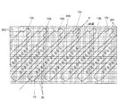
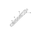
バンド形状の持層取出工程(ステップS1)は、用意された大判シートからバンド用の支持層を複数個取り出す工程である。図6には大判シートの一部が具体的に示されている。図6(A)は平面図、図6(B)はその部分拡大図である。また、図7には第2のバンド12の取出工程の様子が具体的に示されている。
(Band-shaped support layer removal process)
The band-shaped holding layer extraction step (step S1) is a step of extracting a plurality of band support layers from the prepared large sheet. FIG. 6 specifically shows a part of the large sheet. 6A is a plan view and FIG. 6B is a partially enlarged view thereof. FIG. 7 specifically shows the state of the
まず、図6(A)に示すように、大判シート200を用意する。大判シート200は、カーボン繊維束の伸長方向が互いに直交するカーボン繊維束の編物または織物である。この織物又は編み物は、図6(B)に示すように、カーボン繊維からなる繊維束を織り込み又は編み込んで形成されている。繊維束は、1本の直径が例えば7μmのカーボン繊維を例えば1000本(1K)束ねて形成されている。
なお、織物又は編み物の素材は、この実施の態様のようなカーボン繊維ではなく、ガラス繊維、アラミド繊維及びボロン繊維であっても良い。また、この織物又は編み物は、これらの繊維群の中から選んだ1種類又は2種類以上の繊維からなる繊維束を織り込み又は編み込んで形成しても良い。
大判シート200は個片のバンド用支持層を複数個取りできる大きさとなっている。ここで、支持層を複数個取りできるとは、本実施形態の場合、第1のバンド11または第2のバンド12のいずれか一方に用いられる個片の支持層を複数個取りできる場合と、第1のバンド11及び第2のバンド12の双方に用いられる個片の支持層を混在させて複数個取りできる場合とを含む。複数個取りとは多数個取りを含む概念である。
First, as shown in FIG. 6A, a
The material of the woven or knitted material may be glass fiber, aramid fiber, and boron fiber instead of the carbon fiber as in this embodiment. The woven fabric or knitted fabric may be formed by weaving or knitting a fiber bundle composed of one type or two or more types of fibers selected from these fiber groups.
The
大判シート200のカーボン繊維束の編物または織物には、上層の第1の樹脂層(第1の樹脂層11a,第1の樹脂層12a,第1の樹脂層18a)及び、下層の第2の樹脂層(第2の樹脂層11c,第2の樹脂層12c,第2の樹脂層18c)との材料との親和性を確保するために、前記上層及び前記下層の樹脂層と同系の樹脂を繊維束に含浸させてある。若しくは前記上層及び前記下層の樹脂層と同系の樹脂膜を当該大判シート200の表裏面のどちらか一面もしくは両面に圧着させてある。若しくは前記上層及び前記下層の樹脂層と同系の樹脂を繊維束に含浸させ、且つ、同系の樹脂膜を当該大判シート200の表裏面のどちらか一面もしくは両面に圧着させてある。
The knitted or woven fabric of the carbon fiber bundle of the
このような大判シート200から図7に示すように第2のバンド12の支持層12bをカットして多数個取りする。ここでは、大判シート200のカーボン繊維束の伸長方向(互いに直交する縦のカーボン繊維束201と横のカーボン繊維束202とのカーボン繊維束の伸長方向)に対して支持層の長手方向Hが予め定められている45度の傾斜角度となるようにカットして多数個取りしている。多数個取りは例えばプレスでの打ち抜きによって行う。バンド長さ調整穴20の打ち抜きは、この支持層12bの多数個取りと同時に、または異なった時点で、例えば、プレスによって行う。
As shown in FIG. 7, a large number of the support layers 12 b of the
図8には支持層取出工程で取り出された支持層12bの個片の一例が示されている。同様に、第1のバンド11の支持層11bや、遊環18の支持層18bの個片を多数個取りする。なお、可能であれば、支持層11b,12bを切り出した大判シート200に余裕があれば、そこから遊環用支持層18bをカットして取り出すことが好ましい。
FIG. 8 shows an example of individual pieces of the
(バンド形状の支持層変形工程)
次に、バンド形状の支持層変形工程について説明する。このバンド用の支持層変形工程は、図9及び図10に示すように、前述した支持層取出工程において大判シートから複数個取り出された支持層11b,12bに変形工程を施す工程である。この支持層11b,12bの変形工程にはループ形成工程が含まれる。また、支持層11b,12bには必要に応じて波形形成工程が施される。
(Band-shaped support layer deformation process)
Next, the band-shaped support layer deformation step will be described. As shown in FIGS. 9 and 10, the support layer deformation process for the band is a process in which a plurality of support layers 11 b and 12 b taken out from the large sheet in the support layer extraction process are subjected to the deformation process. The deformation process of the support layers 11b and 12b includes a loop formation process. The support layers 11b and 12b are subjected to a waveform forming process as necessary.
図9及び図10にはこのバンド用の支持層変形工程によって得られた第2のバンド12の支持層12bの具体例が示されている。ここで図9の支持層12bは波形形成後のものであり、図10の支持層12bは波形形成後にループ形成工程を施した支持層12bである。波形形成を行った部分Aが図9及び図10に示され、ループ形成を行った部分Bが図10に示されている。なお、ループ形成を行った後にはその形が崩れないようにバンド用支持層12bの重なり部分を圧接着しておくことが好ましい。
9 and 10 show specific examples of the
同様にして、第1のバンド11の支持層12bの波形形成及びループ形成を行う。ループ形成を行った後にはその形が崩れないように支持層12bの重なり部分を圧接着することが好ましい。また、遊環18用の支持層18bには遊環18の形とするためにループ形成を行う。ここでもループ形成を行った後にはその形が崩れないように支持層の重なり部分を圧接着することが好ましい。
Similarly, waveform formation and loop formation of the
(第1の樹脂成型工程及び第2の樹脂成型工程・・・インサート成型)
図11から図13は第2のバンド12の第1の樹脂成型工程及び第2の樹脂成型工程の具体例を示すが、この二つの工程のうち、第1の樹脂成型工程は、図11および図12に示すように、上型である固定側金型300と下型である可動側金型301とを用いて、この第2のバンド12を構成するための支持層12bの一面側に、当該支持層12bと同色系の第2の樹脂層12cを設ける工程である。
(First resin molding step and second resin molding step: insert molding)
FIGS. 11 to 13 show specific examples of the first resin molding step and the second resin molding step of the
また、第2の樹脂成型工程は、図12に示すように、下型である可動側金型301と別に用意した他の上型である固定側金型303とを用いて支持層12b,12bの他面側に透明系もしくは半透明系の樹脂層12aを設ける工程である。この第1の樹脂成型工程及び第2の樹脂成型工程の順序は逆であってもよい。
Further, as shown in FIG. 12, the second resin molding step is performed using support layers 12b and 12b using a
図11から図13は、この第2のバンド12の第1の樹脂成型工程及び第2の樹脂成型工程の具体例を示し、特に、バンド長さ調整穴20の部分の成型の仕方を示している。
11 to 13 show specific examples of the first resin molding process and the second resin molding process of the
次に、第1の樹脂成型工程を説明する。図11に示すように、上型である固定側金型300の凹部300a内にバンド用の支持層12bを設置し、支持層12bにおけるバンド長さ調整穴20に対応する位置に、バンド長さ調整穴20形成のため、可動側金型301側の突部301aと固定側金型300の突起300bとを互いに突き合わせて配置させる。そして、固定側金型300と可動側金型301とを型締めし、固定側金型300と可動側金型301とによって構成された多数のキャビティ302、302内に、溶融した熱可塑性樹脂、例えばポリウレタン樹脂を充填する。これによって支持層12bの下面に第2の樹脂層12cが設けられ、支持層12bは、固定側金型300から離れて第2の樹脂層12cに接着する。その後、第2の樹脂層12cを硬化させる。
Next, the first resin molding process will be described. As shown in FIG. 11, a
次に、第2の樹脂成型工程を説明する。図12に示すように、可動側金型301側に、第2の樹脂層12cが設けられた支持層12bを保持させたまま、可動側金型301を固定側金型300から引き離し、別の他の上型である固定側金型303に接合する。この固定側金型303は、支持層12bにおけるバンド長さ調整穴20に対応する穴に対応する位置に、可動側金型301側の突部301aと嵌合する突起303aを備えている。これら可動側金型301と別な他の固定側金型303とを型締めする。
Next, the second resin molding step will be described. As shown in FIG. 12, the
次に、固定側金型303と可動側金型301とによって構成された多数のキャビティ304内に、第1の樹脂層12aを形成するために溶融した熱可塑性樹脂、例えばポリウレタン樹脂を充填する。これによってバンド用支持層12bの上面に第1の樹脂層12aが設けられ、支持層12bは、この第1の樹脂層12aにも接着する。その後、第1の樹脂層12を硬化させる。この第1の成型工程及び第2の成型工程によって得られた第2のバンド12の一例が図13に示されている。同様にして、第1のバンド11及び遊環18の成型も行う。この場合、遊環18の成型に当たっては、金型内に、キャビティを画成する可動中子である中駒JIGが必要となる。この中駒JIGは、遊環18の成型のあとに当該遊環18から引き抜かれる。
Next, in a large number of
ところで、第1の成型工程及び第2の成型工程の際には、図14に示すように、樹脂の充填方向(X)は支持層12bの長手方向の一端側(図14中の左)から、長手方向の他端側(図14中の右)に向かう方向であるのが一般である。このとき、充填された樹脂は、固定側金型300の突起300bまたは固定側金型303の突起303aのうちの、樹脂が充填される始める突起300a、300bの前方外周面に当たって左右2つに分かれ、突起外周面に沿って流れ込んだあとに、突起300bまたは303aののうちの、樹脂が充填され終わる後方外周面で合流し、次の突起300bまたは303aの前方外周面に当たって左右2つに分かれ、突起外周面に沿って流れ込んだあとに、突起300bまたは303aの後方外周面で合流し、このようなことを繰り返すことになる。
By the way, in the first molding step and the second molding step, as shown in FIG. 14, the resin filling direction (X) is from one end side in the longitudinal direction of the
この場合、支持層12bの長手方向及び短手方向に対してカーボン繊維束の伸長方向が平行又は直交であって傾斜していないと、すなわち、支持層12bの長手方向及び短手方向がカーボン繊維束の伸長方向と同じ又は直交していると、溶融樹脂が回り込んだ後に再び合流して発生するウエルドライン(樹脂の流れ道。樹脂強度が弱い部分)と、前記カーボン繊維束の伸長方向の、隣り合う繊維束と繊維束との織目の隙間(繊維が無い空隙部分)が直線状に重なることがある。この結果、支持層12bにおいて、隣接のバンド長さ調整穴20の間を結ぶ線上に、非常に強度が弱く、バンドの使用中に切れやすい、いわゆる筋(すじ)が形成されてしまう。
In this case, if the elongation direction of the carbon fiber bundle is parallel or orthogonal to the longitudinal direction and the short direction of the
しかし、支持層12bの長手方向及び短手方向に対してカーボン繊維束の伸長方向が予め定められている傾斜角度(例えば、45度)で傾斜しているので、溶融樹脂が回り込んだ後に再び合流して発生するウエルドライン(樹脂の流れ道。樹脂強度が弱い部分)ができても、当該ウエルドライン下には、強度の強い繊維束が必ず存在するため、このようないわゆる筋が形成されないために、バンド長さ調整穴20の部分から支持層12bの長手方向に沿って、バンド使用中における、いわゆる切れが発生することを未然に防止することができる。
However, since the elongation direction of the carbon fiber bundle is inclined at a predetermined inclination angle (for example, 45 degrees) with respect to the longitudinal direction and the short direction of the
この実施の形態に係るバンドの製造方法によれば、カーボン繊維束の伸長方向が互いに直交するように編まれたカーボン繊維束で構成された大判シートを用意し、この用意された大判シートから、当該大判シートのカーボン繊維束の伸長方向に対して予め定められている傾斜角度で傾斜するように複数個のバンド用の支持層をカットして同時に取り出すことができる。このために、カーボン繊維束の伸長方向が予め定められている傾斜角度で傾斜する複数個の支持層を迅速かつ容易に製造することができる。 According to the method of manufacturing a band according to this embodiment, a large sheet composed of carbon fiber bundles knitted so that the extending directions of the carbon fiber bundles are orthogonal to each other is prepared, and from the prepared large sheet, The support layers for a plurality of bands can be cut and taken out simultaneously so as to be inclined at a predetermined inclination angle with respect to the extending direction of the carbon fiber bundle of the large sheet. For this reason, a plurality of support layers in which the extending direction of the carbon fiber bundle is inclined at a predetermined inclination angle can be manufactured quickly and easily.
この実施の形態に係るバンドの製造方法によれば、そればかりでなく、その後、金型を用いて支持層の一面側に第1の樹脂層を密着して設ける一方で、金型を用いて支持層の他面側に第2の樹脂層を密着して設けることができる。このために、美的な外観形状をし、かつ、高級感のあるバンドを製造することができる。 According to the method of manufacturing a band according to this embodiment, not only that, but after that, using the mold, the first resin layer is provided in close contact with the one surface side of the support layer. The second resin layer can be provided in close contact with the other surface side of the support layer. For this reason, it is possible to manufacture a high-quality band having an aesthetic appearance.
以上のように、この実施の形態に係るバンドは、長手方向に複数のバンド長さ調整穴(図1のバンド長さ調整穴20)が形成されたバンド本体(図1のバンド本体10)を備えているバンドにおいて、前記バンド本体は、カーボン繊維束の織物または編み物からなる支持層(図2の支持層11b,図4の支持層12b)と、この支持層の表面に密着して設けられた第1の樹脂層(図2の第1の樹脂層11a,図4の第1の樹脂層12a)と、前記支持層の裏面に密着して設けられた第2の樹脂層(図2の第2の樹脂層11c,図4の第2の樹脂層12c)とを備え、前記支持層は、前記バンド本体の長手方向及び短手方向に対してカーボン繊維束の伸長方向が予め定められた傾斜角度で傾斜するよう形成されている(図7)ことを特徴とする。
この実施の形態に係るバンドは、前記予め定められた傾斜角度は、前記バンドの長手方向及び短手方向に対してカーボン繊維束の伸長方向が15度から75度、または45度の傾斜角度であることを特徴とする。
As described above, the band according to this embodiment includes a band body (
In the band according to this embodiment, the predetermined inclination angle is such that the extension direction of the carbon fiber bundle is 15 to 75 degrees or 45 degrees with respect to the longitudinal direction and the short direction of the band. It is characterized by being.
この実施の形態に係るバンドで、前記支持層は、ばね棒穴(図1のばね棒穴13a,15a,19a)を有し、当該ばね棒穴に対応する部分に当該ばね棒穴を取り囲むループが形成され、かつ、当該バンド本体の最外形よりも一回り小さく形成されており、前記支持層の表面には透明系もしくは半透明系の第1の樹脂層(図2の第1の樹脂層11a,図4の第1の樹脂層12a)が密着して設けられ、前記支持層の裏面には当該支持層と同色系の第2の樹脂層(図2の第2の樹脂層11c,図4の第2の樹脂層12c)が設けられ、前記第1の樹脂層と前記第2の樹脂層によって前記バンド本体の最外形が形成されていることを特徴とする。
In the band according to this embodiment, the support layer has a spring bar hole (
この実施の形態に係る腕時計は、バンド本体と、このバンド本体に設けられた時計本体ケースとを備えており、前記バンド本体は、カーボン繊維束の織物又は編み物からなる支持層(図2の支持層11b,図4の支持層12b)と、この支持層の表面に密着して設けられた第1の樹脂層(図2の第1の樹脂層11a,図4の第1の樹脂層12a)と、前記支持層の裏面に密着して設けられた第2の樹脂層(図2の第2の樹脂層11c,図4の第2の樹脂層12c)とを備え、前記支持層は、前記バンド本体の長手方向及び短手方向に対してカーボン繊維束の伸長方向が予め定められた傾斜角度で傾斜するよう形成されている(図7)ことを特徴とする。
The wristwatch according to this embodiment includes a band main body and a watch main body case provided on the band main body, and the band main body includes a support layer made of a woven or knitted carbon fiber bundle (the support in FIG. 2).
この実施の形態に係るバンドの製造方法は、カーボン繊維束の伸長方向が互いに直交するように編まれた大判シート(図6の大判シート200)を用意し、この用意された大判シートから、当該大判シートのカーボン繊維束の伸長方向に対して予め定められている傾斜角度で傾斜するように複数個のバンド用支持層(図7の支持層12b)をカットして取り出す支持層取出工程(図5のステップS1;図6,図7、図8)と、金型を用いて前記支持層の一面側に第1の樹脂層を密着して設けるための第1の成型工程(図5のステップS3;図11)と、金型を用いて前記支持層の他面側に第2の樹脂層を密着して設けるための第2の成型工程(図5のステップS4;図12)とを備えたことを特徴とする。
The method for manufacturing a band according to this embodiment prepares a large sheet (
この実施の形態に係るバンドの製造方法で、前記支持層取出工程は、前記大判シートのカーボン繊維束の伸長方向に対して、前記支持層の伸長方向が予め定められている傾斜角度として45度傾斜するように当該大判シートから当該支持層をカットして取り出す工程を含むことを特徴とする。
また、この実施の形態に係るバンドの製造方法で、前記大判シートは、(1)前記カーボン繊維束に前記第1の樹脂層及び第2の樹脂層と同じ樹脂を含浸させておく、(2)若しくは同じ樹脂系の樹脂膜を当該大判シートの表裏面のどちらか一面もしくは両面に圧着させておく、(3)若しくは前記第1及び第2の樹脂層と同じ樹脂を含浸させ、且つ、同じ樹脂系の樹脂膜を当該大判シートの表裏面のどちらか一面または両面に圧着させておくことを特徴とする。
In the band manufacturing method according to this embodiment, the support layer take-out step is 45 degrees as an inclination angle in which the extension direction of the support layer is predetermined with respect to the extension direction of the carbon fiber bundle of the large sheet. It includes a step of cutting and taking out the support layer from the large sheet so as to be inclined.
Further, in the band manufacturing method according to this embodiment, the large sheet (1) impregnates the carbon fiber bundle with the same resin as the first resin layer and the second resin layer. ) Or the same resin-based resin film is bonded to either one or both of the front and back surfaces of the large sheet. (3) Or impregnated with the same resin as the first and second resin layers, and the same A resin-based resin film is bonded to either one or both of the front and back surfaces of the large sheet.
なお、この実施の態様の場合、大判シート200は、矩形の形をしており、そのカーボン繊維束の伸長方向は、その矩形の縦横の辺に平行である。即ち、縦横のカーボン繊維束は、直交している。そして、大判シート200のカーボン繊維束の伸長方向に対して支持層の伸長方向が45度の傾斜角度となるように支持層をカットして多数個取り出している。
In this embodiment, the
これに対して、大判シート200が矩形状であって、その直交するカーボン繊維束の伸長方向が矩形状の大判シート200の縦辺又は横辺に対して45度で交差する場合、その矩形の縦辺または横辺に対して支持層の伸長方向が平行となるように支持層をカットして多数個取り出してもよい。
On the other hand, when the
また、この実施の態様の場合、支持層の長手方向がカーボン繊維束の伸長方向に対して45度の傾斜角度となるように形成しているが、43度、30度など、他の傾斜角度で形成されていてもよい。好ましくは、15度から75度の傾斜角度が望ましい。
15度より小さい傾斜角度及び75度より大きい傾斜角度の場合、バンド本体を長手方向に伸ばす力に対して、第1及び第2の各樹脂層は伸びに追従するものの、カーボン繊維束がバンドの伸びに追従しないため、前記各樹脂層とカーボン繊維束からなる当該支持層との間に剥離が起きてしまう。よって、長手方向の引っ張りや捩れに対してバンドの強度を大幅に向上させることができない。また、15度より小さい傾斜角度及び75度より大きい傾斜角度の場合、溶融樹脂が回り込んだ後に再び合流して発生するウエルドライン(樹脂の流れ道。樹脂強度が弱い部分)と、前記カーボン繊維束の伸長方向の、隣り合う繊維束と繊維束との織目の隙間(繊維が無い空隙部分)が直線状に重なることがある。この結果、支持層12bにおいて、隣接のバンド長さ調整穴20の間を結ぶ線上に、非常に強度が弱く、バンドの使用中に切れやすい、いわゆる筋(すじ)が形成されてしまう。
In the case of this embodiment, the support layer is formed so that the longitudinal direction of the support layer has an inclination angle of 45 degrees with respect to the extending direction of the carbon fiber bundle. However, other inclination angles such as 43 degrees and 30 degrees are used. May be formed. An inclination angle of 15 to 75 degrees is desirable.
In the case of an inclination angle smaller than 15 degrees and an inclination angle larger than 75 degrees, the first and second resin layers follow the elongation with respect to the force of extending the band body in the longitudinal direction, but the carbon fiber bundles are Since it does not follow the elongation, peeling occurs between the resin layers and the support layer made of the carbon fiber bundle. Therefore, the strength of the band cannot be significantly improved against the pulling or twisting in the longitudinal direction. In addition, in the case of an inclination angle smaller than 15 degrees and an inclination angle larger than 75 degrees, a weld line (resin flow path, a portion where the resin strength is weak) generated by joining again after the molten resin wraps around, and the carbon fiber There is a case where a gap between adjacent fiber bundles and fiber bundles in the extending direction of the bundle (a void portion without fibers) overlaps linearly. As a result, in the
また、この実施の態様の場合、支持層の構成素材として、カーボン繊維束の織物または編み物を用いているが、これに限定されず、例えば、ガラス繊維、アラミド繊維、及びボロン繊維の繊維群から選んだ1種類または2種類以上の繊維束を当該繊維束の伸長方向が互いに直交するように織り込み又は編み込んで形成された織物又は編み物の表面に、アルミ合金やニッケル合金等の金属粒子を蒸着、スパッタリングさせて、表面に金属を付着させた織物又は編み物を用いるようにしてもよい。
さらに、この実施の態様の場合、この発明を時計用のバンドに適用した場合について説明しているが、これに限定されず、洋装用のベルト、腕バンドなどの各種のバンドに適用可能である。
Further, in the case of this embodiment, as a constituent material of the support layer, a woven or knitted carbon fiber bundle is used, but is not limited thereto. For example, from a fiber group of glass fiber, aramid fiber, and boron fiber Metal particles such as aluminum alloy and nickel alloy are vapor-deposited on the surface of a woven or knitted fabric formed by weaving or braiding the selected one or two or more types of fiber bundles so that the extension directions of the fiber bundles are orthogonal to each other. You may make it use the textile fabric or knitting which sputter | sputtered and made the metal adhere to the surface.
Further, in the case of this embodiment, the case where the present invention is applied to a watch band is described, but the present invention is not limited to this, and can be applied to various bands such as a belt for armor and an arm band. .
種々の変形例は、本発明の広範な趣旨及び範囲から逸脱せずになし得よう。
上記実施の形態及び変形例は、本発明の例示を意図するものであり、本発明の制限を意図するものではない。本発明の範囲は、上記の実施例及び変形例よりもむしろ添付の請求項によりしめされ、本発明の請求項の範囲及びその均等物の意味範囲でなされた種々の変更は本発明の範囲に入るものとみなされるべきである。
Various modifications may be made without departing from the broad spirit and scope of the invention.
The above embodiments and modifications are intended to illustrate the present invention and are not intended to limit the present invention. The scope of the present invention is defined by the appended claims rather than the embodiments and modifications described above, and various modifications made within the scope of the claims of the present invention and the equivalents thereof are within the scope of the present invention. Should be considered as entering.
100 腕時計
1 本体ケース
2,3 バンド取付部
10 時計用バンド
11 第1のバンド
11a 第1の樹脂層
11b バンド用カーボンシート
11c 第2の樹脂層
12 第2のバンド
12a 第1の樹脂層
12b バンド用カーボンシート
12c 第2の樹脂層
13a,15a,19a ばね棒穴
18 遊環
100
Claims (16)
前記バンド本体は、
カーボン繊維、ガラス繊維、アラミド繊維及びボロン繊維の繊維群の中から選んだ1種類又は2種類以上の繊維からなる繊維束を織り込み又は編み込んで形成された織物又は編み物からなるバンド形状の支持層と、
この支持層の表面に密着して設けられ、前記バンド本体の表面を構成する第1の樹脂層と、
前記支持層の裏面に密着して設けられ、前記バンド本体の裏面を構成する第2の樹脂層とを備え、
前記支持層は、前記バンド本体の長手方向及び短手方向に対してその繊維束の伸長方向が予め定められた傾斜角度で形成され、前記第1の樹脂層と前記第2の樹脂層とともにバンド本体の長手方向の伸びに追従することを特徴とするバンド。 In the band having a band body in which a plurality of band length adjustment holes are formed in the longitudinal direction,
The band body is
A band-shaped support layer made of a woven or knitted fabric formed by weaving or knitting a fiber bundle made of one or more kinds of fibers selected from the group of carbon fiber, glass fiber, aramid fiber and boron fiber; ,
A first resin layer provided in close contact with the surface of the support layer and constituting the surface of the band body ;
A second resin layer provided in close contact with the back surface of the support layer and constituting the back surface of the band body ;
The support layer is formed with an inclination angle in which the extension direction of the fiber bundle is predetermined with respect to the longitudinal direction and the short direction of the band main body, and the band together with the first resin layer and the second resin layer. A band characterized by following the longitudinal elongation of the body.
前記バンド本体は、
カーボン繊維、ガラス繊維、アラミド繊維及びボロン繊維の繊維群の中から選んだ1種類又は2種類以上の繊維からなる繊維束を織り込み又は編み込んで形成された織物又は編み物の繊維層と、この繊維層の表面に形成されたアルミ合金、ニッケル合金等の金属粒子からなる金属層とからなるバンド形状の支持層と、
この支持層の表面に密着して設けられ、前記バンド本体の表面を構成する第1の樹脂層と、
前記支持層の裏面に密着して設けられ、前記バンド本体の裏面を構成する第2の樹脂層とを備え、
前記支持層は、前記バンド本体の長手方向及び短手方向に対してその繊維束の伸長方向が予め定められた傾斜角度で形成され、前記第1の樹脂層と前記第2の樹脂層とともにバンド本体の長手方向の伸びに追従することを特徴とするバンド。 In the band having a band body in which a plurality of band length adjustment holes are formed in the longitudinal direction,
The band body is
A woven or knitted fiber layer formed by weaving or knitting a fiber bundle made of one or two or more kinds of fibers selected from the group of carbon fibers, glass fibers, aramid fibers and boron fibers, and this fiber layer A band-shaped support layer comprising a metal layer made of metal particles such as an aluminum alloy and a nickel alloy formed on the surface of
A first resin layer provided in close contact with the surface of the support layer and constituting the surface of the band body ;
A second resin layer provided in close contact with the back surface of the support layer and constituting the back surface of the band body ;
The support layer is formed with an inclination angle in which the extension direction of the fiber bundle is predetermined with respect to the longitudinal direction and the short direction of the band main body, and the band together with the first resin layer and the second resin layer. A band characterized by following the longitudinal elongation of the body.
前記バンド本体は、
支持層と、
この支持層の表面に密着して設けられ、前記バンド本体の表面を構成する第1の樹脂層と、
前記支持層の裏面に密着して設けられ、前記バンド本体の裏面を構成する第2の樹脂層とを備え、
前記支持層は、
カーボン繊維、ガラス繊維、アラミド繊維及びボロン繊維の繊維群の中から選んだ1種類又は2種類以上の繊維からなる繊維束を織り込み又は編み込んで形成された織物又は編み物に、前記第1の樹脂層及び第2の樹脂層と同系の樹脂を含浸させ、及び前記第1の樹脂層及び第2の樹脂層と同系の樹脂から成る樹脂膜を圧着させて形成され、
前記支持層の織物又は編み物が、前記バンド本体の長手方向及び短手方向に対してその繊維束の伸長方向が予め定められた傾斜角度で形成され、前記第1の樹脂層と前記第2の樹脂層とともにバンド本体の長手方向の伸びに追従することを特徴とするバンド。 In the band having a band body in which a plurality of band length adjustment holes are formed in the longitudinal direction,
The band body is
A support layer;
A first resin layer provided in close contact with the surface of the support layer and constituting the surface of the band body ;
A second resin layer provided in close contact with the back surface of the support layer and constituting the back surface of the band body ;
The support layer is
The first resin layer is formed on a woven fabric or a knitted fabric formed by weaving or braiding a fiber bundle composed of one or two or more kinds of fibers selected from a group of carbon fibers, glass fibers, aramid fibers, and boron fibers. and a second resin layer and the same type of resin impregnated, is formed by crimping the resin film made及beauty before Symbol first resin layer and second resin layer and the same type of the resin,
Woven or knitted of said support layer, wherein the band body longitudinal direction and the extending direction of the fiber bundle with respect to lateral direction is formed at an inclined angle predetermined, and the first resin layer and the second A band characterized by following the longitudinal extension of the band body together with the resin layer.
このバンドに設けられた本体ケースと、
を備えていることを特徴とする腕時計。 The band according to any one of claims 1 to 8,
A body case provided on this band,
A wristwatch characterized by comprising:
金型を用いて前記大判シートから取り出された複数個の各支持層の一面側にバンド本体の一面を構成する第1の樹脂層を密着して設けるステップと、
金型を用いて前記複数個の各支持層の他面側にバンド本体の他面を構成する第2の樹脂層を密着して設けるステップとを備え、
前記第1の樹脂層と前記第2の樹脂層は、前記支持層とともにバンド本体の長手方向の伸びに追従する材料とすることを特徴とするバンドの製造方法。 It is formed by weaving or weaving a fiber bundle composed of one or two or more kinds of fibers selected from the group of carbon fibers, glass fibers, aramid fibers and boron fibers so that the extension directions of the fiber bundles are orthogonal to each other. A plurality of band-shaped support layers are cut out from a large sheet provided with a support layer made of woven or knitted fabric at a predetermined inclination angle with respect to the extending direction of the fiber bundle of the large sheet. Steps,
A step of closely adhering a first resin layer constituting one surface of the band main body to one surface side of each of the plurality of support layers taken out from the large sheet using a mold;
Providing a second resin layer constituting the other surface of the band body in close contact with the other surface side of each of the plurality of support layers using a mold,
The method of manufacturing a band, wherein the first resin layer and the second resin layer are made of a material that follows the longitudinal extension of the band body together with the support layer.
金型を用いて前記大判シートから取り出された複数個の各支持層の一面側に、バンド本体の一面を構成する第1の樹脂層を密着して設けるステップと、
金型を用いて前記複数個の各支持層の他面側に、バンド本体の他面を構成する第2の樹脂層を密着して設けるステップとを備え、
前記第1の樹脂層と前記第2の樹脂層は、前記支持層とともにバンド本体の長手方向の伸びに追従する材料とすることを特徴とするバンドの製造方法。 It is formed by weaving or weaving a fiber bundle composed of one or two or more kinds of fibers selected from the group of carbon fibers, glass fibers, aramid fibers and boron fibers so that the extension directions of the fiber bundles are orthogonal to each other. From a large sheet having a support layer composed of a fiber layer of a woven or knitted fabric and a metal layer made of metal particles such as an aluminum alloy or a nickel alloy formed on the surface of the fiber layer, a fiber bundle of the large sheet Cutting and removing a plurality of band-shaped support layers at a predetermined inclination angle with respect to the extending direction of
A step of providing a first resin layer constituting one surface of the band body in close contact with one surface side of each of the plurality of support layers taken out from the large sheet using a mold;
A second resin layer that constitutes the other surface of the band body is provided in close contact with the other surface side of each of the plurality of support layers using a mold, and
The method of manufacturing a band, wherein the first resin layer and the second resin layer are made of a material that follows the longitudinal extension of the band body together with the support layer.
金型を用いて前記大判シートから取り出された複数個の各支持層の一面側に、バンド本体の一面を構成する第1の樹脂層を密着して設けるステップと、
金型を用いて前記複数個の各支持層の他面側に、バンド本体の他面を構成する第2の樹脂層を密着して設けるステップとを備え、
前記第1の樹脂層と前記第2の樹脂層は、前記支持層とともにバンド本体の長手方向の伸びに追従する材料とすることを特徴とするバンドの製造方法。 It is formed by weaving or weaving a fiber bundle composed of one or two or more kinds of fibers selected from the group of carbon fibers, glass fibers, aramid fibers and boron fibers so that the extension directions of the fiber bundles are orthogonal to each other. and a fibrous layer of woven or knitted impregnated with the first resin layer and second resin layer and the same type of the resin, the resin consisting及beauty before Symbol first resin layer and second resin layer and the same type of resin A plurality of band-shaped support layers are cut from a large sheet having a support layer formed by pressure-bonding a membrane at a predetermined inclination angle with respect to the direction of elongation of the fiber bundle of the large sheet. Step to take out,
A step of providing a first resin layer constituting one surface of the band body in close contact with one surface side of each of the plurality of support layers taken out from the large sheet using a mold;
A second resin layer that constitutes the other surface of the band body is provided in close contact with the other surface side of each of the plurality of support layers using a mold, and
The method of manufacturing a band, wherein the first resin layer and the second resin layer are made of a material that follows the longitudinal extension of the band body together with the support layer.
Priority Applications (4)
| Application Number | Priority Date | Filing Date | Title |
|---|---|---|---|
| JP2010181370A JP5153837B2 (en) | 2009-09-01 | 2010-08-13 | BAND, WATCH AND BAND MANUFACTURING METHOD |
| CN201610160759.5A CN105768409B (en) | 2009-09-01 | 2010-09-01 | The manufacturing method of band, wrist-watch and band |
| CN201010270819.1A CN101999782B (en) | 2009-09-01 | 2010-09-01 | The manufacture method of band, wrist-watch and band |
| US12/873,590 US8613544B2 (en) | 2009-09-01 | 2010-09-01 | Band, wristwatch with the band and method of making the band |
Applications Claiming Priority (3)
| Application Number | Priority Date | Filing Date | Title |
|---|---|---|---|
| JP2009201439 | 2009-09-01 | ||
| JP2009201439 | 2009-09-01 | ||
| JP2010181370A JP5153837B2 (en) | 2009-09-01 | 2010-08-13 | BAND, WATCH AND BAND MANUFACTURING METHOD |
Related Child Applications (1)
| Application Number | Title | Priority Date | Filing Date |
|---|---|---|---|
| JP2012093661A Division JP5726803B2 (en) | 2009-09-01 | 2012-04-17 | BAND, WATCH AND BAND MANUFACTURING METHOD |
Publications (2)
| Publication Number | Publication Date |
|---|---|
| JP2011072777A JP2011072777A (en) | 2011-04-14 |
| JP5153837B2 true JP5153837B2 (en) | 2013-02-27 |
Family
ID=43624739
Family Applications (1)
| Application Number | Title | Priority Date | Filing Date |
|---|---|---|---|
| JP2010181370A Active JP5153837B2 (en) | 2009-09-01 | 2010-08-13 | BAND, WATCH AND BAND MANUFACTURING METHOD |
Country Status (3)
| Country | Link |
|---|---|
| US (1) | US8613544B2 (en) |
| JP (1) | JP5153837B2 (en) |
| CN (2) | CN101999782B (en) |
Families Citing this family (39)
| Publication number | Priority date | Publication date | Assignee | Title |
|---|---|---|---|---|
| CN102742983B (en) * | 2012-07-19 | 2016-01-06 | 力其国际有限公司 | The preparation method of rubber layer mold stampings |
| JP5447900B1 (en) * | 2012-08-30 | 2014-03-19 | カシオ計算機株式会社 | Guidelines |
| EP2742821B1 (en) * | 2012-12-17 | 2015-09-09 | The Swatch Group Research and Development Ltd. | Method for manufacturing a flexible portable electronic device |
| JP5800205B2 (en) * | 2013-02-22 | 2015-10-28 | カシオ計算機株式会社 | Member connection structure, band mounting structure, and watch |
| JP2014236781A (en) * | 2013-06-06 | 2014-12-18 | カシオ計算機株式会社 | Member connecting structure, band attachment structure, and watch |
| WO2015065460A1 (en) * | 2013-10-31 | 2015-05-07 | Bodhi Technology Ventures Llc | Flexibility-controlled composite material and method of manufacture |
| KR102201921B1 (en) * | 2014-04-11 | 2021-01-12 | 삼성전자주식회사 | Wearable electronic device with buckle |
| US20160004222A1 (en) * | 2014-07-03 | 2016-01-07 | Everest Horology Products | End links for use in coupling watch straps to bases of watches, and related methods |
| USD759725S1 (en) | 2014-09-08 | 2016-06-21 | Apple Inc. | Wearable device |
| USD771036S1 (en) | 2014-08-11 | 2016-11-08 | Apple Inc. | Wearable device |
| USD727198S1 (en) | 2014-08-11 | 2015-04-21 | Apple Inc. | Band |
| USD755299S1 (en) | 2014-09-05 | 2016-05-03 | Apple Inc. | Label |
| KR102329820B1 (en) * | 2015-01-29 | 2021-11-23 | 삼성전자주식회사 | Wearable type device |
| JP6537014B2 (en) * | 2015-03-17 | 2019-07-03 | カシオ計算機株式会社 | Pointer and watch |
| CN105058667A (en) * | 2015-07-20 | 2015-11-18 | 东莞劲胜精密组件股份有限公司 | Manufacturing method and device for double-color bracelet |
| JP6284042B2 (en) * | 2015-12-10 | 2018-02-28 | カシオ計算機株式会社 | Band and watch |
| EP3189954A1 (en) * | 2016-01-07 | 2017-07-12 | The Swatch Group Research and Development Ltd. | Bracelet and method for manufacturing thereof |
| USD795121S1 (en) | 2016-03-07 | 2017-08-22 | Apple Inc. | Band |
| USD777163S1 (en) | 2016-03-07 | 2017-01-24 | Apple Inc. | Wearable device |
| USD781853S1 (en) | 2016-03-07 | 2017-03-21 | Apple Inc. | Wearable device |
| USD789822S1 (en) | 2016-03-07 | 2017-06-20 | Apple Inc. | Band |
| CN106174921A (en) * | 2016-07-25 | 2016-12-07 | 歌尔股份有限公司 | Wrist strap |
| CN106579666A (en) * | 2016-12-15 | 2017-04-26 | 杭州盈网科技有限公司 | Unstretchable silica gel conductive wrist band |
| KR101742766B1 (en) | 2017-01-17 | 2017-06-15 | 주식회사 지아이에스21 | Process for producing paper band for wrist watch and the paper band for wrist watch produced therefrom |
| USD838619S1 (en) | 2017-03-10 | 2019-01-22 | Apple Inc. | Band |
| KR102023636B1 (en) * | 2017-11-06 | 2019-09-20 | 주식회사 부일신소재 | Parts of wrist watch using carbon composite and method for manufacturing the same |
| JP6971864B2 (en) * | 2018-01-15 | 2021-11-24 | オムロン株式会社 | How to make a belt |
| USD853267S1 (en) * | 2018-02-20 | 2019-07-09 | Christopher A. Glover | Watch band adapter |
| AU2019227071A1 (en) * | 2018-03-02 | 2020-09-24 | Nitto Denko Corporation | Wearable physiological device and apparatus |
| JP6825597B2 (en) * | 2018-03-14 | 2021-02-03 | カシオ計算機株式会社 | Molded product manufacturing method and band manufacturing method |
| JP2019154901A (en) * | 2018-03-15 | 2019-09-19 | カシオ計算機株式会社 | Watchband and watch |
| JP7324437B2 (en) * | 2018-03-15 | 2023-08-10 | カシオ計算機株式会社 | band and watch |
| JP2019162202A (en) * | 2018-03-19 | 2019-09-26 | セイコーエプソン株式会社 | Resin member and wearable band |
| CN112584723A (en) * | 2018-03-26 | 2021-03-30 | 歌沃福风险投资公司 | Exhaust ring and method for manufacturing the same |
| JP7440841B2 (en) * | 2018-05-15 | 2024-02-29 | 積水ポリマテック株式会社 | Rubber band manufacturing method, rubber bands and electronic devices worn on the human body |
| JP6913306B2 (en) * | 2019-04-01 | 2021-08-04 | カシオ計算機株式会社 | Exterior parts, cases and watches |
| US11241068B2 (en) | 2019-04-15 | 2022-02-08 | Apple Inc. | Watch band with braided strands |
| CN110103382B (en) * | 2019-05-10 | 2021-11-12 | 广东乐心医疗电子股份有限公司 | Multicolor fluororubber belt body, preparation method thereof and wearable equipment |
| USD936166S1 (en) * | 2020-07-24 | 2021-11-16 | Eric Ehmer | Interlocking elongate flotation device |
Family Cites Families (17)
| Publication number | Priority date | Publication date | Assignee | Title |
|---|---|---|---|---|
| US3362595A (en) * | 1966-02-09 | 1968-01-09 | Bauer Gustav | Watchband |
| US3578208A (en) * | 1969-02-18 | 1971-05-11 | Bauer Gustav Fa | Watch band strap with releasable end connection |
| JPS58114109U (en) | 1982-01-29 | 1983-08-04 | シチズン時計株式会社 | watch band |
| JPS59108410U (en) * | 1983-01-12 | 1984-07-21 | 株式会社和久元 | watch band |
| JPS6260511A (en) * | 1985-09-10 | 1987-03-17 | シチズン時計株式会社 | Composite band for clock |
| JP3194149B2 (en) * | 1991-05-15 | 2001-07-30 | カシオ計算機株式会社 | Resin band and method of manufacturing resin band |
| JPH0796808A (en) * | 1993-09-28 | 1995-04-11 | Achilles Corp | Manufacture of vehicle air bag and vehicle air bag |
| JPH07136008A (en) * | 1993-11-18 | 1995-05-30 | Seiko Instr Inc | Band for wrist watch |
| JP2835933B2 (en) * | 1995-01-12 | 1998-12-14 | セイコー株式会社 | Wristwatch leather band and method of manufacturing the same |
| DE29801546U1 (en) * | 1998-02-02 | 1998-04-09 | Vedag Dachsysteme Gmbh & Co Kg | Vapor barrier |
| JP2000160475A (en) * | 1998-11-26 | 2000-06-13 | Falcon Technology:Kk | Cloth and clothes |
| JP2001024343A (en) * | 1999-07-13 | 2001-01-26 | Casio Comput Co Ltd | Two-color molded object and watch band |
| US7275667B2 (en) * | 2003-06-04 | 2007-10-02 | Bertucci Michael H | Watch band construction |
| US20070200042A1 (en) * | 2003-12-06 | 2007-08-30 | Christian Gschwend | Bag Holder |
| JP2005177007A (en) | 2003-12-17 | 2005-07-07 | Mitsubishi Materials Corp | Belt attachment |
| JP2006271610A (en) | 2005-03-29 | 2006-10-12 | Casio Comput Co Ltd | Band |
| WO2009059209A2 (en) * | 2007-10-31 | 2009-05-07 | Movado Llc | Integrated watchband and methods therefor |
-
2010
- 2010-08-13 JP JP2010181370A patent/JP5153837B2/en active Active
- 2010-09-01 US US12/873,590 patent/US8613544B2/en active Active
- 2010-09-01 CN CN201010270819.1A patent/CN101999782B/en active Active
- 2010-09-01 CN CN201610160759.5A patent/CN105768409B/en active Active
Also Published As
| Publication number | Publication date |
|---|---|
| JP2011072777A (en) | 2011-04-14 |
| CN101999782A (en) | 2011-04-06 |
| CN105768409A (en) | 2016-07-20 |
| US20110051569A1 (en) | 2011-03-03 |
| CN101999782B (en) | 2016-03-30 |
| US8613544B2 (en) | 2013-12-24 |
| CN105768409B (en) | 2018-07-06 |
Similar Documents
| Publication | Publication Date | Title |
|---|---|---|
| JP5153837B2 (en) | BAND, WATCH AND BAND MANUFACTURING METHOD | |
| JP5726803B2 (en) | BAND, WATCH AND BAND MANUFACTURING METHOD | |
| JP4836413B2 (en) | Bicycle component and manufacturing method thereof | |
| US20020106952A1 (en) | Resin injection molded article with reinforcing or decorative core | |
| CA2763280A1 (en) | Method for bonding plastic mold member onto metal housing | |
| JP2008021568A (en) | Keytop and its manufacturing method | |
| US9448419B2 (en) | Process of manufacturing of coated spectacle frames, and coated spectacle frames so obtained | |
| JP5334305B2 (en) | Manufacturing method of fishing line guide | |
| JP5334306B2 (en) | Fishing line guide | |
| JP7159691B2 (en) | Band manufacturing method, band and watch | |
| US20140283974A1 (en) | Method for manufacturing a structural part made of a composite material and including a radially oriented double yoke | |
| CN102653139A (en) | Method for producing a fibre reinforced plastic component | |
| JP5514061B2 (en) | Fishing line guide and manufacturing method thereof | |
| KR102085253B1 (en) | Manufacturing method for 3D cover structure | |
| JPH07136008A (en) | Band for wrist watch | |
| US20150327641A1 (en) | Composite fiber reinforcement for stiffening shells | |
| EP1035243A1 (en) | Toothed wheel, particularly for weaving looms and the like | |
| KR101407930B1 (en) | Manufacturing process of spectacles frame using carbon fiber | |
| CN102848678B (en) | A fiber composite material and its manufacturing method | |
| JP3197117U (en) | Carbon fiber wheel | |
| JP5308367B2 (en) | Fishing line guide | |
| JP2019158817A (en) | Watch dial and watch | |
| JP5546608B2 (en) | Fishing line guide | |
| JP5546609B2 (en) | Fishing line guide | |
| KR102617114B1 (en) | Polyurethane logo label manufacturing method |
Legal Events
| Date | Code | Title | Description |
|---|---|---|---|
| A977 | Report on retrieval |
Free format text: JAPANESE INTERMEDIATE CODE: A971007 Effective date: 20110922 |
|
| A131 | Notification of reasons for refusal |
Free format text: JAPANESE INTERMEDIATE CODE: A131 Effective date: 20111011 |
|
| A521 | Request for written amendment filed |
Free format text: JAPANESE INTERMEDIATE CODE: A523 Effective date: 20111212 |
|
| A02 | Decision of refusal |
Free format text: JAPANESE INTERMEDIATE CODE: A02 Effective date: 20120117 |
|
| A521 | Request for written amendment filed |
Free format text: JAPANESE INTERMEDIATE CODE: A523 Effective date: 20120417 |
|
| A911 | Transfer to examiner for re-examination before appeal (zenchi) |
Free format text: JAPANESE INTERMEDIATE CODE: A911 Effective date: 20120425 |
|
| A912 | Re-examination (zenchi) completed and case transferred to appeal board |
Free format text: JAPANESE INTERMEDIATE CODE: A912 Effective date: 20120615 |
|
| A61 | First payment of annual fees (during grant procedure) |
Free format text: JAPANESE INTERMEDIATE CODE: A61 Effective date: 20121204 |
|
| FPAY | Renewal fee payment (event date is renewal date of database) |
Free format text: PAYMENT UNTIL: 20151214 Year of fee payment: 3 |
|
| R150 | Certificate of patent or registration of utility model |
Ref document number: 5153837 Country of ref document: JP Free format text: JAPANESE INTERMEDIATE CODE: R150 |
|
| R250 | Receipt of annual fees |
Free format text: JAPANESE INTERMEDIATE CODE: R250 |
|
| R250 | Receipt of annual fees |
Free format text: JAPANESE INTERMEDIATE CODE: R250 |
|
| R250 | Receipt of annual fees |
Free format text: JAPANESE INTERMEDIATE CODE: R250 |
|
| R250 | Receipt of annual fees |
Free format text: JAPANESE INTERMEDIATE CODE: R250 |
|
| R250 | Receipt of annual fees |
Free format text: JAPANESE INTERMEDIATE CODE: R250 |
|
| R250 | Receipt of annual fees |
Free format text: JAPANESE INTERMEDIATE CODE: R250 |
|
| R250 | Receipt of annual fees |
Free format text: JAPANESE INTERMEDIATE CODE: R250 |
|
| R250 | Receipt of annual fees |
Free format text: JAPANESE INTERMEDIATE CODE: R250 |
|
| R250 | Receipt of annual fees |
Free format text: JAPANESE INTERMEDIATE CODE: R250 |