JP5153807B2 - Sanitary washing device with drying mechanism - Google Patents
Sanitary washing device with drying mechanism Download PDFInfo
- Publication number
- JP5153807B2 JP5153807B2 JP2010040592A JP2010040592A JP5153807B2 JP 5153807 B2 JP5153807 B2 JP 5153807B2 JP 2010040592 A JP2010040592 A JP 2010040592A JP 2010040592 A JP2010040592 A JP 2010040592A JP 5153807 B2 JP5153807 B2 JP 5153807B2
- Authority
- JP
- Japan
- Prior art keywords
- nozzle
- movable nozzle
- drying
- temperature
- unit
- Prior art date
- Legal status (The legal status is an assumption and is not a legal conclusion. Google has not performed a legal analysis and makes no representation as to the accuracy of the status listed.)
- Active
Links
Images


Classifications
-
- E—FIXED CONSTRUCTIONS
- E03—WATER SUPPLY; SEWERAGE
- E03D—WATER-CLOSETS OR URINALS WITH FLUSHING DEVICES; FLUSHING VALVES THEREFOR
- E03D9/00—Sanitary or other accessories for lavatories ; Devices for cleaning or disinfecting the toilet room or the toilet bowl; Devices for eliminating smells
- E03D9/08—Devices in the bowl producing upwardly-directed sprays; Modifications of the bowl for use with such devices ; Bidets; Combinations of bowls with urinals or bidets; Hot-air or other devices mounted in or on the bowl, urinal or bidet for cleaning or disinfecting
Description
本発明は、乾燥機構を備えた衛生洗浄装置に関する。 The present invention relates to a sanitary washing device having a drying mechanism.
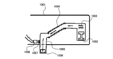
衛生洗浄装置(トイレ装置、温水洗浄便座等を含む)には、洗浄後の局部等を乾燥するための乾燥機構を備えるものが知られている。例えば、特許文献1には、温風を送風する送風機に連通したフレキシブルダクトに移動可能ダクトを進退自在に設け、当該移動可能ダクトの前端に設けた吹出口を使用者の被乾燥部位近くに突出させ、温風を吹きつけ乾燥させる構成の衛生洗浄器が開示されている。この衛生洗浄器においては、前記移動可能ダクトが被乾燥部位に対応する位置に移動したことを検知する検知器が設けられている。前記移動可能ダクトが所定位置に到達したことを検知器が検知すると、送風機および発熱線への通電を開始し、温風が吹出口から噴出する。
As a sanitary washing device (including a toilet device, a warm water washing toilet seat, etc.), a device equipped with a drying mechanism for drying a washed portion or the like is known. For example, in
具体的には、図16に示すように、特許文献1に開示された衛生洗浄器においては、本体1001の内部に設置した送風機1002および発熱線1003からなる温風装置の下流に、フレキシブルダクト1004を設置し、当該フレキシブルダクト1004の下流に移動可能ダクト1005を接続し、当該移動可能ダクト1005の前端部には上方に向かって開口する吹出口1006が設けられている。移動可能ダクト1005の側面にはマグネット1007が設置してあり、本体1001の所定位置にはリードスイッチ1008が設置してある。移動可能ダクト1005が突出した状態では、マグネット1007およびリードスイッチ1008は互いに近接するので、マグネット1007の作用により、リードスイッチ1008が「入」となる。これにより、送風機1002および発熱線1003が通電される。
Specifically, as shown in FIG. 16, in the sanitary washing device disclosed in
また、特許文献2には、温風を送風する送風機に連通した送風ダクトの前端部に温風ノズルを進退自在に設けた構成の乾燥用温風供給装置が開示されている。この乾燥用温風供給装置は、温水洗浄便座に付設されているものであり、非使用時には温風ノズルを送風ダクト内に収納し、使用時には温風ノズルを駆動部によって送風ダクトから進出させるよう構成されている。温風ノズルの前端には温風吹き出し口が設けられているので、使用時には、前記温風噴き出し口は使用者の臀部近くに突出して、乾燥のために温風が臀部に吹きつけられることになる。 Patent Document 2 discloses a drying hot air supply device having a configuration in which a hot air nozzle is provided at a front end portion of a blower duct communicating with a blower that blows hot air. This drying hot air supply device is attached to the hot water washing toilet seat, and when not in use, the hot air nozzle is housed in the air duct, and in use, the hot air nozzle is advanced from the air duct by the drive unit. It is configured. Since the front end of the hot air nozzle is provided with a hot air outlet, the hot air outlet protrudes near the user's buttocks when used, and hot air is blown to the buttocks for drying. Become.
具体的には、図17に示すように、特許文献2に開示された乾燥用温風供給装置においては、本体1011の内部に、送風機1012と送風ダクト1013とが設置され、送風ダクト1013の前端部に温風ノズル1014がスライド自在に挿入されている。温風ノズル1014は駆動装置1015により進退可能に構成され、使用時には、図示されるように、温風ノズル1014の前端の上面に設けられた温風吹き出し口1016が、便座1017の下面後部から使用者の臀部の近くまで突出可能となっている。
Specifically, as shown in FIG. 17, in the hot air supply apparatus for drying disclosed in Patent Document 2, a
あるいは、特許文献3には、運転開始の際に、送風機を回転させた後にヒータを通電させるように構成されたトイレ装置が開示されている。これにより、乾燥運転(暖房運転)の開始の際、急激な温度上昇によって保安器の働きが間に合わなかったとしても、送風によって温度ヒューズの急激な昇温を抑制できるため、これが誤溶断することがない。それゆえ、溶断温度の低い温度ヒューズを採用することができ、異常発生時の温度ヒューズの働きを良好なものとすることができる。なお、このトイレ装置においては、特許文献1および2に開示の技術とは異なり、進退可能な乾燥用の温風ノズル(乾燥ノズル)については記載されていない。
Alternatively, Patent Document 3 discloses a toilet apparatus configured to energize a heater after rotating a blower at the start of operation. As a result, even when the operation of the protector is not in time due to a sudden rise in temperature at the start of the drying operation (heating operation), the rapid rise in temperature of the thermal fuse can be suppressed by blowing air, so this may be blown out by mistake. Absent. Therefore, a temperature fuse having a low fusing temperature can be adopted, and the function of the temperature fuse when an abnormality occurs can be improved. In this toilet apparatus, unlike the techniques disclosed in
このように、衛生洗浄装置が備える乾燥機構としては、乾燥用の温風を吹き出すための乾燥ノズル(特許文献1および2における「温風ノズル」に相当)が使用時に進出する構成のもの(説明の便宜上、「乾燥ノズル進退型」の乾燥機構と称する。)が提案されている。しかしながら、これら乾燥ノズル進退型の乾燥機構においては、何らかの理由で使用時に乾燥ノズルが進出しなかったときに、当該乾燥ノズル内に温風が滞留するという事態を引き起こすおそれがある。
As described above, the drying mechanism included in the sanitary washing apparatus has a configuration in which a drying nozzle (corresponding to the “warm air nozzle” in
例えば、便の付着により乾燥ノズルが進出できなかったり、着衣に由来する糸等の異物が乾燥ノズルの進出を妨げたりした状態が発生したとする。この場合、特許文献3に開示されるように、送風機を先に回転させた後にヒータを通電させたとしても、乾燥ノズルが進出できなければ、乾燥用の温風は乾燥ノズル内に滞る。それゆえ、乾燥ノズルまたは当該乾燥ノズルを含む乾燥機構の内部の温度が所定値以上に過剰に上昇するおそれがある。このような温度上昇は、乾燥機構が備える乾燥ノズル、送風機等の各部材またはデバイスにとって好ましくない。 For example, it is assumed that the drying nozzle cannot advance due to stool attachment or that a foreign matter such as a thread derived from clothes prevents the drying nozzle from entering. In this case, as disclosed in Patent Document 3, even if the heater is energized after rotating the blower first, if the drying nozzle cannot advance, the hot air for drying stays in the drying nozzle. Therefore, the temperature inside the drying nozzle or the drying mechanism including the drying nozzle may be excessively increased to a predetermined value or more. Such a temperature rise is not preferable for each member or device such as a drying nozzle and a blower provided in the drying mechanism.
特に、特許文献3で例示したように、衛生洗浄装置が暖房機能または乾燥機能を有していれば、通常、温度の過剰な上昇を防止する手段(過熱防止器)として、温度ヒューズ等が設けられているが、乾燥ノズル内での温風の滞留は、温度ヒューズの溶断を招くおそれがある。 In particular, as exemplified in Patent Document 3, if the sanitary washing device has a heating function or a drying function, a temperature fuse or the like is usually provided as means (overheat protector) for preventing an excessive increase in temperature. However, the stay of hot air in the drying nozzle may cause the thermal fuse to blow.
乾燥ノズルが進出できない原因が便の付着または異物に起因するものであれば、便または異物を除去すれば、乾燥ノズルは進出可能な状態に容易に復帰する。ところが、温度ヒューズが溶断すれば、復帰が容易な状態であったにもかかわらず、衛生洗浄装置への通電が強制的に遮断され、温度ヒューズを新品に交換する作業をしなければ、復帰させることができなくなってしまう。 If the reason why the drying nozzle cannot advance is due to stool adhesion or foreign matter, the drying nozzle can easily return to a state where advancement is possible if the stool or foreign matter is removed. However, if the thermal fuse is blown out, the power supply to the sanitary washing device is forcibly cut off even though the restoration is easy, and the thermal fuse is restored if it is not replaced with a new one. It becomes impossible to do.
本発明はこのような課題を解決するためになされたものであって、その目的は、乾燥ノズル進退型の乾燥機構を備える衛生洗浄装置において、乾燥ノズルの進出が妨げられた状態となっても、乾燥機構の内部の温度が過剰に上昇する事態を有効に回避できるようにすることにある。 The present invention has been made to solve such a problem, and the object of the present invention is to prevent the advance of the drying nozzle in a sanitary washing apparatus having a drying nozzle advance / retreat type drying mechanism. An object of the present invention is to effectively avoid the situation in which the temperature inside the drying mechanism rises excessively.
本発明に係る衛生洗浄装置は、前記の課題を解決するために、便座と、当該便座を回動自在に支持する本体と、当該本体内に設けられ、前記便座に着座した使用者の局部に向けて洗浄水を噴出可能とする洗浄機構と、前記本体内に設けられ、前記局部に向けて温風を吹出可能とする乾燥機構と、を備え、前記乾燥機構は、前記本体内から外部へ進出可能に設けられる可動ノズルと、前記本体内に位置し、前記可動ノズルを内部に収納可能とする固定ノズルと、を備え、さらに、前記可動ノズルの前端部には、前記固定ノズルから進出して当該前端部が前記局部に面する乾燥位置まで達したときに、当該局部に向かって前記温風を吹出可能とする吹出開口と、前記固定ノズルに収納された収納位置にあるときに、前記温風を当該可動ノズル内から前記本体の外部へ漏出可能とする漏出開口と、が設けられている構成である。 In order to solve the above-described problems, a sanitary washing device according to the present invention provides a toilet seat, a main body that rotatably supports the toilet seat, a local body of a user who is provided in the main body and is seated on the toilet seat. A cleaning mechanism that enables the cleaning water to be ejected toward the outside, and a drying mechanism that is provided in the main body and that allows hot air to be blown toward the local part. A movable nozzle provided so as to be able to advance, and a fixed nozzle that is located in the main body and can accommodate the movable nozzle therein, and further, the front end portion of the movable nozzle advances from the fixed nozzle. When the front end portion reaches the dry position facing the local portion, the blowout opening that allows the warm air to blow toward the local portion, and the storage position stored in the fixed nozzle, Is hot air in the movable nozzle? A leak opening that allows leakage to the outside of the body, is configured to are provided.
前記構成によれば、漏出開口を設けることにより、乾燥ノズルを構成する可動ノズルが収納位置にあっても温風が内部で滞ることが回避される。それゆえ、可動ノズルの進出が妨げられた状態となっても、乾燥機構の内部の温度が過剰に上昇する事態を有効に回避できる。 According to the said structure, even if the movable nozzle which comprises a drying nozzle exists in a storage position by providing a leak opening, it is avoided that a warm air stagnates inside. Therefore, even when the advance of the movable nozzle is hindered, it is possible to effectively avoid a situation in which the temperature inside the drying mechanism rises excessively.
前記衛生洗浄装置においては、前記吹出開口および漏出開口の具体的な構成は特に限定されないが、前記吹出開口は、前記可動ノズルの前端の上面に設けられるとともに、前記漏出開口は、前記前端の端面の上部に、前記吹出開口に連続した切り欠き部として設けられている構成を好ましい一例としてあげることができる。 In the sanitary washing device, specific configurations of the blowout opening and the leak opening are not particularly limited, but the blowout opening is provided on the upper surface of the front end of the movable nozzle, and the leak opening is an end face of the front end. The structure provided as a notch part which followed the said blowing opening in the upper part of can be mentioned as a preferable example.
前記構成によれば、前端の端面に吹出開口に連続した切り欠き部が設けられることで、可動ノズルが収納位置にあっても、当該切り欠き部が漏出開口を構成することになる。それゆえ、吹出開口とは独立した開口を別途設ける必要がなく、可動ノズルの構成を簡素化することができる。 According to the said structure, the notch part which followed the blowing opening in the end surface of a front end is provided, and even if a movable nozzle exists in a storage position, the said notch part comprises a leak opening. Therefore, it is not necessary to separately provide an opening independent of the blowout opening, and the configuration of the movable nozzle can be simplified.
前記衛生洗浄装置においては、前記乾燥機構は、送風機、加熱器、および、当該乾燥機構の温度の過剰な上昇を防止する過熱防止器をさらに備え、前記温風の流れる方向を基準として上流側から、前記送風機、前記過熱防止器、および前記加熱器の順となる位置関係で設けられていることが好ましく、前記乾燥機構は、さらに温度検知器を備え、当該温度検知器は、前記加熱器の下流となる位置に設けられていることがより好ましい。 In the sanitary washing device, the drying mechanism further includes a blower, a heater, and an overheat preventer that prevents an excessive increase in the temperature of the drying mechanism, from the upstream side with respect to the direction in which the hot air flows. It is preferable that the air blower, the overheat preventer, and the heater are provided in a positional relationship. The drying mechanism further includes a temperature detector, and the temperature detector is connected to the heater. More preferably, it is provided at a downstream position.
前記構成によれば、過熱防止器を備えることで、乾燥機構の信頼性をさらに高めることができるだけでなく、可動ノズルに漏出開口が設けられることで、過熱防止器の動作が非常に低い頻度に抑えられる。それゆえ、乾燥機構の動作が停止する可能性も非常に低くすることができる。また、温度検知器が加熱器の下流に設けられることで、加熱器で形成される温風の温度を適切に検出し、乾燥機構の動作を適切なものとすることができる。 According to the said structure, not only can the reliability of a drying mechanism be improved further by providing an overheat protector, but the operation of the overheat protector can be performed at a very low frequency by providing a leak opening in the movable nozzle. It can be suppressed. Therefore, the possibility that the operation of the drying mechanism stops can be very low. Further, by providing the temperature detector downstream of the heater, the temperature of the warm air formed by the heater can be appropriately detected, and the operation of the drying mechanism can be made appropriate.
前記衛生洗浄装置においては、前記過熱防止器として、サーモスタットおよび温度ヒューズが用いられていることが好ましく、前記温度ヒューズは、前記サーモスタットよりも前記送風機に近い位置に設けられていることがより好ましい。 In the sanitary washing apparatus, it is preferable that a thermostat and a thermal fuse are used as the overheat preventer, and it is more preferable that the thermal fuse is provided at a position closer to the blower than the thermostat.
前記構成によれば、過熱防止器を二重に設けていることなるので、信頼性をより好適なものとすることができる。また、非復帰型の過熱防止器である温度ヒューズが送風機に近い位置に設けられていれば、送風機が正常に動作している限り、復帰型の過熱防止器であるサーモスタットよりも先に動作することがない。それゆえ、非復帰型の温度ヒューズの動作を抑制し、必要以上のメンテナンス(点検または修理等)を抑制することができる。 According to the said structure, since the overheat protector is provided double, reliability can be made more suitable. In addition, if the temperature fuse, which is a non-recoverable overheat protector, is provided at a position close to the blower, it will operate before the thermostat, which is a returnable overheat protector, as long as the blower is operating normally. There is nothing. Therefore, the operation of the non-reset type thermal fuse can be suppressed, and unnecessary maintenance (inspection or repair) can be suppressed.
前記衛生洗浄装置においては、制御器および操作器をさらに備え、前記使用者が前記操作器を操作して前記乾燥機構の動作を開始させたときには、前記制御器は、前記送風機および前記加熱器を動作させるとともに、前記温度検知器により検知される温度値の取得し、当該温度値を用いて前記加熱器の出力を調節する制御を行うことが好ましい。 The sanitary washing apparatus further includes a controller and an operation device. When the user operates the operation device to start the operation of the drying mechanism, the controller includes the blower and the heater. It is preferable that the temperature value detected by the temperature detector is acquired and controlled to adjust the output of the heater using the temperature value.
前記構成によれば、使用者が操作器を操作することで、制御器により乾燥機構の動作が開始するよう構成され、かつ、温度検知器によって加熱器の出力が調節されている。それゆえ、使用者の必要に応じて乾燥機構を適切に動作させることができるだけでなく、通常の動作において、乾燥機構の内部の温度が過剰に上昇するおそれを無くすことができる。また、前述した可動ノズルの構成によって、もし可動ノズルの進出が妨げられた状態となっても、乾燥機構の内部の温度が過剰に上昇する事態を有効に回避できる。 According to the above configuration, the operation of the drying mechanism is started by the controller when the user operates the operation device, and the output of the heater is adjusted by the temperature detector. Therefore, not only can the drying mechanism be appropriately operated according to the needs of the user, but also the possibility that the temperature inside the drying mechanism rises excessively during normal operation can be eliminated. In addition, the above-described configuration of the movable nozzle can effectively avoid a situation in which the temperature inside the drying mechanism rises excessively even if the advance of the movable nozzle is hindered.
前記衛生洗浄装置においては、前記制御器は、前記送風機および前記加熱器により形成される前記温風の温度が、予め設定されている乾燥値を超えない温度となるように、前記加熱器の出力を調節する制御を行う構成であると好ましい。 In the sanitary washing apparatus, the controller outputs the heater so that the temperature of the hot air formed by the blower and the heater does not exceed a preset dry value. It is preferable that it is the structure which performs control which adjusts.
前記構成によれば、制御器によって乾燥機構により形成される温風の温度が乾燥値を超えないように制御されるので、通常の動作において好適な温度範囲の温風を形成できるだけでなく、通常の動作において、乾燥機構の内部の温度が過剰に上昇するおそれを無くすことができる。 According to the above configuration, since the temperature of the hot air formed by the drying mechanism is controlled by the controller so as not to exceed the drying value, not only can the hot air in a suitable temperature range be formed in normal operation, In this operation, the possibility that the temperature inside the drying mechanism rises excessively can be eliminated.
前記衛生洗浄装置においては、さらに、前記乾燥機構は、前記可動ノズルを進退させる進退駆動機構をさらに備え、前記使用者が前記操作器を操作して前記乾燥機構の動作を開始させたときには、前記制御器は、前記進退駆動機構による前記可動ノズルの進出を先に開始させた後に、前記可動ノズルが前記乾燥位置に達する前に、前記送風機および前記加熱器の動作を開始させる制御を行う構成であると好ましい。 In the sanitary washing device, the drying mechanism further includes an advance / retreat drive mechanism for moving the movable nozzle back and forth, and when the user operates the operation device to start the operation of the drying mechanism, The controller is configured to perform control to start the operation of the blower and the heater before the movable nozzle reaches the drying position after the advancement of the movable nozzle by the advance / retreat driving mechanism is started first. Preferably there is.
前記構成によれば、可動ノズルが先に動作して、当該可動ノズルが乾燥位置に到達する前に送風機と加熱器への通電を開始することになる。それゆえ、可動ノズルが乾燥位置に到達した時点では、温風の温度を乾燥に好適な範囲に上昇させることができる。したがって、使用者にとっては、温風が吹き出しを開始した時点で、温風の温度は快適な温度範囲となっているので、使用者が冷風感を覚えるおそれが大幅に低減され、使用者に不快感を与える可能性を十分に抑制することができる。 According to the said structure, before a movable nozzle operate | moves previously and the said movable nozzle arrives at a dry position, electricity supply to an air blower and a heater will be started. Therefore, when the movable nozzle reaches the drying position, the temperature of the hot air can be raised to a range suitable for drying. Therefore, for the user, when the hot air starts to blow, the temperature of the hot air is in a comfortable temperature range, so that the possibility that the user feels a cold air is greatly reduced, and the user is inconvenienced. The possibility of giving a pleasant feeling can be sufficiently suppressed.
あるいは、前記衛生洗浄装置においては、前記乾燥機構は、前記可動ノズルを進退させる進退駆動機構をさらに備え、前記使用者が前記操作器を操作して前記乾燥機構の動作を開始させたときには、前記制御器は、前記送風機および前記加熱器の動作を先に開始させてから、前記温風の温度が前記乾燥値に達したことが前記温度検知器により検知されれば、前記進退駆動機構による前記可動ノズルの進出を開始させる制御を構成であってもよい。 Alternatively, in the sanitary washing device, the drying mechanism further includes an advance / retreat drive mechanism for moving the movable nozzle forward and backward, and when the user operates the operation device to start the operation of the drying mechanism, When the controller detects that the temperature of the hot air has reached the dry value after starting the operation of the blower and the heater first, the controller drives the advance / retreat mechanism. The control for starting the advance of the movable nozzle may be configured.
前記構成によれば、温風の温度を乾燥に好適な温度範囲に上昇させ得る状態を確立してから、可動ノズルの進出動作を開始することとなる。そのため、使用者の局部等に冷風が当たることを実質的に防止することができ、使用者に不快感を与える可能性を十分に抑制することができる。 According to the said structure, after the state which can raise the temperature of a warm air to the temperature range suitable for drying is established, the advance operation of a movable nozzle will be started. Therefore, it is possible to substantially prevent the cool air from hitting the user's local area and the like, and the possibility of giving the user discomfort can be sufficiently suppressed.
前記衛生洗浄装置においては、前記いずれかの制御に加えて、前記制御器は、前記加熱器の動作の開始直後は、当該加熱器の出力を、前記温風の前記乾燥値を維持する標準出力値よりも大きい起動出力値とするとともに、前記温度検知器により検知された前記温風の温度が、前記乾燥値よりも低い値として設定されている調節値に達したときには、前記加熱器の出力を、前記起動出力値から前記標準出力値に低下させる制御を行う構成であると、より好ましい。 In the sanitary washing apparatus, in addition to any of the controls described above, the controller outputs the heater output immediately after the start of the operation of the heater, and the standard output for maintaining the dry value of the hot air. And when the temperature of the hot air detected by the temperature detector reaches an adjustment value set as a value lower than the dry value, the output of the heater Is more preferable when the control is performed to reduce the start output value to the standard output value.
前記構成によれば、加熱器の動作を開始させてから一定の期間では、温風の昇温速度を相対的に高くなるように制御し、設定温度である乾燥値に近づいた時点で、昇温速度を低下させるように制御する。これにより、温風の温度が乾燥値をオーバーシュートするおそれが有効に抑制され、それゆえ、温風の温度を短時間で乾燥値まで昇温できるとともに、温風の温度をより適切に調節することが可能となる。 According to the above configuration, the temperature rising rate of the hot air is controlled to be relatively high for a certain period after the operation of the heater is started, and when the temperature approaches the dry value that is the set temperature, the temperature rises. Control to reduce the temperature rate. This effectively suppresses the possibility that the temperature of the hot air overshoots the dry value, and therefore the temperature of the hot air can be raised to the dry value in a short time and the temperature of the hot air is adjusted more appropriately. It becomes possible.
前記衛生洗浄装置においては、前記固定ノズルは、その前端部が下方となるように傾斜した状態で前記本体内に設けられ、前記温度検知器は、前記固定ノズルの後端部において、前記固定ノズル内に前記可動ノズルが収納された状態で前記可動ノズルの内部に露出する位置に設けられている構成であると好ましい。 In the sanitary washing apparatus, the fixed nozzle is provided in the main body in an inclined state so that a front end portion thereof is downward, and the temperature detector is disposed at the rear end portion of the fixed nozzle. It is preferable that the movable nozzle is provided at a position exposed inside the movable nozzle in a state where the movable nozzle is accommodated therein.
前記構成によれば、傾斜して設けられる乾燥ノズル(固定ノズルおよび可動ノズル)の最上方に温度検知器が位置することになる。それゆえ、仮に固定ノズルに洗浄水または尿等の水性液体が流れ込んだ場合であっても、これら水性液体が温度検知器に影響を及ぼすおそれを有効に回避することができる。また、温度検知器は、可動ノズルが収納位置にあっても乾燥位置にあっても、温風の通路内に露出していることになる。それゆえ、加熱器で形成される温風の温度を、より一層適切に検出し、乾燥機構の動作をさらに適切なものとすることができる。 According to the said structure, a temperature detector will be located in the uppermost part of the drying nozzle (a fixed nozzle and a movable nozzle) provided in inclination. Therefore, even if an aqueous liquid such as washing water or urine flows into the fixed nozzle, the possibility that these aqueous liquids affect the temperature detector can be effectively avoided. Further, the temperature detector is exposed in the hot air passage regardless of whether the movable nozzle is in the storage position or the drying position. Therefore, the temperature of the warm air formed by the heater can be detected more appropriately, and the operation of the drying mechanism can be made more appropriate.
前記衛生洗浄装置においては、前記固定ノズルの後端部の下内面は、当該固定ノズルそのものの傾斜角よりも小さな傾斜角を有する平坦面となっており、当該平坦面に、前記温度検知器が設けられていることが好ましく、前記平坦面には、上側に突出する突起部が設けられ、当該突起部に前記温度検知器が位置していることがより好ましい。 In the sanitary washing apparatus, the lower inner surface of the rear end portion of the fixed nozzle is a flat surface having an inclination angle smaller than the inclination angle of the fixed nozzle itself, and the temperature detector is disposed on the flat surface. Preferably, the flat surface is provided with a protruding portion protruding upward, and the temperature detector is more preferably located on the protruding portion.
前記構成によれば、温度検知器が加熱器の下流側に位置し、平坦面は固定ノズルの後端部の下内面であるので、温度検知器が設けられる位置は、加熱器の下流であり、かつ、傾斜した固定ノズルと加熱器との接続部に相当する。それゆえ、乾燥機構に温度検知器を設けるための特別な部位を形成しなくても、固定ノズルの後方側に平坦面を設けるだけで温度検知器を設ける部位とすることができるので、乾燥機構の大型化を抑制することができる。また、平坦面は、固定ノズルの傾斜角より緩やかに傾斜しているので、固定ノズル内に水性液体が勢いよく流入したとしても、固定ノズル内に露出した温度検知器は、水性液体の流入方向より下方に位置することになるので、当該水性液体が温度検知器にかかるおそれを有効に抑制することができる。加えて、突起部に温度検知器が設けられていれば、流れ落ちた水性液体が温度検知器に接触するおそれも有効に抑制できる。 According to the above configuration, the temperature detector is located downstream of the heater, and the flat surface is the lower inner surface of the rear end portion of the fixed nozzle. Therefore, the position where the temperature detector is provided is downstream of the heater. And it corresponds to the connecting portion between the inclined fixed nozzle and the heater. Therefore, even if a special part for providing the temperature detector in the drying mechanism is not formed, the temperature sensor can be provided only by providing a flat surface on the rear side of the fixed nozzle. Increase in size can be suppressed. Further, since the flat surface is inclined more gently than the inclination angle of the fixed nozzle, even if the aqueous liquid flows into the fixed nozzle vigorously, the temperature detector exposed in the fixed nozzle Since it will be located below, the possibility that the aqueous liquid may be applied to the temperature detector can be effectively suppressed. In addition, if the temperature detector is provided on the protrusion, it is possible to effectively suppress the possibility that the aqueous liquid that has flowed down contacts the temperature detector.
前記衛生洗浄装置においては、前記可動ノズルの後端部には、前記可動ノズルが前記固定ノズル内に収納されたときに、前記温度検知器が露出できる長さとなるように、前側に切り込まれた切り込み部が設けられていることが好ましい。 In the sanitary washing device, a rear end portion of the movable nozzle is cut forward so that the temperature detector can be exposed when the movable nozzle is housed in the fixed nozzle. It is preferable that a cut portion is provided.
前記構成によれば、可動ノズルが固定ノズルに収納された状態(収納位置)において、平坦面に設けられた温度検知器が可動ノズル内に露出することができる。 According to the above configuration, in a state where the movable nozzle is accommodated in the fixed nozzle (accommodated position), the temperature detector provided on the flat surface can be exposed in the movable nozzle.
前記衛生洗浄装置においては、前記固定ノズル内に前記可動ノズルが収納された状態で、当該可動ノズルの下方外面と前記固定ノズルの下内面との間には、前記温度検知器が設けられている位置から前記固定ノズルの後端部に達する溝状の間隙が設けられていることが好ましい。 In the sanitary washing apparatus, the temperature detector is provided between a lower outer surface of the movable nozzle and a lower inner surface of the fixed nozzle in a state where the movable nozzle is housed in the fixed nozzle. It is preferable that a groove-like gap reaching from the position to the rear end of the fixed nozzle is provided.
前記構成によれば、固定ノズルの内面に溝状の間隙が設けられることになるので、固定ノズルと可動ノズルとの接触面積が小さくなり、固定ノズル内での可動ノズルの摺動抵抗を軽減することができる。また、固定ノズル内に水性液体が侵入したとしても、溝状の間隙を流れて固定ノズルの外へ排出されやすくなる。 According to the above configuration, since the groove-shaped gap is provided on the inner surface of the fixed nozzle, the contact area between the fixed nozzle and the movable nozzle is reduced, and the sliding resistance of the movable nozzle within the fixed nozzle is reduced. be able to. Further, even if an aqueous liquid enters the fixed nozzle, it tends to flow through the groove-like gap and be discharged out of the fixed nozzle.
以上のように、本発明によれば、乾燥ノズル進退型の乾燥機構を備える衛生洗浄装置において、乾燥ノズルの進出が妨げられた状態となっても、乾燥機構の内部の温度が過剰に上昇する事態を有効に回避することができるという効果を奏する。 As described above, according to the present invention, in the sanitary washing apparatus including the drying nozzle advance / retreat type drying mechanism, the temperature inside the drying mechanism rises excessively even when the advancement of the drying nozzle is hindered. There is an effect that the situation can be effectively avoided.
以下、本発明の好ましい実施の形態を、図面を参照しながら説明する。なお、以下では全ての図を通じて同一又は相当する要素には同一の参照符号を付して、その重複する説明を省略する。 Hereinafter, preferred embodiments of the present invention will be described with reference to the drawings. In the following description, the same or corresponding elements are denoted by the same reference symbols throughout the drawings, and redundant description thereof is omitted.
(実施の形態1)
[衛生洗浄装置の外観構成]
まず、本実施の形態に係る衛生洗浄装置の外観構成について、図1を参照して具体的に説明する。図1は、本実施の形態に係る衛生洗浄装置100を便器600の上に設置した状態の外観を示す斜視図である。
(Embodiment 1)
[External configuration of sanitary washing equipment]
First, the external configuration of the sanitary washing apparatus according to the present embodiment will be specifically described with reference to FIG. FIG. 1 is a perspective view showing an appearance of a state in which the
以下、衛生洗浄装置100の構成を説明するにあたっては、便座400に着座した使用者から見て前方を前方向または前側、後方を後方向または後側、左側方を左方向または左側、右側方を右方向または右側として説明する。この場合、本体200を便器600へ設置した状態で、当該本体200の側が後側となり、便座400の側が前側となる
また、便蓋300および便座400は、それぞれ起立位置と倒伏位置との間で、それぞれ別個にかつ両者一緒に回動可能に設けられるが、以下では、便宜上、これらが倒伏位置から起立位置へ向かって回動することを「開く」といい、起立位置から倒伏位置へ向かって回動することを「閉じる」という。
Hereinafter, in describing the configuration of the
図1に示すように、衛生洗浄装置100は、本体200、便蓋300、便座400、リモートコントローラ500を備え、本体200、便蓋300、便座400は一体で構成され、便器600の上面に設置される。
As shown in FIG. 1, the
本体200には、便蓋300および便座400が回動自在に支持されている。本実施の形態では、便蓋300および便座400は、本体200内に設けられる電動の便座便蓋開閉ユニット(図示せず)を介して当該本体200に取り付けられ、それゆえ、手動による開閉も自動的な開閉もいずれも可能となるように構成されている。図1に示すように、便蓋300を開いた状態においては、便蓋300は衛生洗浄装置100の最後部となる位置で起立状態となる。また、便蓋300を閉じた状態においては、図示しないが、便座400の上面を覆うことで、便座400と便器600の内部とを隠蔽する。本実施の形態では、便座400は、便座ヒータ(図示せず)を内蔵しており、当該便座ヒータの加熱により、便座400の着座面が快適な温度になるように暖房される。
On the
また、本実施の形態では、図1に示すように、本体200の右側部には突出部が設けてあり、この突出部の前部には人体検知センサ201が設けられている。また、本体200の前面で便座400が倒伏位置にある状態で、当該便座400の上面よりも上側となる位置(図1に示す構成では、本体200の前上方のコーナー部)には、着座センサ202が設けられている。これら人体検知センサ201および着座センサ202は、本実施の形態では、反射型の赤外線センサが用いられる。赤外線センサは赤外線を放射し、当該赤外線が人体で反射されれば、それを検出することにより人体を検知するよう構成されている。なお、人体検知センサ201はトイレ室に入室した使用者を検知するものであり、着座センサ202は便座400に着座した使用者を検知するものである。
In the present embodiment, as shown in FIG. 1, a protrusion is provided on the right side of the
リモートコントローラ500は、衛生洗浄装置100の操作器であって、衛生洗浄装置100が設置されたトイレ室において、便座400上に着座した使用者が操作可能な位置の壁面に取り付けられる。リモートコントローラ500には、衛生洗浄装置100を操作するために、複数の操作スイッチおよび表示部が設けられている。
さらに、図1には詳細に示さないが、本体200の右側部に設けられている前記突出部にも、リモートコントローラ500の操作機能を補助するための操作スイッチおよび表示部等が設けられてもよい。
The
Further, although not shown in detail in FIG. 1, an operation switch and a display unit for assisting the operation function of the
前述した本体200、便蓋300、便座400、リモートコントローラ500の具体的構成、並びに、リモートコントローラ500が備える操作スイッチおよび表示部等の具体的構成は特に限定されるものではなく、いずれも公知の構成を好適に用いることができる。
Specific configurations of the
また、本体200の前側下部は便器600の内部に向かっており、便座400の下に位置しているが、この部位の中央部には、ノズルシャッター203が設けられている。このノズルシャッター203は、本体200内に収納された各種洗浄ノズル、乾燥ノズルの先端部を覆うものである。ノズルシャッター203、洗浄ノズル、および乾燥ノズルについては後述する。
In addition, the front lower portion of the
[本体内部の構成]
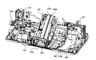
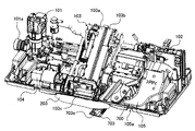
次に衛生洗浄装置100が備える本体200の内部構成について、図2ないし図4を参照して具体的に説明する。図2は、本体200のカバーを外した状態を示す斜視図であって、後述する可動ノズルが収納位置(後述)にある状態の一例を示す図であり、図3は、図2と同様に、本体200のカバーを外した状態を示す斜視図であって、前記可動ノズルが乾燥位置(後述)にある状態の一例を示す図である。図4は、図2および図3と同様に、本体200のカバーを外した状態を示す斜視図であるが、図2および図3には示されていない制御ユニットの位置を示す図となっている。
[Internal configuration]
Next, the internal configuration of the
図2および図3に示すように、本体200のカバーを取り外した状態では、本体200の内部には、給水ユニット101、熱交換器102、洗浄ノズルユニット103、エアポンプ104、脱臭ユニット105、乾燥ユニット700等が設けられている。また、図2および図3には図示されないが、便座便蓋開閉ユニットも本体200内に設けられ、図4に示すように、制御ユニット204も本体200内に設けられている。なお、給水ユニット101、熱交換器102、洗浄ノズルユニット103、脱臭ユニット105、乾燥ユニット700、便座便蓋開閉ユニット、制御ユニット204等は、衛生洗浄装置100が有する各種機能を実行するためのユニットであるので、以下の説明では、必要に応じて、まとめて機能ユニットと称する。
2 and 3, when the cover of the
給水ユニット101は、洗浄ノズルユニット103へ洗浄水を供給する洗浄水供給機構(給水手段)である。給水ユニット101は給水口101aを有し、この給水口101aを介して、洗浄水の供給源である水道配管に接続される。また、給水ユニット101は、熱交換器102を介して洗浄ノズルユニット103に接続されている。
The
熱交換器102は、給水ユニット101から供給された洗浄水を加熱して所定の温度範囲の温水を調製するもの(熱交換ユニット、洗浄水加熱手段)である。熱交換器102は、前記のとおり給水ユニット101および洗浄ノズルユニット103の間に介在して接続されている。
The
洗浄ノズルユニット103は、お尻洗浄ノズル103a、ビデノズル103b、これらを進退移動させる洗浄ノズル駆動機構(図示せず)等を備えている。リモートコントローラ500の操作により、お尻洗浄ノズル103aまたはビデノズル103bは本体200から進出し、熱交換器102から供給される温水を使用者の局部へ噴出させることにより、当該局部を洗浄する。すなわち、洗浄ノズルユニット103は、便座400に着座した使用者の局部に向けて洗浄水を噴出可能とする洗浄機構(洗浄手段)である。
The cleaning
洗浄ノズルユニット103が備えるお尻洗浄ノズル103aは、男女共通で肛門およびその近傍の局部を洗浄するために用いられ、ビデノズル103bは、女性の局部を洗浄するために用いられる。つまりお尻洗浄ノズル103aおよびビデノズル103bは、いずれも局部を洗浄する洗浄ノズルであり、これら洗浄ノズルは、本体200内に収納された収納位置(図2および図3参照)と、洗浄動作を行うための位置であって、本体200の前方に設けられるノズル進出口103cから前方に進出した洗浄位置(図示せず)との間を、前記洗浄ノズル駆動機構により進退移動する。
The
エアポンプ104は、洗浄水に空気を混入するためのものであり、本実施の形態では、洗浄ノズルユニット103とともに、洗浄機構の一部を構成している。洗浄水に空気を混入することで、局部に当接する洗浄水の勢いを緩和させたり、局部へマッサージ効果を与えたりすることができる。なお、エアポンプ104は設けられなくてもよい。なお、洗浄ノズルユニット103に温水を供給するための給水ユニット101および熱交換器102も洗浄機構(洗浄手段)の一部を構成している。
The
脱臭ユニット105は、便器600内および衛生洗浄装置100近傍の脱臭を行うもの(脱臭装置、脱臭手段)である。脱臭ユニット105は、脱臭を行うために空気を吸い込む吸込口105aを備えているが、この吸込口105aは、通常、図2および図3に示すように、便器600内の排便臭を吸い込むために本体200の前側に設けられている。
The
乾燥ユニット700は、洗浄水により濡れた局部の乾燥を促進するために、当該局部に向けて温風(乾燥風)を噴出するものであり、局部に向けて温風を吹出可能とする乾燥機構(乾燥装置、乾燥手段)である。乾燥ユニット700は、図3に示すように、本体200内から外部へ進出可能に設けられる可動ノズル703を少なくとも備えている。この可動ノズル703には、温風を吹き出すための吹出口703e(あるいは温風の噴出口)が設けられている。なお、乾燥ユニット700の具体的な構成については後述する。
The drying
本実施の形態に係る衛生洗浄装置100においては、本体200の前側下部から突出可能な構成として、お尻洗浄ノズル103a、ビデノズル103b、および可動ノズル703を備えている。これらをまとめて突出部材と称すれば、これら突出部材は、通常は、図2に示すように本体200の内部に収納されている。
The
ここで、本実施の形態では、図1にも示すように、本体200の前方下部を覆う位置にノズルシャッター203が設けられている。このノズルシャッター203は、前記突出部材が本体200内に収納されているときには、本体200の前側下部を覆っているが、図3に示すように、前記突出部材のいずれかが進出すれば上側に開くように取り付けられている。なお、図3では可動ノズル703が進出した例を示している。これにより、排便時に汚物等が前記突出部材に直接掛からないようにすることができる。なお、このノズルシャッター203は、本実施の形態では、汚れが付着した時には洗浄ができるよう、着脱可能な構成となっている。
Here, in the present embodiment, as shown in FIG. 1, the
さらにノズルシャッター203を開く動作は、本実施の形態では、前記突出部材のうち、洗浄ノズルユニット103が備えるお尻洗浄ノズル103aおよびビデノズル103bによって行われる。具体的には、通常、ノズルシャッター203は図示されないバネ等の弾性部材により閉じた状態(図2参照)に付勢されている。そして、局部の洗浄が行われる場合であれば、お尻洗浄ノズル103aまたはビデノズル103b自体が進出してノズルシャッター203に当接して押し上げることで(図3参照)、当該ノズルシャッター203が開けられることになる。
Further, in the present embodiment, the operation of opening the
次に、局部の乾燥が行われる場合であれば、まずビデノズル103bが進出を開始してノズルシャッター203に当接し、ノズルシャッター203を開いた状態で停止する。次に、可動ノズル703が、ビデノズル103bより遅れて進出を開始する。ノズルシャッター203は、ビデノズル103bによって押し上げられて開いた状態にあるので、その下方より可動ノズル703が便器600の中央に向かって突出する。可動ノズル703が完全に突出した状態では、可動ノズル703の吹出口703eはノズルシャッター203で閉塞されない位置に設けられているので、当該吹出口703eから温風が局部に向かって吹き出されることになる。
Next, if local drying is performed, first, the
なお、乾燥時にビデノズル103bでノズルシャッター203を開ける理由は、乾燥ユニット700が本体200の中央から外れた位置に設けられるためである。すなわち、ノズルシャッター203は、本体200の前側下部の中央に設けられているが、乾燥ユニット700が偏った位置に設けられていれば、必然的に可動ノズル703もノズルシャッター203の一方の側に偏って配置されていることになる。それゆえ、可動ノズル703自体でノズルシャッター203を確実に開くことが難しいことから、本体200の中央に位置するビデノズル103bを用いる。
The reason why the
もちろん、お尻洗浄ノズル103aによりノズルシャッター203を開けてもよいし、ステッピングモータ等のシャッター開閉用の駆動機構を別途設けることにより、ノズルシャッター203を開くように構成してもよい。なお、乾燥ユニット700の本体200内での具体的な位置に関しては後述する。
Of course, the
また、図4に示すように、本体200の内部には、制御ユニット204が設けられている。この制御ユニット204は、リモートコントローラ500、人体検知センサ201および着座センサ202から送信される信号に基づいて、衛生洗浄装置100の各部の動作を制御する。本実施の形態では、制御ユニット204は、メイン制御部204a、サブ制御部204b,204cから構成されている。
As shown in FIG. 4, a
制御ユニット204による制御の一例について説明すると、例えば、トイレ室に使用者が存在しない場合には、制御ユニット204は、便座400内の便座ヒータへの通電を停止もしくは20℃程度の低温に保温している。トイレ室に使用者が入室すると、制御ユニット204は、人体検知センサ201からの信号を受けて便座ヒータに通電を行う。便座ヒータは800W程度の非常に高出力のヒータであり、使用者がトイレ室に入室してから便座400に着座するまでの6秒から10秒程度の間に、便座400の着座面を40℃程度の適温に温める。便座400が適温に達した後には、制御ユニット204は、便座ヒータへの通電を50W程度の低ワットに下げ、適温を保つ。使用者がトイレ室から出ると、制御ユニット204は、便座ヒータへの通電を停止もしくは20℃程度の低温保温とする。このように、本実施の形態に係る衛生洗浄装置100は、制御ユニット204により、トイレ室に使用者がいないときの電力を大幅に削減できるように制御されている。
An example of the control by the
さらに、図示されない便座便蓋開閉ユニットは、前述したように、便蓋300および便座400を自動的に開閉させるものであり、便蓋300および便座400の回動軸を電動で回転させることで、これらを回動する便座便蓋回動機構として構成されている。
Further, the toilet seat toilet lid opening / closing unit (not shown) automatically opens and closes the
[機能ユニットの位置関係]
次に、前記構成の衛生洗浄装置100において、本体200内の各機能ユニット等の位置関係について、図2ないし図4を参照して具体的に説明する。
[Relationship of functional units]
Next, in the
前述したように、本体200の内部には、機能ユニットとして、給水ユニット101、熱交換器102、洗浄ノズルユニット103、脱臭ユニット105、乾燥ユニット700、制御ユニット204、便座便蓋開閉ユニット等が設けられている。
As described above, the
このうち、洗浄ノズルユニット103は、衛生洗浄装置100において最も重要な機能ユニットの一つであり、便座400に着座した使用者の局部を洗浄するために、お尻洗浄ノズル103aおよびビデノズル103bを本体200の外に突出させる必要がある。また、お尻洗浄ノズル103aおよびビデノズル103bは、局部まで届く程度の長さを有しているので、本体200の内部では、当該本体200の大型化を回避する上で、お尻洗浄ノズル103aおよびビデノズル103bを傾斜して配置させることになる。それゆえ、基本的に、洗浄ノズルユニット103は、本体200の中央部に配置される。これにより、ノズル進出口103cは、本体200の前側下部の中央に位置する。
Among them, the cleaning
ここで、エアポンプ104は、前述したように、洗浄水に空気を混入させるものであるため、洗浄ノズルユニット103に近接して配置されることが好ましい。本実施の形態では、図2ないし図4に示すように、洗浄ノズルユニット103の右側(図面上では向かって左側)に設けられている。
Here, as described above, since the
また、給水ユニット101は、本体200の外部から内部に洗浄水を給水するための機能ユニットであるため、本体200の左右いずれかの端部に配置しなければならない。本実施の形態では、給水ユニット101は、右端部(図面上では向かって左側)に設けられているが、左端部でもよい。
Further, since the
また、便座便蓋開閉ユニットは、本体200の上方で回動可能に設けられる便蓋300および便座400を開閉させるものであるため、本体200の上寄りに設けられることが好ましい。本実施の形態では、給水ユニット101および洗浄ノズルユニット103の間となる右寄り上方の空間に設けられている(図面上では向かって左上方の空間)。
Further, since the toilet seat toilet lid opening / closing unit is for opening and closing the
また、脱臭ユニット105は、便器600内の排便臭を除去する観点から、できれば本体200の中央部に設けることが好ましい。しかしながら、前記のとおり中央部には洗浄ノズルユニット103を優先して設ける必要があること、並びに、便器600内の排便臭を吸い込む吸込口105aを、本体200の前側下部において中央部にできるだけ近い位置に設けることができれば、当該脱臭ユニット105そのものの位置を制限する条件はほとんどない。それゆえ、脱臭ユニット105は、本実施の形態では、本体200の左端部(図面上では向かって右側)に設けられ、吸込口105aのみがダクトにより中央部よりに設けられている。
Moreover, it is preferable to provide the
ここで、熱交換器102および制御ユニット204の寸法は、他の機能ユニットに比べると相対的に小さい。それゆえ、本体200の形状を考慮して、優先すべき他の機能ユニットを配置させてから、空いている残りの空間に適宜配置させることができる。例えば、本実施の形態では、熱交換器102は、本体200の左寄り後部(図面上では向かって右寄り後部)に設けられ、前方に乾燥ユニット700が位置している。また、制御ユニット204は、図4に示すように、洗浄ノズルユニット103、乾燥ユニット700、熱交換器102の上方の空間に配置されている。
Here, the dimensions of the
本実施の形態では、衛生洗浄装置100が乾燥ユニット700を備えているが、この乾燥ユニット700は、使用者の局部に温風を吹出する必要があるため、やはり本体200の中央部に位置することが好ましい。しかしながら、前記のとおり中央部には洗浄ノズルユニット103を優先して設ける必要があるので、基本的には、洗浄ノズルユニット103に隣接させて中央部よりの位置に設けられる。本実施の形態では、本体200の中央部左寄り(図面上では向かって中央の右寄り)に設けられる。
In the present embodiment, the
なお、前述したとおり、脱臭ユニット105においては吸込口105aの位置が中央部に近ければよいことから、本体200の中央部に設けられる機能ユニットの優先順位は、高い順から、洗浄ノズルユニット103、乾燥ユニット700、および脱臭ユニット105となる。
As described above, in the
このように、乾燥ユニット700は、本体200の中央部に近いものの、中央部から左右に寄った位置に設けられざるを得ない。したがって、乾燥ユニット700が備える可動ノズル703は、洗浄ノズルユニット103の側方に位置する収納位置(後述)から、中央部の前側下方に向かって斜めとなる乾燥位置(後述)に向かって突出するよう構成されている。また、可動ノズル703に設けられている吹出口703eも、中央部に向かって温風を吹き出すことができるような独自の形状を有している。この点については後述する。
Thus, although the
なお、給水ユニット101、熱交換器102、洗浄ノズルユニット103、脱臭ユニット105、乾燥ユニット700、制御ユニット204、および便座便蓋開閉ユニット等の具体的な構成については特に限定されず、乾燥ユニット700が備える可動ノズル703等の独自の構成(後述)を除けば、公知の各種の構成が好適に用いられる。
これらユニットの具体的な構成は特に限定されない
[乾燥ユニットの全体構成]
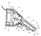
次に、本実施の形態における乾燥ユニット700の具体的な構成について、図5ないし図8を参照して具体的に説明する。図5は、乾燥ユニット700の外観構成の一例を示す斜視図であり、図6および図7は、乾燥ユニット700の概略断面図である。このうち、図6は可動ノズル703が収納位置にある状態を示し、図7は可動ノズル703が乾燥位置にある状態を示している。また、図8は、図7に示す乾燥ユニット700のAA線矢視断面図である。また、図9は、乾燥ユニット700が備えるヒータユニット708の構成の一例を示す斜視図であり、ヒータユニット708を後方から見た図である。
The specific configurations of the
The specific configuration of these units is not particularly limited [Overall configuration of drying unit]
Next, a specific configuration of the
図4ないし図6に示すように、乾燥ユニット700は、ケース701、固定ノズル702、可動ノズル703、駆動モータ704、ギア機構705、ヒータユニット708、ファンモータ709、サーミスタ710等により構成されている。
4 to 6, the drying
乾燥ユニット700の外装となるケース701は、図5に示すように、本実施の形態では、例えば難燃性樹脂により成形された上ケース701aと下ケース701bとを上下に結合した構成となっている。
As shown in FIG. 5, the
図6および図7に示すように、ケース701は、内部に略トンネル状の空洞部が形成された構成となっており、前後端には空気流の出入口となる開口が設けられている。このうち、空気流の入口となる側は後端開口701cであって、空気流の出口となる側は前端開口701dである。また、前端開口701dの近傍はケース701の前端部であるとともに固定ノズル702となっている。
As shown in FIGS. 6 and 7, the
ケース701の内部には、後端開口701cから前端開口701dに向かって順に、ファンモータ709、ヒータユニット708、サーミスタ710、可動ノズル703が設けられている。後端開口701cの近傍であるケース701の後端部は、ヒータユニット708およびファンモータ709を配置するために、前端部(固定ノズル702)よりも内径が大きく設定されている。それゆえ、ケース701は、後端開口701cから前方に向かって断面積が小さくなるように収束し、前端部は一定の断面積を有する筒状の固定ノズル702となっているので、その全体形状は漏斗状であると見なすことができる。
Inside the
ファンモータ709は、ケース701のトンネル状の空洞部内で空気流を形成するための送風機であり、ファンモータ709の動作により後端開口701cからケース701内に空気が導入され、前端開口701dに向かって空気流が送風される。ファンモータ709の前側にはヒータユニット708が設けられているので、当該空気流はヒータユニット708により暖められることにより、温風が形成される。つまり、ヒータユニット708は、空気流を加熱する加熱器となっている。
The
形成された温風は、サーミスタ710および可動ノズル703の内部を通過して、可動ノズル703の先端部に設けられる吹出口703eから吹き出される(あるいは噴出される)。ここで、ケース701は漏斗状であることから、後端開口701cから導入された空気流は可動ノズル703を通過するまで集約されて高速化する。それゆえ、吹出口703eから吹き出される温風は付勢されて局部に当てられることになる。また、サーミスタ710は、温度検知器であり、前述した制御ユニット204に温度情報を信号として出力する。制御ユニット204は、サーミスタ710で検知された温度に基づいて乾燥ユニット700における温風温度の制御を行う。
The formed warm air passes through the
ケース701の後端部を基準とすれば、前端部すなわち固定ノズル702は、後部より前部が下がるように下側に傾斜している。これは、乾燥ユニット700を本体200内に設けたときに、前端開口701dが本体200の前側下部に位置させるためである。固定ノズル702は、本実施の形態では、その断面形状が略長方形の筒状であり、その下方の内面は傾斜面702aとなっている。それゆえ、傾斜面702aを形成する固定ノズル702の下壁部は傾斜部と見なすことができる。
If the rear end portion of the
固定ノズル702は、図6に示すように、内部に可動ノズル703を収納可能としており、この位置を可動ノズル703の収納位置と称する。また、可動ノズル703は、後述するように、固定ノズル702の内部で摺動自在に設けられ、図7に示すように、前端開口701dから固定ノズル702の外部に進出可能となっている。この進出した位置は、便器600内で便座400に着座した使用者の局部に、当該可動ノズル703の前端部が面した位置に相当し、可動ノズル703の乾燥位置と称する。なお、本実施の形態では、固定ノズル702および可動ノズル703により乾燥ノズルが構成される。
As shown in FIG. 6, the fixed
固定ノズル702における傾斜面702aの最上部、すなわち、固定ノズル702の後端側でヒータユニット708が設けられている位置に隣接する部位には、傾斜面702aに連接して、当該傾斜面702aよりも傾斜の緩やかな平坦面702cが設けられている。つまり、固定ノズル702は、その前端部が下方となるように傾斜した状態で本体200内に設けられている。そして、固定ノズル702の後端部の下内面は、当該固定ノズル702そのものの傾斜角(つまり傾斜面702aの傾斜角)よりも小さな傾斜角を有する平坦面702cとなっている。この平坦面702cを形成する固定ノズル702の後端側下壁部は平坦部と見なすことができる。
The uppermost portion of the
この平坦面702cには、本実施の形態では、その略中央となる位置に、上方に突出した略円筒状の突起部702dが設けられている。そして、この突起部702dの略中央にはサーミスタ710が取り付けられている。通常、サーミスタ710の温度測定部は外郭を金属で形成されているが、この構成を採用することによって、仮に固定ノズル702に洗浄水または尿等の水性液体が流れ込んだ場合であっても、平坦面702cに流れ落ちた水性液体がサーミスタ710へ接触するおそれを有効に回避することができる。
In the present embodiment, the
また、サーミスタ710は温度検知器であるため、加熱器であるヒータユニット708の下流となる位置に設けられている必要がある。ここで平坦面702cはヒータユニット708の下流であり、かつ、傾斜した固定ノズル702とヒータユニット708との接続部に相当する。サーミスタ710を設けるための特別な部位を形成しなくても、傾斜面702aの後方側を平坦面702cとするだけでサーミスタ710を設けることができるので、乾燥ユニット700の大型化を抑制することができる。また、平坦面702cは、傾斜面702aより緩やかに傾斜しているので、固定ノズル702内に水性液体が勢いよく流入したとしても、固定ノズル702内に露出したサーミスタ710は、水性液体の流入方向より下方に位置することになるので、当該水性液体がサーミスタ710にかかるおそれを有効に抑制することができる。なお、後述するが、可動ノズル703は、収納位置にあるときに、その後端がサーミスタ710に接触しないように構成されている。
Further, since the
本実施の形態においては、可動ノズル703の前端部に設けられた吹出口703eは、後記に詳述するが、上方に向いて開口していることに加え、吹出口703eに連続して複数の切り欠き部が設けられている。それゆえ、使用時に可動ノズル703内に前記水性液体が浸入する可能性がある。
In this embodiment, the
また、衛生洗浄装置100は使用中に尿や便で汚れることから、清掃のために突出部材(お尻洗浄ノズル103a、ビデノズル103b、可動ノズル703)およびその周辺を水洗いすることが必要であるが、突出部材の中でも可動ノズル703は、送風を目的とするために吹出口703eの開口面積が相対的に大きく、かつ、切り欠き部を有しているため、さらに一層開口面積が大きくなる。また可動ノズル703の断面積もお尻洗浄ノズル103a等に比べれば広く構成されている。それゆえ、清掃時の洗浄水が可動ノズル703および固定ノズル702内を通ってサーミスタ710、ヒータユニット708、あるいはファンモータ709近辺にまで到達するおそれがある。
Further, since the
このうち、サーミスタ710に水性液体が付着すれば、検知される温度に誤差が発生し、設定温度を超える高温の温風が吹出口703eから吹き出す可能性が生じる。また、ヒータユニット708またはファンモータ709に水性液体が付着した場合には、錆を発生させたり故障の原因となったりするおそれがある。
Among these, if an aqueous liquid adheres to the
これに対して、本実施の形態では、平坦面702cを形成することで、水性液体が乾燥ユニット700の後端側に侵入しにくくなる。それゆえ、サーミスタ710で検知される温度に誤差が発生するおそれを抑制でき、また、ヒータユニット708またはファンモータ709への影響を回避することができる。特に、サーミスタ710に関しては、平坦面702cに突起部702dを設けて、この突起部702dにサーミスタ710を配置することで、水性液体への接触をより好適に回避することができる。
On the other hand, in the present embodiment, by forming the
なお、本実施の形態では、固定ノズル702の後端部に、傾斜面702aにつながる平坦面702cを設けているが、本発明はこれに限定されず、少なくともサーミスタ710等の温度検知器が、固定ノズル702の後端部において、当該固定ノズル702内に可動ノズル703が収納された状態(収納位置にある状態)で、可動ノズル703の内部に露出する位置に設けられていればよい。これにより、傾斜面702aの最上方に温度検知器が位置することになるので、この構成だけでも水性液体による影響を有効に回避することができる。まら、サーミスタ710は、可動ノズル703が収納位置にあっても乾燥位置にあっても、温風の通路内に露出していることになるので、温風の温度をより一層適切に検出し、乾燥ユニット700の動作をより適切に制御することができる。
In this embodiment, a
また、本実施の形態では、図8に示すように、固定ノズル702と可動ノズル703との間に溝状間隙702eが設けられることがより好ましい。具体的には、図8の断面図に示すように、傾斜面702aには、例えば高さ約0.5mmの摺動面リブ702bが傾斜方向に沿って線状に設けられ、これにより、可動ノズル703と固定ノズル702との間に溝状間隙702eが形成される。この溝状間隙702eの存在により、固定ノズル702と可動ノズル703との接触面積が小さくなり、固定ノズル702内での可動ノズル703の摺動抵抗を軽減することができる。さらに、固定ノズル702内に侵入した水性液体が溝状間隙702eを流れ、前端開口701dから排出されやすくなる。
In the present embodiment, as shown in FIG. 8, it is more preferable that a groove-
なお、溝状間隙702eの具体的構成はこれに限定されず、傾斜面702aに摺動面リブ702bを設けるのではなく、可動ノズル703の下方の外面(本実施の形態では、略平坦な裏面703m、図11参照)に同様のリブを設けてもよいし、傾斜面702aおよび裏面703mの双方にリブを設けてもよい。また、摺動面リブ702b以外の突起部により実現されてもよいし、傾斜面702aに溝が刻まれたり、逆に可動ノズル703の裏面703mに溝が刻まれたりする構成であってもよい。すなわち、本発明においては、固定ノズル702内に可動ノズル703が収納された状態で、当該可動ノズル703の下方外面(裏面)と固定ノズル702の下内面(傾斜面702a)との間には、サーミスタ710等の温度検知器が設けられている位置から固定ノズル702の後端部(前端開口701d)に達する溝状の間隙が設けられていればよい。
The specific configuration of the groove-
また、本実施の形態における乾燥ユニット700の具体的構成は、後述する可動ノズル703の基本構成を除いて前述した構成に限定されない。例えば、乾燥ユニット700はファンモータ709、ヒータユニット708およびサーミスタ710を備える構成に限定されず、例えば、ファンモータ709に代えて他の送風機を用いてもよいし、サーミスタ710に代えて他の温度検知器を用いてもよい。
Further, the specific configuration of the
ここで、本実施の形態においては、ヒータユニット708は過熱防止器を一体的に備えているとより好ましい。過熱防止器とは、空気流を加熱する温度が過剰に上昇することを回避または防止する手段(温度過昇防止手段)であり、ヒータユニット708とは別体の独立した部材として設けられてもよいが、ヒータユニット708と一体化することで、乾燥ユニット700のより小型化を図ることができる。
Here, in the present embodiment, it is more preferable that the
本実施の形態におけるヒータユニット708は、図9に示すように、約340Wの螺旋状のヒータ線708aが、外郭となるカバーマイカ708d内に設けられている。言い換えれば、カバーマイカ708dはヒータユニット708の筐体として機能している。さらに、カバーマイカ708d内には、113℃で動作する温度ヒューズ708bと94℃で動作するサーモスタット708cとが取り付けられている。
As shown in FIG. 9, the
なお、ヒータ線708aは、空気流を加熱する実体的な加熱器(加熱手段)であるが、前記のとおり、ヒータ線708aは、温度ヒューズ708bおよびサーモスタット708cとともにカバーマイカ708dに取り付けられることで、実質的に一体化している。そこで、本実施の形態では、ヒータユニット708全体を広義の加熱器と定義し、ヒータ線708aを狭義の加熱器と定義する。
The
螺旋状に形成されたヒータ線708aは、カバーマイカ708dの内部において、その外周に近い位置に設けられ、ヒータ線708aの螺旋の内部には、基板状の取付部材708eを介して温度ヒューズ708bおよびサーモスタット708cが設けられている。温度ヒューズ708bは、図9に示すように、カバーマイカ708dにおける後方、すなわちファンモータ709に近い位置に配置され、カバーマイカ708dの前方にサーモスタット708cが配置されている。なお、ヒータ線708a、温度ヒューズ708bおよびサーモスタット708cは電気的に直列に接続されている。
The
温度ヒューズ708bおよびサーモスタット708cは、いずれも過熱防止器であって、カバーマイカ708dの内部の温度が過剰に上昇しているか否かを検知するものである。また、サーモスタット708cは復帰型の過熱防止器である一方、温度ヒューズ708bは非復帰型の過熱防止器である。このように、過熱防止器として、サーモスタット708cおよび温度ヒューズ708bが併用されていれば、過熱防止器を二重に設けていることなるので、信頼性をより好適なものとすることができる。
The
例えば、ファンモータ709が故障してロック状態となったとすれば、空気流が形成されないことからヒータユニット708の内部温度が過剰に上昇する。このとき、まず第1のステップとして、復帰型の過熱防止器であるサーモスタット708cが先に作動してヒータ線708aへの通電を遮断する。さらに、もしサーモスタット708cが故障等により動作しない場合には、第2ステップとして、非復帰型の過熱防止器である温度ヒューズ708bが溶断してヒータ線708aへの通電を遮断する。
For example, if the
このように、温度ヒューズ708bをサーモスタット708cよりもファンモータ709に近い位置に設けることにより、信頼性をより向上することができるだけでなく、先に復帰型のサーモスタット708cを動作させることができるので、非復帰型の温度ヒューズ708bの動作を抑制することができる。つまり、温度ヒューズ708bがファンモータ709に近い位置に設けられていれば、非復帰型の温度ヒューズ708bの温度はファンモータ709が正常に動作している限り、サーモスタット708cの温度より低く保たれる。それゆえ、非復帰型の温度ヒューズ708bの動作を抑制し、必要以上のメンテナンス(点検または修理等)を抑制することができる。
In this way, by providing the
なお、本実施の形態においては、もちろんヒータユニット708は前述の構成に限定されず、他の構成を採用することもできる。すなわち、本発明においては、乾燥ユニット700は、送風機、加熱器、および過熱防止器を備え、温風の流れる方向を基準として上流側から、送風機、過熱防止器、および加熱器の順となる位置関係で設けられていればよい。
In the present embodiment, of course, the
[可動ノズルの構成]
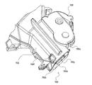
次に、乾燥ユニット700が備える可動ノズル703の具体的な構成の一例について、図5ないし図8に加えて、図10および図11を参照して詳細に説明する。図10および図11は、可動ノズル703の構成の一例を示す斜視図であり、図10が上方からの斜視図、図11が下方からの斜視図である。また、図12および図13は、乾燥ユニット700の変形例を示す斜視図であり、図12は、可動ノズル703が収納位置にある状態を示し、図13は、可動ノズル703が乾燥位置にある状態を示す。
[Configuration of movable nozzle]
Next, an example of a specific configuration of the
可動ノズル703は、図10および図11に示すように、固定ノズル702の形状に対応した略直方体状の筒状となっている。可動ノズル703は、ケース701と同様に難燃性樹脂で成形され、下壁部の内面が底面703a、下壁部の外面が裏面703m、上壁部の外面が天面703c、両側壁部の外面が側面703bとなっており、さらに、前端側は閉塞して前端面703dが形成されている。
As shown in FIGS. 10 and 11, the
このうち、底面703aは、図8の断面図に示すように、右側(本体200に設けられた状態での右側、図中上方)が左側(図中下方)よりも低くなるように傾斜した湾曲面として形成されている。また、図5および図10に示すように、天面703cの前端には、温風を吹き出す吹出開口としての吹出口703eが略台形状に設けられている。また、図6、図7、および図11に示すように、吹出口703eにつながる底面703aの前端部には、内面が曲面として形成されるように曲面部703fとなっている。また、図11に示すように、曲面部703fの右側には排水孔703gが設けられている。
Among these, as shown in the cross-sectional view of FIG. 8, the
このように、底面703aが傾斜した湾曲面となっていることで、可動ノズル703内を流れる温風を、中央部寄り(洗浄ノズルユニット103寄り)に吹き出させることができる。また、曲面部703fを備えることにより、本体200に設けられたときに後端から前端の吹出口703eに向かって送風される温風を、斜め上方に向かって滑らかに吹き出させることが可能となり、局部に当たる温風の風量が減少するおそれを抑制することができる。さらに、前記構成の底面703aおよび曲面部703fを有することで、可動ノズル703内に水性液体が侵入したとしても、当該水性液体は前端の排水孔703g近傍に集まり、当該排水孔703gから容易に排出されることになる。
As described above, since the
ここで、吹出口703eの形状は特に限定されないが、図10に示すように、略台形状であり、当該台形の上底に対応する右側の辺が短く、下底に対応する左側の辺が長くなる形状であると好ましく、さらに、吹出口703eに面する底面703aに、前述した曲面部703fが設けられていることがより好ましい。
Here, the shape of the
便座400に着座した使用者の局部は、本体200の中央部から見て前方となる領域である。それゆえ、前述したとおり、局部を洗浄する機能ユニットである洗浄ノズルユニット103は、本体200の中央部に配置されることが好ましい。一方、乾燥ユニット700も局部に温風を当てる機能ユニットであるので、中央部に配置されることが好ましいが、洗浄ノズルユニット103に比べると、その機能の優先度は相対的に小さい。それゆえ、本実施の形態では、乾燥ユニット700は、洗浄ノズルユニット103の左側(図2ないし図4では向かって右側)に配置される。それゆえ、可動ノズル703から吹き出される温風の風向きは、中央部寄りの右側(図2ないし図5では、向かって左側)に向かう方向に設定されることになる。
The local area of the user seated on the
本実施の形態では、吹出口703eの形状を、図10に示すような台形状とすることで、温風の吹出方向を右側に収束することができる。それゆえ、温風の局部への指向性を高めることができるだけでなく、吹出口703e内で左側から右側に温風が向かう過程で風路幅が狭まるため、温風の速度を上昇することになる。それゆえ、温風の局部に向けて付勢し、その指向性をより高めることができる。さらに、曲面部703fを設けていれば、本体200の上部から前側下部に向かって流出する温風を、曲面部703fで吹出口703eの右上側に方向転換させることができるので、温風の指向性をさらに高めることができる。
In this Embodiment, the blowing direction of warm air can be converged to the right side by making the shape of the
加えて、本実施の形態では、吹出口703eにおいて、前記右側の辺に対応する部位に、前側方切り欠き部703iが設けられているとさらに好ましい。つまり、吹出口703eにおいて、右側(洗浄ノズルユニット103に対向する側)の側面703bの前端となる部位は、その上端が天面703cよりも低くなる前側方切り欠き部703iとなっている。これにより、吹出口703eの右上側となる可動ノズル703の側壁部の上方が取り除かれていることになるので、温風の吹出が側壁部で妨げられることが抑制される。つまり、前側方切り欠き部703iを設けることで、吹出口703e、底面703aおよび曲面部703fにより中央部に向かって収束された温風は、妨げられることなく良好に吹き出すことができる。したがって、前側方切り欠き部703iは、吹出口703eの形状とともに、温風の送風方向を規定する機能を有している。
In addition, in the present embodiment, it is more preferable that a front
しかも、底面703aは、前述したように右側が下向きとなるように傾斜した湾曲面となっていることに加え、前述した曲面部703fが設けられていれば、吹出口703eから吹き出される温風は、右上側への指向性がより一層高められる。したがって、局部へ送風される温風の風量を十分なものとすることができる。なお、図3ないし図5に示されるように、可動ノズル703の突出方向は、本体200の前方に向かって略垂直方向に突出するのではなく、中央部寄りとなるように右側に偏って突出することが好ましい。これにより、前述した可動ノズル703の各構成による作用をさらに高めることができるので、便座400の中央部に対応する使用者の局部に向かって温風を良好に向かわせることができる。
In addition, the
ここで、可動ノズル703の前端部には、乾燥位置にあるときに局部に向かって温風を吹出可能とする吹出口703e(吹出開口)だけでなく、収納位置にあるときに、温風を当該可動ノズル703内から漏出可能とする漏出開口を有している。
Here, at the front end of the
具体的には、可動ノズル703の前端の上面に吹出口703eが設けられているが、当該前端の端面(前端面703d)の上部に、漏出開口としての前端切り欠き部703jが設けられている。つまり、可動ノズル703において、吹出口703eにおける前端面703dの上部は、その上端が天面703cより低くなる前端切り欠き部703jとなっている。この前端切り欠き部703jが設けられていれば、可動ノズル703が収納位置にあるときに、前端切り欠き部703jにより漏出開口が形成される。それゆえ、収納位置の可動ノズル703の内部と外部とを通気可能とすることができる。
Specifically, an
通常、乾燥ユニット700の可動ノズル703は、使用時に乾燥位置まで突出するため、吹出口703eは十分に開口しており、それゆえ、温風が滞ることはない。ところが、非使用時には、可動ノズル703は固定ノズル702内に収納されているので、前端切り欠き部703jが設けられていなければ、吹出口703eが閉塞されてしまう。仮に、ヒータユニット708とファンモータ709が動作して温風の送付が開始されたときに可動ノズル703が収納位置にあれば、当該可動ノズル703内で温風が滞り、内部の温度が過剰に上昇するおそれがある。この場合、ファンモータ709が熱の影響で大きく受ける可能性があり、また、難燃性樹脂で成形されているとはいえ、ケース701(固定ノズル702を含む)および可動ノズル703も熱の影響を大きく受けるおそれがある。
Usually, since the
これに対して、本実施の形態では、前端切り欠き部703jを設けることにより、可動ノズル703が収納位置にあっても、その内外を連通する漏出開口を形成することができる。それゆえ、温風が内部で滞ることが回避される。また、この状態においては、過熱防止器である温度ヒューズ708bおよびサーモスタット708cは動作することがない。これにより、過熱防止器の動作が非常に低い頻度に抑えられるので、乾燥ユニット700の動作が停止する可能性も非常に低くすることができる。
On the other hand, in the present embodiment, by providing the
また、前端切り欠き部703jは、可動ノズル703の前端面703dにおいて、吹出開口である吹出口703eに連続した切り欠き部として設けられている。それゆえ、可動ノズル703の製造時に、吹出口703eとは独立した開口を別途設ける必要がなく、可動ノズル703の構成を簡素化でき、かつ、可動ノズル703の製造過程の煩雑化も回避することができる。
Further, the front
さらに、前述した前側方切り欠き部703iは、温風の送風方向を規定する機能だけでなく、前端切り欠き部703jとともに漏出開口としての機能も発揮することができる。例えば、前側方切り欠き部703iは、可動ノズル703が収納位置にあれば、基本的には、大部分が固定ノズル702により覆われてしまう。しかしながら、図10に示されるように、前側方切り欠き部703iと前端切り欠き部703jとは、天面703cを基準とした切り欠きの程度は異なるものの、互いに連続して一体的な切り欠き部を形成していることになる。したがって、前側方切り欠き部703iも機能は小さいものの漏出開口としての機能を発揮することができる。また、一体的な切り欠き部として構成されることで、可動ノズル703の構成を簡素化することも可能である。
Furthermore, the
加えて、本実施の形態においては、図12および図13に示すように、固定ノズル702の前端右上側のコーナー部に前側方開口部702fを設けることもできる。この構成であれば、図14に示すように、可動ノズル703が収納位置にあっても、前側方開口部702fの位置と前側方切り欠き部703iの位置とが一致するので、有効な開口面積を有する漏出開口を形成することができる。この場合、前端切り欠き部703jは設けなくてもよい。また、図15に示すように、可動ノズル703が乾燥位置まで進出すれば、当該可動ノズル703の側面703bによって前側方開口部702fが閉鎖される。したがって、前側方開口部702fから温風が漏れることがなく、良好に温風を吹き出すことができる。
In addition, in the present embodiment, as shown in FIGS. 12 and 13, a
なお、吹出開口であるとともに温風の送風方向を規定する手段でもある吹出口703eと、漏出開口を構成する前端切り欠き部703jと、温風の送風方向を規定する手段であるとともに漏出開口でもある前側方切り欠き部703iの具体的な構成は特に限定されない。
Note that the
例えば、本実施の形態では、前端切り欠き部703jおよび固定ノズル702の内周面で形成される漏出開口の開口面積は、吹出口703eの開口面積より小さければよく、好ましくは30%以下であればよい。漏出開口の開口面積が30%以下であれば、前端切り欠き部703jが過剰に大きくなることが抑制され、それゆえ、可動ノズル703の前端面703d(前端の壁部)を、温風を中央部寄りに規制できる程度の面積とすることができる。
For example, in the present embodiment, the opening area of the leakage opening formed by the
また、前側方切り欠き部703iは、送風方向を規定する機能を優先することから、図10に示すように、前端切り欠き部703jよりも、天面703cを基準とした切り欠きの程度が大きいものとなっているが、固定ノズル702、可動ノズル703、および吹出口703e等の構成によっては、同等に切り欠かれてもよいし、前端切り欠き部703jの方が大きく切り欠かれてもよい。あるいは、本実施の形態では、切り欠きの程度は異なっていても、前側方切り欠き部703iおよび前端切り欠き部703jが連続して一体的な切り欠き部を構成しているが、前側方切り欠き部703iおよび前端切り欠き部703jは、それぞれ単独の切り欠き部として構成されてもよい。
Further, since the
加えて、本実施の形態では、少なくとも前端切り欠き部703jと固定ノズル702の内周面とで漏出開口が構成されるが、漏出開口の構成はこれに限定されず、可動ノズル703の前端面703dを貫通する形で独立した漏出開口が設けられてもよいし、図14および図15に示す変形例の構成で、前端切り欠き部703jを敢えて設けずに、前側方切り欠き部703iおよび前側方開口部702fのみによって漏出開口を構成してもよい。つまり、本発明においては、漏出開口は、可動ノズル703が固定ノズル702に収納された収納位置にあるときに、漏出開口が温風を可動ノズル703内から漏出可能となるように設けられていれば、その具体的な構成は特に限定されない。
In addition, in the present embodiment, at least the
また、可動ノズル703の左側の側面703bには、略全長に亘ってラック703kが形成されている。このラック703kにはピニオンギア705aが噛合されている。ピニオンギア705aはギア機構705の一部であり、このギア機構705は駆動モータ704とともに、可動ノズル703を進退駆動させる乾燥ノズル駆動機構(進退駆動機構)を構成している。これらは、ケース701におけるラック703kに対向する位置に設けられている。
A
駆動モータ704は正逆回転可能な直流モータであり、駆動モータ704の回転は複数のギアで構成されたギア機構705により減速されてピニオンギア705aに伝達される。そして、ピニオンギア705aはラック703kに噛合されているので、駆動モータ704が回転することにより、可動ノズル703を固定ノズル702内で摺動させることが可能になり、それゆえ、可動ノズル703が進退移動する。
The
また、図10に示すように、ラック703kが設けられている左側の側面703bとは反対側の右側の側面703bには、裏面703mに近い位置に側方リブ703nが設けられていると好ましい。これにより、固定ノズル702内での可動ノズル703の摺動をより滑らかなものとすることができる。
Further, as shown in FIG. 10, it is preferable that
また、図11に示すように、可動ノズル703の裏面703mには、後端より前方に向かって略U字状に切り込んだU字切り込み部703hが設けられている。これにより、可動ノズル703が固定ノズル702に収納された状態(収納位置)において、図6に示すように、平坦面702cの突起部702dに設けられたサーミスタ710が可動ノズル703内に露出することができる。
Further, as shown in FIG. 11, a
ここで、もし可動ノズル703が乾燥位置にある状態で、例えば、局部または臀部に付着した洗浄水が可動ノズル703に落下したり、あるいは、この状態で誤って使用者が放尿をしたり、また清掃の最に可動ノズル703に水をかけてしまった場合、可動ノズル703の内部に侵入した水性液体は曲面部703fに設けられた排水孔703gより便器600内に排水されるが、大量の水性液体が可動ノズル703にかけられた場合には、当該可動ノズル703の奥の方まで浸入するおそれがあり、また、る可動ノズル703の裏面703mが濡れた状態で固定ノズル702内に収納されるおそれがある。
Here, if the
これに対して、可動ノズル703の後端にU字切り込み部703hが設けられていれば、濡れた状態にある可動ノズル703の内部も濡れた裏面703mも、サーミスタ710の上方に位置することが回避される。そのため、可動ノズル703に侵入した水性液体がサーミスタ710に付着するおそれが抑制され、サーミスタ710の温度検知の精度を向上することができる。したがって、制御ユニット204によって、安定した温風温度の実現を図ることができる。
On the other hand, if the
ここで、U字切り込み部703hの具体的構成は特に限定されず、可動ノズル703の後端部において、当該可動ノズル703が固定ノズル702内に収納されたときに、サーミスタ710等の温度検知器が可動ノズル703内に露出できる長さとなるように、前側に切り込まれた切り込み部となっていればよい。したがって、U字状ではなくV字状に切り込まれた構成であってもよいし、他の形状に切り込まれた構成であってもよい。
Here, the specific configuration of the
本実施の形態では、前述した機能ユニットの位置関係で説明したように、乾燥ユニット700は、可能な限り本体200の中央部に近い位置に設けられることが好ましく、それゆえ、本体200内で中央部に設けられる優先度が最も高い洗浄ノズルユニット103に隣接して設けられることが好ましい。したがって、本実施の形態において用いられる可動ノズル703は、前述した台形状の吹出口703e、前側方切り欠き部703i、湾曲して傾斜した底面703a、吹出口703e近傍に設けられる曲面部703fを有していることが特に好ましい。
In the present embodiment, as described in the above-described positional relationship of the functional units, the drying
なお、本実施の形態の構成においては、乾燥ユニット700が洗浄ノズルユニット103の左側に設けられていることから、可動ノズル703は、温風を中央部寄りとなる右側に偏らせる構成を採用しているが、本発明はもちろんこれに限定されず、乾燥ユニット700が洗浄ノズルユニット103の右側に設けられていれば、可動ノズル703は、温風を中央部寄りとなる左側に偏らせる構成を採用すればよい。
In the configuration of the present embodiment, since the
[衛生洗浄装置の動作]
次に、前述した構成の衛生洗浄装置100の動作の一例について、さらに図14を参照して具体的に説明する。図14は、衛生洗浄装置100が乾燥動作を開始するときの可動ノズル703の進出位置に対して、ヒータユニット708への通電率および温風温度の関係を示すタイムチャートである。図14の縦軸は、上から可動ノズル703の(進出)位置、ヒータユニット708への通電率および温風温度であり、横軸は経過時間である。
[Operation of sanitary washing device]
Next, an example of the operation of the
まず、使用者がトイレ室に入室すると、まず人体検知センサ201が人体を検知すれば、制御ユニット204の制御により、便座便蓋開閉ユニットにより便蓋300が自動的に開くとともに、便座400に内蔵される便座ヒータへの通電が開始される。これにより、便座400の暖房が開始され、便座400の温度が設定の温度となるまで昇温する。また、着座センサ202が便座400に着座した使用者を検知すれば、制御ユニット204の制御により、洗浄ノズルユニット103および乾燥ユニット700がリモートコントローラ500で操作可能となる。
First, when a user enters a toilet room, first, when the human
使用者が用便を終了した後に、リモートコントローラ500を操作して洗浄動作を開始させれば、制御ユニット204の制御により、洗浄ノズルユニット103のお尻洗浄ノズル103aが本体200より進出し、洗浄水を噴出させて使用者の局部を洗浄する。その後、使用者がリモートコントローラ500を操作して洗浄を終了させれば、制御ユニット204の制御により、局部の洗浄が終了し、お尻洗浄ノズル103aは本体200内に収納される。
If the user operates the
次に、使用者がリモートコントローラ500を操作して乾燥動作を開始させると、制御ユニット204により、ビデノズル103bの進出が開始され、当該ビデノズル103bによりノズルシャッター203が開けられる。これに引き続いて、乾燥ユニット700のヒータユニット708、ファンモータ709および駆動モータ704に通電が開始される。その後、制御ユニット204は、サーミスタ710で検知された温度データにより、使用時の室温を判断し、当該室温に対応して設定されたヒータユニット708への通電率を決定する。なお、この通電率を設定通電率と称する。
Next, when the user operates the
そして、制御ユニット204は駆動モータ704を駆動し、図14の上段に示すように、可動ノズル703を収納位置から進出させる動作を開始する。これにより、可動ノズル703は、開いた状態にあるノズルシャッター203の下方から便器600の中央に向かって右斜め方向に傾いて進出を開始する。ここで、制御ユニット204は、可動ノズル703の吹出口703eがノズルシャッター203の下方を通過する途中で、ヒータユニット708とファンモータ709への通電を開始する。これによって温風の送風が開始される。
Then, the
本実施の形態では、通電を開始した直後では、前記設定通電率の150%の通電率でヒータユニット708に通電する。例えば、室温が10℃である時の設定通電率が50%に設定されていれば、消費電力は約150Wとなるので、通電の開始直後の消費電力は225Wとなる(図14の中段参照)。それゆえ、制御ユニット204は、図14の下段に示すように、温風の温度を短時間に上昇させる。ファンモータ709への通電率は、乾燥動作が終了するまで100%に維持される。
In the present embodiment, immediately after energization is started, the
このように、本実施の形態では、使用者がリモートコントローラ500(操作器)を操作して乾燥ユニット700(乾燥機構)の動作を開始させたときには、制御ユニット204(制御器)は、進退駆動機構(駆動モータ704およびギア機構705)による可動ノズル703の進出を先に開始させた後に、この可動ノズル703が乾燥位置に達する前に、ファンモータ709(送風機)およびヒータユニット708(加熱器)の動作を開始させる制御を行う。これにより、温風の送風が開始された直後には、可動ノズル703内に滞留している冷たい空気または十分に暖められていない温風(まとめて冷風と称する)は、そのほとんどがノズルシャッター203に遮られる。これにより、冷風はノズルシャッター203により便器600の下方に向かって流れることになり、使用者の局部や臀部に冷風が当たるおそれを回避することができる。
As described above, in the present embodiment, when the user operates the remote controller 500 (operator) to start the operation of the drying unit 700 (drying mechanism), the control unit 204 (controller) is driven forward / backward. After starting the advance of the
また、可動ノズル703の吹出口703eがノズルシャッター203の下から突出すると、吹出口703eから温風が上方に向かって吹き出すことになる。ここで、吹出口703eからの温風は、可動ノズル703の進出移動の途中から使用者の臀部に当たることになる。このとき吹き出される温風の温度は、前述した冷風ではないものの設定温度より低い場合がある。しかしながら、最初に温風が当たる部位は、洗浄動作において洗浄水が付着していない臀部後方であり、また、洗浄水が付着している局部近傍に吹出口703eが面するまでには、温風は設定温度近くまで上昇している。したがって、臀部後方に相対的に低温の温風が当たっても、使用者が冷風感を感じることを回避することができる。
Further, when the
次に、可動ノズル703の進出移動の途中で、サーミスタ710により検知された温風温度が、設定温度である75℃より10℃低い65℃に到達すると、制御ユニット204はヒータユニット708への通電率を、設定通電率である100%まで50%下げて通電を継続する。これにより、温風の温度上昇は、設定温度まで緩やかに到達することになる。それゆえ、温風温度は、が設定温度以上にオーバーシュートしないように制御される。また、サーミスタ710が設定温度である75℃を検知した後は、当該サーミスタ710は、温風温度を常時検知し、制御ユニット204は設定温度の75℃を維持するようにヒータユニット708への通電を制御する。
Next, when the hot air temperature detected by the
なお、本実施の形態においては、ヒータユニット708に対する通電の制御は、通電開始から設定温度に到達するまでは位相制御で行い、設定温度に到達した後は、ON/OFF制御で行っている。
In the present embodiment, energization control for the
次に、可動ノズル703が乾燥位置に到達すると駆動モータ704は停止し、可動ノズル703の吹出口703eから、洗浄により濡れた局部に向かって温風の吹き出しが継続される。ここで、乾燥位置で温風の吹き出しが継続している状態で、使用者がリモートコントローラ500を操作することにより、可動ノズル703を周期的に前後移動させることができる。これにより広い範囲の乾燥が可能となるとともに乾燥効率を高めることができる。また、特定の部位に温風が集中して当たることが回避されるので、人体の一部が局部的に熱くなることを防ぐことができ、快適性を向上することができる。
Next, when the
その後、使用者がリモートコントローラ500で乾燥を終了させる操作をすれば、制御ユニット204は、ファンモータ709およびヒータユニット708への通電を停止するとともに、駆動モータ704を逆方向に回転させる。これにより、温風の送風が停止するともに可動ノズル703は固定ノズル702内へ後退する。その後、可動ノズル703が収納位置に到達すると駆動モータ704は停止する。このとき、可動ノズル703の前端が本体200の前面より後退した時点で、ノズルシャッター203が自重で閉じ、可動ノズル703を隠蔽することになる。
Thereafter, when the user performs an operation to end drying with the
もし、可動ノズル703が、乾燥位置に突出した時点でファンモータ709およびヒータユニット708への通電を開始すれば、通電開始の直後には、乾燥ユニット700の内部に滞留している冷たい空気が使用者の局部または臀部に向かって吹き出される。また、滞留した冷たい空気が放出された後も、温風が所定の温度に到達するためには一定の時間を要する。それゆえ、使用者は、送風開始から一定時間が経過するまで、冷風感(不快感)を覚えることになる。特に、洗浄直後の局部およびその近傍の臀部には洗浄水が多く付着しているので、冷たい空気が当たると、一層強い冷風感を覚えることになる。
If energization to the
これに対して、本実施の形態では、前述した制御を行うことにより、冷たい空気が使用者の局部また臀部に噴出されることを抑制し、送風の開始時点から快適な温度に昇温した温風を、局部または臀部に対して吹き出させている。これにより、使用者は冷風感を覚えることがなく快適に局部等の乾燥を行うことができる。 On the other hand, in the present embodiment, by performing the above-described control, it is possible to suppress the cold air from being blown out to the user's local area or the buttocks, and to raise the temperature to a comfortable temperature from the start of the air blowing. The wind is blown against the local area or the buttocks. Thereby, the user can dry a local part etc. comfortably, without memorizing a cold wind feeling.
ここで、本実施の形態では、制御ユニット204は、ファンモータ709およびヒータユニット708により形成される温風の温度が、予め設定されている乾燥値を超えない温度となるように、ヒータユニット708の出力を調節する制御を行っている。ここで言う乾燥値とは、本実施の形態では設定温度の75℃であり、出力の調節は通電率の調節により行われている。
Here, in the present embodiment, the
また、本実施の形態では、制御ユニット204は、ヒータユニット708の動作の開始直後は、当該ヒータユニット708の出力を、前記乾燥値を維持する標準出力値よりも大きい起動出力値とするとともに、サーミスタ710で検知された温風の温度が、前記乾燥値よりも低い値として設定されている調節値に達したときには、ヒータユニット708の出力を、前記起動出力値から前記標準出力値に低下させる制御を行っている。ここで言う調節値とは設定温度より10℃低い65℃であり、標準出力値とは設定通電率(100%の通電率)により実現される消費電力であり、起動出力値とは150%の通電率により実現される消費電力である。
In the present embodiment, immediately after the start of the operation of the
本発明における制御ユニット204の制御は前記構成に限定されず、それゆえ、温風の温度として設定されている乾燥値および調節値、並びに、ヒータユニット708(厳密にはヒータ線708a)の標準出力値および起動出力値は、前記値に特定されない。また、ヒータユニット708等の加熱器の出力を調節する方法も、通電率の調節に限定されず、公知の他の方法を用いることができる。
The control of the
なお、本実施の形態における制御の具体的な方法は特に限定されない。すなわち、本実施の形態では、制御ユニット204等の制御器が、使用者がリモートコントローラ500等の操作器を操作して乾燥ユニット700等の乾燥機構の動作を開始させたときには、乾燥機構が備える送風機および加熱器を動作させるとともに、温度検知器により検知される温度値の取得し、当該温度値を用いて前記加熱器の出力を調節する制御を行えばよく、また、送風機および加熱器の動作の前に可動ノズル703の進出を開始させる制御を行えばよい。
Note that the specific control method in the present embodiment is not particularly limited. That is, in the present embodiment, when the controller such as the
(実施の形態2)
前記実施の形態1では、制御ユニット204が、可動ノズル703の進出移動を先に開始してからファンモータ709およびヒータユニット708への通電を開始する制御を行っていたが、本実施の形態では、先にファンモータ709およびヒータユニット708への通電を開始してから可動ノズル703の進出移動を開始させる制御を行っている。この構成について、図15を参照して具体的に説明する。図15は、衛生洗浄装置100が乾燥動作を開始するときの可動ノズル703の進出位置に対して、ヒータユニット708への通電率および温風温度の関係を示すタイムチャートであり、縦軸および横軸で示される単位は図14と同様である。
(Embodiment 2)
In the first embodiment, the
本実施の形態における衛生洗浄装置の構成は、前記実施の形態1と同様であるので、その具体的な説明は省略する。本実施の形態が前記実施の形態1と異なる点は、乾燥動作において、駆動モータ704、ヒータユニット708、およびファンモータ709の制御シーケンスが異なる点である。
Since the configuration of the sanitary washing apparatus in the present embodiment is the same as that in the first embodiment, a specific description thereof will be omitted. The present embodiment is different from the first embodiment in that the control sequence of the
本実施の形態においては、リモートコントローラ500により乾燥動作の開始が操作されると、制御ユニット204は、駆動モータ704を動作させずに、ヒータユニット708およびファンモータ709への通電を開始する、ヒータユニット708への通電は実施の形態1と同様に、サーミスタ710で検知された温度が65℃(調節値)に到達するまでは、設定通電率の150%の通電率(起動出力値を実現する通電率)で通電し、その後通電率を設定通電率(標準出力値を実現する通電率)に落として通電する。
In the present embodiment, when the start of the drying operation is operated by the
このとき、可動ノズル703に送り込まれた低温の温風または冷風は、可動ノズル703の前端に設けられ前端切り欠き部703jおよび固定ノズル702の内周面により形成される漏出開口より前方に向かって噴出される。あるいは、固定ノズル702に前側方開口部702fが設けられていれば、前記低温の温風または冷風は、当該前側方開口部702fおよび前側方切り欠き部703iにより形成される漏出開口により、側方に向かって噴出される。
At this time, the low temperature warm air or cold air sent to the
さらに、前記漏出開口から噴出した低温の温風または冷風は、ノズルシャッター203に当たって便器600の下方に向かって流れる。それゆえ、可動ノズル703内に滞留した冷風や、十分に加熱されていない低温の温風は、使用者の臀部に当たることが回避される。また、前記漏出開口は吹出口703eに比べ開口面積が小さいため、収納位置にある可動ノズル703内で空気が緩やかに滞留する。それゆえ、可動ノズル703内の空気を短時間に昇温することができる。
Further, the low-temperature hot air or cold air ejected from the leak opening hits the
サーミスタ710により検知した温風の温度が、設定温度である75℃(乾燥値)に到達すると、制御ユニット204は、駆動モータ704の動作を開始し、可動ノズル703を収納位置から乾燥位置へ進出させる。乾燥位置に到達した後の制御シーケンスは実施の形態1と同様であるので、その説明は省略する。
When the temperature of the hot air detected by the
このように、本実施の形態においては、使用者がリモートコントローラ500等の操作器を操作して乾燥ユニット700等の乾燥機構の動作を開始させたときには、制御ユニット204等の制御器は、ファンモータ709等の送風機、および、ヒータユニット708(厳密にはヒータ線708a)等の加熱器の動作を先に開始させてから、温風の温度が乾燥値に達したことがサーミスタ710等の温度検知器により検知されれば、進退駆動機構による可動ノズル703の進出を開始させる制御を行う。
As described above, in the present embodiment, when the user operates the operation device such as the
これにより、可動ノズル703の進出動作が開始された時点では、温風の温度はすでに設定温度(乾燥値)まで上昇しているので、進出動作の過程で、使用者の臀部に当たる温風はすでに設定温度に到達している。それゆえ、使用者は冷風感を覚えることはなく、高いレベルの快適性を確保することができる。
Thereby, when the advance operation of the
以上のように、本発明に係る衛生洗浄装置の好ましい一例としては、便器上に載置する本体と、前記本体に回動自在に枢支した便座と、前記便座に着座した人体局部に向けて洗浄水を噴出する洗浄手段(洗浄機構)と、前記便座に着座した人体局部に向けて温風を噴出する乾燥手段(乾燥機構)を含み、前記乾燥手段は、送風機と、加熱手段(加熱器)と、温度検知手段(温度検知器)と、温度過昇防止手段(過熱防止器)と、固定ノズルと、可動ノズルを含み、前記送風機は前記加熱手段の上流に設置し、前記温度過昇防止手段は前記送風機と前記加熱手段の間に設置し、前記温度検知手段は前記加熱手段の下流に設置し、前記可動ノズルは、後端は開口し、前端は閉塞する前端面を備えた筒状とし、前端部の天面に上方に開口する噴出口(吹出開口)を備え、前記前端面の一部を開口した開口部(漏出開口)を備え、前記可動ノズルは前記固定ノズルに挿通して前記本体より進退可能とし、前記固定ノズルに前記可動ノズルを収容した収納状態では、前記開口部を介して少量の温風を外部に噴出することを可能とし、前記固定ノズルより前記可動ノズルが進出した乾燥状態では、前記便座に着座した人体局部に向けて前記噴出口より温風を噴出する構成が挙げられる。 As described above, as a preferable example of the sanitary washing device according to the present invention, a main body placed on a toilet bowl, a toilet seat pivotally supported on the main body, and a human body seated on the toilet seat. It includes a cleaning means (cleaning mechanism) for ejecting washing water and a drying means (drying mechanism) for ejecting warm air toward a human body seated on the toilet seat. The drying means includes a blower, a heating means (heater) ), Temperature detection means (temperature detector), overtemperature prevention means (overheat prevention device), fixed nozzle, and movable nozzle, and the blower is installed upstream of the heating means, and the overtemperature rise The prevention means is installed between the blower and the heating means, the temperature detection means is installed downstream of the heating means, and the movable nozzle has a front end face that is open at the rear end and closed at the front end. And a jet outlet that opens upward on the top surface of the front end A blowout opening), and an opening (leakage opening) in which a part of the front end surface is opened. The movable nozzle is inserted into the fixed nozzle so as to advance and retreat from the main body. The movable nozzle is connected to the fixed nozzle. In the housed storage state, a small amount of warm air can be ejected to the outside through the opening, and in the dry state in which the movable nozzle has advanced from the fixed nozzle, toward the human body part seated on the toilet seat The structure which ejects warm air from the said jet nozzle is mentioned.
前記構成によれば、固定ノズルに可動ノズルを収容した収納状態において、送風機と加熱手段が稼動して温風が送風された場合でも、開口部を介して温風は外部に噴出させることができるので、温風が温風ノズル内に滞らない構成とすることができる。これにより、乾燥手段内部の過剰な温度上昇を抑制することができ、特に、空気の流れを維持できることにより、送風機と加熱手段の間に設置した温度過昇防止手段の温度上昇を効果的に抑制することができる。それゆえ、温度過昇防止手段の必要以上の作動を抑制することができ、長期間安定して使用できる衛生洗浄装置を提供することができる。つまり、耐久性と信頼性とが高い乾燥手段を備えた衛生洗浄装置を得ることができる。 According to the above configuration, even when the blower and the heating means are operated and the warm air is blown in the housed state where the movable nozzle is accommodated in the fixed nozzle, the warm air can be ejected to the outside through the opening. Therefore, it can be set as the structure by which a warm air does not stagnate in a warm air nozzle. As a result, excessive temperature rise inside the drying means can be suppressed, and in particular, by maintaining the air flow, the temperature rise of the overheat prevention means installed between the blower and the heating means can be effectively suppressed. can do. Therefore, it is possible to provide a sanitary washing device that can suppress the excessive operation of the temperature rise prevention means and that can be used stably for a long period of time. That is, it is possible to obtain a sanitary washing apparatus including a drying means with high durability and reliability.
前記構成においては、前記温度過昇防止手段は、復帰型のサーモスタットと、非復帰型の温度ヒューズで構成されていると好ましく、前記温度ヒューズを前記サーモスタットより前記送風機に近い上流側に設けられているとより好ましい。 In the above configuration, it is preferable that the overheat prevention means is composed of a return thermostat and a non-reset temperature fuse, and the temperature fuse is provided on the upstream side of the thermostat closer to the blower. It is more preferable.
前記構成によれば、二重の温度過昇防止手段を備えたこととなるので、信頼性をより向上することができる。さらに、第1のステップとして復帰型のサーモスタットを作動させ、第2ステップとして非復帰型の温度ヒューズを作動させるように設定することにより、非復帰型の温度ヒューズの作動を抑制することができるので、必要以上のメンテナンスや修理を抑制することができる。加えて、前記温度ヒューズが前記送風機に近い位置に設けられれば、非復帰型の温度ヒューズの温度上昇は送風機が正常に作動している限り、サーモスタットの温度より低く保たれる。それゆえ、温度ヒューズの作動をより確実に抑制することができる。 According to the said structure, since the double overheat prevention means was provided, reliability can be improved more. Furthermore, by operating the reset thermostat as the first step and operating the non-reset thermal fuse as the second step, the operation of the non-reset thermal fuse can be suppressed. Unnecessary maintenance and repair can be suppressed. In addition, if the temperature fuse is provided at a position close to the blower, the temperature rise of the non-returnable temperature fuse is kept lower than the temperature of the thermostat as long as the blower is operating normally. Therefore, the operation of the thermal fuse can be suppressed more reliably.
また、本発明に係る衛生洗浄装置の他の好ましい一例としては、便器上に載置する本体と、前記本体に回動自在に枢支した便座と、前記便座に着座した人体局部に向けて洗浄水を噴出する洗浄手段と、前記便座に着座した人体局部に向けて温風を噴出する乾燥手段と、前記洗浄手段と乾燥手段を制御する制御手段(制御器)と、前記制御手段を操作する操作手段(操作器)を含み、前記乾燥手段は、送風機と、加熱手段と、温度検知手段と、固定ノズルと、可動ノズルと、前記可動ノズルを進退する駆動手段(進退駆動機構)を含み、前記可動ノズルは前端部に噴出口を備え、前記固定ノズルに挿通して収納位置と乾燥位置とを進退可能とし、前記操作手段で乾燥の操作をした場合、前記制御手段は、前記駆動手段の駆動を開始し、前記可動ノズルが前記乾燥位置に到達する以前に、前記送風機と前記加熱手段への通電を開始する構成が挙げられる。 In addition, as another preferable example of the sanitary washing device according to the present invention, a main body placed on a toilet bowl, a toilet seat pivotally supported on the main body, and a human body seated on the toilet seat are washed toward A cleaning means for ejecting water, a drying means for ejecting warm air toward a human body seated on the toilet seat, a control means (controller) for controlling the cleaning means and the drying means, and operating the control means The drying means includes an air blower, a heating means, a temperature detection means, a fixed nozzle, a movable nozzle, and a drive means (advance / retreat drive mechanism) for moving the movable nozzle back and forth. The movable nozzle is provided with a spout at the front end, and is inserted into the fixed nozzle so that the storage position and the drying position can be advanced and retracted.When the operation means performs a drying operation, the control means Start driving and move Before nozzle reaches the drying position, configuration and the like to start the energization of the heating means and the blower.
前記構成によれば、可動ノズルが乾燥位置に到達する前から送風機と加熱手段への通電が開始されるため、可動ノズルが乾燥位置に到達した時点では、温風の温度は昇温しており、使用者は不快を感じることがない。つまり、噴出開始時から快適な温度に昇温した温風を噴出することができるので、使用者は冷感を感じることがなく、それゆえ、使用者に不快感を与えることがない。その結果、乾燥開始直後から快適な温風が供給される快適な乾燥手段を備えることができる。 According to the above configuration, since the energization to the blower and the heating means is started before the movable nozzle reaches the drying position, the temperature of the hot air is increased when the movable nozzle reaches the drying position. The user does not feel uncomfortable. That is, since warm air heated to a comfortable temperature from the start of ejection can be ejected, the user does not feel cold and therefore does not feel uncomfortable for the user. As a result, it is possible to provide a comfortable drying means for supplying comfortable warm air immediately after the start of drying.
あるいは、他の一例としては、便器上に載置する本体と、前記本体に回動自在に枢支した便座と、前記便座に着座した人体局部に向けて洗浄水を噴出する洗浄手段と、前記便座に着座した人体局部に向けて温風を噴出する乾燥手段と、前記洗浄手段と乾燥手段を制御する制御手段と、前記制御手段を操作する操作手段を含み、前記乾燥手段は、送風機と、加熱手段と、温度検知手段と、固定ノズルと、可動ノズルと、前記可動ノズルを進退する駆動手段を含み、前記可動ノズルは前端部に噴出口を備え、前記固定ノズルに挿通して収納位置と乾燥位置とを進退可能とし、前記操作手段で乾燥の操作をした場合、前記制御手段は、前記送風機と前記加熱手段への通電を開始し、前記温度検知手段が設定温度(乾燥値)を検知したら、前記駆動手段の駆動を開始する構成を挙げることもできる。 Alternatively, as another example, a main body placed on a toilet bowl, a toilet seat pivotally supported on the main body, a cleaning means for ejecting cleaning water toward a human body part seated on the toilet seat, A drying unit that ejects warm air toward a local body seated on a toilet seat, a control unit that controls the cleaning unit and the drying unit, and an operation unit that operates the control unit, the drying unit including a blower, A heating means, a temperature detection means, a fixed nozzle, a movable nozzle, and a drive means for moving the movable nozzle forward and backward, the movable nozzle having a jet port at a front end, and inserted into the fixed nozzle to be in a storage position. When the drying position can be moved forward and backward, and the drying operation is performed by the operation means, the control means starts energization to the blower and the heating means, and the temperature detection means detects a set temperature (dry value). Once you have said driving hand Mention may also be a configuration to start the drive.
前記構成によれば、温風温度が乾燥に最適な設定温度に昇温してから、可動ノズルの進出動作を開始することとなる。そのため、人体局部や臀部に冷風が当たることが実質的に皆無となり、使用者に不快感を与えることがない。その結果、乾燥開始直後から快適な温風が供給される快適な乾燥手段を備えることができる。 According to the above configuration, the advance operation of the movable nozzle is started after the warm air temperature is raised to the set temperature optimum for drying. Therefore, there is virtually no cold air hitting the human body part or the buttocks, and the user is not uncomfortable. As a result, it is possible to provide a comfortable drying means for supplying comfortable warm air immediately after the start of drying.
前記構成においては、前記加熱手段への通電は、通電開始直後は大きい通電容量で通電し、前記温度検知手段が設定温度より低い所定温度(調節値)を検知したら、通電容量を減少する構成であると好ましい。 In the above configuration, the heating means is energized with a large energization capacity immediately after the start of energization, and the energization capacity is decreased when the temperature detection means detects a predetermined temperature (adjustment value) lower than a set temperature. Preferably there is.
前記構成によれば、最初は高い昇温速度で昇温し、設定温度に近づくと昇温速度を低下させて設定温度をオーバーシュートすることを抑制することができる。それゆえ、短時間で昇温できるとともに正確な温度設定が可能となる。 According to the said structure, it heats up at a high temperature increase rate initially, and when it approaches set temperature, it can suppress that a temperature increase rate falls and overshoots set temperature. Therefore, the temperature can be raised in a short time and the temperature can be accurately set.
また、本発明に係る衛生洗浄装置のさらに他の好ましい一例としては、便器上に載置する本体と、前記本体に回動自在に枢支した便座と、前記便座に着座した人体局部に向けて洗浄水を噴出する洗浄手段と、前記便座に着座した人体局部に向けて温風を噴出する乾燥手段を含み、前記乾燥手段は、送風機と、加熱手段と、温度検知手段と、固定ノズルと、前端に噴出口を備えた可動ノズルを含み、前記可動ノズルは前記固定ノズルに挿通して前記本体より進退し、前記便座に着座した人体局部に向けて前記噴出口より温風を噴出し、前記固定ノズルの後端は前記本体の内部に位置し、前記固定ノズルの前端は前記本体の前面下部に位置し、前記固定ノズルの底部には後方より前方が低い傾斜部(傾斜面)を備えるとともに、前記傾斜部の後端に連接して前記傾斜部より緩やかな傾斜の平坦部(平坦面)を備え、前記平坦部に前記温度検知手段を設置し、前記可動ノズルが後退した状態で、前記可動ノズルの底部が前記温度検知手段を覆わない構成が挙げられる。 Further, as another preferred example of the sanitary washing device according to the present invention, a main body placed on a toilet bowl, a toilet seat pivotally supported on the main body, and a human body seated on the toilet seat A cleaning means for ejecting washing water; and a drying means for ejecting warm air toward a human body part seated on the toilet seat, wherein the drying means includes a blower, a heating means, a temperature detection means, a fixed nozzle, Including a movable nozzle provided with a spout at the front end, the movable nozzle is inserted into the fixed nozzle, advances and retreats from the main body, and blows warm air from the spout toward the human body part seated on the toilet seat, The rear end of the fixed nozzle is located inside the main body, the front end of the fixed nozzle is located at the lower part of the front surface of the main body, and the bottom of the fixed nozzle is provided with an inclined portion (inclined surface) lower in the front than the rear. The rear end of the inclined part A flat portion (flat surface) that is connected and has a gentler slope than the inclined portion is provided, the temperature detecting means is installed on the flat portion, and the bottom of the movable nozzle is the temperature detection in a state where the movable nozzle is retracted. The structure which does not cover a means is mentioned.
前記構成によれば、温度検知手段は固定ノズルの傾斜部の後端の最高位置となる平坦部に設置したため、可動ノズルが進出した状態では、噴出孔から距離的に離れ、しかも高低差も大きいため、清掃時の水が到達しにくい構成であるとともに、例えば清掃時の水が付着した可動ノズルを固定ノズル内に後退させた場合でも、温度検知手段を覆わないため、可動ノズルの底部に付着した水が温度検知手段に落下したり付着したりすることがなく、温度検知手段を常に乾燥した状態で維持できるため、温風の温度の安定を図ることができる。これにより、乾燥手段の温風温度をコントロールする温度検知手段に、水が付着することにより発生する検知誤差を抑制し、温風の温度が安定した快適な乾燥手段を備える衛生洗浄装置を得ることができる。 According to the above configuration, since the temperature detecting means is installed in the flat portion which is the highest position of the rear end of the inclined portion of the fixed nozzle, when the movable nozzle has advanced, it is separated from the ejection hole and has a large height difference. Therefore, it is difficult to reach the water at the time of cleaning, and for example, even when the movable nozzle to which the water at the time of cleaning adheres is retracted into the fixed nozzle, it does not cover the temperature detection means, so it adheres to the bottom of the movable nozzle. Therefore, the temperature detection means can be kept in a dry state without falling or adhering to the temperature detection means, so that the temperature of the hot air can be stabilized. Thus, a sanitary washing device having a comfortable drying means with a stable temperature of hot air can be obtained by suppressing detection errors caused by water adhering to the temperature detecting means for controlling the hot air temperature of the drying means. Can do.
前記構成においては、前記可動ノズルは筒状とし、底部後端より前方に切り込んだ切り欠き部を設け、前記可動ノズルを後退した状態で、前記温度検知手段は前記切り欠き部の内方に配置される構成であると好ましい。これにより、温度検知手段は切り欠き部の内方に配置されるため、可動ノズルの底部に付着した水が温度検知手段に付着することがなく、しかも、可動ノズルの全長を切り欠き部の分長くできるため、進出距離を長くできるとともに進退動作の安定を図ることができる。 In the above configuration, the movable nozzle has a cylindrical shape, is provided with a cutout portion cut forward from the rear end of the bottom, and the temperature detection means is disposed inside the cutout portion in a state in which the movable nozzle is retracted. It is preferable that it is the structure made. As a result, since the temperature detecting means is disposed inward of the notch, the water adhering to the bottom of the movable nozzle does not adhere to the temperature detecting means, and the entire length of the movable nozzle is divided by the notch. Since it can be lengthened, the advancing distance can be increased and the advance / retreat operation can be stabilized.
また、前記構成においては、前記平坦部に上方に突起した突起部を設け、前記温度検知手段を前記突起部に設置した構成であると好ましい。これにより、たとえ平坦部に大量の水が落下した場合でも、温度検知手段に水が付着することを防止することができ、より温度検知の安定化を図ることができる。 Moreover, in the said structure, it is preferable in the structure which provided the projection part which protruded upwards in the said flat part, and installed the said temperature detection means in the said projection part. Thereby, even when a large amount of water falls on the flat portion, it is possible to prevent water from adhering to the temperature detecting means, and it is possible to further stabilize the temperature detection.
あるいは、前記構成においては、前記固定ノズルの傾斜部と前記可動ノズルの底部との間に間隙を形成し、前記間隙は傾斜部の後端から前端まで連通し、前記間隙の前端および後端は開放した構成とし、前記間隙を介して乾燥手段内に進入した水を排水可能な構成であると好ましい。これにより、平坦部に比較的大量の水が浸入した場合でも、そのほとんどは間隙を介してノズル外に排出されるため、温度検知手段に水が付着することをより確実に防止することができる。 Alternatively, in the configuration, a gap is formed between the inclined portion of the fixed nozzle and the bottom portion of the movable nozzle, the gap communicates from the rear end to the front end of the inclined portion, and the front end and the rear end of the gap are It is preferable to have a configuration in which the water that has entered the drying means through the gap can be drained. Accordingly, even when a relatively large amount of water enters the flat portion, most of the water is discharged out of the nozzle through the gap, so that it is possible to more reliably prevent water from adhering to the temperature detecting means. .
ここで、前述したように、本発明は、衛生洗浄装置において、過熱防止器の必要以上の作動を抑制することが可能となり、さらには、使用者に冷風が当たり不快を感じることを抑制することが可能となりあるいは、温風の温度をコントロールするサーミスタに水がかかる心配が低減され、サーミスタの検知温度の誤差の発生をなくす事が可能となる。したがって、本発明の技術思想は、衛生洗浄装置だけでなく、例えば、温風を発生させたり使用したりする他の家電機器にも適用可能であり、あるいは、温水を使用する給湯器等の他の民生機器にも適用可能である。 Here, as described above, in the sanitary washing apparatus, the present invention can suppress the operation of the overheat protector more than necessary, and further suppress the user from feeling uncomfortable with the cold air. Or, it is possible to reduce the concern that the thermistor that controls the temperature of the hot air is covered with water, and to eliminate the error in the temperature detection of the thermistor. Therefore, the technical idea of the present invention can be applied not only to a sanitary washing apparatus, but also to other home appliances that generate or use hot air, or other hot water heaters that use hot water, etc. It can also be applied to other consumer devices.
なお、本発明は前述した各実施の形態の記載に限定されるものではなく、特許請求の範囲に示した範囲内で種々の変更が可能であり、異なる実施の形態や複数の変形例にそれぞれ開示された技術的手段を適宜組み合わせて得られる実施の形態についても本発明の技術的範囲に含まれる。 The present invention is not limited to the description of each of the embodiments described above, and various modifications can be made within the scope of the claims, and different embodiments and a plurality of modifications can be used. Embodiments obtained by appropriately combining the disclosed technical means are also included in the technical scope of the present invention.
本発明は、衛生洗浄装置、便座装置、トイレ装置等の分野に広く好適に用いることができることに加え、温風を発生させたり使用したりする同様の家電機器または民生機器の分野に広く好適に用いることができる。 The present invention can be widely used suitably in the fields of sanitary washing devices, toilet seat devices, toilet devices, etc., and is also widely suitable in the field of similar home appliances or consumer devices that generate and use hot air. Can be used.
100 衛生洗浄装置
101 給水ユニット
102 熱交換器
103 洗浄ノズルユニット(洗浄機構)
200 本体
204 制御ユニット(制御器)
400 便座
500 リモートコントローラ(操作器)
600 便器
700 乾燥ユニット(乾燥機構)
702 固定ノズル
702a 傾斜面
702c 平坦面
702d 突起部
703 可動ノズル
703a 底面
703d 前端面
703e 吹出口(吹出開口)
703h U字切り込み部(切り込み部)
703i 前側方切り欠き部(漏出開口)
703j 前端切り欠き部(漏出開口)
704 駆動モータ(進退駆動機構)
705 ギア機構(進退駆動機構)
708a ヒータ線(加熱器)
708d 温度ヒューズ(過熱防止器)
708c サーモスタット(過熱防止器)
709 ファンモータ(送風機)
710 サーミスタ(温度検知器)
100
200
400
600
702
703h U-shaped notch (notch)
703i Front side cutout (leakage opening)
703j Front end notch (leakage opening)
704 Drive motor (advance / retreat drive mechanism)
705 Gear mechanism (advance / retreat drive mechanism)
708a Heater wire (heater)
708d Thermal fuse (overheat protector)
708c Thermostat (overheat protector)
709 Fan motor
710 thermistor (temperature detector)
Claims (9)
当該便座を回動自在に支持する本体と、
当該本体内に設けられ、前記便座に着座した使用者の局部に向けて洗浄水を噴出可能とする洗浄機構と、
前記本体内に設けられ、前記局部に向けて温風を吹出可能とする乾燥機構と、
を備え、
前記乾燥機構は、
送風機、加熱器、当該乾燥機構の温度の過剰な上昇を防止する過熱防止器、および、温度検知器を備え、
前記温風の流れる方向を基準として上流側から、前記送風機、前記過熱防止器、前記加熱器、および前記温度検知器の順となる位置関係で設けているとともに、
前記本体内から外部へ進出可能に設けられる可動ノズルと、前記本体内に位置し、前記可動ノズルを内部に収納可能とする固定ノズルと、を備え、
さらに、前記可動ノズルの前端部には、
前記固定ノズルから進出して当該前端部が前記局部に面する乾燥位置まで達したときに、当該局部に向かって前記温風を吹出可能とする吹出開口が設けられ、
前記固定ノズルは、その前端部が下方となるように傾斜した状態で前記本体内に設けられ、
前記温度検知器は、前記固定ノズルの後端部において、前記固定ノズル内に前記可動ノズルが収納された状態で前記可動ノズルの内部に露出する位置に設けられていることを特徴とする、衛生洗浄装置。 Toilet seat and
A main body that rotatably supports the toilet seat;
A cleaning mechanism provided in the main body, and capable of ejecting cleaning water toward a local part of a user seated on the toilet seat;
A drying mechanism provided in the main body and capable of blowing warm air toward the local part;
With
The drying mechanism is
A blower, a heater, an overheat preventer that prevents an excessive increase in the temperature of the drying mechanism, and a temperature detector,
From the upstream side with respect to the direction in which the hot air flows, from the upstream side, provided in the positional relationship in the order of the blower, the overheat protector, the heater, and the temperature detector,
A movable nozzle provided to be able to advance from the inside of the main body to the outside, and a fixed nozzle that is located in the main body and can store the movable nozzle inside,
Furthermore, at the front end of the movable nozzle,
When the fixed nozzle is advanced and reaches the dry position where the front end part faces the local part, a blowout opening is provided that allows the warm air to be blown toward the local part,
The fixed nozzle is provided in the main body in an inclined state so that a front end portion thereof is downward,
The temperature detector is provided at a rear end portion of the fixed nozzle at a position exposed inside the movable nozzle in a state where the movable nozzle is accommodated in the fixed nozzle. Cleaning device.
当該平坦面に、前記温度検知器が設けられていることを特徴とする、請求項1に記載の衛生洗浄装置。 The lower inner surface of the rear end portion of the fixed nozzle is a flat surface having an inclination angle smaller than the inclination angle of the fixed nozzle itself,
The sanitary washing device according to claim 1, wherein the temperature detector is provided on the flat surface.
Priority Applications (1)
| Application Number | Priority Date | Filing Date | Title |
|---|---|---|---|
| JP2010040592A JP5153807B2 (en) | 2009-02-26 | 2010-02-25 | Sanitary washing device with drying mechanism |
Applications Claiming Priority (7)
| Application Number | Priority Date | Filing Date | Title |
|---|---|---|---|
| JP2009043359 | 2009-02-26 | ||
| JP2009043360 | 2009-02-26 | ||
| JP2009043361 | 2009-02-26 | ||
| JP2009043361 | 2009-02-26 | ||
| JP2009043359 | 2009-02-26 | ||
| JP2009043360 | 2009-02-26 | ||
| JP2010040592A JP5153807B2 (en) | 2009-02-26 | 2010-02-25 | Sanitary washing device with drying mechanism |
Related Child Applications (1)
| Application Number | Title | Priority Date | Filing Date |
|---|---|---|---|
| JP2012168312A Division JP5192599B2 (en) | 2009-02-26 | 2012-07-30 | Sanitary washing device with drying mechanism |
Publications (3)
| Publication Number | Publication Date |
|---|---|
| JP2010222964A JP2010222964A (en) | 2010-10-07 |
| JP2010222964A5 JP2010222964A5 (en) | 2012-09-13 |
| JP5153807B2 true JP5153807B2 (en) | 2013-02-27 |
Family
ID=42665327
Family Applications (2)
| Application Number | Title | Priority Date | Filing Date |
|---|---|---|---|
| JP2010040592A Active JP5153807B2 (en) | 2009-02-26 | 2010-02-25 | Sanitary washing device with drying mechanism |
| JP2012168312A Active JP5192599B2 (en) | 2009-02-26 | 2012-07-30 | Sanitary washing device with drying mechanism |
Family Applications After (1)
| Application Number | Title | Priority Date | Filing Date |
|---|---|---|---|
| JP2012168312A Active JP5192599B2 (en) | 2009-02-26 | 2012-07-30 | Sanitary washing device with drying mechanism |
Country Status (4)
| Country | Link |
|---|---|
| JP (2) | JP5153807B2 (en) |
| KR (1) | KR101227748B1 (en) |
| CN (1) | CN101970767B (en) |
| WO (1) | WO2010098114A1 (en) |
Families Citing this family (13)
| Publication number | Priority date | Publication date | Assignee | Title |
|---|---|---|---|---|
| CN102747769B (en) * | 2012-05-22 | 2015-02-04 | 李飞宇 | Drying device of water closet (WC) pan |
| JP6074844B2 (en) * | 2012-12-13 | 2017-02-08 | パナソニックIpマネジメント株式会社 | Toilet device |
| CN104631592B (en) * | 2013-11-15 | 2017-03-29 | 上海科勒电子科技有限公司 | A kind of dehumidifying method of toilet electric appliance box |
| JP6571457B2 (en) | 2015-08-31 | 2019-09-04 | 株式会社Lixil | Toilet device |
| TWI555495B (en) * | 2015-11-13 | 2016-11-01 | Shao-Yu Peng | Computer toilet seat drying structure |
| CN107051633B (en) * | 2017-04-14 | 2018-12-25 | 玉环市旭日五金厂 | A kind of cultural spreading company waste newspaper efficient process equipment |
| DE112019001732T5 (en) * | 2018-03-30 | 2021-01-14 | Lixil Corporation | Toilet seat device and toilet device |
| KR102223013B1 (en) * | 2018-05-09 | 2021-03-05 | 코웨이 주식회사 | Drying apparatus with rotary drying nozzle and bidet device with drying apparatus |
| CN109091056A (en) * | 2018-06-20 | 2018-12-28 | 上海科勒电子科技有限公司 | Squatting pan warm wind apparatus, control method and toilet |
| KR102326447B1 (en) * | 2019-03-15 | 2021-11-15 | 코웨이 주식회사 | Bidet body with flat bottom surface |
| CN110387931B (en) * | 2019-07-15 | 2021-04-20 | 厦门瑞尔特卫浴科技股份有限公司 | Flexible cleaning system and intelligent toilet stool |
| JP7394604B2 (en) * | 2019-11-29 | 2023-12-08 | 株式会社Lixil | toilet seat device |
| JP7394633B2 (en) | 2020-01-16 | 2023-12-08 | 株式会社Lixil | toilet seat device |
Family Cites Families (11)
| Publication number | Priority date | Publication date | Assignee | Title |
|---|---|---|---|---|
| JPH0211502Y2 (en) * | 1984-11-26 | 1990-03-23 | ||
| JPH0533587Y2 (en) * | 1986-10-22 | 1993-08-26 | ||
| JPH0384133A (en) * | 1989-08-28 | 1991-04-09 | Matsushita Electric Works Ltd | Hot-water washing toilet seat |
| KR970070362A (en) * | 1996-04-02 | 1997-11-07 | 김광호 | Drying device for hot water scrubber |
| JP3237551B2 (en) * | 1996-12-16 | 2001-12-10 | 株式会社イナックス | Drying equipment for sanitary washing equipment |
| JPH1161946A (en) * | 1997-08-22 | 1999-03-05 | Matsushita Electric Ind Co Ltd | Toilet device |
| JPH11324074A (en) * | 1998-05-18 | 1999-11-26 | Matsushita Electric Ind Co Ltd | Toilet device |
| JP2002186570A (en) * | 2000-12-22 | 2002-07-02 | Toto Ltd | Control method for heated toilet seat |
| KR200310462Y1 (en) * | 2002-12-04 | 2003-04-18 | 웅진코웨이개발 주식회사 | A drying apparaus for bidet using multiple air-outlet |
| JP2007205141A (en) * | 2006-02-06 | 2007-08-16 | Aisin Seiki Co Ltd | Private part warm air dryer |
| JP4905205B2 (en) * | 2007-03-23 | 2012-03-28 | パナソニック株式会社 | Nozzle device and sanitary washing device using it |
-
2010
- 2010-02-25 WO PCT/JP2010/001291 patent/WO2010098114A1/en active Application Filing
- 2010-02-25 KR KR1020107020581A patent/KR101227748B1/en active IP Right Grant
- 2010-02-25 CN CN2010800012314A patent/CN101970767B/en active Active
- 2010-02-25 JP JP2010040592A patent/JP5153807B2/en active Active
-
2012
- 2012-07-30 JP JP2012168312A patent/JP5192599B2/en active Active
Also Published As
| Publication number | Publication date |
|---|---|
| JP5192599B2 (en) | 2013-05-08 |
| KR20100125321A (en) | 2010-11-30 |
| CN101970767A (en) | 2011-02-09 |
| JP2012233402A (en) | 2012-11-29 |
| JP2010222964A (en) | 2010-10-07 |
| WO2010098114A1 (en) | 2010-09-02 |
| KR101227748B1 (en) | 2013-01-29 |
| CN101970767B (en) | 2012-08-08 |
Similar Documents
| Publication | Publication Date | Title |
|---|---|---|
| JP5153807B2 (en) | Sanitary washing device with drying mechanism | |
| WO2007114298A1 (en) | Sanitary cleaner and toilet device | |
| CN107949677A (en) | Apparatus for closet | |
| JP2010227360A (en) | Toilet seat heating device | |
| JP4942399B2 (en) | Sanitary washing device and toilet device | |
| JP4882858B2 (en) | Sanitary washing device | |
| JP5597996B2 (en) | Sanitary washing device | |
| JP5446747B2 (en) | Sanitary washing device | |
| JP2001311200A (en) | Sanitary washing device | |
| JP5628594B2 (en) | Sanitary washing device | |
| JP5299228B2 (en) | Sanitary washing device | |
| JP7390221B2 (en) | toilet device | |
| US20210017753A1 (en) | Toilet seat assembly | |
| JP2006219926A (en) | Toilet device | |
| JP3894456B1 (en) | Toilet equipment | |
| JP2004116151A (en) | Sanitary flushing device | |
| JP7102841B2 (en) | Toilet seat device | |
| JP2002201698A (en) | Sanitary washing apparatus | |
| KR890004906Y1 (en) | Irrigator for the anus | |
| JPS6241831A (en) | Sanitary washing and drying apparatus | |
| JP2006274568A (en) | Sanitary washing toilet seat | |
| JP2009127380A (en) | Sanitary washing device | |
| JP2007270601A (en) | Toilet device | |
| JP2020070640A (en) | Sanitary washing device | |
| JP2011074575A (en) | Sanitary washing device |
Legal Events
| Date | Code | Title | Description |
|---|---|---|---|
| A521 | Written amendment |
Free format text: JAPANESE INTERMEDIATE CODE: A523 Effective date: 20120730 |
|
| A621 | Written request for application examination |
Free format text: JAPANESE INTERMEDIATE CODE: A621 Effective date: 20120730 |
|
| A871 | Explanation of circumstances concerning accelerated examination |
Free format text: JAPANESE INTERMEDIATE CODE: A871 Effective date: 20120730 |
|
| A975 | Report on accelerated examination |
Free format text: JAPANESE INTERMEDIATE CODE: A971005 Effective date: 20120823 |
|
| A131 | Notification of reasons for refusal |
Free format text: JAPANESE INTERMEDIATE CODE: A131 Effective date: 20120904 |
|
| A521 | Written amendment |
Free format text: JAPANESE INTERMEDIATE CODE: A523 Effective date: 20121018 |
|
| TRDD | Decision of grant or rejection written | ||
| A01 | Written decision to grant a patent or to grant a registration (utility model) |
Free format text: JAPANESE INTERMEDIATE CODE: A01 Effective date: 20121127 |
|
| A61 | First payment of annual fees (during grant procedure) |
Free format text: JAPANESE INTERMEDIATE CODE: A61 Effective date: 20121204 |
|
| FPAY | Renewal fee payment (event date is renewal date of database) |
Free format text: PAYMENT UNTIL: 20151214 Year of fee payment: 3 |
|
| R150 | Certificate of patent or registration of utility model |
Ref document number: 5153807 Country of ref document: JP Free format text: JAPANESE INTERMEDIATE CODE: R150 Free format text: JAPANESE INTERMEDIATE CODE: R150 |