JP5153213B2 - Information recording / reproducing device - Google Patents
Information recording / reproducing device Download PDFInfo
- Publication number
- JP5153213B2 JP5153213B2 JP2007152759A JP2007152759A JP5153213B2 JP 5153213 B2 JP5153213 B2 JP 5153213B2 JP 2007152759 A JP2007152759 A JP 2007152759A JP 2007152759 A JP2007152759 A JP 2007152759A JP 5153213 B2 JP5153213 B2 JP 5153213B2
- Authority
- JP
- Japan
- Prior art keywords
- tray
- cover
- information recording
- cartridge
- reproducing
- Prior art date
- Legal status (The legal status is an assumption and is not a legal conclusion. Google has not performed a legal analysis and makes no representation as to the accuracy of the status listed.)
- Expired - Fee Related
Links
Images


Description
本発明は、情報記録再生装置に関し、例えば、薄型情報録媒体用カバー付トレイをローディングする機構を有する情報記録再生装置に関するものである。 The present invention relates to an information recording / reproducing apparatus, for example, an information recording / reproducing apparatus having a mechanism for loading a tray with a cover for a thin information recording medium.
近年、コンピュータ用情報のみならず、音声や静止画像、動画像などの情報を保存するための記録媒体として光ディスクが実用化されている。例えば非特許文献1に示されるように、1.2mm厚の光ディスクを3mm厚のトレイに入れ、それを複数段重ねたディスクカートリッジ(ディスクの変形を防ぐ全周受けトレイ式マガジン)が製品化されている。このように、光ディスクは更なる高密度化や高速転送化に向け開発が進められているが、同時に記録再生を行うドライブ装置の将来的な形としての薄型化や小型化、あるいは媒体収納時の軽量小型化等を見据えると、光ディスク自体の厚みはより薄いほうが望ましい。
In recent years, optical discs have been put into practical use as recording media for storing not only computer information but also information such as sound, still images, and moving images. For example, as shown in Non-Patent
そして、その実現を狙って厚さ0.3mm以下の薄型光ディスクの開発が進められている。この薄型光ディスクは、特許文献1に示されるように、薄型光ディスクトレイに搭載し、さらにそれを複数枚積層してカートリッジの内部に納める。再生時はカートリッジから所望のトレイを引き出し、そのトレイ上にある任意のディスクを装置までハンドリングして装着させて記録や再生が行われる。記録再生終了後には、引き出した薄型光ディスク及び薄型光ディスクトレイをカートリッジ内に収納する。
Aiming at the realization, a thin optical disk having a thickness of 0.3 mm or less is being developed. As shown in
しかしながら、薄型光ディスクトレイは厚さ数百μm程度の可撓性を有する部材(PET等からなる)であるため、薄型光ディスクトレイをカートリッジ内に押し戻す力によって、薄型光ディスクトレイが屈曲してしまいディスク収納が正常に行われないという事態が生じてしまう。このように薄型光ディスクトレイが屈曲すると、その上に保持された薄型光ディスクもまた屈曲したり脱落したりしてしまうことが当然予想される。 However, since the thin optical disc tray is a flexible member (made of PET or the like) having a thickness of about several hundred μm, the thin optical disc tray is bent by the force of pushing the thin optical disc tray back into the cartridge, and the disc is stored. The situation that does not work normally occurs. When the thin optical disc tray is bent in this way, it is naturally expected that the thin optical disc held on the tray is also bent or dropped.
特に、高記録密度化を図るディスクカートリッジにおいては、薄型光ディスクの収容枚数増大や、薄型光ディスクトレイの更なる薄型化が図られており、上記の問題が一層生じやすくなるものと考えられる。 In particular, in the disk cartridge for increasing the recording density, the number of thin optical disks to be accommodated is increased, and the thin optical disk tray is further reduced in thickness, and it is considered that the above problems are more likely to occur.
本発明はこのような実情に鑑みてなされたものであり、薄型光ディスク及び薄型光ディスクトレイを収容したディスクカートリッジから引き出した当該薄型光ディスクトレイを屈曲させずにハンドリングできる機構を提供するものである。 The present invention has been made in view of such circumstances, and provides a mechanism capable of handling a thin optical disk and a thin optical disk tray pulled out from a disk cartridge containing the thin optical disk tray without bending.
上記課題を解決するために、本発明では、情報記録再生装置の内部において、情報記録媒体(薄型光ディスク)を取り出すためにトレイを引き出して、それを引ききりの位置(最大限引き出してディスクローディングが可能な位置)まで引き出し、情報記録媒体への記録や再生を終えたのち、再びトレイをカートリッジに収納させる。トレイをカートリッジに収納するときには、トレイを挟み、あるいは押し付ける作用をする回転自在なローラーによって、収納時の座屈の原因となる中央部分の湾曲作用を完全に押さえ、座屈を回避するようにしている。 In order to solve the above-described problems, in the present invention, in the information recording / reproducing apparatus, the tray is pulled out to take out the information recording medium (thin optical disk), and the tray is pulled out to the maximum (the disk is loaded to the maximum). After the recording and reproduction to the information recording medium are finished, the tray is again stored in the cartridge. When the tray is stored in the cartridge, the curling action of the central part that causes buckling during storage is completely suppressed by a rotatable roller that sandwiches or presses the tray and avoids buckling. Yes.
即ち、本発明による情報記録再生装置は、カートリッジに収納されたカバー付トレイに載置された薄型情報記録媒体に対して情報の記録及び/又は再生を行う情報記録再生装置であって、カートリッジからカバー付トレイを取り出し、かつ、カバー付トレイを前記カートリッジに収納する、トレイローディング手段と、カバー付トレイに載置された薄型情報記録媒体に対して、情報の記録及び/又は再生を行う記録再生部と、を備えている。そして、トレイローディング手段は、カートリッジと記録再生部における記録再生動作位置との間を、カバー付トレイを移動させるトレイ移動手段と、カバー付トレイの上下方向の位置決めを行い、カバー付トレイの屈曲を防止するトレイ位置決め手段と、を備えている。このトレイ位置決め手段は、トレイ移動手段によって移動するカバー付トレイの移動経路上に設けられている。 That is, an information recording / reproducing apparatus according to the present invention is an information recording / reproducing apparatus that records and / or reproduces information on a thin information recording medium placed on a tray with a cover housed in a cartridge. Recording / reproducing for recording and / or reproducing information to / from a thin information recording medium placed on the tray with loading means and a tray loading means for taking out the tray with cover and storing the tray with cover in the cartridge And a section. The tray loading means performs a vertical positioning of the tray with cover and a tray moving means for moving the tray with cover between the cartridge and the recording / reproducing operation position in the recording / reproducing unit, and the tray with cover is bent. Tray positioning means for preventing. This tray positioning means is provided on the moving path of the tray with cover that is moved by the tray moving means.
さらに、本発明による情報記録再生装置は、薄型情報記録媒体のローディング時に、カバー付トレイを載置するためのトレイ載置台を備え、トレイ位置決め手段は、トレイ載置台に取り付けられている。このトレイ位置決め手段は、ローラーで構成するようするのが好ましい。 The information recording / reproducing apparatus according to the present invention further includes a tray mounting table for mounting the tray with cover when loading the thin information recording medium, and the tray positioning means is attached to the tray mounting table. The tray positioning means is preferably constituted by a roller.
また、カバー付トレイがカートリッジから引き出され、薄型情報記録媒体が記録再生部へのローディング準備が完了した状態において、トレイ位置決め手段たるローラーは、薄型情報記録媒体で覆われていないトレイにおける前端部の領域に位置するように設置されている。 In addition, when the tray with a cover is pulled out from the cartridge and the thin information recording medium is ready for loading into the recording / reproducing unit, the roller serving as the tray positioning means is provided at the front end of the tray not covered with the thin information recording medium. It is installed to be located in the area.
なお、ローラーの少なくとも接触面の硬度は、カバー付トレイの材質の硬度以下であることが好ましい。 The hardness of at least the contact surface of the roller is preferably not more than the hardness of the material of the tray with cover.
さらなる本発明の特徴は、以下本発明を実施するための最良の形態および添付図面によって明らかになるものである。 Further features of the present invention will become apparent from the best mode for carrying out the present invention and the accompanying drawings.
本発明によれば、薄型光ディスク及び薄型光ディスクトレイを収容したディスクカートリッジから引き出した当該薄型光ディスクトレイを屈曲させずにハンドリングできるようになる。 According to the present invention, the thin optical disk pulled out from the thin optical disk and the disk cartridge containing the thin optical disk tray can be handled without being bent.
以下、添付図面を参照して本発明の実施形態について説明する。ただし、本実施形態は本発明を実現するための一例に過ぎず、本発明を限定するものではないことに注意すべきである。また、各図において共通の構成については同一の参照番号が付されている。 Hereinafter, embodiments of the present invention will be described with reference to the accompanying drawings. However, it should be noted that this embodiment is merely an example for realizing the present invention and does not limit the present invention. In each drawing, the same reference numerals are assigned to common components.
<薄型情報記録媒体用トレイの構成>
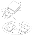
図1は、カバー付きディスクトレイ1と薄型光ディスク用カートリッジ16を示している。薄型光ディスク用カートリッジ16には、薄型光ディスク(例えば、厚さ300μm以下で、可撓性のある光フレキシブルディスク)13がトレイ1に搭載され、媒体13をそれぞれ搭載した複数のトレイ1が収容されている。この薄型光ディスク用カートリッジ16は、後述する情報記録再生装置51に装着される。そして、一枚一枚薄型光ディスク13が取り出されて情報の記録再生動作に供される(詳細は後述する)。
<Configuration of thin information recording medium tray>
FIG. 1 shows a
また、薄型光ディスク用カートリッジ16の側面には溝17が設けられている。これは情報記録再生装置51に対して位置をあわせて装着させるために利用される。ただし、位置をあわせて固定するための機構は今この限りではなく、記載はしないが、円筒形のピンやテーパー状突起などを利用したものでもよい。
A
カバー付トレイ1は、厚みが0.5mm以下、好ましくは250μm以下の薄型のシート(例えば、PET材)で構成されている。また、カバー付トレイ1のカバー11は、より薄いシート(例えば、PET材)で構成されている。そして、そのカバー11は、トレイ1の後端部15で一定の幅を持って固定(例えば、糊付け)されている。また、カバー付トレイ1の前端部には、後述するカバー剥離トリガー部材21が貫通する2つの貫通孔12と、後述するトレイ挿抜部材22がフックするためのフック孔14が設けられている。
The
<カバー剥離動作とトレイ引き抜き動作>
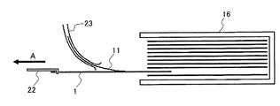
図2は、カバー11の剥離(押し上げ)動作とトレイ1のカートリッジに対する挿抜動作の原理を示している。薄型光ディスク用カートリッジ16が情報記録再生装置51(図5参照)に装着されると、水平移動機構部64(図12参照)によって駆動されるトレイ挿抜部材22が薄型光ディスク用カートリッジ16の開口部まで伸びてくる。そして、トレイ挿抜部材22の先端部が、所望の薄型光ディスク13が搭載されたトレイ1のフック孔14にフックされる。続いて、トレイ挿抜部材22がトレイ1を引き出す方向に水平移動し、所定のタイミングでカバー剥離トリガー部材21が貫通孔12に一時的に押し上げられ、それと共にカバー11の端部が持ち上がる。カバー端部が持ち上がった状態でトレイ1の水平移動が続けられると、カバー11の端部がカバー剥離ガイド23によってめくり上げられる。このように、トレイ1の引き抜き動作と連動させてカバー11を一瞬持ち上げて、持ち上げられたカバー11をカバー剥離ガイド23に引っ掛けることにより、トレイ1の水平移動(ローディング動作)と共にカバー11が完全にめくり上がるようになっている。
<Cover peeling operation and tray pulling operation>
FIG. 2 shows the principle of the
図3は、カバー付トレイ1をカートリッジ16から引き出した状態を、横から見た場合の断面図である。前述のように、トレイ1の水平移動(矢印A方向)と共にカバー11がめくり上がり、薄型光ディスク13を収納したトレイ1がトレイ載置台24に置かれ、ローディングの準備が整えられる。図4は、薄型光ディスク13を収納したトレイ1が載置台24に置かれた状態を示している。そして、トレイ1から薄型光ディスク13が上述のようにクランプ部59に固定され、記録或いは再生動作が実行される(図12参照)。
FIG. 3 is a cross-sectional view of the state in which the
記録再生動作が終了し、薄型光ディスク13をアンローディングする場合には、薄型光ディスク13がトレイ1に戻される。そして、トレイ挿抜部材22が薄型光ディスク13を収納したトレイ1をカートリッジ16内に押し戻す。
When the recording / reproducing operation is completed and the thin
しかしながら、カートリッジ16には多数のトレイ1が収納されているため、戻そうとするトレイ1の端部(図5中のX部分)に相当程度の抵抗力(摩擦や湿気に起因する抵抗力)が生じる。特に、夏場等高温多湿の環境に情報記録再生装置51が置かれている場合にはより強い抵抗力が生じる。この場合、トレイ1は、その抵抗力及びトレイ挿抜部材22により、両側から押されたような状態に置かれ、力がトレイ1中央部分に矢印C方向に掛かり、薄型の(厚さ250μm以下)トレイ1は浮き上がる方向に屈曲してしまう。そして、トレイ1の屈曲と共に、そこに収納されている薄型光ディスク13も屈曲したり、トレイ1から脱落したりするという問題が生じてしまう。
However, since a large number of
<ローラー付トレイ載置台>
そこで、本発明の実施形態では、トレイ載置台24にトレイ屈曲防止用のローラー25を設けている。
<Tray mounting table with roller>
Therefore, in the embodiment of the present invention, the tray mounting table 24 is provided with a
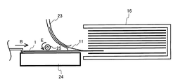
図6は、トレイ1を引き出している状態を示す図である。トレイ1を引き出すときには、トレイ1の屈曲を生じることはまずない。ただし、ローラー25によって、トレイ載置台24においてトレイ1を安定して移動させることができるという作用がある。図7に示されるように、トレイ屈曲防止用ローラー25は、トレイ載置台24に取り付け軸26によって回転自在に取り付けられている。従って、トレイ1が矢印A方向に移動すれば、ローラー25は矢印D方向に回転する。なお、トレイの屈曲防止という点のみを考えれば、必ずしもローラーを回転自在にする必要はないが、ローラー25を回転自在にすることにより、トレイ1が移動に伴って傷つくことを防止することができるようになる。トレイ1の傷つき防止と言う観点からは、ローラー25は樹脂等、トレイ1の材質(例えばPET材)以下の硬度の材料で構成されるか、そのような材料で接触面が覆われていることが好ましい。
FIG. 6 is a diagram illustrating a state in which the
図8は、ローディング位置にあるトレイ1を示している。図8で示されるように、ローディング位置にトレイ1にあるとき、何等かの力が上方向に生じた場合でも、トレイ端部押さえ部材27に加えてローラー25の作用によって、トレイ1を安定的にトレイ載置台24に載置しておくことができる。
FIG. 8 shows the
図9は、記録再生動作が終了し、薄型光ディスク13を収納したトレイ1をカートリッジ16内に押し戻す様子を示す図である。図9に示されるように、トレイ載置台24には、湾曲しやすい中央部分にローラー25が配置されている。このようにすることで、一番湾曲しやすい状態である、トレイ1の引ききりの位置でのトレイ中央部分の浮き上がりを規制することが出来るため、湾曲して座屈に至ることを防止することが出来る。なお、トレイ載置台24(或いは、後述の引き出し固定ベース66)が情報記録再生装置51内に無い場合には、図10に示すように、情報記録再生装置51内のトレイ1の移動経路上にローラー25−1及び25−2を配置し、湾曲しやすい中央部分の変形を防ぐようにすればよい。
FIG. 9 is a diagram illustrating a state in which the recording / reproducing operation is finished and the
なお、ローラー25は、トレイ1の前端部と中央部の間に設置することができる。ただし、カートリッジ16のサイズをできる限り小さくするという目的の下、薄型光ディスク13の直径とトレイ1の幅が略同一か、トレイ1の幅がほんの少しだけ大きい(ローラー25が通過するスペースは無い)場合がある。この場合には、カートリッジ16から最大限引き出したときのトレイ1の領域S1及びS2(図11参照)内であって、なるべく中央部に近い位置に対応するところにローラー25を設置するのが良い。トレイ1の後端部はカートリッジ16内に保持されているので、厳密な意味では、トレイの真中央部が屈曲するわけではなく、多少トレイ1の前端部方向にシフト位置が屈曲する。よって、領域S1及びS2内にローラー25を設置するには理にかなっていると言える。
The
<情報記録再生装置の構成及び記録媒体のローディング動作>
図12は、情報記録再生装置51の概略構成例を示している。情報記録再生装置51は、筐体52と、筐体52に設けられたカートリッジ挿入口53と、薄型光ディスク13を収納したトレイ1と、トレイ1を多数枚積層収納したカートリッジ16と、カートリッジ16を固定し上下方向に移動させるカートリッジ移動台54と、カートリッジ16からトレイ1を水平方向に引き出し又は収納するための水平移動機構64と、水平移動機構64に設けたトレイ1を引掛けるためのトレイ挿抜部材22と、水平移動機構64を水平方向に移動するための駆動部65と、トレイ1のカバー11を引き剥がすためのカバー剥離ガイド23と、トレイ1をトレイ挿抜部材22に位置決めするためのトレイ検出センサ56と、水平移動機構64と駆動部65とトレイ検出センサ56を設け、引き出したトレイ1を載せて置くための固定ベース66と、薄型光ディスク13とターンテーブル(ガラス円板)60をクランプ部59に固定し回転させるためのスピンドルモータ58と、薄型光ディスク13のデータの記録再生を行う記録再生部61と、記録再生部61を水平方向に移動するための駆動部62と、薄型光ディスク13をターンテーブル60から剥離させるための振動機構70と、スピンドルモータ58と記録再生部61と駆動部62および振動機構70を搭載し上下方向に移動する記録再生部移動台63と、薄型光ディスク13をクランプ部59に固定するキャップ67と、キャップ67を上下左右に移動できるようにガイドするキャップホルダ69と、キャップホルダ69を搭載し上下方向に移動するクランプ部移動台68と、筐体52に固定されカートリッジ移動台54の上下方向の移動を支持する支持部材25と、筐体52に固定され記録再生部移動台63とクランプ部移動台68の上下方向の移動を支持する支持部材57と、を備えている。なお、カートリッジ移動台54と記録再生部移動台63およびクランプ部移動台68は、図示しない移動機構によって駆動力が与えられ移動する。また、薄型光ディスク13と記録再生部61との間隔は、おおよそ0.65mm〜3.5mmが好適である。また、ターンテーブル(ガラス円板)の厚さは、おおよそ0.5mm〜0.6mmが好適である。
<Configuration of information recording / reproducing apparatus and loading operation of recording medium>
FIG. 12 shows a schematic configuration example of the information recording / reproducing
次に、トレイ1をカートリッジ16から引き出し薄型光ディスク13をクランプ部59にセットするロード動作を説明する。まず、カートリッジ移動台54を移動しながらトレイ検出センサ56でトレイ1の位置を検出して目標のトレイ1をトレイ挿抜部材22の水平レベルに位置決めする。次に、水平移動機構64を移動してトレイ挿抜部材22をカートリッジ16の積層されたトレイ1の隙間に挿入しトレイ1のフック孔14に引掛ける。次に、水平移動機構64を移動しカートリッジ16からトレイ1を引き出し固定ベース66(上述のトレイ載置台24に相当する)の所定の位置に位置決めする。この引き出し動作時、トレイ1のカバー11はカバー剥離ガイド23に接触し上方に引き剥がされる。また、図12のように薄型光ディスク13は、カートリッジ16から全て引き出されているがトレイ1の一部はカートリッジ16に残る構成とする。次に、記録再生部移動台63を下方に移動させ薄型光ディスク13のクランプ穴11にクランプ部59を挿入する。次に、クランプ部移動台68を上方に移動させクランプ部59の磁力によりキャップ67をクランプ部59に吸着して薄型光ディスク13を固定する。この状態でキャップ67は、キャップホルダ69と接触しない状態となる。次に、記録再生部移動台63とクランプ部移動台68を上方に移動させ薄型光ディスク13がトレイ1に接触しない所定の位置に移動する。これは、自重で垂れ下がった薄型光ディスク13をトレイ1に接触しない位置に移動してから回転させるためである。次に、スピンドルモータ58を起動し薄型光ディスク13を回転する。薄型光ディスク13は、空気流によりターンテーブル60に押付けられ面ぶれのない状態で回転する。次に、記録再生部61により薄型光ディスク13の記録再生を実行する。なお、薄型光ディスク13の面ぶれ低減に関しては、ターンテーブル60の内周側に穴を設け、空気流をターンテーブル60と薄型光ディスク13の間に流入させることでさらに効果がある。また、ターンテーブル60の下側に薄型光ディスク13を固定する構成は、記録再生部の光ビームは薄型光ディスク13に焦点を結ぶように構成されているので、ターンテーブル60の上側に塵が付着し場合でもターンテーブル60の上側の位置では、光スポットの面積が大きいため光量の低下が少なく記録再生のエラーを低減できる。
Next, a loading operation in which the
<記録媒体のアンローディング動作(トレイ収納動作を含む)>
薄型光ディスク13を記録再生状態からカートリッジ16に収納するアンローディング動作を説明する。まず、記録再生状態からスピンドルモータ58を停止したのち、振動機構70でターンテーブル60を叩く又は振動させ薄型光ディスク13をターンテーブル60から剥離させる。次に、記録再生部移動台63とクランプ部移動台68を下方に移動させ薄型光ディスク13をトレイ1に接触させる。次に、クランプ部移動台68を下方に移動させクランプ部59からキャップ67を切り離し待機状態に移動する。これにより、薄型光ディスク13はトレイ1に受け渡される。次に、記録再生部移動台63を上方に移動させ待機状態に移動する。次に、水平移動機構64を移動させトレイ挿抜部材22でトレイ1を押すようにして移動させカートリッジ16に収納する。このトレイ1がカートリッジ16の中に挿入されるに連れてカバー11は、トレイ1に戻されて薄型光ディスク13を被うようになる。次に、水平移動機構64を待機状態に戻す。
<Recording medium unloading operation (including tray storage operation)>
An unloading operation for storing the thin
このように、カートリッジ16にトレイ1に収められ積層された薄型光ディスク13を損傷することなくランダムに取り出し、薄型光ディスク13の面ぶれのない状態でデータを高精度で記録再生したのち、カートリッジ16の元の場所に、高速に、正確に薄型光ディスク13を損傷することなく戻すことができる。また、トレイ1を屈曲させることなくスムーズにカートリッジ16に戻すことができる。
As described above, the thin
<まとめ>
本実施形態では、情報記録再生装置の内部において、薄型光ディスク13を取り出すためにトレイ1を引き出して、それを引ききりの位置(最大限引き出してディスクローディングが可能な位置)まで引き出し、情報記録媒体への記録や再生を終えたのち、再びトレイ1をカートリッジ16に収納させる。そして、トレイ1をカートリッジ16に収納するときには、トレイ1を挟み、あるいは押し付ける作用をする回転自在なローラー25を設けている。これによって、収納時の座屈の原因となる中央部分の湾曲作用(図5の現象)を完全に押さえ、トレイ1が座屈を回避するようにしている。トレイ1が座屈しなければ、薄型光ディスクも安定的にローディング及びアンローディングすることができるようになる。
<Summary>
In this embodiment, inside the information recording / reproducing apparatus, the
なお、トレイ1を押し付けて位置決めする手段としては、回転自在のローラーが好ましいが、ローラーに限られるものではなく、板バネ等であっても良い。ただし、板バネの場合、バネの強度は適切に選択する必要がある。強すぎるとトレイ1を傷つけてしまし、弱すぎれば押さえる作用が充分に働かない場合もあるからである。
The means for pressing and positioning the
また、トレイ1の厚さは上述のように250μm以下が好ましい。250μmの厚さがあれば、通常の環境下でのトレイの屈曲は回避できるが、カートリッジのより高容量化のためにトレイをもっと薄くすることも考えられる。この場合には、通常の環境下でもトレイが座屈してしまう可能性もある。よって、ローラー等のトレイ座屈を防止する手段を設けることは有効である。なお、0.5mm厚のトレイを用い、気温40℃、湿度80%でカートリッジからのトレイ挿抜テストを行ったところ、トレイ後端部(カートリッジ内に保持されている部分)の最大摩擦は、0.017g/mm2であった。この場合にはローラーが無くてもトレイは屈曲しなかった。言い換えれば、これ以上の摩擦抵抗がある場合には0.5mm厚のトレイを用いてもローラーは必須となる。よって、250μm厚のトレイの場合には、0.017g/mm2以下の摩擦力であってもトレイ1が屈曲してしまう可能性が高いと言える。
Further, the thickness of the
このように、本実施形態によれば、シンプルな構成で、安定的に薄型光ディスクのローディング・アンローディングを実現することができる。そして、トレイ1の出し入れの信頼性を高めることができる。また、部品点数が少ないため安価な機構にすることができ、量産にも向く機構を実現できる。
As described above, according to the present embodiment, it is possible to stably implement loading / unloading of a thin optical disk with a simple configuration. And the reliability of taking in and out of the
Claims (7)
前記カートリッジから前記カバー付トレイを引き出すことにより取り出し、かつ、前記カバー付トレイを押し入れることにより前記カートリッジに収納する、トレイローディング手段と、
前記カバー付トレイに載置された前記情報記録媒体に対して、情報の記録及び/又は再生を行う記録再生部と、を備え、
前記トレイローディング手段は、
前記カートリッジと前記記録再生部における記録再生動作位置との間を、前記カバー付トレイを移動させるトレイ移動手段と、
前記カバー付トレイの上下方向の位置決めを行い、前記トレイ移動手段により前記カバー付トレイを前記カートリッジに収納する際に前記カバー付トレイからの前記情報記録媒体の脱落を防止するトレイ位置決め手段と、
前記トレイ移動手段によるカバー付トレイの移動に対応して、前記カバー付トレイのカバーの端部を押し上げて前記カバーをカバーガイド部にガイドし、前記情報記録媒体を露出させる媒体露出手段と、
を備えることを特徴とする情報記録再生装置。 An information recording / reproducing apparatus for recording and / or reproducing information on an information recording medium placed on a tray with a cover housed in a cartridge,
A tray loading means for taking out the tray with cover from the cartridge by taking it out, and storing it in the cartridge by pushing in the tray with cover;
A recording / reproducing unit that records and / or reproduces information with respect to the information recording medium placed on the tray with cover,
The tray loading means includes
Tray moving means for moving the tray with cover between the cartridge and a recording / reproducing operation position in the recording / reproducing unit;
Tray positioning means for performing vertical positioning of the tray with cover and preventing the information recording medium from dropping from the tray with cover when the tray with cover is stored in the cartridge by the tray moving means ;
Corresponding to the movement of the tray with cover by the tray moving means, medium exposure means for pushing up the end of the cover of the tray with cover to guide the cover to the cover guide portion and exposing the information recording medium;
An information recording / reproducing apparatus comprising:
前記トレイ位置決め手段は、前記トレイ載置台に取り付けられていることを特徴とする請求項1又は2に記載の情報記録再生装置。 In addition, when loading the information recording medium, comprising a tray mounting table for mounting the tray with cover,
The information recording / reproducing apparatus according to claim 1, wherein the tray positioning unit is attached to the tray mounting table.
。 It said tray positioning means, the information recording and reproducing apparatus according to any one of claims 1 to 4, characterized in that it is constituted by a rotatable roller in accordance with the movement of the tray with cover.
前記ローラーは、前記載置台における前記カバー付トレイの移動経路上であって、当該移動経路に平行な端部の中央付近に設けられていることを特徴とする請求項5又は6に記載の情報記録再生装置。7. The information according to claim 5, wherein the roller is provided on a movement path of the tray with cover in the mounting table and near a center of an end parallel to the movement path. Recording / playback device.
Priority Applications (1)
| Application Number | Priority Date | Filing Date | Title |
|---|---|---|---|
| JP2007152759A JP5153213B2 (en) | 2007-06-08 | 2007-06-08 | Information recording / reproducing device |
Applications Claiming Priority (1)
| Application Number | Priority Date | Filing Date | Title |
|---|---|---|---|
| JP2007152759A JP5153213B2 (en) | 2007-06-08 | 2007-06-08 | Information recording / reproducing device |
Publications (3)
| Publication Number | Publication Date |
|---|---|
| JP2008305506A JP2008305506A (en) | 2008-12-18 |
| JP2008305506A5 JP2008305506A5 (en) | 2010-07-08 |
| JP5153213B2 true JP5153213B2 (en) | 2013-02-27 |
Family
ID=40234086
Family Applications (1)
| Application Number | Title | Priority Date | Filing Date |
|---|---|---|---|
| JP2007152759A Expired - Fee Related JP5153213B2 (en) | 2007-06-08 | 2007-06-08 | Information recording / reproducing device |
Country Status (1)
| Country | Link |
|---|---|
| JP (1) | JP5153213B2 (en) |
Families Citing this family (1)
| Publication number | Priority date | Publication date | Assignee | Title |
|---|---|---|---|---|
| JP4702649B2 (en) * | 2009-01-07 | 2011-06-15 | ソニー株式会社 | Disc changer |
Family Cites Families (7)
| Publication number | Priority date | Publication date | Assignee | Title |
|---|---|---|---|---|
| JPS5339703A (en) * | 1976-09-24 | 1978-04-11 | Matsushita Electric Ind Co Ltd | Case for disc-shaped recording medium |
| JPH0197448U (en) * | 1987-12-21 | 1989-06-28 | ||
| JPH0713844B2 (en) * | 1990-07-20 | 1995-02-15 | ナカミチ株式会社 | Tray swing prevention device for disc playback device |
| JP3227915B2 (en) * | 1993-07-14 | 2001-11-12 | 松下電器産業株式会社 | Disk cartridge, disk drive device and disk changer device |
| JPH11110880A (en) * | 1997-09-30 | 1999-04-23 | Sony Corp | Recording and/or reproducing device |
| JP3801039B2 (en) * | 2001-12-10 | 2006-07-26 | ヤマハ株式会社 | Disc changer device |
| JP2004139659A (en) * | 2002-10-17 | 2004-05-13 | Ricoh Co Ltd | Disk cartridge and disk changer device |
-
2007
- 2007-06-08 JP JP2007152759A patent/JP5153213B2/en not_active Expired - Fee Related
Also Published As
| Publication number | Publication date |
|---|---|
| JP2008305506A (en) | 2008-12-18 |
Similar Documents
| Publication | Publication Date | Title |
|---|---|---|
| JP4927397B2 (en) | Optical disc cartridge and recording / reproducing apparatus | |
| US7805737B2 (en) | Disk drive device and electronic apparatus | |
| US6714507B2 (en) | Disc device | |
| JP5153213B2 (en) | Information recording / reproducing device | |
| JP4732944B2 (en) | Disk unit | |
| JP2008186539A (en) | Optical disk recording/reproducing device and disk changer | |
| JP2007115328A (en) | Recording/reproducing device and its optical cartridge | |
| US6215753B1 (en) | Recording-medium loading apparatus having a recording medium holder movable relative to a tray | |
| TWI316697B (en) | Disk drive device | |
| JP2007172728A (en) | Optical disc cartridge and recording/reproducing apparatus | |
| JP5201877B2 (en) | Information recording / reproducing device | |
| JP2006309906A (en) | Optical disk apparatus | |
| JP3437383B2 (en) | Disc changer | |
| KR100585134B1 (en) | Apparatus for holding disk and disk tray provided with the same | |
| US8087040B2 (en) | Slot-in type disk drive | |
| JP2008176873A (en) | Information recording/reproducing device | |
| JP4184285B2 (en) | Disk unit | |
| JP2001357595A (en) | Disk changer | |
| JP5127611B2 (en) | Optical disc recording / reproducing apparatus and optical disc tray used therein | |
| JP4884293B2 (en) | Disk unit | |
| JP5136092B2 (en) | Disc player | |
| JP4166214B2 (en) | Disc tray device and recording / reproducing device including the disc tray device | |
| JP2006012340A (en) | Optical disk reproducing device | |
| JP2009158021A (en) | Flexible optical disk recording and reproducing device | |
| JP2007207399A (en) | Recording medium driving device and electronic equipment |
Legal Events
| Date | Code | Title | Description |
|---|---|---|---|
| A711 | Notification of change in applicant |
Free format text: JAPANESE INTERMEDIATE CODE: A711 Effective date: 20100415 |
|
| A521 | Written amendment |
Free format text: JAPANESE INTERMEDIATE CODE: A523 Effective date: 20100520 |
|
| A621 | Written request for application examination |
Free format text: JAPANESE INTERMEDIATE CODE: A621 Effective date: 20100520 |
|
| A977 | Report on retrieval |
Free format text: JAPANESE INTERMEDIATE CODE: A971007 Effective date: 20120202 |
|
| A131 | Notification of reasons for refusal |
Free format text: JAPANESE INTERMEDIATE CODE: A131 Effective date: 20120214 |
|
| A521 | Written amendment |
Free format text: JAPANESE INTERMEDIATE CODE: A523 Effective date: 20120416 |
|
| TRDD | Decision of grant or rejection written | ||
| A01 | Written decision to grant a patent or to grant a registration (utility model) |
Free format text: JAPANESE INTERMEDIATE CODE: A01 Effective date: 20121113 |
|
| A61 | First payment of annual fees (during grant procedure) |
Free format text: JAPANESE INTERMEDIATE CODE: A61 Effective date: 20121204 |
|
| FPAY | Renewal fee payment (event date is renewal date of database) |
Free format text: PAYMENT UNTIL: 20151214 Year of fee payment: 3 |
|
| R150 | Certificate of patent or registration of utility model |
Free format text: JAPANESE INTERMEDIATE CODE: R150 |
|
| R250 | Receipt of annual fees |
Free format text: JAPANESE INTERMEDIATE CODE: R250 |
|
| LAPS | Cancellation because of no payment of annual fees |