JP5152987B2 - Cover for underground structure - Google Patents
Cover for underground structure Download PDFInfo
- Publication number
- JP5152987B2 JP5152987B2 JP2008253983A JP2008253983A JP5152987B2 JP 5152987 B2 JP5152987 B2 JP 5152987B2 JP 2008253983 A JP2008253983 A JP 2008253983A JP 2008253983 A JP2008253983 A JP 2008253983A JP 5152987 B2 JP5152987 B2 JP 5152987B2
- Authority
- JP
- Japan
- Prior art keywords
- base plate
- lid
- frame
- recess
- edge
- Prior art date
- Legal status (The legal status is an assumption and is not a legal conclusion. Google has not performed a legal analysis and makes no representation as to the accuracy of the status listed.)
- Active
Links
- 229920005989 resin Polymers 0.000 claims description 17
- 239000011347 resin Substances 0.000 claims description 17
- 229910001018 Cast iron Inorganic materials 0.000 claims description 9
- 230000005540 biological transmission Effects 0.000 claims description 6
- 239000000463 material Substances 0.000 claims description 4
- 239000012530 fluid Substances 0.000 claims description 3
- XEEYBQQBJWHFJM-UHFFFAOYSA-N Iron Chemical compound [Fe] XEEYBQQBJWHFJM-UHFFFAOYSA-N 0.000 description 10
- 229910052742 iron Inorganic materials 0.000 description 5
- 238000012423 maintenance Methods 0.000 description 5
- 230000002093 peripheral effect Effects 0.000 description 5
- 238000010079 rubber tapping Methods 0.000 description 3
- 239000004576 sand Substances 0.000 description 2
- XLYOFNOQVPJJNP-UHFFFAOYSA-N water Substances O XLYOFNOQVPJJNP-UHFFFAOYSA-N 0.000 description 2
- 101100206395 Caenorhabditis elegans tag-250 gene Proteins 0.000 description 1
- 230000000994 depressogenic effect Effects 0.000 description 1
- 230000006866 deterioration Effects 0.000 description 1
- 230000005674 electromagnetic induction Effects 0.000 description 1
- 239000003822 epoxy resin Substances 0.000 description 1
- 239000006260 foam Substances 0.000 description 1
- 238000001746 injection moulding Methods 0.000 description 1
- 230000007774 longterm Effects 0.000 description 1
- 229920000515 polycarbonate Polymers 0.000 description 1
- 239000004417 polycarbonate Substances 0.000 description 1
- 229920000647 polyepoxide Polymers 0.000 description 1
- 230000002265 prevention Effects 0.000 description 1
- 239000010865 sewage Substances 0.000 description 1
- 229920005992 thermoplastic resin Polymers 0.000 description 1
Images


Description
本発明は、蓋本体とこの蓋本体を開閉可能に支持する受枠とを備えた地下構造物用蓋に関する。 The present invention relates to a lid for an underground structure including a lid body and a receiving frame that supports the lid body so as to be opened and closed.
なお、本願明細書でいう「地下構造物用蓋」とは、下水道における地下埋設物,地下構造施設等と地上とを通じる開口部を閉塞するマンホール蓋,大型鉄蓋,汚水桝蓋、電力・通信における地下施設機器や地下ケーブル等を保護する開閉可能な共同溝用鉄蓋,送電用鉄蓋,配電用鉄蓋、上水道やガス配管における路面下の埋設導管およびその付属機器と地上とを結ぶ開閉扉としての機能を有する消火栓蓋,制水弁蓋,仕切弁蓋,空気弁蓋,ガス配管用蓋,量水器蓋等を総称する。 In addition, the term “underground structure lid” as used in the present specification means a manhole cover, a large iron cover, a sewage culm lid, an electric power / Openable and closable joint gutter lids, power transmission iron lids, power distribution iron lids, buried underground pipes in waterworks and gas pipes, and their associated equipment to protect underground facilities equipment and underground cables in communications A fire hydrant lid, a water control valve lid, a gate valve lid, an air valve lid, a gas pipe lid, a water meter lid, etc., that function as an open / close door.
従来より、地下構造物用蓋においては、鋳鉄製の蓋本体の凹部に、エポキシ樹脂等からなる着色樹脂を充填することにより、色彩豊かなデザインとして路上の景観性を向上させたり、地下に埋設された施設や装置の表示をして維持管理の利便性や視認性を向上させることが行われている。 Conventionally, lids for underground structures have been filled with colored resin, such as epoxy resin, in the recesses of the lid body made of cast iron, improving the landscape on the road as a colorful design, or being buried underground The convenience and visibility of maintenance are improved by displaying the facilities and devices that have been used.
このような地下構造物用蓋としては、特許文献1に記載の地下構造物用カラー鉄蓋がある。これは、鉄蓋本体の表面に凸部と凹部とで模様を形成し、凹部に着色樹脂を充填したものである。
しかしながら、このように鋳鉄製の蓋本体の凹部に着色樹脂を充填すると、着色樹脂が凝固する際の収縮によって、当初から蓋本体と着色樹脂との間に隙間を生じることがあり、隙間がない場合であっても内部応力が残存しているところに、車両の通過等による繰り返し荷重が加わることによって剥離が生じてしまい、景観性や視認性が悪化するという問題があった。 However, when the colored resin is filled in the concave portion of the lid body made of cast iron in this way, a gap may be generated between the lid body and the colored resin from the beginning due to shrinkage when the colored resin is solidified, and there is no gap. Even in such a case, there is a problem that, when the internal stress remains, peeling occurs due to repeated load due to passing of the vehicle or the like, and the scenery and visibility are deteriorated.
また、景観性や視認性を再度向上させるためには、蓋本体自体を交換する必要があるため、維持管理者のコスト負担も大きくなるという問題があった。 Moreover, since it is necessary to replace the lid body itself in order to improve the landscape and visibility again, there is a problem that the cost burden on the maintenance manager also increases.
本発明は、上記の問題点に鑑みてなされたもので、その課題は、景観性や視認性を向上させることができるとともに、その景観性や視認性を長期に亘り維持することができる地下構造物用蓋を提供することにある。 The present invention has been made in view of the above-mentioned problems, and the problem is that the landscape structure and visibility can be improved and the landscape structure and visibility can be maintained over a long period of time. The object is to provide an object lid.
本発明は、丸型の蓋本体とこの蓋本体を開閉可能に支持する受枠とを備えた地下構造物用蓋において、前記蓋本体は、周囲に縁部を有し、この縁部に囲まれた部分を窪部とした鋳鉄製のフレームと、前記フレームの窪部に装着可能な樹脂製のベースプレートとを備え、前記ベースプレートは、前記フレームの窪部に嵌め込まれて着脱可能に固定され、前記ベースプレートの外周の上部側に、前記フレームの縁部内径よりわずかに径大となる曲面状の突起部が全周にわたり形成されたことを特徴とするものである。 The present invention provides a lid for an underground structure including a round lid body and a receiving frame that supports the lid body so that the lid body can be opened and closed. The lid body has an edge around the periphery, and is surrounded by the edge. A cast iron frame having a recessed portion as a recessed portion, and a resin base plate that can be attached to the recessed portion of the frame, and the base plate is detachably fixed by being fitted into the recessed portion of the frame , A curved protrusion having a diameter slightly larger than the inner diameter of the edge of the frame is formed on the entire outer periphery of the base plate .
本発明においては、樹脂製のベースプレートにデザインや表示を入れることにより、景観性や視認性を向上させることができる。そして、この樹脂製のベースプレートを鋳鉄製のフレームの窪部に嵌め込んで一体化することによって、フレームとベースプレートを隙間なく一体化でき、しかも過剰な内部応力が残存することもないので、車両の通過等による繰り返し荷重が加わってもベースプレートが容易に外れることはない。したがって、ベースプレートによる景観性や視認性を長期に亘り維持することができる。さらに、デザインや表示の変更時には、ベースプレートのみを取り外して交換することができるため経済的である。加えて、蓋本体の大部分を占めるベースプレートが樹脂製であるため、軽量化を図ることができる。さらに、ベースプレートの外周の上部側に、前記フレームの縁部内径よりわずかに径大となる曲面状の突起部を全周にわたり形成している。このような構成とすることで、ベースプレートの外周の突起部がフレームの縁部の内周面に確実に当接するので、フレームとベースプレートとの間から雨水や土砂が浸入することをより確実に防止することができる。したがって、ベースプレートにICタグ等の電子部品を取り付けた場合でも性能を維持することができる。また、鋳鉄製のフレーム自体の劣化も防止することができる。さらに、樹脂製のベースプレートと鋳鉄製のフレームの間に寸法誤差がある場合でも、ベースプレートの突起部がフレームの縁部の内周面に当接することにより、両者を確実に嵌め合わせて一体化させることができる。 In the present invention, scenery and visibility can be improved by putting a design and display on a resin base plate. And by fitting this resin base plate into the recess of the cast iron frame and integrating it, the frame and the base plate can be integrated without gaps, and there is no excessive internal stress remaining. The base plate does not easily come off even when a repeated load is applied due to passage or the like. Therefore, the landscape and visibility of the base plate can be maintained for a long time. Furthermore, when changing the design or display, it is economical because only the base plate can be removed and replaced. In addition, since the base plate that occupies most of the lid body is made of resin, the weight can be reduced. Further, a curved projection having a diameter slightly larger than the inner diameter of the edge of the frame is formed on the entire upper side of the outer periphery of the base plate. With this configuration, the protrusions on the outer periphery of the base plate reliably come into contact with the inner peripheral surface of the edge of the frame, so rainwater and earth and sand can be more reliably prevented from entering between the frame and the base plate. can do. Therefore, the performance can be maintained even when an electronic component such as an IC tag is attached to the base plate. Further, deterioration of the cast iron frame itself can be prevented. Furthermore, even if there is a dimensional error between the resin base plate and the cast iron frame, the protrusions of the base plate abut against the inner peripheral surface of the edge of the frame, so that they can be securely fitted and integrated. be able to.
また、本発明においては、ベースプレートに、ICタグ等の情報伝達媒体を取り付けることができる。これによって、景観性や視認性の向上に加えて、維持管理作業の利便性を向上させることができ、ベースプレートを多機能に活用することができる。さらに、ベースプレートの裏面に形成された凹部内に、ICタグが前記凹部の底面側に嵌め込まれる樹脂等の非磁性材料の固定部材の上面に載置された状態で配置されており、これによって、電磁波の乱れを防止することができる。 In the present invention, an information transmission medium such as an IC tag can be attached to the base plate. Thereby, in addition to the improvement in landscape and visibility, the convenience of maintenance work can be improved, and the base plate can be utilized for multiple functions. Further, in the recess formed on the back surface of the base plate, the IC tag is disposed in a state of being placed on the upper surface of a fixing member made of a nonmagnetic material such as a resin fitted on the bottom surface side of the recess, Disturbance of electromagnetic waves can be prevented.
さらに、本発明においては、ベースプレートの表面には、弁栓類の種類、口径、流体の種類、流れ方向、管理番号等の情報を表示する各種の情報表示プレートを情報伝達媒体として取り付けることができる。これによって、景観性や視認性の向上に加えて、維持管理作業の利便性を向上させることができ、ベースプレートを多機能に活用することができる。Furthermore, in the present invention, various information display plates for displaying information such as the types of valve plugs, the diameter, the type of fluid, the flow direction, and the management number can be attached to the surface of the base plate as an information transmission medium. . Thereby, in addition to the improvement in landscape and visibility, the convenience of maintenance work can be improved, and the base plate can be utilized for multiple functions.
本発明によれば、地下構造物用蓋の景観性や視認性を向上させることができるとともに、その景観性や視認性を長期に亘り維持することができる。 ADVANTAGE OF THE INVENTION According to this invention, while being able to improve the landscape property and visibility of the lid | cover for underground structures, the landscape property and visibility can be maintained over a long term.
以下、図面に示す実施例に基づき本発明の実施の形態を説明する。 Embodiments of the present invention will be described below based on examples shown in the drawings.
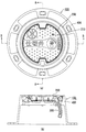
図1は、本発明の地下構造物用蓋の一実施例を示し、(a)は平面図、(b)は(a)のA−A断面図である。 1A and 1B show an embodiment of a lid for an underground structure according to the present invention, in which FIG. 1A is a plan view and FIG. 1B is a cross-sectional view taken along line AA in FIG.
図1に示す地下構造物用蓋100は仕切弁蓋であり、蓋本体200と、この蓋本体200を蝶番機構300を介して開閉可能に支持する受枠400とを備えて構成されている。
The
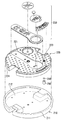
図2は、蓋本体200の構成を示す分解斜視図である。蓋本体200は、周囲に縁部211を有し、この縁部211に囲まれた部分を窪部212として略盆形状に形成した鋳鉄製のフレーム210と、このフレーム210の窪部212に装着可能な樹脂製のベースプレート220とを備え、ベースプレート220はフレーム210の窪部212に嵌め込まれて着脱可能に固定される。
FIG. 2 is an exploded perspective view showing the configuration of the
ベースプレート220は、耐摩耗性、耐衝撃性および耐圧縮強度を有するポリカーボネート等の熱可塑性樹脂製で、射出成形等によって成形され、その表面には、スリップ防止およびデザインとして複数の凸部221が設けられている。また、ベースプレート220の表面には、弁栓類の種類、口径、流体の種類、流れ方向、管理番号等の情報を表示する各種の情報表示プレート230が情報伝達媒体として取り付けられる。さらに、ベースプレート220の裏面には、無線で位置情報やメンテナンス情報等の読み取りおよび書き込みが可能なICタグ240が情報伝達媒体として取り付けられる。
The
ICタグ240は、具体的には、図3に示すベースプレート220の裏面に円形リブによって形成した凹部222に挿入され、その下側から図2に示す弾性を有する樹脂発泡体からなる固定部材250を嵌め込むことで、図4に示すように、固定部材250の上面に載置された状態で凹部222内の所定の高さ位置に配置される。そして、ICタグ240の装着位置がベースプレート220の表面側からわかるように、ベースプレート220の表面には、ICタグ240の装着位置に対応する位置に図2に示すICタグ位置表示マーク223が設けられている。
Specifically, the
実施例ではICタグ240として、通信距離が数10cm、通信周波数が13.56MHzの電磁誘導方式のパッシブタグを使用した。この場合、固定部材250の材質は、電磁波の乱れを防止する点からは、樹脂等の非磁性材料とすることが好ましい。
In the embodiment, an electromagnetic induction passive tag having a communication distance of several tens of cm and a communication frequency of 13.56 MHz was used as the
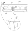
図5は、図1(a)のB−B断面による蓋本体200の要部の拡大断面図である。同図に示すように、ベースプレート220の外周には、フレーム210の縁部211内径よりわずかに径大となる四分割円状の突起部224が全周にわたり形成されており、この突起部224がフレーム210の縁部211内周面に確実に当接することで、ベースプレート220がフレーム210に確実に嵌め合わされて一体化される。また、ベースプレート220とフレーム210との一体化をより確実にするため、フレーム210の裏面側からタッピングねじ260を装着し、ベースプレート220とフレーム210とを締結するようにしている。なお、タッピングねじ260を取り外せば、ベースプレート220をフレーム210から取り外せるようになり、ベースプレート220のみの交換が可能となる。
FIG. 5 is an enlarged cross-sectional view of the main part of the lid
ここで、突起部224の縦断面形状は、ベースプレート220を押し込んだときにフレーム210の縁部211内周面に当接しながらスムーズに嵌り込むように、四分割円状や半円状等の曲面状とすることが好ましい。また、突起部224を設ける位置は、雨水や土砂の流入を防止するため、ベースプレート220外周面の上部側が好ましい。
Here, the vertical cross-sectional shape of the
以上のとおり、本発明においては、樹脂製のベースプレート220を鋳鉄製のフレーム210の窪部212に嵌め込んで一体化することによって、フレーム210とベースプレート220を隙間なく一体化できる。したがって、ベースプレート220による景観性や視認性を長期に亘り維持することができる。
As described above, in the present invention, the
なお、実施例では、本発明を仕切弁蓋に適用したが、マンホール蓋や消火栓蓋などのその他の地下構造物用蓋にも適用可能である。 In the embodiment, the present invention is applied to the gate valve cover, but it can also be applied to other underground structure covers such as a manhole cover and a fire hydrant cover.
100 地下構造物用蓋
200 蓋本体
210 フレーム
211 縁部
212 窪部
220 ベースプレート
221 凸部
222 凹部
223 ICタグ位置表示マーク
224 突起部
230 情報表示プレート
240 ICタグ
250 固定部材
260 タッピングねじ
300 蝶番機構
400 受枠
DESCRIPTION OF
Claims (3)
前記蓋本体は、周囲に縁部を有し、この縁部に囲まれた部分を窪部とした鋳鉄製のフレームと、前記フレームの窪部に装着可能な樹脂製のベースプレートとを備え、
前記ベースプレートは、前記フレームの窪部に嵌め込まれて着脱可能に固定され、
前記ベースプレートの外周の上部側に、前記フレームの縁部内径よりわずかに径大となる曲面状の突起部が全周にわたり形成されたことを特徴とする地下構造物用蓋。 In a lid for an underground structure including a round lid body and a receiving frame that supports the lid body so as to be openable and closable,
The lid body has an edge around the periphery, and includes a cast iron frame having a recess surrounded by the edge, and a resin base plate that can be attached to the recess of the frame,
The base plate is detachably fixed by being fitted into the recess of the frame ,
A lid for an underground structure , wherein a curved protrusion having a diameter slightly larger than the inner diameter of the edge of the frame is formed on the upper side of the outer periphery of the base plate over the entire circumference .
Priority Applications (1)
| Application Number | Priority Date | Filing Date | Title |
|---|---|---|---|
| JP2008253983A JP5152987B2 (en) | 2008-09-30 | 2008-09-30 | Cover for underground structure |
Applications Claiming Priority (1)
| Application Number | Priority Date | Filing Date | Title |
|---|---|---|---|
| JP2008253983A JP5152987B2 (en) | 2008-09-30 | 2008-09-30 | Cover for underground structure |
Publications (3)
| Publication Number | Publication Date |
|---|---|
| JP2010084407A JP2010084407A (en) | 2010-04-15 |
| JP2010084407A5 JP2010084407A5 (en) | 2011-10-13 |
| JP5152987B2 true JP5152987B2 (en) | 2013-02-27 |
Family
ID=42248642
Family Applications (1)
| Application Number | Title | Priority Date | Filing Date |
|---|---|---|---|
| JP2008253983A Active JP5152987B2 (en) | 2008-09-30 | 2008-09-30 | Cover for underground structure |
Country Status (1)
| Country | Link |
|---|---|
| JP (1) | JP5152987B2 (en) |
Families Citing this family (2)
| Publication number | Priority date | Publication date | Assignee | Title |
|---|---|---|---|---|
| JP5685730B2 (en) * | 2011-08-09 | 2015-03-18 | 株式会社ライセンス&プロパティコントロール | The lid body of the lid for underground structures |
| GB201406395D0 (en) * | 2014-04-09 | 2014-05-21 | Wrekin Holdings Ltd | Cast ground surface access items |
Family Cites Families (4)
| Publication number | Priority date | Publication date | Assignee | Title |
|---|---|---|---|---|
| DE3530128A1 (en) * | 1985-08-23 | 1987-02-26 | Richard Dannhaeuser | SHAFT COVER |
| JP2657273B2 (en) * | 1994-07-21 | 1997-09-24 | 福西鑄物株式会社 | Road surface installation members |
| JPH09209379A (en) * | 1996-02-01 | 1997-08-12 | Sumitomo Rubber Ind Ltd | Structure of lid for cable-laying hole |
| JP2008150903A (en) * | 2006-12-19 | 2008-07-03 | Cs Engineers:Kk | Ic tag mounting device for manhole |
-
2008
- 2008-09-30 JP JP2008253983A patent/JP5152987B2/en active Active
Also Published As
| Publication number | Publication date |
|---|---|
| JP2010084407A (en) | 2010-04-15 |
Similar Documents
| Publication | Publication Date | Title |
|---|---|---|
| US8985903B1 (en) | Bell-hole pipeline protection system | |
| US20120262037A1 (en) | Waterproof device | |
| JP5152987B2 (en) | Cover for underground structure | |
| US9322144B2 (en) | Manhole cover assembly with cams | |
| US20170023612A1 (en) | Meter Box Lid | |
| JP5685730B2 (en) | The lid body of the lid for underground structures | |
| US20190218743A1 (en) | Cover for use on public roads | |
| JP5152988B2 (en) | Cover for underground structure | |
| KR101114956B1 (en) | Cable grand and ground equipment box including that | |
| US20220299550A1 (en) | Utility cover for use with automated metering equipment | |
| KR102141042B1 (en) | Inner cover assembly for manhole | |
| US9816247B2 (en) | Lid for underground structure | |
| CN111043373B (en) | Modular valve and hydrant cover | |
| KR20090005885U (en) | A Manhole Cover | |
| KR20190082613A (en) | Manhole structure | |
| CN203960905U (en) | Double shielding well lid | |
| US20090145917A1 (en) | Tamper-Proof Irrigation Box | |
| CN103993614A (en) | Double-layer protective well lid | |
| JP3120371U (en) | Manhole cover | |
| CN201554040U (en) | Electric power cable duct cover plate | |
| GB2543338A (en) | Detector access chamber | |
| JP3238654B2 (en) | Manhole cover applicable to ledger mapping system | |
| KR100530616B1 (en) | Concrete cover mounting structure for safeguard of sea bottom cable | |
| KR200253292Y1 (en) | A manhole | |
| KR20140123346A (en) | Watertight manhole of production well for riverbed filtration and install method of the manhole |
Legal Events
| Date | Code | Title | Description |
|---|---|---|---|
| A521 | Request for written amendment filed |
Free format text: JAPANESE INTERMEDIATE CODE: A821 Effective date: 20110826 Free format text: JAPANESE INTERMEDIATE CODE: A523 Effective date: 20110826 |
|
| A621 | Written request for application examination |
Free format text: JAPANESE INTERMEDIATE CODE: A621 Effective date: 20110826 |
|
| RD02 | Notification of acceptance of power of attorney |
Free format text: JAPANESE INTERMEDIATE CODE: A7422 Effective date: 20110826 |
|
| A977 | Report on retrieval |
Free format text: JAPANESE INTERMEDIATE CODE: A971007 Effective date: 20120712 |
|
| A131 | Notification of reasons for refusal |
Free format text: JAPANESE INTERMEDIATE CODE: A131 Effective date: 20120720 |
|
| A521 | Request for written amendment filed |
Free format text: JAPANESE INTERMEDIATE CODE: A523 Effective date: 20120918 |
|
| TRDD | Decision of grant or rejection written | ||
| A01 | Written decision to grant a patent or to grant a registration (utility model) |
Free format text: JAPANESE INTERMEDIATE CODE: A01 Effective date: 20121109 |
|
| A61 | First payment of annual fees (during grant procedure) |
Free format text: JAPANESE INTERMEDIATE CODE: A61 Effective date: 20121203 |
|
| FPAY | Renewal fee payment (event date is renewal date of database) |
Free format text: PAYMENT UNTIL: 20151214 Year of fee payment: 3 |
|
| R150 | Certificate of patent or registration of utility model |
Ref document number: 5152987 Country of ref document: JP Free format text: JAPANESE INTERMEDIATE CODE: R150 Free format text: JAPANESE INTERMEDIATE CODE: R150 |
|
| R250 | Receipt of annual fees |
Free format text: JAPANESE INTERMEDIATE CODE: R250 |
|
| S111 | Request for change of ownership or part of ownership |
Free format text: JAPANESE INTERMEDIATE CODE: R313113 |
|
| R350 | Written notification of registration of transfer |
Free format text: JAPANESE INTERMEDIATE CODE: R350 |
|
| SZ03 | Written request for cancellation of trust registration |
Free format text: JAPANESE INTERMEDIATE CODE: R313Z03 |
|
| R350 | Written notification of registration of transfer |
Free format text: JAPANESE INTERMEDIATE CODE: R350 |
|
| R250 | Receipt of annual fees |
Free format text: JAPANESE INTERMEDIATE CODE: R250 |
|
| R250 | Receipt of annual fees |
Free format text: JAPANESE INTERMEDIATE CODE: R250 |
|
| R250 | Receipt of annual fees |
Free format text: JAPANESE INTERMEDIATE CODE: R250 |
|
| R250 | Receipt of annual fees |
Free format text: JAPANESE INTERMEDIATE CODE: R250 |
|
| R250 | Receipt of annual fees |
Free format text: JAPANESE INTERMEDIATE CODE: R250 |
|
| R250 | Receipt of annual fees |
Free format text: JAPANESE INTERMEDIATE CODE: R250 |
|
| R250 | Receipt of annual fees |
Free format text: JAPANESE INTERMEDIATE CODE: R250 |
|
| R250 | Receipt of annual fees |
Free format text: JAPANESE INTERMEDIATE CODE: R250 |