JP5150939B2 - Optical characteristic measuring apparatus and optical characteristic measuring method - Google Patents
Optical characteristic measuring apparatus and optical characteristic measuring method Download PDFInfo
- Publication number
- JP5150939B2 JP5150939B2 JP2009187734A JP2009187734A JP5150939B2 JP 5150939 B2 JP5150939 B2 JP 5150939B2 JP 2009187734 A JP2009187734 A JP 2009187734A JP 2009187734 A JP2009187734 A JP 2009187734A JP 5150939 B2 JP5150939 B2 JP 5150939B2
- Authority
- JP
- Japan
- Prior art keywords
- spectrum
- measurement
- correction
- dark
- photodetector
- Prior art date
- Legal status (The legal status is an assumption and is not a legal conclusion. Google has not performed a legal analysis and makes no representation as to the accuracy of the status listed.)
- Active
Links
- 230000003287 optical effect Effects 0.000 title claims description 72
- 238000000034 method Methods 0.000 title description 50
- 238000001228 spectrum Methods 0.000 claims description 228
- 238000005259 measurement Methods 0.000 claims description 218
- 238000012937 correction Methods 0.000 claims description 171
- 238000001514 detection method Methods 0.000 claims description 103
- 238000012545 processing Methods 0.000 claims description 96
- 238000000691 measurement method Methods 0.000 claims description 5
- 230000000875 corresponding effect Effects 0.000 description 40
- 238000012986 modification Methods 0.000 description 40
- 230000004048 modification Effects 0.000 description 40
- 239000000872 buffer Substances 0.000 description 26
- 230000008569 process Effects 0.000 description 24
- 238000010586 diagram Methods 0.000 description 17
- 238000000605 extraction Methods 0.000 description 9
- 238000004364 calculation method Methods 0.000 description 8
- 230000005540 biological transmission Effects 0.000 description 6
- 230000000903 blocking effect Effects 0.000 description 5
- 239000013307 optical fiber Substances 0.000 description 5
- 230000008859 change Effects 0.000 description 4
- 238000004891 communication Methods 0.000 description 4
- 230000000694 effects Effects 0.000 description 3
- 238000011156 evaluation Methods 0.000 description 3
- WFKWXMTUELFFGS-UHFFFAOYSA-N tungsten Chemical compound [W] WFKWXMTUELFFGS-UHFFFAOYSA-N 0.000 description 3
- 229910052721 tungsten Inorganic materials 0.000 description 3
- 239000010937 tungsten Substances 0.000 description 3
- 238000005516 engineering process Methods 0.000 description 2
- 239000004065 semiconductor Substances 0.000 description 2
- 230000003595 spectral effect Effects 0.000 description 2
- 230000001360 synchronised effect Effects 0.000 description 2
- 238000013459 approach Methods 0.000 description 1
- 230000002596 correlated effect Effects 0.000 description 1
- 239000006185 dispersion Substances 0.000 description 1
- 230000008030 elimination Effects 0.000 description 1
- 238000003379 elimination reaction Methods 0.000 description 1
- 230000007613 environmental effect Effects 0.000 description 1
- 230000006870 function Effects 0.000 description 1
- 238000007689 inspection Methods 0.000 description 1
- 239000004973 liquid crystal related substance Substances 0.000 description 1
- 238000004519 manufacturing process Methods 0.000 description 1
- 239000011159 matrix material Substances 0.000 description 1
- 230000007246 mechanism Effects 0.000 description 1
- 230000002093 peripheral effect Effects 0.000 description 1
- 230000009467 reduction Effects 0.000 description 1
- 230000002123 temporal effect Effects 0.000 description 1
Images


Classifications
-
- G—PHYSICS
- G01—MEASURING; TESTING
- G01J—MEASUREMENT OF INTENSITY, VELOCITY, SPECTRAL CONTENT, POLARISATION, PHASE OR PULSE CHARACTERISTICS OF INFRARED, VISIBLE OR ULTRAVIOLET LIGHT; COLORIMETRY; RADIATION PYROMETRY
- G01J3/00—Spectrometry; Spectrophotometry; Monochromators; Measuring colours
-
- G—PHYSICS
- G01—MEASURING; TESTING
- G01J—MEASUREMENT OF INTENSITY, VELOCITY, SPECTRAL CONTENT, POLARISATION, PHASE OR PULSE CHARACTERISTICS OF INFRARED, VISIBLE OR ULTRAVIOLET LIGHT; COLORIMETRY; RADIATION PYROMETRY
- G01J3/00—Spectrometry; Spectrophotometry; Monochromators; Measuring colours
- G01J3/02—Details
- G01J3/0205—Optical elements not provided otherwise, e.g. optical manifolds, diffusers, windows
- G01J3/0232—Optical elements not provided otherwise, e.g. optical manifolds, diffusers, windows using shutters
-
- G—PHYSICS
- G01—MEASURING; TESTING
- G01J—MEASUREMENT OF INTENSITY, VELOCITY, SPECTRAL CONTENT, POLARISATION, PHASE OR PULSE CHARACTERISTICS OF INFRARED, VISIBLE OR ULTRAVIOLET LIGHT; COLORIMETRY; RADIATION PYROMETRY
- G01J3/00—Spectrometry; Spectrophotometry; Monochromators; Measuring colours
- G01J3/28—Investigating the spectrum
-
- G—PHYSICS
- G01—MEASURING; TESTING
- G01J—MEASUREMENT OF INTENSITY, VELOCITY, SPECTRAL CONTENT, POLARISATION, PHASE OR PULSE CHARACTERISTICS OF INFRARED, VISIBLE OR ULTRAVIOLET LIGHT; COLORIMETRY; RADIATION PYROMETRY
- G01J1/00—Photometry, e.g. photographic exposure meter
- G01J1/02—Details
- G01J1/0219—Electrical interface; User interface
Description
この発明は、光学特性測定装置および光学特性測定方法に関し、特にスペクトルを高精度に測定するための技術に関する。 The present invention relates to an optical characteristic measuring apparatus and an optical characteristic measuring method, and more particularly to a technique for measuring a spectrum with high accuracy.
従来から、発光体などの評価を行なうための技術として、分光計測が広く用いられている。このような分光計測に用いられる光学特性測定装置では、一般的に、測定対象の発光体などからの測定光を分光器(典型的には、回折格子)を用いて成分波長に分光し、分光された各成分波長を光検出器で検出する。測定光以外の影響を極力低減するために、これらの分光器や光検出器は、筐体内に収納される。 Conventionally, spectroscopic measurement has been widely used as a technique for evaluating light emitters and the like. In such an optical characteristic measurement apparatus used for spectroscopic measurement, generally, measurement light from a light emitting body to be measured is spectrally divided into component wavelengths using a spectroscope (typically, a diffraction grating), and spectrally separated. Each detected component wavelength is detected by a photodetector. In order to reduce the influence other than the measurement light as much as possible, these spectroscopes and photodetectors are accommodated in a housing.
しかしながら、現実的には、光検出器による検出結果は、筐体内部の乱反射した光、分光器表面で拡散反射した光、および測定次数以外の次数をもつ光などの影響を受け得る。一般的に、これらの光は「迷光」と称される。このような意図しない迷光による影響を抑制するために、各種の方法が提案されている。 However, in reality, the detection result by the photodetector may be affected by light that is irregularly reflected inside the housing, light that is diffusely reflected by the spectroscope surface, light that has an order other than the measurement order, and the like. Generally, these lights are referred to as “stray light”. Various methods have been proposed to suppress the influence of such unintended stray light.
たとえば、特開平11−030552号公報(特許文献1)には、分光光度計の分散光学系から導かれた光を多数の受光素子を有する受光器によって測定する場合に生じる迷光の影響を、当該分光光度計の測定定数として正確に見積り、その影響を除去する迷光補正方法が開示されている。 For example, Japanese Patent Application Laid-Open No. 11-030552 (Patent Document 1) describes the influence of stray light generated when light guided from a dispersion optical system of a spectrophotometer is measured by a light receiver having a large number of light receiving elements. A stray light correction method that accurately estimates the measurement constant of a spectrophotometer and removes the influence thereof is disclosed.
また、特開2002−005741号公報(特許文献2)には、スペクトル測定装置内部に発生する迷光や、検出素子の表面の反射や回折により生ずる不要な光の影響を、検出信号の処理により取り除き、精度のよいスペクトル強度信号を得ることのできる、スペクトル測定装置が開示されている。 Japanese Patent Laid-Open No. 2002-005741 (Patent Document 2) removes the influence of stray light generated in the spectrum measuring apparatus and unnecessary light caused by reflection or diffraction of the surface of the detection element by processing the detection signal. A spectrum measuring apparatus capable of obtaining a spectrum intensity signal with high accuracy is disclosed.
しかしながら、特開平11−030552号公報(特許文献1)に開示された迷光補正方法では、各受光素子で測定した受光信号強度と、当該波長に対応する受光素子によって測定した受光信号強度との比を、検出器を構成する受光素子の数だけ算出する必要がある。そのため、相対的に多くの時間を要するといった課題がある。 However, in the stray light correction method disclosed in Japanese Patent Laid-Open No. 11-030552 (Patent Document 1), the ratio between the received light signal intensity measured by each light receiving element and the received light signal intensity measured by the light receiving element corresponding to the wavelength. Need to be calculated for the number of light receiving elements constituting the detector. Therefore, there is a problem that a relatively long time is required.
また、特開2002−005741号公報(特許文献2)に記載のスペクトル測定装置は、その補正処理の具体的な内容を開示するものではない。 Moreover, the spectrum measuring apparatus described in Japanese Patent Laid-Open No. 2002-005741 (Patent Document 2) does not disclose the specific contents of the correction process.
この発明はこのような課題を解決するためになされたものであり、その目的は、より短時間かつ高精度にスペクトルを測定可能な光学特性測定装置および光学特性測定方法を提供することである。 The present invention has been made to solve such problems, and an object thereof is to provide an optical property measuring apparatus and an optical property measuring method capable of measuring a spectrum in a shorter time and with higher accuracy.
この発明のある局面に従う光学特性測定装置は、筐体と、筐体内に配置された分光器と、筐体の外部から分光器へ入射する光を遮断する遮断部と、筐体内に配置され、分光器によって分光された光を受光する光検出器と、光検出器による検出結果を出力する処理部とを含む。光検出器は、分光器からの光の入射面より広い範囲の検出面を有している。処理部は、筐体に入射する光を遮断した後、分光器からの光の入射面に対応する第1検出領域で検出された第1スペクトルと、分光器からの光の入射面とは異なる第2検出領域で検出された第1信号強度とを取得し、第1スペクトルの各成分値から第1信号強度に基づいて算出した第1補正値を減じることで第1補正スペクトルを算出し、遮断部を開放した状態において、第1検出領域で検出された第2スペクトルと、第2検出領域で検出された第2信号強度とを取得し、第2スペクトルの各成分値から第2信号強度に基づいて算出した第2補正値を減じることで第2補正スペクトルを算出し、第2補正スペクトルの各成分値から第1補正スペクトルの対応する成分値を減じることで、測定結果である出力スペクトルを算出する。 An optical property measurement apparatus according to an aspect of the present invention is disposed in a housing, a spectrometer disposed in the housing, a blocking unit that blocks light incident on the spectrometer from the outside of the housing, A photodetector that receives light separated by the spectrometer and a processing unit that outputs a detection result by the photodetector are included. The photodetector has a detection surface in a wider range than the incident surface of light from the spectroscope. The processing unit blocks the light incident on the housing, and then the first spectrum detected in the first detection region corresponding to the light incident surface from the spectrometer is different from the light incident surface from the spectrometer. Obtaining the first signal intensity detected in the second detection region, and calculating the first correction spectrum by subtracting the first correction value calculated based on the first signal intensity from each component value of the first spectrum; The second spectrum detected in the first detection region and the second signal intensity detected in the second detection region are acquired in a state where the blocking unit is opened, and the second signal intensity is obtained from each component value of the second spectrum. By subtracting the second correction value calculated based on the second correction spectrum, the second correction spectrum is calculated, and by subtracting the corresponding component value of the first correction spectrum from each component value of the second correction spectrum, the output spectrum that is the measurement result Is calculated.
好ましくは、筐体に取込まれた光が分光器に入射する光路上に配置され、所定波長より短い波長の光を遮断するためのカットフィルタをさらに含む。 Preferably, it further includes a cut filter that is disposed on an optical path where the light taken into the housing enters the spectroscope and blocks light having a wavelength shorter than a predetermined wavelength.
さらに好ましくは、第2検出領域は、第1検出領域に引き続く短波長側に設けられる。
好ましくは、第2検出領域は、複数の検出素子を含む。第1補正値は、複数の検出素子のそれぞれで検出された第1信号強度の平均値であり、第2補正値は、複数の検出素子のそれぞれで検出された第2信号強度の平均値である。
More preferably, the second detection region is provided on the short wavelength side following the first detection region.
Preferably, the second detection region includes a plurality of detection elements. The first correction value is an average value of the first signal intensity detected by each of the plurality of detection elements, and the second correction value is an average value of the second signal intensity detected by each of the plurality of detection elements. is there.
好ましくは、処理部は、第1補正スペクトルを格納する記憶部を含む。
この発明の別の局面に従う光学特性測定装置は、筐体と、筐体内に配置された分光器と、筐体内に配置され、分光器によって分光された光を受光する光検出器と、光検出器による検出結果を出力する処理部とを含む。検出器は、分光器からの光の入射面より広い範囲の検出面を有している。処理部は、分光器からの光の入射面に対応する第1検出領域で検出された測定スペクトルと、分光器からの光の入射面とは異なる第2検出領域で検出された信号強度とを取得し、光検出器のノイズ特性を示す、予め用意されたパターンを、信号強度に基づいて補正することで第1補正スペクトルを算出し、測定スペクトルの各成分値から信号強度に基づいて算出した補正値を減じることで第2補正スペクトルを算出し、第2補正スペクトルの各成分値から第1補正スペクトルの対応する成分値を減じることで、測定結果である出力スペクトルを算出する。
Preferably, the processing unit includes a storage unit that stores the first correction spectrum.
An optical property measurement apparatus according to another aspect of the present invention includes a housing, a spectroscope disposed in the housing, a photodetector that is disposed in the housing and receives light dispersed by the spectroscope, and light detection And a processing unit for outputting a detection result by the device. The detector has a detection surface in a wider range than the light incident surface from the spectroscope. The processing unit calculates the measurement spectrum detected in the first detection region corresponding to the light incident surface from the spectrometer and the signal intensity detected in a second detection region different from the light incident surface from the spectrometer. The first correction spectrum was calculated by correcting the pattern prepared in advance and indicating the noise characteristics of the photodetector based on the signal intensity, and calculated based on the signal intensity from each component value of the measured spectrum. A second correction spectrum is calculated by subtracting the correction value, and an output spectrum as a measurement result is calculated by subtracting the corresponding component value of the first correction spectrum from each component value of the second correction spectrum.
好ましくは、処理部は、光検出器に設定可能な複数の露光時間にそれぞれ対応付けて複数のパターンを記憶しており、ノイズスペクトルを決定する際には、光検出器に設定されている露光時間に対応する1つのパターンを選択する。 Preferably, the processing unit stores a plurality of patterns in association with a plurality of exposure times that can be set in the photodetector, and determines the exposure set in the photodetector when determining the noise spectrum. One pattern corresponding to time is selected.
この発明のさらに別の局面に従う光学特性測定方法は、筐体内に配置された、分光器と、分光器によって分光された光を受光する光検出器とを含む測定装置を用意するステップを含む。光検出器は、分光器からの光の入射面より広い範囲の検出面を有している。光学特性測定方法は、筐体に入射する光を遮断した状態で、分光器からの光の入射面に対応する第1検出領域で検出された第1スペクトルと、分光器からの光の入射面とは異なる第2検出領域で検出された第1信号強度とを取得するステップと、第1スペクトルの各成分値から第1信号強度に基づいて算出した第1補正値を減じることで第1補正スペクトルを算出するステップと、遮断部を開放した状態において、第1検出領域で検出された第2スペクトルと、第2検出領域で検出された第2信号強度とを取得するステップと、第2スペクトルの各成分値から第2信号強度に基づいて算出した第2補正値を減じることで第2補正スペクトルを算出するステップと、第2補正スペクトルの各成分値から第1補正スペクトルの対応する成分値を減じることで、測定結果である出力スペクトルを算出するステップとを含む。 An optical property measurement method according to still another aspect of the present invention includes a step of providing a measurement device including a spectroscope and a photodetector that receives light dispersed by the spectroscope, which is disposed in the housing. The photodetector has a detection surface in a wider range than the incident surface of light from the spectroscope. The optical characteristic measurement method includes a first spectrum detected in a first detection region corresponding to an incident surface of light from a spectrometer, and an incident surface of light from the spectrometer, in a state where light incident on the housing is blocked. And obtaining a first correction by subtracting a first correction value calculated based on the first signal intensity from each component value of the first spectrum. Calculating a spectrum; obtaining a second spectrum detected in the first detection region; and a second signal intensity detected in the second detection region in a state where the blocking unit is opened; and a second spectrum. Subtracting the second correction value calculated based on the second signal intensity from each component value of the second correction spectrum, and the corresponding component value of the first correction spectrum from each component value of the second correction spectrum Decrease In Rukoto, and a step of calculating an output spectrum measurement results.
この発明のさらに別の局面に従う光学特性測定方法は、筐体内に配置された、分光器と、分光器によって分光された光を受光する光検出器とを含む測定装置を用意するステップを含む。光検出器は、分光器からの光の入射面より広い範囲の検出面を有している。光学特性測定方法は、分光器からの光の入射面に対応する第1検出領域で検出された測定スペクトルと、分光器からの光の入射面とは異なる第2検出領域で検出された信号強度とを取得するステップと、光検出器のノイズ特性を示す、予め用意されたパターンを、信号強度に基づいて補正することで第1補正スペクトルを算出するステップと、測定スペクトルの各成分値から信号強度に基づいて算出した補正値を減じることで第2補正スペクトルを算出するステップと、第2補正スペクトルの各成分値から第1補正スペクトルの対応する成分値を減じることで、測定結果である出力スペクトルを算出するステップとを含む。 An optical property measurement method according to still another aspect of the present invention includes a step of providing a measurement device including a spectroscope and a photodetector that receives light dispersed by the spectroscope, which is disposed in the housing. The photodetector has a detection surface in a wider range than the incident surface of light from the spectroscope. The optical characteristic measurement method includes a measurement spectrum detected in a first detection region corresponding to an incident surface of light from a spectrometer and a signal intensity detected in a second detection region different from the incident surface of light from the spectrometer. A step of calculating a first correction spectrum by correcting a pattern prepared in advance indicating the noise characteristics of the photodetector based on the signal intensity, and a signal from each component value of the measurement spectrum The step of calculating the second correction spectrum by subtracting the correction value calculated based on the intensity, and the output as the measurement result by subtracting the corresponding component value of the first correction spectrum from each component value of the second correction spectrum Calculating a spectrum.
この発明によれば、より短時間かつ高精度にスペクトルを測定できる。 According to the present invention, a spectrum can be measured in a shorter time and with higher accuracy.
この発明の実施の形態について、図面を参照しながら詳細に説明する。なお、図中の同一または相当部分については、同一符号を付してその説明は繰返さない。 Embodiments of the present invention will be described in detail with reference to the drawings. Note that the same or corresponding parts in the drawings are denoted by the same reference numerals and description thereof will not be repeated.
<装置全体構成>
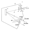
図1は、この発明の実施の形態に従う光学特性測定装置1の外観図を示す図である。
<Overall configuration of device>
FIG. 1 is an external view of optical
図1を参照して、この発明の実施の形態に従う光学特性測定装置1は、各種の発光体(以下、「対象物」とも称す。)のスペクトルを測定する。さらに、光学特性測定装置1は、この測定したスペクトルに基づいて、対象物の明るさや色合いといった光学特性を算出するようにしてもよい。なお、明るさとは、対象物の輝度や光度などを意味し、色合いとは、対象物の色度座標、主波長、刺激純度、および相関色温度などを意味する。本実施の形態に従う光学特性測定装置1は、発光ダイオード(LED:Light Emitting Diode)やフラットパネルディスプレイ(FPD:Flat Panel Display)などの測定に適用できる。
Referring to FIG. 1, optical
光学特性測定装置1は、測定器本体2と処理装置100とを含む。測定器本体2には、光ファイバ4を介して、光取出部6が接続されている。光取出部6によって取り入れられた対象物から放射された光(以下「測定光」とも称す。)は、光ファイバ4を介して測定器本体2へ導かれる。
The optical
測定器本体2は、後述するように、対象物から測定器本体2に入射する測定光を分光し、それに含まれる各波長成分の強度に応じた検出結果(信号強度)を処理装置100へ出力する。後述するように、測定器本体2は、その内部に、測定光を分光する分光器と、分光器によって分光された光を受光する光検出器とを含んでいる。特に、本実施の形態に従う光検出器は、分光器からの光の入射面より広い範囲の検出面を有している。また、処理装置100は、光検出器による検出結果を補正した上で出力する。より具体的には、処理装置100は、光検出器の検出面のうち、分光器からの光の入射面に対応する検出領域で検出されるスペクトルと、分光器からの光の入射面とは異なる検出領域で検出される信号強度とを独立して同時取得する。そして、処理装置100は、スペクトルの各成分値から信号強度に基づいて算出した補正値を減じることで、迷光に起因する誤差成分および光検出器に流れる暗電流によるオフセット成分を除去する。このような処理を行なうことで、対象物からの測定光のスペクトルをより短時間かつ高精度に測定することができる。
As will be described later, the measuring device
<測定器本体の構成>
図2は、この発明の実施の形態に従う測定器本体2の概略の機能ブロック図である。図2を参照して、測定器本体2は、シャッター21と、スリット22と、カットフィルタ23と、分光器24と、光検出器25とを含む。これらの構成要素は、筐体26内に収納される。筐体26の一部には、光取入口20が形成されている。光取入口20は、光ファイバ4と接続される。光ファイバ4によって導かれた測定光は、筐体26内に入射し、所定の光軸Axに沿って伝搬する。光取入口20の側から順に、この光軸Axに沿って、シャッター21、スリット22、カットフィルタ23、および分光器24が配置される。すなわち、測定光は、スリット22およびカットフィルタ23を通過した後に分光器24に入射する。
<Configuration of measuring instrument body>
FIG. 2 is a schematic functional block diagram of measuring instrument
シャッター21は、筐体26の外部から筐体26内に入射する光を遮断する。すなわち、シャッター21は、光検出器25による検出結果の校正基準となるスペクトル(いわゆる、「ダークスペクトル」)を取得するために、筐体26内に光が入射しない状態をつくる。一例として、シャッター21は、光軸Axに対して垂直方向に変位できるように構成されている。これにより、シャッター21が光軸Ax上に存在する場合(以下、「クローズ位置」とも称す。)には、筐体26内へ入射する光は遮断される。なお、筐体26内へ入射する光を遮断した状態で、光検出器25で検出されるダークスペクトルを測定する操作を、「ダーク測定」とも称す。一方、この「ダーク測定」と区別するために、通常の対象物についてのスペクトルを測定する操作を「通常測定」とも称す。
The
一方、シャッター21が光軸Axから離れた位置に位置する場合(以下、「オープン位置」とも称す。)には、測定光は、筐体26内に取込まれる。なお、図2には、シャッター21を筐体26内に設ける構成について例示したが、筐体26の外部に設けてもよい。また、測定光を遮断する機構については、いずれの種類の構成を採用してもよい。
On the other hand, when the
スリット22は、所定の検出分解能を実現するために、測定光の光束径(大きさ)を調整する。一例として、スリット22の各スリット幅は0.2mm〜0.05mm程度に設定される。そして、スリット22を通過後の測定光は、カットフィルタ23へ入射する。なお、カットフィルタ23は、スリット22を通過後の測定光のフォーカス位置とほぼ一致する位置に配置される。
The
カットフィルタ23は、筐体26に取込まれた測定光が分光器24に入射する光路である光軸Ax上に配置される。カットフィルタ23は、この測定光に含まれる成分波長のうち、所定の遮断波長αより短い波長の光を遮断する。すなわち、カットフィルタ23は、所定の遮断波長αより長い波長をもつ光のみを透過させる。後述するように、この遮断波長αは、分光器24の分光特性の下限値(波長fmin)と一致させることが好ましい。
The
分光器24は、光軸Ax上に配置され、光軸Ax上に沿って入射する測定光を成分波長に分光する。分光器24が分光することで生じる光は、光検出器25へ導かれる。分光器24は、一例として、ブレーズドホログラフィック型と呼ばれる凹面回折格子(グレーティング)からなる。この凹面回折格子は、入射する測定光を所定の波長間隔の回折光として、対応する方向に反射する。そのため、分光器24で分光された光(回折光)は、空間的な広がりをもって、光検出器25へ向けて放射される。
The
なお、分光器24としては、上述したブレーズドホログラフィック型の凹面回折格子に代えて、フラットフォーカス型の凹面回折格子といった任意の回折格子を採用することができる。
As the
光検出器25は、分光器24によって分光された測定光(回折光)を受光する。そして、光検出器25は、受光した測定光に含まれる各成分波長の強度を検出する。この光検出器25によって検出された強度は、各成分波長に対応付けられている。そのため、光検出器25からの検出信号は、測定光のスペクトルに相当する。光検出器25は、代表的にフォトダイオードなどの複数の検出素子を、アレイ状に配置したフォトダイオードアレイ(PDA:Photo Diode Array)からなる。あるいは、フォトダイオードなどの複数の検出素子を、マトリックス状に配置されたCCD(Charged Coupled Device)であってもよい。一例として、光検出器25は、380nm〜980nmの範囲で512個(チャンネル)の成分波長の強度を示す信号を出力可能に構成される。また、光検出器25は、検出された光強度の信号をデジタル信号として出力するためのA/D(Analog to Digital)変換器や周辺回路を含む。
The
<補正処理の概要>
以下、図1、図3および図4を参照して、本実施の形態に従う光学特性測定装置1における補正処理について説明する。光検出器25からの検出結果は、(1)測定光の測定すべきスペクトル、(2)筐体内部で発生する迷光に起因する誤差成分、(3)光検出器25に流れる暗電流によるオフセット成分、および、(4)その他の誤差成分、を含む。
<Outline of correction processing>
Hereinafter, with reference to FIG. 1, FIG. 3, and FIG. 4, correction processing in optical
迷光とは、筐体26内部で乱反射した光、分光器24表面で拡散反射した光、および分光器24で生じた測定次数以外の次数をもつ光を総称するものである。
The stray light is a generic term for light diffusely reflected inside the
また、光検出器25は、CCDなどの半導体デバイスからなり、このような半導体デバイスを駆動する際には暗電流が流れる。この暗電流によって、光検出器25からの検出結果には、オフセット成分が生じ得る。また、この暗電流の大きさは、周囲温度の影響を受けやすく、測定環境に起因して時間的に変動し得る。
The
そこで、本実施の形態に従う光学特性測定装置1では、光検出器25の検出面に、分光器24からの回折光が入射する領域と、当該回折光が入射しない領域とを設ける。そして、処理装置100が、回折光が入射する領域で検出された検出結果を、回折光が入射しない領域で検出された検出結果を用いて補正する。すなわち、通常測定の実行毎に、このような補正を行なうことで、迷光による影響および暗電流によるオフセット成分を動的に補正することができる。そのため、迷光による影響および/または暗電流によるオフセット成分が時間的に変動した場合であっても、有効に補正できる。
Therefore, in the optical
図3は、この発明の実施の形態に従う光検出器25の検出面を示す模式図である。図3を参照して、光検出器25(図2)は、入射する測定光のうち、波長fminから波長fmaxの範囲の成分波長を分光器24に導くように光学設計されているものとする。
FIG. 3 is a schematic diagram showing a detection surface of
ここで、カットフィルタ23の遮断波長αは、波長fminと一致するように設定されているものとする。この場合、波長fmin(遮断波長α)より短い成分波長は、分光器24に入射しないことになる。そのため、光検出器25においても、波長fmin(遮断波長α)より短い成分波長は入射しない。
Here, it is assumed that the cutoff wavelength α of the
そこで、光検出器25の検出面のうち、波長fminから波長fmaxの範囲(以下、「測定波長域」とも称す。)に対応する領域を検出領域25aに設定する。すなわち、検出領域25aは、分光器24からの光の入射面に対応する領域である。また、検出領域25aに引き続く短波長側に所定範囲(以下、「補正波長域」とも称す。)の補正領域25bに設定する。なお、波長fminより短波長側の全範囲を補正領域25bに設定してもよいが、測定光の影響を避けるためには、検出領域25aと補正領域25bとの間を所定の波長幅だけ離すことが好ましい。
Therefore, an area corresponding to a range from the wavelength f min to the wavelength f max (hereinafter also referred to as “measurement wavelength area”) on the detection surface of the
再度図1を参照して、筐体26の内部で発生する迷光は、一様に拡散しているとみなすことができる。そのため、光検出器25の検出面に入射する迷光は、ほぼ均一と見なすことができる。すなわち、検出領域25aおよび補正領域25bを構成する複数の検出素子の各々に入射する迷光の強度は、互いにほぼ同一である。
Referring again to FIG. 1, stray light generated inside the
また、検出領域25aおよび補正領域25bは、共通の光検出器25上に設けられる。そのため、検出領域25aおよび補正領域25bによる検出結果に含まれる暗電流によるオフセット成分についても、ほぼ一様とみなすことができる。
The
以上のような考察によれば、光検出器25からは、図4に示すような検出結果が出力される。 According to the above consideration, a detection result as shown in FIG.
図4は、この発明の実施の形態に従う光学特性測定装置1の光検出器25から出力される検出結果の一例を示す概念図である。
FIG. 4 is a conceptual diagram showing an example of a detection result output from the
図4を参照して、光検出器25から出力される検出結果は、迷光に起因する誤差成分40を含む。この誤差成分40は、検出可能な波長範囲に亘って一様の信号強度をもつとみなすことができる。また、検出結果は、光検出器25に含まれる複数の検出素子を流れる暗電流によるオフセット成分50を含む。このオフセット成分50は、周囲温度に依存するとともに、時間的にも変動する。
Referring to FIG. 4, the detection result output from
また、測定波長域では、測定光のスペクトルに応じた信号強度が現れる。一方、補正波長域では、測定光に応じた信号強度は現れない。 In the measurement wavelength range, signal intensity corresponding to the spectrum of measurement light appears. On the other hand, in the correction wavelength range, the signal intensity corresponding to the measurement light does not appear.
そのため、検出領域25a(図3)で検出された測定スペクトルの各成分値から補正領域25b(図3)で検出された信号強度に基づいて算出される補正値を減じることで、迷光に起因する誤差成分および暗電流によるオフセット成分を取り除くことができる。その結果、測定光の本来のスペクトルを取得することができる。なお、複数の検出素子を含むように補正領域25bを設定することが好ましく、この場合には、複数の信号強度が検出
できる。そこで、補正値としては、それぞれの検出素子で検出された信号強度の代表値(典型的には、平均値あるいは中間値)を用いることが好ましい。
Therefore, the correction value calculated based on the signal intensity detected in the
また、本実施の形態に従う光学特性測定装置では、筐体26内に光が入射しない状態において光検出器25で検出されるダークスペクトルに対しても、上述したように、迷光に起因する誤差成分および暗電流によるオフセットを取り除く補正をした上で、基準値として格納する。この基準値として格納する補正後のダークスペクトルは、(1)測定光の測定値、(2)筐体内部で発生する迷光に起因する誤差成分、および(3)光検出器25に流れる暗電流によるオフセット成分を含まない。すなわち、この補正後のダークスペクトルは、検出素子のバラツキなどの各装置固有の誤差要因を反映したものとなる。
Further, in the optical characteristic measurement apparatus according to the present embodiment, as described above, the error component caused by stray light is also detected for the dark spectrum detected by the
したがって、各測定において、光検出器25で検出された測定スペクトルから、補正領域25b(図3)で検出された信号強度、および補正後のダークスペクトルをそれぞれ減じることで、測定光のスペクトルを高精度に測定することができる。また、毎回の通常測定においては、迷光による誤差成分および/または暗電流によるオフセット成分を測定するためだけに、シャッター21を開閉する必要がないので、測定に要する時間を短縮することができる。
Therefore, in each measurement, the spectrum of the measurement light is increased by subtracting the signal intensity detected in the
<処理装置の構成>
再度図1を参照して、処理装置100は、代表的にコンピュータによって構成される。より具体的には、処理装置100は、FD(Flexible Disk)駆動装置111およびCD−ROM(Compact Disk-Read Only Memory)駆動装置113を搭載するコンピュータ本体101と、モニタ102と、キーボード103と、マウス104とからなる。そして、コンピュータ本体101が予め格納されたプログラムを実行することで、上述した補正処理を提供する。
<Configuration of processing device>
Referring to FIG. 1 again, the
図5は、この発明の実施の形態に従う処理装置100のハードウェア構成を示す概略構成図である。図5を参照して、コンピュータ本体101は、図1に示すFD駆動装置111およびCD−ROM駆動装置113に加えて、相互にバスで接続された、CPU(Central Processing Unit)105と、メモリ106と、固定ディスク107と、通信インターフェイス部(I/F)109とを含む。
FIG. 5 is a schematic configuration diagram showing a hardware configuration of
FD駆動装置111にはFD112が装着可能であり、CD−ROM駆動装置113にはCD−ROM114が装着可能である。本実施の形態に従う処理装置100は、CPU105がメモリ106などのコンピュータハードウェアを用いて、プログラムを実行することで実現される。一般的に、このようなプログラムは、FD112やCD−ROM114などの記録媒体に格納されて、あるいはネットワークなどを介して流通する。そして、このようなプログラムは、FD駆動装置111やCD−ROM駆動装置113などにより記録媒体から読取られて、記憶装置である固定ディスク107に一旦格納される。さらに、固定ディスク107からメモリ106に読出されて、CPU105により実行される。
An
CPU105は、プログラムされた命令を順次実行することで、各種の演算を実施する演算処理部である。メモリ106は、CPU105でのプログラム実行に応じて、各種の
情報を一時的に記憶する。
The
通信インターフェイス部109は、コンピュータ本体101と測定器本体2(図1)との間のデータ通信を仲介するための装置であり、測定器本体2から送信された測定データを示す電気信号を受信してCPU105が処理可能なデータ形式に変換するとともに、CPU105が出力した指令などを電気信号に変換して測定器本体2へ送出する。
The
コンピュータ本体101に接続されるモニタ102は、CPU105によって算出される対象物の明るさや色合いなどの算出結果を表示するための表示装置であって、一例としてLCD(Liquid Crystal Display)やCRT(Cathode Ray Tube)などから構成される。
A
マウス104は、クリックやスライドなどの動作に応じたユーザからの指令を受付ける。キーボード103は、入力されるキーに応じたユーザからの指令を受付ける。
The
また、コンピュータ本体101には、必要に応じて、プリンタなどの他の出力装置が接続されてもよい。
In addition, other output devices such as a printer may be connected to the computer
<測定手順>
本実施の形態に従う光学特性測定装置1における補正処理についての理解をより容易にするために、まず、本発明の関連技術に係る測定手順について説明する。
<Measurement procedure>
In order to make it easier to understand the correction process in the optical
(1.関連技術に係る処理手順)
図6は、この発明の関連技術に係る光学特性測定装置における測定手順を示すフローチャートである。なお、図6では、通常測定毎にダーク測定を実行する場合の処理手順を示す。
(1. Processing procedures related to related technology)
FIG. 6 is a flowchart showing a measurement procedure in the optical characteristic measuring apparatus according to the related art of the present invention. FIG. 6 shows a processing procedure when performing dark measurement for each normal measurement.
図6を参照して、処理装置は、測定開始指令を与えられたか否かを判断する(ステップS300)。測定開始指令が与えられていない場合(ステップS300においてNOの場合)には、測定開始指令が与えられるまで待つ。なお、測定開始指令が与えられる前に、対象物から放射される光が光取出部に取り込まれるように、対象物および/または光取出部の位置合わせが実行される。 Referring to FIG. 6, the processing apparatus determines whether or not a measurement start command is given (step S300). If a measurement start command is not given (NO in step S300), the process waits until a measurement start command is given. Note that before the measurement start command is given, alignment of the object and / or the light extraction unit is executed so that light emitted from the object is taken into the light extraction unit.
一方、測定開始指令が与えられた場合(ステップS300においてYESの場合)には、まず、ステップS302およびステップS304に示すダーク測定が実行される。具体的には、処理装置がシャッターをクローズ位置に駆動する(ステップS302)。すなわち、筐体内への光の入射が遮断された状態が形成される。続いて、処理装置は、光検出器により検出されたスペクトルをダークスペクトルとして取得する(ステップS304)。 On the other hand, when a measurement start command is given (YES in step S300), dark measurement shown in steps S302 and S304 is first executed. Specifically, the processing device drives the shutter to the closed position (step S302). That is, a state in which the incidence of light into the housing is blocked is formed. Subsequently, the processing apparatus acquires the spectrum detected by the photodetector as a dark spectrum (step S304).
続いて、ステップS306〜S310に示す通常測定が実行される。具体的には、処理装置がシャッターをオープン位置に駆動する(ステップS306)。すなわち、測定光が筐体内へ取り込まれる。続いて、処理装置は、光検出器により検出されたスペクトルを測定スペクトルとして取得する(ステップS308)。さらに、処理装置は、ステップS308において取得した測定スペクトルの各成分値からステップS304において取得したダークスペクトルの対応する成分値を減じることで、出力スペクトルを算出する(ステップS310)。この出力スペクトルが検出結果として出力される。 Subsequently, normal measurement shown in steps S306 to S310 is performed. Specifically, the processing device drives the shutter to the open position (step S306). That is, the measurement light is taken into the housing. Subsequently, the processing apparatus acquires a spectrum detected by the photodetector as a measurement spectrum (step S308). Further, the processing device calculates an output spectrum by subtracting the corresponding component value of the dark spectrum acquired in step S304 from each component value of the measurement spectrum acquired in step S308 (step S310). This output spectrum is output as a detection result.
その後、測定中止指令が与えられたか否かを判断する(ステップS312)。測定中止指令が与えられていない場合(ステップS312においてNOの場合)には、処理はステップS300に戻る。 Thereafter, it is determined whether or not a measurement stop command is given (step S312). If no measurement stop command is given (NO in step S312), the process returns to step S300.
一方、測定中止指令が与えられた場合(ステップS312においてYESの場合)には、処理は終了する。 On the other hand, if a measurement stop command is given (YES in step S312), the process ends.
(2.本実施の形態に従う処理手順)
本実施の形態に従う光学特性測定装置1では、一連の通常測定に先立って、ダーク測定が実行される。そのダーク測定の実行後、対象物についての通常測定が実行される。以下、図7および図8を参照して、その処理手順について説明する。
(2. Processing procedure according to the present embodiment)
In optical
図7は、この発明の実施の形態に従う光学特性測定装置1におけるダーク測定の処理手順を示すフローチャートである。図8は、この発明の実施の形態に従う光学特性測定装置1における通常測定の処理手順を示すフローチャートである。
FIG. 7 is a flowchart showing a dark measurement processing procedure in optical
図7を参照して、処理装置100は、ダーク測定開始指令を与えられたか否かを判断する(ステップS100)。ダーク測定開始指令が与えられていない場合(ステップS100においてNOの場合)には、ダーク測定開始指令が与えられるまで待つ。
Referring to FIG. 7,
一方、ダーク測定開始指令が与えられた場合(ステップS100においてYESの場合)には、処理装置100は、シャッター21をクローズ位置に駆動する(ステップS102)。すなわち、筐体26内への光の入射が遮断された状態が形成される。続いて、処理装置100は、光検出器25の検出領域25aで検出されたスペクトル(ダークスペクトル)と、光検出器25の補正領域25bで検出された信号強度とを取得する(ステップS104)。続いて、処理装置100は、補正領域25bで検出された信号強度に基づいて、補正値を算出する(ステップS106)。より具体的には、補正領域25bで検出された複数の信号強度の平均値が補正値として算出される。
On the other hand, when the dark measurement start command is given (YES in step S100),
さらに、処理装置100は、ステップS104において取得された検出領域25aで検出されたダークスペクトルに含まれる各成分値(信号強度)から、ステップS106において算出した補正値を(一律に)減じることで補正ダークスペクトルを算出する(ステップS108)。すなわち、処理装置100は、補正領域25bで検出された信号強度に基づいて算出される補正値で、ダークスペクトルを補正することで補正ダークスペクトルを算出する。さらに、処理装置100は、ステップS108において算出した補正ダークスペクトルを格納する(ステップS110)。
Furthermore, the
その後、処理装置100は、シャッター21をオープン位置に駆動する(ステップS112)。これにより、光学特性測定装置1は測定状態になる。そして、ダーク測定は終了する。
Thereafter, the
次に、図8を参照して、処理装置100は、測定開始指令を与えられたか否かを判断する(ステップS200)。測定開始指令が与えられていない場合(ステップS200においてNOの場合)には、測定開始指令が与えられるまで待つ。なお、測定開始指令が与えられる前に、対象物から放射される光が光取出部6に取り込まれるように、対象物および/または光取出部6の位置合わせが実行される。
Next, with reference to FIG. 8,
一方、測定開始指令が与えられた場合(ステップS200においてYESの場合)には、処理装置100は、光検出器25の検出領域25aで検出された測定スペクトルと、光検出器25の補正領域25bで検出された信号強度とを取得する(ステップS202)。なお、先に実行されたダーク測定の実行後において、シャッター21がオープン位置に駆動されるので、光学特性測定装置1は、遮断部に相当するシャッター21を開放した測定状態となっている。
On the other hand, when a measurement start command is given (in the case of YES in step S200), the
続いて、処理装置100は、補正領域25bで検出された信号強度に基づいて、補正値を算出する(ステップS204)。より具体的には、補正領域25bで検出された複数の信号強度の平均値が補正値として算出される。
Subsequently, the
さらに、処理装置100は、ステップS202において取得された検出領域25aで検出された測定スペクトルに含まれる各成分値(信号強度)から、ステップS204において算出した補正値を(一律に)減じることで補正測定スペクトルを算出する(ステップS206)。すなわち、処理装置100は、補正領域25bで検出された信号強度に基づいて算出される補正値で、測定スペクトルを補正することで補正測定スペクトルを算出する。さらに、処理装置100は、ステップS206において算出した補正測定スペクトルの各成分値から、先に実行したダーク測定(ステップS108)において算出した補正ダークスペクトルの対応する成分値を減じることで、出力スペクトルを算出する(ステップS208)。この出力スペクトルが検出結果として出力される。
Further, the
その後、測定中止指令が与えられたか否かを判断する(ステップS210)。測定中止指令が与えられていない場合(ステップS210においてNOの場合)には、処理はステップS200に戻る。 Thereafter, it is determined whether or not a measurement stop command is given (step S210). If the measurement stop command is not given (NO in step S210), the process returns to step S200.
一方、測定中止指令が与えられた場合(ステップS210においてYESの場合)には、処理は終了する。 On the other hand, if a measurement stop command is given (YES in step S210), the process ends.
以上のように、本実施の形態に従う光学特性測定装置1においては、各通常測定においてダーク測定を行なう必要がない。そのため、通常測定に要する時間を短縮することができる。
As described above, in optical
<制御構造>
図9は、この発明の実施の形態に従う光学特性測定装置1の処理装置100における制御構造を示す概略図である。
<Control structure>
FIG. 9 is a schematic diagram showing a control structure in
図9を参照して、本実施の形態に従う処理装置100は、バッファ202,212,220,240と、補正値算出部204と、セレクタ214,218,222,226,232と、減算部216,224と、メモリ230とを含む。なお、図9には、一例として、測定波長域に対応する検出領域25a(図3)がN個の検出素子を有し、測定波長域に対応する補正領域25bが4個の検出素子を有する場合に対応する制御構造を示す。
Referring to FIG. 9,
光検出器25の検出領域25aで検出された値(各波長の信号強度)は、バッファ212に一時的に格納される。また、光検出器25の補正領域25bで検出された値(信号強度)は、バッファ202に一時的に格納される。バッファ212は、検出領域25aに含まれる検出素子の数に対応して、少なくとも区画されたN個の領域(1ch,2ch,…,Nch)をもつ。また、バッファ212は、補正領域25bに含まれる検出素子の数に対応して、少なくとも区画された4個の領域(Ach,Bch,Cch,Dch)をもつ。なお、バッファ202および212に格納されるデータは、光検出器25の検出周期(たとえば、数msec〜数10msec)で順次更新される。また、チャンネル(ch)は、光検出器25で検出される波長に対応付けられている。
The value (signal intensity of each wavelength) detected in the
補正値算出部204は、バッファ202に格納される補正領域25bで検出された信号強度に基づいて、補正値ΔMを算出する。具体的には、補正値算出部204は、バッファ202に格納されている4個の信号強度の平均値(もしくは、中間値)を補正値ΔMとして算出する。
The correction
セレクタ214および減算部216は、検出領域25aで検出されたダークスペクトルもしくは測定スペクトルの各成分値から補正値ΔMを減じる。より具体的には、セレクタ214は、クロック信号CLOCKに従って、バッファ212に格納されている各波長(チャンネル)の信号強度を順次読出して、減算部216へ出力する。減算部216は、セレクタ214から入力される信号強度から補正値ΔMを減じて、その結果をセレクタ218へ出力する。したがって、減算部216からは、バッファ212に格納される各波長の信号強度に対して、補正値ΔMが減じられた結果が出力される。
The
セレクタ218は、光学特性測定装置1の状態(ダーク測定あるいは通常測定)およびシャッター21の開閉状態などに応じて、取得されたスペクトルがダークスペクトルであるか、あるいは測定スペクトルであるかを判断する。そして、セレクタ218は、セレクタ214と共通のクロック信号CLOCKに従って、減算部216から出力される結果値をバッファ220およびメモリ230のいずれか一方に順次格納する。
The
バッファ220は、補正測定スペクトルを一時的に格納し、メモリ230は、補正ダークスペクトルを不揮発的に格納する。なお、補正ダークスペクトルは、ダーク測定の完了後、新たなダーク測定が実行されるまでの間、通常測定において繰り返し用いられるので、不揮発的に格納されることが好ましい。
The
すなわち、ダーク測定時には、バッファ212にダークスペクトルを示す各波長の信号強度が格納される。この場合には、セレクタ218は、減算部216によって一律に補正値ΔMを減じることで得られる結果を、メモリ230に順次格納する。一方、通常測定時には、バッファ212に測定スペクトルを示す各波長の信号強度が格納される。この場合には、セレクタ218は、減算部216によって一律に補正値ΔMを減じることで得られる結果を、バッファ220に順次格納する。すなわち、バッファ212に格納されるスペクトルの各波長の信号強度をA(i){但し、1≦i≦n}とすると、バッファ220または230に格納される補正後のスペクトルB(i)は、以下のように表わすことができる。
That is, at the time of dark measurement, the signal intensity of each wavelength indicating a dark spectrum is stored in the
B(i)=A(i)−ΔM{但し、1≦i≦n}
また、セレクタ214とセレクタ218とは、クロック信号CLOCKに従って同期する。そのため、たとえば、バッファ212の1chから読出された信号強度は、バッファ220の1chまたはメモリ230の1chに格納される。
B (i) = A (i) −ΔM {where 1 ≦ i ≦ n}
The
セレクタ222,226,232および減算部224は、補正測定スペクトルの各成分値から補正ダークスペクトルの対応する成分値を減じて出力スペクトルを算出する。より具体的には、セレクタ222は、クロック信号CLOCKに従って、バッファ220に格納されている補正測定スペクトルの各波長(チャンネル)の信号強度を順次読出して、減算部224へ出力する。同様に、セレクタ232は、セレクタ222と共通のクロック信号CLOCKに従って、メモリ230に格納されている補正ダークスペクトルの各波長(チャンネル)の信号強度を順次読出して、減算部224へ出力する。減算部224は、セレクタ222から入力される信号強度から、セレクタ232から入力される信号強度を減じて、その結果をセレクタ226へ出力する。また、セレクタ222とセレクタ232とは、クロック信号CLOCKに従って同期する。
The
セレクタ226は、セレクタ222および232と共通のクロック信号CLOCKに従って、減算部224から出力される結果値をバッファ240に順次格納する。
The
したがって、バッファ240には、補正測定スペクトルの各成分値から補正ダークスペクトルの対応する成分値を減じた結果が格納される。すなわち、バッファ220に格納される補正測定スペクトルの各波長の信号強度をS(i){但し、1≦i≦n}とし、メモリ230に格納される補正ダークスペクトルの各波長の信号強度をD(i){但し、1≦i≦n}とすると、バッファ240に格納される出力スペクトルM(i)は、以下のように表わすことができる。
Therefore, the
M(i)=S(i)−D(i){但し、1≦i≦n}
そして、このバッファ240に格納される出力スペクトルが測定結果として出力される。
M (i) = S (i) −D (i) {where 1 ≦ i ≦ n}
The output spectrum stored in the
図9に示す制御構造は、典型的に、CPU105(図5)が、固定ディスク107(図5)などに格納されているプログラムをメモリ106(図5)に展開して実行することで提供される。なお、図9に示す制御構造の一部もしくは全部をハードウェアによって提供してもよい。 The control structure shown in FIG. 9 is typically provided by the CPU 105 (FIG. 5) developing a program stored in the fixed disk 107 (FIG. 5) or the like in the memory 106 (FIG. 5) and executing it. The Note that part or all of the control structure shown in FIG. 9 may be provided by hardware.
また、図9には、波長毎の信号強度について、直列的に演算処理を採用した構成について例示したが、スペクトル同士を一括して減算するといった並行的な演算処理を採用してもよい。さらに、上述のような算術演算処理が実現できるのであれば、いずれの演算処理を採用してもよい。 In addition, although FIG. 9 illustrates the configuration in which arithmetic processing is adopted in series for the signal intensity for each wavelength, parallel arithmetic processing such as subtracting spectra together may be employed. Furthermore, any arithmetic processing may be adopted as long as the arithmetic arithmetic processing as described above can be realized.
<測定例>
上述した本実施の形態に従う光学特性測定装置1の迷光などに起因する誤差に対する低減効果について、実際に測定した結果の一例を以下に示す。
<Measurement example>
An example of the result of actual measurement is shown below for the effect of reducing the error caused by stray light or the like of the optical
迷光の影響を評価する方法として、日本工業規格JIS Z8724:1997「色の測定方法−光源色」には、分光測光器の「迷光」の性能の条件が規定されている。このJIS規格に従って、本実施の形態に従う補正処理に係る迷光による誤差の排除性能について評価を行った。また、比較対象として、本実施の形態に従う補正処理を適用しなかった場合の測定結果についても示す。なお、補正処理を適用しない場合であっても、上述の図6に示す測定手順と同様に、光検出器25の検出値から暗電流によるオフセット成分を除く補正処理は実行した。
As a method for evaluating the influence of stray light, the Japanese Industrial Standard JIS Z8724: 1997 “Color Measurement Method—Light Source Color” defines conditions for the performance of “stray light” of a spectrophotometer. In accordance with this JIS standard, the error elimination performance due to stray light related to the correction processing according to the present embodiment was evaluated. In addition, as a comparison target, a measurement result when the correction process according to the present embodiment is not applied is also shown. Even when the correction process is not applied, the correction process for removing the offset component due to the dark current from the detection value of the
上記JIS規格においては、測定光の光源としてタングステン電球を用いて迷光を評価することが規定されている。その具体的な手順としては、まず、タングステン電球から放射された光を入射した場合における光検出器からの出力(レファレンス値)を取得する。次に、透過限界波長がそれぞれ、500±5(nm),560±5(nm),660±5(nm)であるシャープカットフィルタを、タングステン電流から放射された光の入射光路に挿入した場合に光検出器からの出力をそれぞれ取得する。なお、評価される出力は、それぞれ、450(nm),500(nm),600(nm)における値である。最終的に、それぞれの出力のレファレンス値に対する比率を、迷光を評価する値(迷光率)として算出する。 In the JIS standard, it is defined that stray light is evaluated using a tungsten light bulb as a light source of measurement light. As a specific procedure, first, an output (reference value) from a photodetector when light emitted from a tungsten bulb is incident is acquired. Next, when a sharp cut filter having transmission limit wavelengths of 500 ± 5 (nm), 560 ± 5 (nm), and 660 ± 5 (nm) is inserted in the incident light path of the light emitted from the tungsten current, respectively The output from the photodetector is obtained respectively. The output to be evaluated is a value at 450 (nm), 500 (nm), and 600 (nm), respectively. Finally, the ratio of each output to the reference value is calculated as a value (stray light rate) for evaluating stray light.
なお、本測定例においては、透過限界波長がそれぞれ、495(nm),550(nm),665(nm)の3つのシャープカットフィルタを用いて評価した。 In this measurement example, evaluation was performed using three sharp cut filters having transmission limit wavelengths of 495 (nm), 550 (nm), and 665 (nm), respectively.
図10は、この発明の実施の形態に従う光学特性測定装置1についての迷光評価の一例を示す図である。図11は、図10に示すスペクトルの部分的な拡大図を示す。
FIG. 10 is a diagram showing an example of stray light evaluation for optical
図10には、何らのカットフィルタも挿入していない状態(レファレンス)と、それぞれのシャープカットフィルタを挿入した状態とについての測定例を示す。図10に示すように、それぞれシャープカットフィルタを挿入することで、対応する透過限界波長より短い波長が遮断されていることがわかる。 FIG. 10 shows measurement examples of a state in which no cut filter is inserted (reference) and a state in which each sharp cut filter is inserted. As shown in FIG. 10, it can be seen that by inserting a sharp cut filter, wavelengths shorter than the corresponding transmission limit wavelength are blocked.
図11(a)には、透過限界波長が495(nm)であるシャープカットフィルタを挿入した場合において、補正処理の有無による、450(nm)近傍の信号強度の違いを示す。また、図11(b)には、透過限界波長が550(nm)であるシャープカットフィルタを挿入した場合において、補正処理の有無による、550(nm)近傍の信号強度の違いを示す。また、図11(c)には、透過限界波長が665(nm)であるシャープカットフィルタを挿入した場合において、補正処理の有無による、600(nm)近傍の信号強度の違いを示す。 FIG. 11A shows the difference in signal intensity near 450 (nm) depending on the presence or absence of correction processing when a sharp cut filter having a transmission limit wavelength of 495 (nm) is inserted. FIG. 11B shows a difference in signal intensity in the vicinity of 550 (nm) depending on whether or not correction processing is performed when a sharp cut filter having a transmission limit wavelength of 550 (nm) is inserted. FIG. 11C shows a difference in signal intensity in the vicinity of 600 nm depending on the presence or absence of correction processing when a sharp cut filter having a transmission limit wavelength of 665 nm is inserted.
いずれに示す例においても、本実施の形態に従う補正処理を適用することで、出力がゼロ値に近づいていることが分かる。 In any of the examples, it can be seen that the output approaches the zero value by applying the correction processing according to the present embodiment.
以上のような結果をまとめると、以下に示す表のようになる。なお、表中における「低減率」は、補正処理を適用しない場合の迷光率に対する補正処理が適用された場合の迷光率の大きさの比を示す。 The above results are summarized as shown in the table below. The “reduction rate” in the table indicates the ratio of the magnitude of the stray light rate when the correction process is applied to the stray light rate when the correction process is not applied.

上表に示されるように、本実施の形態に従う補正処理を適用することで、迷光率を半分以下に低減できることがわかる。 As shown in the table above, it can be seen that the stray light rate can be reduced to half or less by applying the correction processing according to the present embodiment.
<本実施の形態における作用効果>
この発明の実施の形態によれば、光検出器25の検出面に、分光器24で分光された光が入射する領域(検出領域25a)と、分光器24で分光された光が入射しない領域(補正領域25b)が設けられる。測定時において、検出領域25aおよび補正領域25bからそれぞれスペクトルおよび強度値が同時に取得される。そして、補正領域25bで検出された信号強度に基づいて補正値が算出される。さらに、検出領域25aで検出されたスペクトルの各成分値(各波長の信号強度)からこの算出された補正値が減じられることで、補正後のスペクトルが算出される。
<Operational effects in the present embodiment>
According to the embodiment of the present invention, a region (
上述のような補正値は、筐体内部で発生する迷光に起因する誤差成分と、光検出器25に流れる暗電流によるオフセット成分とを反映した値となる。そのため、検出領域25aで検出されたスペクトルをこのような補正値で補正することにより、本来の測定光のスペクトルを正確に取得することができる。
The correction value as described above is a value reflecting an error component due to stray light generated inside the housing and an offset component due to dark current flowing through the
また、この発明の実施の形態によれば、同一の光検出器25の上に設けられた検出領域25aおよび補正領域25bから、それぞれスペクトルおよび強度値が同時に取得される。そのため、筐体内部で発生する迷光に起因する誤差成分、および/または、光検出器25に流れる暗電流によるオフセット成分が時間的に変動する場合であっても、これらの誤差成分を確実に取り除くことができる。すなわち、周囲温度などの環境要因による外乱に対する誤差をより確実に取り除くことができる。
Further, according to the embodiment of the present invention, the spectrum and the intensity value are simultaneously acquired from the
さらに、筐体内部で発生する迷光に起因する誤差成分、および/または、光検出器25に流れる暗電流によるオフセット成分を取得するために、ダーク測定を行なう必要がない。そのため、測定毎にシャッターを開閉する必要がないので、測定に要する時間を短縮することができる。
Further, it is not necessary to perform dark measurement in order to acquire an error component due to stray light generated inside the housing and / or an offset component due to dark current flowing in the
また、この発明の実施の形態によれば、上述のような補正を行なった後のダークスペクトル(補正ダークスペクトル)を用いてさらに補正を行なう。そのため、測定結果として出力されるスペクトルは、迷光に起因する誤差成分および暗電流によるオフセット成分以外の誤差成分が取り除かれたものとなる。そのため、対象物のスペクトルをより高精度に測定することができる。 Further, according to the embodiment of the present invention, the correction is further performed using the dark spectrum (corrected dark spectrum) after the correction as described above. Therefore, the spectrum output as the measurement result is obtained by removing error components other than the error component due to stray light and the offset component due to dark current. Therefore, the spectrum of the object can be measured with higher accuracy.
[変形例1]
上述の実施の形態においては、通常測定前に、ダーク測定を行なってダークスペクトルおよび補正ダークスペクトルを予め取得する構成について例示した。本変形例では、このダーク測定を省略できる構成について例示する。
[Modification 1]
In the above-described embodiment, the configuration in which the dark spectrum and the corrected dark spectrum are acquired in advance by performing the dark measurement before the normal measurement is illustrated. In this modification, a configuration that can omit this dark measurement is illustrated.
<装置全体構成>
図12は、この発明の実施の形態の変形例1に従う測定器本体2#の概略の機能ブロック図である。図12に示す測定器本体2#は、図2に示す測定器本体2からシャッター21を取除いたものに相当する。測定器本体2#のその他の部位は、測定器本体2と同様であるので、詳細な説明は繰返さない。
<Overall configuration of device>
FIG. 12 is a schematic functional block diagram of measuring instrument
<ダークスペクトルの特性>
まず、光検出器25のダークスペクトルの特性について実際に測定した結果について例示する。
<Characteristics of dark spectrum>
First, the result of actual measurement of the characteristics of the dark spectrum of the
(1.温度依存性)
図13は、この発明の実施の形態に従うダーク測定結果の温度依存性を示す図である。図13に示す測定結果は、恒温層内に測定器本体を配置し、恒温層内の温度を変化させた場合に得られた出力の時間的変化を示す。より具体的には、恒温層内の温度を当初10℃に設定しておき、測定開始から30分経過後に、恒温層内の温度を20℃に変更した。また、図13には、ダークスペクトル(補正処理無)および補正ダークスペクトル(補正処理有)の両方の測定結果を示す。なお、光検出器25の露光時間は20secとした。ダークスペクトルおよび補正ダークスペクトルのスペクトル幅は250〜750nmとし、これらのスペクトルにおける50nm毎の出力値の平均値を測定結果とした。
(1. Temperature dependence)
FIG. 13 shows the temperature dependence of the dark measurement result according to the embodiment of the present invention. The measurement result shown in FIG. 13 shows a temporal change in output obtained when the measuring device main body is arranged in the constant temperature layer and the temperature in the constant temperature layer is changed. More specifically, the temperature in the constant temperature layer was initially set to 10 ° C., and after 30 minutes from the start of measurement, the temperature in the constant temperature layer was changed to 20 ° C. FIG. 13 shows the measurement results of both the dark spectrum (without correction processing) and the corrected dark spectrum (with correction processing). The exposure time of the
図13に示すように、ダークスペクトル(補正処理無)については、周囲温度変化の影響を受けて出力値が変動していることがわかる。これに対して、補正ダークスペクトル(補正処理有)については、周囲温度変化の影響をほとんど受けていないことがわかる。 As shown in FIG. 13, it can be seen that the output value of the dark spectrum (without correction processing) fluctuates due to the influence of the ambient temperature change. On the other hand, it can be seen that the corrected dark spectrum (with correction processing) is hardly affected by the ambient temperature change.
図14は、この発明の実施の形態に従うダークスペクトルの温度依存性を示す測定結果である。図15は、図14に示すダークスペクトルから得られるダークパターンを示す図である。 FIG. 14 shows the measurement results indicating the temperature dependence of the dark spectrum according to the embodiment of the present invention. FIG. 15 is a diagram showing a dark pattern obtained from the dark spectrum shown in FIG.
図14(a)には、周囲温度が10℃の場合のダークスペクトルを示し、図14(b)には、周囲温度が20℃の場合のダークスペクトルを示し、図14(c)には、周囲温度が30℃の場合のダークスペクトルを示す。なお、光検出器25の露光時間は、図13と同じく20secとした。
FIG. 14A shows a dark spectrum when the ambient temperature is 10 ° C., FIG. 14B shows a dark spectrum when the ambient temperature is 20 ° C., and FIG. A dark spectrum in the case where the ambient temperature is 30 ° C. is shown. Note that the exposure time of the
図14(a)〜図14(c)に示すダークスペクトルを比較すると、同一の波長に対応する振幅の絶対値が異なっていることがわかる。すなわち、ダークスペクトルは、周囲温度によりその特性が影響を受けていることがわかる。 Comparing the dark spectra shown in FIGS. 14A to 14C, it can be seen that the absolute values of the amplitudes corresponding to the same wavelength are different. That is, it can be seen that the characteristics of the dark spectrum are affected by the ambient temperature.
図15(a)〜図15(c)は、図14(a)〜図14(c)に示されるそれぞれのダークスペクトルの各成分値(各波長の信号強度)を、対応するダークスペクトルの最も短い波長の成分値(信号強度)で除算した結果を示す。すなわち、図15(a)〜図15(c)は、図14(a)〜図14(c)のダークスペクトルを規格化した波長特性(実際の振幅を示すダークスペクトルとは区別するために、「ダークパターン」と称す。)を示す。 15 (a) to 15 (c) show the component values (signal intensity at each wavelength) of the respective dark spectra shown in FIGS. 14 (a) to 14 (c), and the values of the corresponding dark spectra. The result of dividing by the short wavelength component value (signal intensity) is shown. That is, FIG. 15A to FIG. 15C are wavelength characteristics obtained by standardizing the dark spectrum of FIG. 14A to FIG. 14C (to distinguish it from the dark spectrum indicating the actual amplitude, "Dark pattern").
図15(a)〜図15(c)に示すダークパターンを比較すると、ほぼ同一の変化特性を有していることがわかる。 Comparing the dark patterns shown in FIGS. 15A to 15C, it can be seen that they have almost the same change characteristics.
上述に示す測定結果によれば、光検出器25が出力するダークスペクトルは、周囲温度に依存してその特性を変化させるものの、ダークパターンは、周囲温度によらずほぼ同一の特性を示すといえる。
According to the measurement results described above, the dark spectrum output from the
(2.露光時間依存性)
図16は、この発明の実施の形態に従うダーク測定結果の露光時間依存性を示す測定結果を示す図である。図17は、この発明の実施の形態に従うダーク測定結果の露光時間依存性を示す別の測定結果を示す図である。
(2. Exposure time dependency)
FIG. 16 is a diagram showing a measurement result indicating the exposure time dependence of the dark measurement result according to the embodiment of the present invention. FIG. 17 shows another measurement result showing the exposure time dependency of the dark measurement result according to the embodiment of the present invention.
図16に示す測定結果は、光検出器25の周囲温度を一定に維持した状態で、露光時間を200msecおよび2000msecのそれぞれに設定した場合に得られたダークスペクトルを示す。
The measurement result shown in FIG. 16 shows a dark spectrum obtained when the exposure time is set to 200 msec and 2000 msec in a state where the ambient temperature of the
図16に示すように、露光時間が長くなるほど、光検出器25に入射する光エネルギーの量が増大するため、測定されるダークスペクトルの振幅も大きくなっていることがわかる。
As shown in FIG. 16, it can be seen that the longer the exposure time, the greater the amount of light energy incident on the
次に、図17(a)には、光検出器25の露光時間が2000msecの場合のダークスペクトルを示し、図17(b)には、光検出器25の露光時間が200msecの場合のダークスペクトルを示し、図17(c)には、光検出器25の露光時間が20msecの場合のダークスペクトルを示す。なお、いずれの場合についても、光検出器25の周囲温度は一定とした。
Next, FIG. 17A shows a dark spectrum when the exposure time of the
図17(a)〜図17(c)に示すダークスペクトルを比較すると、露光時間に依存して振幅の大きさが変動していることがわかる。なお、図17(b)および図17(c)に示すように、相対的に露光時間が短くなると、検出される信号強度の絶対値自体が小さくなるので、スペクトルの特性が明瞭には現れていない。 Comparing the dark spectra shown in FIGS. 17A to 17C, it can be seen that the amplitude varies depending on the exposure time. As shown in FIGS. 17 (b) and 17 (c), when the exposure time is relatively shortened, the absolute value of the detected signal intensity itself becomes small, so that the spectrum characteristics clearly appear. Absent.
上述に示す測定結果によれば、光検出器25が出力するダークスペクトルは、露光時間に依存してその特性を変化させるといえる。なお、ダークスペクトルは、主として、光検出器25の出力に含まれる暗電流に依存するものである。そして、光検出器25の暗電流は、光検出器25が活性化している期間、すなわち蓄積する電荷の量に依存する。そのため、原理的には、ダークスペクトルの振幅は、光検出器25の露光時間の対数値に比例するといえる。
According to the measurement results described above, it can be said that the dark spectrum output from the
<補正処理の概要>
本変形例に従う光学特性測定装置1Aは、上述の実施の形態に従う光学特性測定装置1と同様に、補正測定スペクトルの各成分値から補正ダークスペクトルの対応する成分値を減じることで、出力スペクトルを算出する。
<Outline of correction processing>
The optical characteristic measuring apparatus 1A according to the present modification, like the optical
図18は、この発明の実施の形態の変形例1に従う光学特性測定装置1Aによる測定例を示す図である。図18には、約380nmを最短波長とする測定光を対象とした場合の測定例を示す。すなわち、測定光の最短波長より短い波長域では、迷光補正後の測定結果(補正測定スペクトルsignal’)はゼロとなるべきであるが、実際には、上述したような種々の要因によって、ゼロとはならない。そのため、補正測定スペクトルsignal’を補正ダークスペクトルdark’で補正することで、より本来の測定値を反映した結果(signal’−dark’)を得ることができる。 FIG. 18 is a diagram showing a measurement example by the optical property measurement apparatus 1A according to the first modification of the embodiment of the present invention. FIG. 18 shows a measurement example in the case of measuring light having the shortest wavelength of about 380 nm. That is, in the wavelength range shorter than the shortest wavelength of the measurement light, the measurement result after correction of stray light (corrected measurement spectrum signal ′) should be zero, but in reality, it is zero due to various factors as described above. Must not. Therefore, by correcting the corrected measurement spectrum signal ′ with the corrected dark spectrum dark ′, a result (signal′−dark ′) reflecting the original measurement value can be obtained.
本変形例に示す光学特性測定装置は、上述のような算出処理に必要な補正ダークスペクトルを、ダーク測定を行なうことなく動的に決定する。これにより、より短時間に通常測定を開始することができる。 The optical characteristic measuring apparatus shown in this modification dynamically determines a corrected dark spectrum necessary for the calculation process as described above without performing dark measurement. Thereby, normal measurement can be started in a shorter time.
より具体的には、光検出器25のノイズ特性を示す、補正ダークパターンを予め用意しておき、この補正ダークパターンに通常測定時に測定された振幅を乗じて、補正ダークスペクトルを決定(推定)する。このように決定される補正ダークスペクトルは、通常測定時の周囲温度を反映したものとなる。上述したように、補正ダークスペクトルの振幅(信号強度)は、露光時間に応じて変動するために、本変形例においては、光検出器25において設定可能な複数の露光時間に対応付けて、複数の補正ダークパターンを用意する構成を採用する。すなわち、各通常測定において、光検出器25に設定されている露光時間に対応する1つの補正ダークパターンが選択され、この選択された補正ダークパターンに基づいて、補正ダークスペクトルが決定される。
More specifically, a corrected dark pattern indicating the noise characteristics of the
なお、後述するように、共通の補正ダークパターンを用意しておき、通常測定時の周囲温度および露光時間を反映するように、補正ダークスペクトルを決定してもよい。 As will be described later, a common correction dark pattern may be prepared, and the correction dark spectrum may be determined so as to reflect the ambient temperature and exposure time during normal measurement.
<制御構造>
図19は、この発明の実施の形態の変形例1に従う光学特性測定装置の処理装置100Aにおける制御構造を示す概略図である。
<Control structure>
FIG. 19 is a schematic diagram showing a control structure in
図19を参照して、本変形例に従う処理装置100Aは、図9に示す処理装置100に比較して、補正ダークパターン格納部260と、セレクタ262,268と、乗算部264とをさらに加えたものに相当する。これらの部位は、上述した補正ダークスペクトルを動的に決定する。
Referring to FIG. 19,
より具体的には、補正ダークパターン格納部260は、光検出器25に設定可能な複数の露光時間の別に、複数の補正ダークパターン261を記憶する。各補正ダークパターン261は、検出領域25aに含まれる検出素子の数に対応して、少なくとも区画されたN個の成分値(1ch,2ch,…,Nch)によって定義される。
More specifically, the corrected dark
セレクタ262および乗算部264は、協働して、補正ダークスペクトルを動的に決定する。より具体的には、セレクタ262は、補正ダークパターン格納部260に記憶されている複数の補正ダークパターン261のうち、光検出器25に設定されている露光時間に対応する補正ダークパターン261を選択する。セレクタ262は、クロック信号CLOCKに従って、選択している補正ダークパターン261の成分値(比率)を順次読出して、乗算部264へ出力する。
The
乗算部264は、セレクタ262から入力される成分値(比率)に補正値ΔMを乗じて、補正ダークスペクトルを算出する。すなわち、本変形例においては、周囲温度を反映するパラメータとして補正値ΔMを用いる。これは、補正値ΔMが測定光とは独立した迷光の値を反映したものであり、この迷光の大きさがほぼ一定であるとすると、補正値ΔMの振幅の変動要因は、周囲温度の影響によるものとみなすことができるからである。したがって、光検出器25に設定されている露光時間に対応する補正ダークパターン261に補正値ΔMを乗じることで、目的の補正ダークスペクトルを決定(推定)することができる。
The
本実施の形態においては、複数の補正ダークパターン261は、補正値ΔMで規格化された値として予め実験的に取得される。これらの複数の補正ダークパターン261は、光検出器25に固有の値となる場合も多いと考えられる。そのため、たとえば、本変形例に従う測定器本体2#の完成検査時などに実際に測定することで、複数の補正ダークパターン261を決定してもよい。
In the present embodiment, the plurality of corrected
すなわち、補正ダークパターン格納部260に格納される補正ダークパターン261の各波長の成分値をP(i){但し、1≦i≦n}とすると、メモリ230に格納される補正ダークスペクトルの各波長の信号強度D(i){但し、1≦i≦n}は、以下のように表わすことができる。
That is, assuming that the component value of each wavelength of the corrected
D(i)=ΔM×P(i){但し、1≦i≦n}
セレクタ268は、セレクタ262と共通のクロック信号CLOCKに従って、乗算部264から出力される補正ダークスペクトルの各成分値をメモリ230へ順次格納する。
D (i) = ΔM × P (i) {where 1 ≦ i ≦ n}
The
以上のように、メモリ230に補正ダークスペクトルの各成分値が格納された後の動作としては、上述の図9に示す処理装置100と同様であるので、詳細な説明は繰返さない。
As described above, the operation after each component value of the corrected dark spectrum is stored in
<測定手順>
上述したように、本変形例に従う光学特性測定装置1Aでは、予め用意される補正ダークパターンを用いて、補正ダークスペクトルを算出するので、上述したようなダーク測定を必要としない。以下、図20を参照して、本変形例に従う測定手順について説明する。
<Measurement procedure>
As described above, in the optical property measuring apparatus 1A according to the present modification, the corrected dark spectrum is calculated using the correction dark pattern prepared in advance, and thus the dark measurement as described above is not necessary. Hereinafter, the measurement procedure according to the present modification will be described with reference to FIG.
図20は、この発明の実施の形態の変形例1に従う光学特性測定装置1Aにおける測定手順を示すフローチャートである。 FIG. 20 is a flowchart showing a measurement procedure in optical property measuring apparatus 1A according to the first modification of the embodiment of the present invention.
図20を参照して、処理装置100Aは、測定開始指令を与えられたか否かを判断する(ステップS400)。測定開始指令が与えられていない場合(ステップS400においてNOの場合)には、測定開始指令が与えられるまで待つ。なお、測定開始指令が与えられる前に、対象物から放射される光が光取出部6に取り込まれるように、対象物および/または光取出部6の位置合わせが実行される。
Referring to FIG. 20,
一方、測定開始指令が与えられた場合(ステップS400においてYESの場合)には、処理装置100Aは、光検出器25の検出領域25aで検出された測定スペクトルと、光検出器25の補正領域25bで検出された信号強度とを取得する(ステップS402)。さらに、処理装置100Aは、補正領域25bで検出された信号強度に基づいて、補正値を算出する(ステップS404)。より具体的には、補正領域25bで検出された複数の信号強度の平均値が補正値として算出される。
On the other hand, when a measurement start command is given (YES in step S400),
続いて、処理装置100Aは、ステップS402において取得された検出領域25aで検出された測定スペクトルに含まれる各成分値(信号強度)から、ステップS404において算出した補正値を(一律に)減じることで補正測定スペクトルを算出する(ステップS406)。すなわち、処理装置100Aは、補正領域25bで検出された信号強度に基づいて算出される補正値で、測定スペクトルを補正することで補正測定スペクトルを算出する。
Subsequently, the
並行して、処理装置100Aは、予め用意されている複数の補正ダークパターンのうち、設定されている露光時間に対応する補正ダークパターンを読出す(ステップS408)。続いて、処理装置100Aは、読出した補正ダークパターンの各成分値に補正値ΔMを乗じることで、補正ダークスペクトルを決定する(ステップS410)。
In parallel, the
続いて、処理装置100Aは、ステップS406において算出した補正測定スペクトルの各成分値から、ステップS410において算出した補正ダークスペクトルの対応する成分値を減じることで、出力スペクトルを算出する(ステップS412)。この出力スペクトルが検出結果として出力される。
Subsequently, the
その後、測定中止指令が与えられたか否かを判断する(ステップS414)。測定中止指令が与えられていない場合(ステップS414においてNOの場合)には、処理はステップS400に戻る。 Thereafter, it is determined whether or not a measurement stop command is given (step S414). If the measurement stop command is not given (NO in step S414), the process returns to step S400.
一方、測定中止指令が与えられた場合(ステップS414においてYESの場合)には、処理は終了する。 On the other hand, if a measurement stop command is given (YES in step S414), the process ends.
以上のように、本変形例に従う光学特性測定装置1においては、予めダーク測定を行なう必要がない。そのため、通常測定に要する時間をより短縮することができる。
As described above, in the optical
<本実施の形態における作用効果>
本変形例に従う光学特性測定装置1Aによれば、予め用意される補正ダークパターンに基づいて、ダーク測定によって得られ得る補正ダークスペクトルが動的に決定される。そのため、通常測定に先だってダーク測定を行なう必要がない。この結果、測定器本体の内部に侵入する外乱光を遮断するためのシャッターを設けなくともよい。したがって、より測定器本体の構成を簡略化できるとともに、製造コストを低減することもできる。
<Operational effects in the present embodiment>
According to the optical characteristic measuring apparatus 1A according to the present modification, a corrected dark spectrum that can be obtained by dark measurement is dynamically determined based on a corrected dark pattern prepared in advance. Therefore, it is not necessary to perform dark measurement prior to normal measurement. As a result, it is not necessary to provide a shutter for blocking ambient light entering the inside of the measuring instrument main body. Therefore, the configuration of the measuring instrument main body can be further simplified, and the manufacturing cost can be reduced.
[変形例2]
上述した、この発明の実施の形態の変形例1においては、光検出器25に設定可能な複数の露光時間に対応付けて複数の補正ダークパターンを用意する構成について例示したが、共通の補正ダークパターンを用意しておき、周囲温度および露光時間を反映するように、補正ダークスペクトルを決定してもよい。以下、このような共通の補正ダークパターンから補正ダークスペクトルを決定するための構成について例示する。
[Modification 2]
In the above-described first modification of the embodiment of the present invention, a configuration in which a plurality of correction dark patterns are prepared in association with a plurality of exposure times that can be set in the
本変形例に従う測定器本体の構成は、図12に示す変形例1に従う測定器本体と同様であるので、詳細な説明は繰返さない。 Since the configuration of the measuring instrument main body according to the present modification is the same as that of the measuring instrument main body according to the first modification shown in FIG. 12, detailed description will not be repeated.
本変形例に従う処理装置における制御構造は、図19に示す変形例1に従う処理装置における制御構造において、補正ダークスペクトルを決定するための構成が異なるのみであるので、この異なる構成について以下説明する。
The control structure in the processing apparatus according to the present modification differs from the control structure in the processing apparatus according to
図21は、この発明の実施の形態の変形例2に従う光学特性測定装置の処理装置における制御構造の要部を示す概略図である。 FIG. 21 is a schematic diagram showing the main part of the control structure in the processing apparatus of the optical property measuring apparatus according to the second modification of the embodiment of the present invention.
図21を参照して、本変形例に従う処理装置は、共通補正ダークパターン格納部270と、セレクタ272と、対数演算部274と、乗算部276と、セレクタ268と、メモリ230とを含む。
Referring to FIG. 21, the processing device according to the present modification includes a common correction dark
共通補正ダークパターン格納部270は、共通の補正ダークパターンを記憶する。この共通の補正ダークパターンは、検出領域25aに含まれる検出素子の数に対応して、少なくとも区画されたN個の成分値(1ch,2ch,…,Nch)によって定義される。
The common correction dark
セレクタ272、対数演算部274および乗算部276は、協働して、補正ダークスペクトルを動的に決定する。補正ダークスペクトルの振幅は、光検出器25の露光時間の対数値に比例するので、対数演算部274および乗算部276は、共通補正ダークパターンを露光時間の対数値で補正する。同時に、対数演算部274および乗算部276は、共通補正ダークパターンを補正値ΔMで補正する。これにより、共通補正ダークパターンから、露光時間および測定時点の周囲温度を反映した補正ダークスペクトルを決定することができる。
The
より具体的には、セレクタ272は、共通補正ダークパターン格納部270に格納されている共通の補正ダークパターンの各成分値を順次読出して、乗算部276へ出力する。対数演算部274は、光検出器25の露光時間を受けて、その対数値を出力する。乗算部276は、セレクタ272から入力される成分値(比率)に、補正値である露光時間の対数値および補正値ΔMを乗じて、補正ダークスペクトルを算出する。この補正ダークスペクトルは、セレクタ268を通じて、メモリ230へ格納される。
More specifically, the
メモリ230に補正ダークスペクトルの各成分値が格納された後の動作としては、上述の図9に示す処理装置100と同様であるので、詳細な説明は繰返さない。
Since the operation after each component value of the corrected dark spectrum is stored in
以上のように、本変形例に従う光学特性測定装置においては、予め共通の補正ダークパターンを用意するだけでよいので、複数の補正ダークパターンを用意する場合に比較して、より構成を簡素化できる。 As described above, in the optical characteristic measuring apparatus according to the present modification, it is only necessary to prepare a common correction dark pattern in advance, so that the configuration can be further simplified as compared with the case where a plurality of correction dark patterns are prepared. .
[変形例3]
上述したこの発明の実施の形態の変形例1および変形例2においては、補正ダークスペクトルを規格化した補正ダークパターンを予め取得しておく構成について例示したが、ダークスペクトルを規格化したダークパターンを予め取得しておくようにしてもよい。すなわち、光検出器25のノイズ特性を示すパターンとして、補正ダークパターンおよびダークパターンのいずれを採用してもよい。
[Modification 3]
In
この場合には、たとえば、上述の変形例1に従う処理装置100Aにおける制御構造(図19)において、補正ダークパターン格納部260に代えて、複数の露光時間の別に取得された複数のダークパターンを記憶するダークパターン格納部が設けられる。そして、セレクタ262および乗算部264により、ダークスペクトルが動的に決定される。
In this case, for example, in the control structure (FIG. 19) in
このとき、補正ダークスペクトルではなくダークスペクトルが決定されるので、ダークスペクトルを補正ダークスペクトルに補正するための処理がさらに実行される。典型的には、図19に示す乗算部264の後段に、減算部216と同様の減算部が設けられ、この減算部が乗算部264により出力されるダークスペクトルの各成分値から補正値ΔMを減じる。これにより、補正ダークスペクトルが得られる。以下の処理については、上述の変形例1と同様であるので、詳細な説明は繰返さない。
At this time, since the dark spectrum is determined instead of the corrected dark spectrum, a process for correcting the dark spectrum to the corrected dark spectrum is further executed. Typically, a subtracting unit similar to the
同様に、上述の変形例2に従う処理装置における制御構造(図21)において、共通補正ダークパターン格納部270に代えて、共通のダークパターンを記憶する共通ダークパターン格納部が設けられる。そして、セレクタ272、対数演算部274および乗算部276により、ダークスペクトルが動的に決定される。さらに、決定されたダークスペクトルを補正ダークスペクトルに補正するための処理がさらに実行される。典型的には、図21に示す乗算部276の後段に、減算部216(図19)と同様の減算部が設けられ、この減算部が乗算部276により出力されるダークスペクトルの各成分値から補正値ΔMを減じる。これにより、補正ダークスペクトルが得られる。以下の処理については、上述の変形例2と同様であるので、詳細な説明は繰返さない。
Similarly, in the control structure (FIG. 21) in the processing apparatus according to the second modification described above, a common dark pattern storage unit that stores a common dark pattern is provided instead of the common correction dark
[変形例4]
上述の実施の形態においては、測定器本体2および処理装置100をそれぞれ独立の装置として構成する場合について例示したが、両装置を一体化して構成してもよい。
[Modification 4]
In the above-described embodiment, the case where the measuring device
[変形例5]
本発明に係るプログラムは、コンピュータのオペレーティングシステム(OS)の一部として提供されるプログラムモジュールのうち、必要なモジュールを所定の配列で所定のタイミングで呼出して処理を実行させるものであってもよい。その場合、プログラム自体には上記モジュールが含まれずOSと協働して処理が実行される。このようなモジュールを含まないプログラムも、本発明に係るプログラムに含まれ得る。
[Modification 5]
The program according to the present invention may be a program module that is provided as a part of a computer operating system (OS) and that calls necessary modules in a predetermined arrangement at a predetermined timing to execute processing. . In that case, the program itself does not include the module, and the process is executed in cooperation with the OS. A program that does not include such a module can also be included in the program according to the present invention.
さらに、本発明に係るプログラムは他のプログラムの一部に組込まれて提供されるものであってもよい。その場合にも、プログラム自体には上記他のプログラムに含まれるモジュールが含まれず、他のプログラムと協働して処理が実行される。このような他のプログラムに組込まれたプログラムも、本発明に係るプログラムに含まれ得る。 Furthermore, the program according to the present invention may be provided by being incorporated in a part of another program. Even in this case, the program itself does not include the module included in the other program, and the process is executed in cooperation with the other program. Such a program incorporated in another program can also be included in the program according to the present invention.
さらに、本発明に係るプログラムによって実現される機能の一部または全部を専用のハードウェアによって構成してもよい。 Furthermore, part or all of the functions realized by the program according to the present invention may be configured by dedicated hardware.
今回開示された実施の形態はすべての点で例示であって制限的なものではないと考えられるべきである。本発明の範囲は、上記した説明ではなく、特許請求の範囲によって示され、特許請求の範囲と均等の意味および範囲内でのすべての変更が含まれることが意図される。 The embodiment disclosed this time should be considered as illustrative in all points and not restrictive. The scope of the present invention is defined by the terms of the claims, rather than the description above, and is intended to include any modifications within the scope and meaning equivalent to the terms of the claims.
1,1A 光学特性測定装置、2 測定器本体、4 光ファイバ、6 光取出部、20 光取入口、21 シャッター、22 スリット、23 カットフィルタ、24 分光器、25 光検出器、25a 検出領域、25b 補正領域、26 筐体、100,100A 処理装置、101 コンピュータ本体、102 モニタ、103 キーボード、104 マウス、106 メモリ、107 固定ディスク、109 通信インターフェイス部、111 FD駆動装置、113 CD−ROM駆動装置、202,212,220,240 バッファ、204 補正値算出部、214,218,222,226,232,262 セレクタ、216,224 減算部、230 メモリ、264,276 乗算部、270 共通補正ダークパターン格納部、274 対数演算部。
DESCRIPTION OF
Claims (4)
前記筐体内に配置された分光器と、
前記筐体内に配置され、前記分光器によって分光された光を受光する光検出器と、
前記光検出器による検出結果を出力する処理部とを備え、
前記光検出器は、前記分光器からの光の入射面より広い範囲の検出面を有しており、
前記処理部は、
前記分光器からの光の入射面に対応する第1検出領域で検出された測定スペクトルと、前記分光器からの光の入射面とは異なる第2検出領域で検出された信号強度とを取得し、
前記光検出器のノイズ特性を示す、予め用意されたパターンを、前記信号強度に基づいて補正することで第1補正スペクトルを算出し、
前記測定スペクトルの各成分値から前記信号強度に基づいて算出した補正値を減じることで第2補正スペクトルを算出し、
前記第2補正スペクトルの各成分値から前記第1補正スペクトルの対応する成分値を減じることで、測定結果である出力スペクトルを算出する、光学特性測定装置。 A housing,
A spectroscope disposed in the housing;
A photodetector that is disposed within the housing and receives light dispersed by the spectrometer;
A processing unit for outputting a detection result by the photodetector;
The light detector has a detection surface in a wider range than the light incident surface from the spectroscope,
The processor is
The measurement spectrum detected in the first detection region corresponding to the light incident surface from the spectroscope and the signal intensity detected in the second detection region different from the light incident surface from the spectroscope are acquired. ,
A first correction spectrum is calculated by correcting a pattern prepared in advance indicating the noise characteristics of the photodetector based on the signal intensity,
A second correction spectrum is calculated by subtracting the correction value calculated based on the signal intensity from each component value of the measurement spectrum;
An optical characteristic measurement device that calculates an output spectrum as a measurement result by subtracting a corresponding component value of the first correction spectrum from each component value of the second correction spectrum.
前記光検出器に設定可能な複数の露光時間にそれぞれ対応付けて複数のパターンを記憶しており、
前記第1補正スペクトルを算出する際には、前記光検出器に設定されている露光時間に対応する1つのパターンを選択する、請求項1に記載の光学特性測定装置。 The processor is
A plurality of patterns are stored in association with a plurality of exposure times that can be set in the photodetector,
The first when calculating the correction spectrum, selects one pattern corresponding to the exposure time set in the photodetector, the optical characteristic measuring apparatus according to claim 1.
前記分光器からの光の入射面に対応する第1検出領域で検出された測定スペクトルと、前記分光器からの光の入射面とは異なる第2検出領域で検出された信号強度とを取得するステップと、
前記光検出器のノイズ特性を示す、予め用意されたパターンを、前記信号強度に基づいて補正することで第1補正スペクトルを算出するステップと、
前記測定スペクトルの各成分値から前記信号強度に基づいて算出した補正値を減じることで第2補正スペクトルを算出するステップと、
前記第2補正スペクトルの各成分値から前記第1補正スペクトルの対応する成分値を減じることで、測定結果である出力スペクトルを算出するステップとを備える、光学特性測定方法。 Providing a measuring device including a spectroscope disposed in a housing and a photo detector that receives light split by the spectroscope, wherein the photo detector is configured to transmit light from the spectroscope. It has a detection surface that is wider than the incident surface.
The measurement spectrum detected in the first detection region corresponding to the light incident surface from the spectroscope and the signal intensity detected in the second detection region different from the light incident surface from the spectroscope are acquired. Steps,
Calculating a first correction spectrum by correcting a pattern prepared in advance showing the noise characteristics of the photodetector based on the signal intensity;
Calculating a second correction spectrum by subtracting a correction value calculated based on the signal intensity from each component value of the measurement spectrum;
Calculating an output spectrum as a measurement result by subtracting a corresponding component value of the first correction spectrum from each component value of the second correction spectrum.
前記第1補正スペクトルを算出するステップは、前記光検出器に設定されている露光時間に対応する1つのパターンを選択するステップを含む、請求項3に記載の光学特性測定方法。The optical characteristic measurement method according to claim 3, wherein the step of calculating the first correction spectrum includes a step of selecting one pattern corresponding to an exposure time set in the photodetector.
Priority Applications (6)
| Application Number | Priority Date | Filing Date | Title |
|---|---|---|---|
| JP2009187734A JP5150939B2 (en) | 2008-10-15 | 2009-08-13 | Optical characteristic measuring apparatus and optical characteristic measuring method |
| US12/573,140 US8169607B2 (en) | 2008-10-15 | 2009-10-04 | Optical characteristic measurement device and optical characteristic measurement method suitable for spectrum measurement |
| TW98133802A TWI468654B (en) | 2008-10-15 | 2009-10-06 | Optical characteristic measurement device and optical characteristic measurement method suitable for spectrum measurement |
| KR1020090097472A KR101603344B1 (en) | 2008-10-15 | 2009-10-14 | Apparatus and method for measuring optical characteristics suitable for spectrum measurement |
| CN2009101781731A CN101726361B (en) | 2008-10-15 | 2009-10-15 | Apparatus and method for measuring optical characteristics suitable for spectrum measurement |
| US13/306,941 US8169608B2 (en) | 2008-10-15 | 2011-11-29 | Optical characteristic measurement device and optical characteristic measurement method suitable for spectrum measurement |
Applications Claiming Priority (3)
| Application Number | Priority Date | Filing Date | Title |
|---|---|---|---|
| JP2008266056 | 2008-10-15 | ||
| JP2008266056 | 2008-10-15 | ||
| JP2009187734A JP5150939B2 (en) | 2008-10-15 | 2009-08-13 | Optical characteristic measuring apparatus and optical characteristic measuring method |
Publications (3)
| Publication Number | Publication Date |
|---|---|
| JP2010117343A JP2010117343A (en) | 2010-05-27 |
| JP2010117343A5 JP2010117343A5 (en) | 2012-09-13 |
| JP5150939B2 true JP5150939B2 (en) | 2013-02-27 |
Family
ID=42098570
Family Applications (1)
| Application Number | Title | Priority Date | Filing Date |
|---|---|---|---|
| JP2009187734A Active JP5150939B2 (en) | 2008-10-15 | 2009-08-13 | Optical characteristic measuring apparatus and optical characteristic measuring method |
Country Status (5)
| Country | Link |
|---|---|
| US (2) | US8169607B2 (en) |
| JP (1) | JP5150939B2 (en) |
| KR (1) | KR101603344B1 (en) |
| CN (1) | CN101726361B (en) |
| TW (1) | TWI468654B (en) |
Families Citing this family (26)
| Publication number | Priority date | Publication date | Assignee | Title |
|---|---|---|---|---|
| JP5769453B2 (en) * | 2011-03-10 | 2015-08-26 | 大塚電子株式会社 | Spectral characteristic measuring method and spectral characteristic measuring apparatus |
| CN102155991B (en) * | 2011-03-18 | 2012-08-08 | 杭州远方光电信息股份有限公司 | Advanced spectrum correcting method |
| JP5605318B2 (en) * | 2011-06-21 | 2014-10-15 | 株式会社島津製作所 | Spectrophotometer |
| CN102445326A (en) * | 2011-09-20 | 2012-05-09 | 电子科技大学 | Time domain-based spectrum detection system |
| CN104040309B (en) | 2011-11-03 | 2019-06-07 | 威利食品有限公司 | Inexpensive spectrometric system for end user's food analysis |
| TWI454679B (en) * | 2012-08-08 | 2014-10-01 | Chroma Ate Inc | Optical detection system and optical property detection method |
| CN102818623B (en) * | 2012-08-31 | 2014-08-20 | 广东威创视讯科技股份有限公司 | Method and system for calibrating brightness and chrominance meter |
| JP5484537B2 (en) * | 2012-09-03 | 2014-05-07 | 大塚電子株式会社 | Spectral characteristic measuring apparatus and spectral characteristic measuring method |
| EP3028020B1 (en) | 2013-08-02 | 2021-11-24 | Verifood Ltd. | Spectrometry system |
| CN106461461A (en) | 2014-01-03 | 2017-02-22 | 威利食品有限公司 | Spectrometry systems, methods, and applications |
| WO2016063284A2 (en) | 2014-10-23 | 2016-04-28 | Verifood, Ltd. | Accessories for handheld spectrometer |
| WO2016125165A2 (en) | 2015-02-05 | 2016-08-11 | Verifood, Ltd. | Spectrometry system with visible aiming beam |
| WO2016125164A2 (en) | 2015-02-05 | 2016-08-11 | Verifood, Ltd. | Spectrometry system applications |
| WO2016162865A1 (en) | 2015-04-07 | 2016-10-13 | Verifood, Ltd. | Detector for spectrometry system |
| KR102433371B1 (en) | 2015-06-24 | 2022-08-16 | 삼성전자주식회사 | Spectrometer and Apparatus for monitoring status of light shield |
| JP6613063B2 (en) * | 2015-07-07 | 2019-11-27 | 大塚電子株式会社 | Optical property measurement system |
| US10066990B2 (en) | 2015-07-09 | 2018-09-04 | Verifood, Ltd. | Spatially variable filter systems and methods |
| JP6441759B2 (en) * | 2015-07-24 | 2018-12-19 | 株式会社堀場製作所 | Output correction method for photodetector used in spectroscopic analyzer |
| US10203246B2 (en) | 2015-11-20 | 2019-02-12 | Verifood, Ltd. | Systems and methods for calibration of a handheld spectrometer |
| EP3184975B1 (en) * | 2015-12-23 | 2023-08-30 | Spectricity | A spectrometer module |
| US10254215B2 (en) | 2016-04-07 | 2019-04-09 | Verifood, Ltd. | Spectrometry system applications |
| EP3488204A4 (en) | 2016-07-20 | 2020-07-22 | Verifood Ltd. | Accessories for handheld spectrometer |
| US10791933B2 (en) | 2016-07-27 | 2020-10-06 | Verifood, Ltd. | Spectrometry systems, methods, and applications |
| JP6683092B2 (en) | 2016-09-26 | 2020-04-15 | 株式会社島津製作所 | Spectroscopic analyzer and calibration method |
| JP7448088B2 (en) * | 2021-03-04 | 2024-03-12 | 株式会社島津製作所 | Spectrometer |
| WO2023228450A1 (en) * | 2022-05-27 | 2023-11-30 | 浜松ホトニクス株式会社 | Spectrometry device |
Family Cites Families (15)
| Publication number | Priority date | Publication date | Assignee | Title |
|---|---|---|---|---|
| JPS5657925A (en) * | 1979-10-17 | 1981-05-20 | Hitachi Ltd | Multiwavelength spectrophotometer |
| JPS58158528A (en) * | 1982-03-16 | 1983-09-20 | Union Giken:Kk | Light measuring device |
| JPS60239649A (en) * | 1984-05-15 | 1985-11-28 | Shimadzu Corp | Processing of photometric signal for densitometer |
| DE68903831T2 (en) * | 1989-05-20 | 1993-04-15 | Hewlett Packard Gmbh | METHOD FOR OPERATING A SPECTROMETER WITH A PHOTODIODE ARRANGEMENT AND SPECTROMETER WITH AN ARRANGEMENT OF PHOTODIODES. |
| JPH07128144A (en) * | 1993-11-04 | 1995-05-19 | Matsushita Electric Ind Co Ltd | Spectral measuring apparatus |
| JPH1130552A (en) | 1997-07-10 | 1999-02-02 | Otsuka Denshi Kk | Method for correcting stray light |
| JP3927702B2 (en) * | 1998-09-24 | 2007-06-13 | キヤノン株式会社 | Image processing apparatus, automatic focus detection apparatus, correction apparatus, correction method, and storage medium |
| JP4372314B2 (en) * | 2000-06-21 | 2009-11-25 | 大塚電子株式会社 | Spectrum measuring device |
| JP2002195884A (en) * | 2000-12-22 | 2002-07-10 | Ando Electric Co Ltd | Photo-detector, dark output correcting method, and light spectrum analyzer |
| JP2002318190A (en) * | 2001-04-20 | 2002-10-31 | Hitachi Ltd | Medical photometer |
| US6594010B2 (en) * | 2001-07-06 | 2003-07-15 | Praxair Technology, Inc. | Emission spectrometer having a charge coupled device detector |
| WO2005073682A1 (en) * | 2004-01-30 | 2005-08-11 | Lastek Laboratories Pty Ltd | A method for producing high signal to noise spectral measurements in optical detector arrays |
| CN201051012Y (en) * | 2007-06-15 | 2008-04-23 | 杭州远方光电信息有限公司 | Low stray light quick spectrum instrument |
| KR101239573B1 (en) * | 2008-04-15 | 2013-03-18 | 가부시키가이샤 토프콘 | Photometer |
| US8171337B2 (en) * | 2009-03-30 | 2012-05-01 | The Boeing Company | Computer architectures using shared storage |
-
2009
- 2009-08-13 JP JP2009187734A patent/JP5150939B2/en active Active
- 2009-10-04 US US12/573,140 patent/US8169607B2/en not_active Expired - Fee Related
- 2009-10-06 TW TW98133802A patent/TWI468654B/en active
- 2009-10-14 KR KR1020090097472A patent/KR101603344B1/en active IP Right Grant
- 2009-10-15 CN CN2009101781731A patent/CN101726361B/en active Active
-
2011
- 2011-11-29 US US13/306,941 patent/US8169608B2/en not_active Expired - Fee Related
Also Published As
| Publication number | Publication date |
|---|---|
| TW201027049A (en) | 2010-07-16 |
| CN101726361A (en) | 2010-06-09 |
| US8169607B2 (en) | 2012-05-01 |
| US8169608B2 (en) | 2012-05-01 |
| US20100091280A1 (en) | 2010-04-15 |
| TWI468654B (en) | 2015-01-11 |
| US20120075628A1 (en) | 2012-03-29 |
| KR20100042227A (en) | 2010-04-23 |
| JP2010117343A (en) | 2010-05-27 |
| KR101603344B1 (en) | 2016-03-14 |
| CN101726361B (en) | 2013-08-21 |
Similar Documents
| Publication | Publication Date | Title |
|---|---|---|
| JP5150939B2 (en) | Optical characteristic measuring apparatus and optical characteristic measuring method | |
| JP5769453B2 (en) | Spectral characteristic measuring method and spectral characteristic measuring apparatus | |
| JP5023507B2 (en) | Wavelength calibration method and wavelength calibration apparatus | |
| JP5484537B2 (en) | Spectral characteristic measuring apparatus and spectral characteristic measuring method | |
| JP2005249602A (en) | Film thickness measurement method and apparatus | |
| WO2016129033A1 (en) | Multi-channel spectrophotometer and data processing method for multi-channel spectrophotometer | |
| JP2009257820A (en) | Optical characteristic measurement apparatus and optical characteristic measurement method | |
| US9074934B2 (en) | Image processing apparatus and image processing method | |
| JP5556362B2 (en) | Spectral characteristic measuring apparatus and calibration method thereof | |
| JP5282599B2 (en) | Spectral sensitivity characteristic measuring apparatus and spectral sensitivity characteristic measuring method | |
| KR102022836B1 (en) | Apparatus for measuring light, system and method thereof | |
| EP4343274A1 (en) | Film thickness measurement device and film thickness measurement method | |
| WO2022244309A1 (en) | Film thickness measurement device and film thickness measurement method | |
| JP2009281933A (en) | Spectrometer and spectrometry | |
| WO2023144161A1 (en) | Portable spectrometer device |
Legal Events
| Date | Code | Title | Description |
|---|---|---|---|
| A521 | Request for written amendment filed |
Free format text: JAPANESE INTERMEDIATE CODE: A523 Effective date: 20120731 |
|
| A621 | Written request for application examination |
Free format text: JAPANESE INTERMEDIATE CODE: A621 Effective date: 20120731 |
|
| A871 | Explanation of circumstances concerning accelerated examination |
Free format text: JAPANESE INTERMEDIATE CODE: A871 Effective date: 20120731 |
|
| A131 | Notification of reasons for refusal |
Free format text: JAPANESE INTERMEDIATE CODE: A131 Effective date: 20120821 |
|
| A521 | Request for written amendment filed |
Free format text: JAPANESE INTERMEDIATE CODE: A523 Effective date: 20120914 |
|
| A975 | Report on accelerated examination |
Free format text: JAPANESE INTERMEDIATE CODE: A971005 Effective date: 20120814 |
|
| A131 | Notification of reasons for refusal |
Free format text: JAPANESE INTERMEDIATE CODE: A131 Effective date: 20121009 |
|
| A521 | Request for written amendment filed |
Free format text: JAPANESE INTERMEDIATE CODE: A523 Effective date: 20121016 |
|
| TRDD | Decision of grant or rejection written | ||
| A01 | Written decision to grant a patent or to grant a registration (utility model) |
Free format text: JAPANESE INTERMEDIATE CODE: A01 Effective date: 20121106 |
|
| A61 | First payment of annual fees (during grant procedure) |
Free format text: JAPANESE INTERMEDIATE CODE: A61 Effective date: 20121113 |
|
| FPAY | Renewal fee payment (event date is renewal date of database) |
Free format text: PAYMENT UNTIL: 20151214 Year of fee payment: 3 |
|
| R150 | Certificate of patent or registration of utility model |
Ref document number: 5150939 Country of ref document: JP Free format text: JAPANESE INTERMEDIATE CODE: R150 Free format text: JAPANESE INTERMEDIATE CODE: R150 |
|
| R250 | Receipt of annual fees |
Free format text: JAPANESE INTERMEDIATE CODE: R250 |
|
| R250 | Receipt of annual fees |
Free format text: JAPANESE INTERMEDIATE CODE: R250 |
|
| R250 | Receipt of annual fees |
Free format text: JAPANESE INTERMEDIATE CODE: R250 |
|
| R250 | Receipt of annual fees |
Free format text: JAPANESE INTERMEDIATE CODE: R250 |
|
| R250 | Receipt of annual fees |
Free format text: JAPANESE INTERMEDIATE CODE: R250 |
|
| R250 | Receipt of annual fees |
Free format text: JAPANESE INTERMEDIATE CODE: R250 |
|
| R250 | Receipt of annual fees |
Free format text: JAPANESE INTERMEDIATE CODE: R250 |
|
| R250 | Receipt of annual fees |
Free format text: JAPANESE INTERMEDIATE CODE: R250 |
|
| R250 | Receipt of annual fees |
Free format text: JAPANESE INTERMEDIATE CODE: R250 |