JP5150737B2 - RFID reader device for calculating adaptive retransmission waiting time and control method thereof - Google Patents
RFID reader device for calculating adaptive retransmission waiting time and control method thereof Download PDFInfo
- Publication number
- JP5150737B2 JP5150737B2 JP2010550601A JP2010550601A JP5150737B2 JP 5150737 B2 JP5150737 B2 JP 5150737B2 JP 2010550601 A JP2010550601 A JP 2010550601A JP 2010550601 A JP2010550601 A JP 2010550601A JP 5150737 B2 JP5150737 B2 JP 5150737B2
- Authority
- JP
- Japan
- Prior art keywords
- collision
- waiting time
- reader
- tag
- command
- Prior art date
- Legal status (The legal status is an assumption and is not a legal conclusion. Google has not performed a legal analysis and makes no representation as to the accuracy of the status listed.)
- Expired - Fee Related
Links
Images


Classifications
-
- H—ELECTRICITY
- H04—ELECTRIC COMMUNICATION TECHNIQUE
- H04B—TRANSMISSION
- H04B5/00—Near-field transmission systems, e.g. inductive or capacitive transmission systems
- H04B5/40—Near-field transmission systems, e.g. inductive or capacitive transmission systems characterised by components specially adapted for near-field transmission
- H04B5/48—Transceivers
-
- G—PHYSICS
- G06—COMPUTING OR CALCULATING; COUNTING
- G06K—GRAPHICAL DATA READING; PRESENTATION OF DATA; RECORD CARRIERS; HANDLING RECORD CARRIERS
- G06K7/00—Methods or arrangements for sensing record carriers, e.g. for reading patterns
- G06K7/10—Methods or arrangements for sensing record carriers, e.g. for reading patterns by electromagnetic radiation, e.g. optical sensing; by corpuscular radiation
- G06K7/10009—Methods or arrangements for sensing record carriers, e.g. for reading patterns by electromagnetic radiation, e.g. optical sensing; by corpuscular radiation sensing by radiation using wavelengths larger than 0.1 mm, e.g. radio-waves or microwaves
- G06K7/10019—Methods or arrangements for sensing record carriers, e.g. for reading patterns by electromagnetic radiation, e.g. optical sensing; by corpuscular radiation sensing by radiation using wavelengths larger than 0.1 mm, e.g. radio-waves or microwaves resolving collision on the communication channels between simultaneously or concurrently interrogated record carriers.
-
- G—PHYSICS
- G06—COMPUTING OR CALCULATING; COUNTING
- G06K—GRAPHICAL DATA READING; PRESENTATION OF DATA; RECORD CARRIERS; HANDLING RECORD CARRIERS
- G06K7/00—Methods or arrangements for sensing record carriers, e.g. for reading patterns
- G06K7/0008—General problems related to the reading of electronic memory record carriers, independent of its reading method, e.g. power transfer
-
- G—PHYSICS
- G06—COMPUTING OR CALCULATING; COUNTING
- G06K—GRAPHICAL DATA READING; PRESENTATION OF DATA; RECORD CARRIERS; HANDLING RECORD CARRIERS
- G06K17/00—Methods or arrangements for effecting co-operative working between equipments covered by two or more of main groups G06K1/00 - G06K15/00, e.g. automatic card files incorporating conveying and reading operations
-
- G—PHYSICS
- G06—COMPUTING OR CALCULATING; COUNTING
- G06K—GRAPHICAL DATA READING; PRESENTATION OF DATA; RECORD CARRIERS; HANDLING RECORD CARRIERS
- G06K7/00—Methods or arrangements for sensing record carriers, e.g. for reading patterns
- G06K7/10—Methods or arrangements for sensing record carriers, e.g. for reading patterns by electromagnetic radiation, e.g. optical sensing; by corpuscular radiation
- G06K7/10009—Methods or arrangements for sensing record carriers, e.g. for reading patterns by electromagnetic radiation, e.g. optical sensing; by corpuscular radiation sensing by radiation using wavelengths larger than 0.1 mm, e.g. radio-waves or microwaves
- G06K7/10019—Methods or arrangements for sensing record carriers, e.g. for reading patterns by electromagnetic radiation, e.g. optical sensing; by corpuscular radiation sensing by radiation using wavelengths larger than 0.1 mm, e.g. radio-waves or microwaves resolving collision on the communication channels between simultaneously or concurrently interrogated record carriers.
- G06K7/10029—Methods or arrangements for sensing record carriers, e.g. for reading patterns by electromagnetic radiation, e.g. optical sensing; by corpuscular radiation sensing by radiation using wavelengths larger than 0.1 mm, e.g. radio-waves or microwaves resolving collision on the communication channels between simultaneously or concurrently interrogated record carriers. the collision being resolved in the time domain, e.g. using binary tree search or RFID responses allocated to a random time slot
-
- G—PHYSICS
- G06—COMPUTING OR CALCULATING; COUNTING
- G06K—GRAPHICAL DATA READING; PRESENTATION OF DATA; RECORD CARRIERS; HANDLING RECORD CARRIERS
- G06K7/00—Methods or arrangements for sensing record carriers, e.g. for reading patterns
- G06K7/10—Methods or arrangements for sensing record carriers, e.g. for reading patterns by electromagnetic radiation, e.g. optical sensing; by corpuscular radiation
- G06K7/10009—Methods or arrangements for sensing record carriers, e.g. for reading patterns by electromagnetic radiation, e.g. optical sensing; by corpuscular radiation sensing by radiation using wavelengths larger than 0.1 mm, e.g. radio-waves or microwaves
- G06K7/10316—Methods or arrangements for sensing record carriers, e.g. for reading patterns by electromagnetic radiation, e.g. optical sensing; by corpuscular radiation sensing by radiation using wavelengths larger than 0.1 mm, e.g. radio-waves or microwaves using at least one antenna particularly designed for interrogating the wireless record carriers
- G06K7/10356—Methods or arrangements for sensing record carriers, e.g. for reading patterns by electromagnetic radiation, e.g. optical sensing; by corpuscular radiation sensing by radiation using wavelengths larger than 0.1 mm, e.g. radio-waves or microwaves using at least one antenna particularly designed for interrogating the wireless record carriers using a plurality of antennas, e.g. configurations including means to resolve interference between the plurality of antennas
Landscapes
- Engineering & Computer Science (AREA)
- Physics & Mathematics (AREA)
- Health & Medical Sciences (AREA)
- Toxicology (AREA)
- Theoretical Computer Science (AREA)
- General Physics & Mathematics (AREA)
- Computer Vision & Pattern Recognition (AREA)
- Artificial Intelligence (AREA)
- Computer Networks & Wireless Communication (AREA)
- General Health & Medical Sciences (AREA)
- Electromagnetism (AREA)
- Signal Processing (AREA)
- Near-Field Transmission Systems (AREA)
- Mobile Radio Communication Systems (AREA)
- Detection And Prevention Of Errors In Transmission (AREA)
- Radar Systems Or Details Thereof (AREA)
Description
本発明は、モバイルRFIDリーダー装置(RFID interrogator)及びその制御方法に係り、特に、衝突のタイプに基づいて状況に応じた命令再伝送(command retransmission)を遂行し、適応的に命令再伝送のための待機時間を設定することができるRFIDリーダー装置及びその制御方法に関する。 The present invention relates to a mobile RFID reader apparatus (RFID interrogator) and a control method thereof, and more particularly, performs command retransmission according to a situation based on a type of collision, and adaptively retransmits the command. The present invention relates to an RFID reader device and a control method thereof.
本発明は、知識経済部及び情報通信研究振興院のIT源泉技術開発事業の一環として行われた研究から導き出されたものである[課題管理番号:2008−F−052−01、課題名:個別物品単位応用のための次世代RFID技術開発]。 The present invention is derived from research conducted as part of the IT Source Technology Development Project of the Ministry of Knowledge Economy and the Institute of Information and Communications Technology [Problem Management Number: 2008-F-052-01, Project Name: Individual Development of next-generation RFID technology for product-unit applications].
RFID無線インターフェース仕様(例えば、ISO/IEC 18000−6)は、RFIDアーキテクチャ(例えば、RFID Portals)がよく揃うように開発されるにつれて、タグ間の干渉などによる通信エラーが非常に減ることになり、通信エラーの検出及び調整が容易になった。 As RFID radio interface specifications (eg, ISO / IEC 18000-6) are developed to better align RFID architecture (eg, RFID Portals), communication errors due to inter-tag interference will be greatly reduced, Communication error detection and adjustment became easier.
しかし、最近になってハンドヘルド(handheld)基盤のRFIDリーダーが大きな比重を占めることになって、モバイルアプリケーションにおいてRFIDテクノロジーの効果的な使用を保障することができる技術の必要性が台頭している。特に、大部分の固定シナリオ(static scenarios)に比べると、アクティブモバイル装置の位置とローカル配列(local arrangement)、例えば、ターゲット対象との距離及びアンテナの方向などを根本的に予測することができなかった。すなわち、同一周波数チャネルでタグ検出と比較して、非同期で運営されるRFIDリーダーの数を決定するのが事実上難しいのである。 Recently, however, handheld RFID readers have become a major factor, and the need for technologies that can ensure the effective use of RFID technology in mobile applications is emerging. In particular, compared to most fixed scenarios, it is not possible to fundamentally predict the position and local arrangement of the active mobile device, eg the distance to the target object and the antenna direction. It was. That is, it is practically difficult to determine the number of RFID readers that operate asynchronously compared to tag detection on the same frequency channel.
現在、互いに近接するRFIDリーダーは、配線によって連結され、これにより同期を合わせているが、このような同期化(hard−wired synchronization)は、モバイルアプリケーションに適用できない。もちろん、理論的には同期化を無線通信環境でも適用して使用することもできる。しかし、今までは、RFIDリーダーの位置がわからないため、RFIDヘンドヘルド装置の同期のために付加のチャネルを使用するしかなかった。 Currently, RFID readers that are close to each other are connected by wiring and thus synchronized, but such synchronization is not applicable to mobile applications. Of course, in theory, synchronization can be applied and used in a wireless communication environment. However, until now, since the location of the RFID reader is unknown, there has been no choice but to use an additional channel for synchronizing the RFID handheld device.
複数のRFIDリーダーが同一時間帯にアクティブ状態となることを防止するためのさらなる一つのメカニズムとしては、ヨーロッパで義務的に使用されているListen Before Talk(LBT)がある。しかし、LBTは、モバイルRFIDでは有効な方法でない。なぜならば、実際にRFIDリーダーの配列は非常に多様なので、有用な受信感度の基準値(threshold)を決定することができないからである。 Another mechanism for preventing a plurality of RFID readers from becoming active in the same time zone is the Listen Before Talk (LBT), which is obliged to be used in Europe. However, LBT is not an effective method for mobile RFID. This is because, since the arrangement of RFID readers is actually very diverse, a useful threshold value for receiving sensitivity cannot be determined.
その他にも、近接したRFIDリーダー間の意図しない衝突(collision)を克服するための方法としては、時分割多重化(TDM、Time Division Multiplexing)及び周波数分割多重化(FDM、Frequency Division Multiplexing)などがある。しかし、モバイルRFIDに時間的同期化がサポートされないか、ただ一つのチャネルが割り当てられるなら、これらのメカニズムはモバイルRFIDに適用することができない。言い換えれば、RFIDリーダーとタグ通信は明らかにスペクトルにおいて区別できない。 Other methods for overcoming unintended collision between adjacent RFID readers include time division multiplexing (TDM) and frequency division multiplexing (FDM). is there. However, if time synchronization is not supported for mobile RFID or if only one channel is allocated, these mechanisms cannot be applied to mobile RFID. In other words, RFID readers and tag communications are clearly indistinguishable in the spectrum.
モバイル環境でRFIDリーダーを効果的に使用するためには、RFIDリーダーは、モバイル環境で最近目立つようになった通信エラーに適応的ではなければならない。ところが、現在、ISO/IEC 18000−6 Type Cのような一般的なRFID無線インターフェース仕様を見れば、インベントリラウンドの間でフェイル(fail)が発生した場合、リーダーが再伝送することができる命令のタイミング数あるいは命令を再伝送する条件に関して何の規制もしていない。また、命令の再伝送のためのランダム待機時間を選択する基準範囲に対して衝突回避と処理性能の間の合理的な折衷点を捜すための方法が必要である。 In order to effectively use an RFID reader in a mobile environment, the RFID reader must be adaptable to communication errors that have recently become prominent in the mobile environment. However, currently, when looking at general RFID wireless interface specifications such as ISO / IEC 18000-6 Type C, if a failure occurs between inventory rounds, the instructions that the reader can retransmit There are no restrictions on the number of timings or the conditions for retransmitting commands. There is also a need for a method for finding a reasonable compromise between collision avoidance and processing performance against a reference range for selecting a random waiting time for command retransmission.
本発明の他の目的及び利点は下記の説明によって理解可能であり、本発明の実施例によってより明らかに分かるであろう。また、本発明の目的及び利点は特許請求の範囲に示す手段及びその組合せによって実現することができることが容易に分かるであろう。 Other objects and advantages of the present invention will be understood from the following description, and will be apparent from the embodiments of the present invention. It will also be readily apparent that the objects and advantages of the invention may be realized by means of the claims and combinations thereof.
本発明は、前記の従来技術の問題点を解決するためになされたもので、特にモバイルRFID環境で多様な衝突のタイプ及び状況による命令再伝送を遂行し、適応的に命令再伝送のための最適の待機時間を設定することができるRFIDリーダー及びその制御方法を提供することを目的とする。 The present invention has been made to solve the above-described problems of the prior art, and performs command retransmission according to various types and situations of collisions, particularly in a mobile RFID environment, for adaptive command retransmission. An object of the present invention is to provide an RFID reader capable of setting an optimum waiting time and a control method thereof.
上記目的を達成するために、本発明による適応型再伝送待機時間(adaptive retransmission wait time)を計算するRFIDリーダ装置は、少なくとも一つのタグに対して信号を送受信することが可能なRF通信部からの送信信号に応じて設定された受信時間の間に受信された受信信号、のデータを分析し、受信信号の衝突発生の有無を確認し、受信信号データの分析結果に基づいて衝突タイプを診断する衝突診断部と、衝突診断部から受信した衝突発生の有無および衝突タイプに基づいて、コマンドを再伝送するか否かを判断する状況別コマンド再伝送部と、コマンド再伝送のためのランダム待機時間を計算するランダム待機時間計算部とを含み、ランダム待機時間計算部は、再伝送待機基準値の下限および上限に待機時間パラメータを掛けた値に応じて決定される最小再伝送待機時間と最大再伝送待機時間との間で、ランダムにランダム待機時間を選択し、待機時間パラメータは、動的(dynamically)に変更可能である。 In order to achieve the above object, an RFID reader device for calculating an adaptive retransmission wait time according to the present invention includes an RF communication unit capable of transmitting and receiving a signal to at least one tag. Analyzes the data of the received signal received during the reception time set according to the transmission signal, checks if there is a collision of the received signal, and diagnoses the collision type based on the analysis result of the received signal data A collision diagnosis unit, a command retransmission unit for each situation that determines whether or not to retransmit a command based on the presence or absence of a collision and a collision type received from the collision diagnosis unit, and a random standby for command retransmission A random standby time calculation unit that calculates time, and the random standby time calculation unit is a lower limit of the retransmission standby reference value. A random waiting time is randomly selected between a minimum retransmission waiting time and a maximum retransmission waiting time determined according to a value obtained by multiplying the upper limit by a waiting time parameter, and the waiting time parameter is dynamically (dynamically) ) Can be changed.
また、本発明に係る適応型再伝送待機時間を計算するRFIDリーダ装置の制御方法は、衝突診断部が、RF通信部からの送信信号に応じて設定された受信時間の間に受信された受信信号、のデータを分析して、受信信号の衝突発生の有無を確認し、受信信号データの分析結果に基づいて衝突タイプを診断する衝突診断段階と、状況別コマンド再伝送部が、衝突発生の有無および衝突タイプに基づいて、コマンドを再伝送するか否かを判断するコマンド再伝送判断段階と、ランダム待機時間計算部が、コマンド再伝送のためのランダム待機時間を計算するランダム待機時間計算段階とを含み、ランダム待機時間計算段階は、再伝送待機基準値の下限および上限に待機時間パラメータを掛けた値に応じて決定される最小再伝送待機時間と最大再伝送待機時間との間で、ランダムにランダム待機時間を選択し、待機時間パラメータは、動的に変更可能である。 The RFID reader device control method for calculating the adaptive retransmission waiting time according to the present invention is a method in which a collision diagnosis unit receives a reception received during a reception time set according to a transmission signal from an RF communication unit. Analyzing the data of the signal, confirming the presence or absence of collision of the received signal, diagnosing the collision type based on the analysis result of the received signal data, and the command retransmission unit for each situation A command retransmission determination stage for determining whether to retransmit a command based on presence / absence and collision type, and a random waiting time calculation stage in which a random waiting time calculation unit calculates a random waiting time for command retransmission The random waiting time calculation stage includes a minimum retransmission waiting time and a maximum retransmission waiting time determined by the lower and upper limits of the retransmission waiting reference value multiplied by the waiting time parameter. Between the feed standby time, randomly select a random wait time, the wait time parameter can be changed dynamically.
本発明によれば、RFIDリーダがタグを読み取る過程で発生するすべてのタイプの衝突に対する識別が可能なので、衝突の発生原因を早く認知することができる利点がある。よって、衝突の発生原因に対処することができることになる。また、RFIDリーダを備えるモバイルアプリケーションで衝突が感知された場合、当該衝突のタイプに応じて状況に応じた衝突制御を遂行することで、もう始まったインベントリラウンド(inventory round)を成功裏に終了することができることになる。衝突のタイプによって状況に応じた命令再伝送を遂行することができ、適応的に命令再伝送のための待機時間を設定することができる。 According to the present invention, since it is possible to identify all types of collisions that occur in the process of reading a tag by an RFID reader, there is an advantage that the cause of the collision can be recognized quickly. Thus, the cause of the collision can be dealt with. In addition, when a collision is detected in a mobile application including an RFID reader, the inventory round that has already started is successfully completed by performing collision control according to the situation according to the type of the collision. Will be able to. Depending on the type of collision, command retransmission according to the situation can be performed, and a waiting time for command retransmission can be set adaptively.
以下、本発明の理解のために、添付図面を参照して好適な実施例を提供する。下記の実施例は、本発明をより容易に理解するために提供するものであり、本実施例によって本発明が限定されるものではない。 In order to understand the present invention, preferred embodiments will now be provided with reference to the accompanying drawings. The following examples are provided for easier understanding of the present invention, and the present invention is not limited by these examples.
本発明においては、極超短波(ultrahigh frequency、UHF)帯域のRFID環境で動作するRFIDリーダ(Interrogator)を装着した携帯電話で、タグが付いた商品や作品などの情報を照会するまたは購入するモバイルRFIDサービスにおいて、当該RFIDリーダと周辺のRFIDリーダまたは周辺のタグとの衝突によって受信信号にエラーが発生した場合に、発生した衝突を解決するために、エラーが発生した受信信号を分析して衝突の原因を識別し、衝突の状況に応じて命令を再伝送し、再伝送のための待機時間を適切に設定することができる装置及び方法を提示するものである。 In the present invention, a mobile RFID equipped with an RFID reader (Interrogator) that operates in an RFID environment of an ultra high frequency (UHF) band is used to inquire or purchase information such as a product or a work with a tag. In the service, when an error occurs in the received signal due to a collision between the RFID reader and a peripheral RFID reader or a peripheral tag, the received signal in which the error has occurred is analyzed to resolve the collision. An apparatus and method for identifying a cause, retransmitting a command in accordance with a collision situation, and appropriately setting a waiting time for retransmission are provided.
本発明は、モバイルRFID(Radio Frequency IDentification)のエアインターフェース仕様(air interface specification)に関するものであり、本発明によるシステムは、受動バックスキャッター(passive backscatter)方式で動作するITF(Interrogator Talks First)システムで、一つ以上のモバイルRFIDインテロゲーター(Interrogator)と複数のタグを備える。以下ではRFIDインテロゲーターをRFIDリーダとして説明し、特に他の説明があるかあるいははっきり他の用語に解釈されない限り、二つの用語は同一意味を持つ。 The present invention relates to an air interface specification for mobile RFID (Radio Frequency IDentification), and the system according to the present invention is an ITF (InterrogatorFalterTark) operating in a passive backscatter (passive backscatter) system. In this case, one or more mobile RFID interrogators (Interrogators) and a plurality of tags are provided. In the following, an RFID interrogator will be described as an RFID reader, and the two terms have the same meaning unless specifically stated otherwise or otherwise clearly interpreted.
本発明によるRFIDリーダは、チャネルセンシングをサポートしなくても良い。例えば、LBT(Listen Before Talk)を具現化する必要がなく、リーダ間に衝突する危険を甘受して命令(command)を伝送する。また、TDM(Time Division Multiplexing)のための制御チャネルなどを利用してリーダ間に同期化を行わなくても良い。 The RFID reader according to the present invention may not support channel sensing. For example, it is not necessary to implement an LBT (Listen Before Talk), and a command is transmitted with a risk of collision between readers. Further, synchronization between readers may not be performed using a control channel for TDM (Time Division Multiplexing).
リーダから提供するRF信号によってタグに電源が供給され、アンテナの反射係数(reflection coefficient)を変調してリーダにデータをバックスキャッタリングすることで、リーダの命令に反応する。タグの作動は手動モードであり、何のRF通信も能動的に開始しないと仮定する。本発明は、モバイルRFID応用において衝突仲裁(arbitration)と衝突回避(avoidance)に関するものであり、衝突の影響を緩和させ、後続の(follow up)衝突を回避するために使用することができるメカニズムに関するものである。 The tag is powered by an RF signal provided from the reader, and responds to the reader's command by modulating the reflection coefficient of the antenna and backscattering data to the reader. Assume that tag operation is in manual mode and does not actively initiate any RF communication. The present invention relates to collision arbitration and collision avoidance in mobile RFID applications, and relates to a mechanism that can be used to mitigate the effects of collisions and avoid follow-up collisions. Is.
本発明において、具体的に説明されない部分は、ISO/IEC 18000−6 Type Cに規定された無線インターフェース仕様によって充分に理解することができ、必要によって他の無線インターフェース仕様も参酌して適用することができる。 In the present invention, a part not specifically described can be fully understood by the radio interface specification defined in ISO / IEC 18000-6 Type C, and applied if necessary with reference to other radio interface specifications. Can do.
以下、添付図面に基づいて本発明の実施例を説明すれば次の通りである。 Hereinafter, embodiments of the present invention will be described with reference to the accompanying drawings.
図1〜図3は本発明の実施例によるネットワーク衝突状況を示すものである。 1 to 3 show a network collision situation according to an embodiment of the present invention.
本発明によるネットワーク衝突状況には複数のタグの間で発生する衝突である‘タグ対タグ衝突’(Tag on Tag Collision)、複数のRFIDリーダとタグの間で発生する衝突である‘マルチリーダ対タグ衝突’(Multiple Interrogators to Tag Collision)、当該RFIDリーダと周辺に位置する一つまたはそれ以上のRFIDリーダの間で発生する衝突である‘リーダ対リーダ衝突’(Interrogator to Interrogator Collision)の三つのタイプがある。 In the network collision situation according to the present invention, a tag-on-tag collision, which is a collision that occurs between a plurality of tags, or a multi-reader pair, which is a collision that occurs between a plurality of RFID readers and tags. Three types of tag collisions (Multiple Interrogators to Tag Collation) and “Reader-to-Reader Collisions” are collisions that occur between the RFID reader and one or more RFID readers located in the vicinity. There are types.
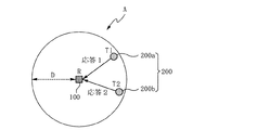
まず、図1は本発明の一実施例によるタグ対タグ衝突状況を示すものである。 First, FIG. 1 shows a tag-to-tag collision situation according to an embodiment of the present invention.
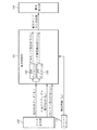
図1を参照すれば、‘タグ対タグ衝突’状況は一つのRFIDリーダであるR(100)の読み取り範囲(read range)であるA内に複数のタグ200が与えられた場合に発生することになる。図1の実施例においては、二つのタグであるT1(200a)とT2(200b)が与えられた場合を例としたが、これに限定されるものではなく、それ以上のタグが与えられた場合にも適用可能である。
Referring to FIG. 1, a “tag-to-tag collision” situation occurs when a plurality of
まず、R(100)がインベントリ命令(inventory command)を出力すれば、A内に位置するT1(200a)とT2(200b)がR(100)のインベントリ命令に対して応答することになる。この際、T1(200a)とT2(200b)が同時に応答する場合、T1(200a)とT2(200b)による並列的な応答は相手タグの応答を邪魔することになる。これがまさに‘タグ対タグ衝突’である。 First, if R (100) outputs an inventory command (inventory command), T1 (200a) and T2 (200b) located in A respond to the inventory command of R (100). At this time, when T1 (200a) and T2 (200b) respond simultaneously, the parallel response by T1 (200a) and T2 (200b) disturbs the response of the counterpart tag. This is exactly 'tag-to-tag collision'.
‘タグ対タグ衝突’が発生した場合、R(100)はタグ対タグ衝突によってT1(200a)及びT2(200b)から受信されたタグ応答をデコードするのにエラーが発生することになる。よって、インベントリ命令を出力したR(100)は各タグの応答を正確に区分することができなくなる。このような‘タグ対タグ衝突’は無線インターフェース仕様(例えば、ISO/IEC 18000−6 Type C)に紹介されているタグ衝突調整アルゴリズム(anti−collision algorithm)によって解決可能である。以下で、タグ衝突調整は他の説明がなければタグ対タグ衝突を解決する従来のアルゴリズムを意味する。 If a 'tag-to-tag collision' occurs, an error occurs when R (100) decodes the tag response received from T1 (200a) and T2 (200b) due to the tag-to-tag collision. Therefore, R (100) that has output the inventory command cannot accurately distinguish the response of each tag. Such 'tag-to-tag collision' can be solved by a tag collision adjustment algorithm introduced in a wireless interface specification (for example, ISO / IEC 18000-6 Type C). In the following, tag collision adjustment means a conventional algorithm for resolving tag-to-tag collision unless otherwise explained.
以下の説明で、‘タグ対タグ衝突’は便宜上第1衝突として説明する。 In the following description, 'tag-to-tag collision' will be described as the first collision for convenience.
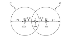
一方、図2は本発明の一実施例によるマルチリーダ対タグ衝突状況を示すものである。 Meanwhile, FIG. 2 shows a multi-reader-to-tag collision situation according to an embodiment of the present invention.
図2を参照すれば、‘マルチリーダ対タグ衝突’状況は複数のRFIDリーダによって発生される。図2の実施例では二つのRFIDリーダであるR1(100a)とR2(100b)が与えられた場合を例としたが、これに限定されるものではなく、それ以上のRFIDリーダが与えられた場合にも適用可能であるのはいうまでもない。 Referring to FIG. 2, the 'multi-reader vs. tag collision' situation is generated by a plurality of RFID readers. In the embodiment of FIG. 2, an example is given where two RFID readers R1 (100a) and R2 (100b) are provided, but the present invention is not limited to this, and more RFID readers are provided. Needless to say, this is also applicable to cases.
言い換えれば、R1(100a)の読み取り範囲であるA1と、R2(100b)の読み取り範囲である‘A2’が一部重なる状態で、A1とA2が一部重なる範囲内に一つのタグであるT(200)が位置する場合を例として説明する。 In other words, in the state where A1 which is the reading range of R1 (100a) and 'A2' which is the reading range of R2 (100b) partially overlap, T1 which is one tag within the range where A1 and A2 partially overlap A case where (200) is located will be described as an example.
この際、R1(100a)とR2(100b)がT(200)にインベントリ命令を出力する場合、R1(100a)及びR2(100b)から出力されたインベントリ命令はT(200)で衝突することができる。この場合、T(200)はR1(100a)及びR2(100b)からそれぞれ受信されたインベントリ命令をデコードする場合にエラーが発生することになる。 At this time, if R1 (100a) and R2 (100b) output an inventory command to T (200), the inventory commands output from R1 (100a) and R2 (100b) may collide at T (200). it can. In this case, an error will occur when T (200) decodes the inventory commands received from R1 (100a) and R2 (100b), respectively.
以下の説明で、‘マルチリーダ対タグ衝突’は便宜上第2衝突として説明する。 In the following description, 'multi-reader vs. tag collision' will be described as a second collision for convenience.
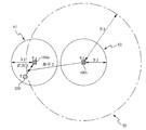
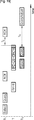
一方、図3は本発明の一実施例によるリーダ対リーダ衝突状況を示すものである。 On the other hand, FIG. 3 shows a reader-to-reader collision situation according to an embodiment of the present invention.
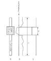
図3を参照すれば、‘リーダ対リーダ衝突’は二つのRFIDリーダであるR1(100a)とR2(100b)が存在し、R2(100b)の干渉範囲(interference range)であるB2がR1(100a)の読み取り範囲であるA1と重なる場合に発生することになる。図3の実施例では二つのRFIDリーダが与えられた場合を例としたが、これに限定されるものではなく、それ以上のRFIDリーダが与えられた場合にも適用可能であるのはいうまでもない。ここで、‘リーダ対リーダ衝突’はR1(100a)及びR2(100b)の読み取り範囲が重ならない状況でも発生することができるものである。 Referring to FIG. 3, the reader-reader collision has two RFID readers R1 (100a) and R2 (100b), and B2 which is an interference range of R2 (100b) is R1 (interference range). This occurs when it overlaps A1 which is the reading range of 100a). In the embodiment of FIG. 3, the case where two RFID readers are provided is taken as an example. However, the present invention is not limited to this, and can be applied to cases where more RFID readers are provided. Nor. Here, 'reader-reader collision' can occur even in a situation where the reading ranges of R1 (100a) and R2 (100b) do not overlap.
例えば、R1(100a)がA1内に位置するタグであるT(200)にインベントリ命令を出力すれば、T(200)はR1(100a)のインベントリ命令に対する応答信号をR1(100a)に伝送する。よって、R1(100a)はT(200)から受信された応答信号に応じた動作を遂行することになる。この際、A1とB2が重なることになるので、R2(100b)から出力された所定の命令またはその他の信号とR1(100a)に入力されるT(200)の応答信号が衝突することになる。これがまさに‘リーダ対リーダ衝突’である。 For example, if R1 (100a) outputs an inventory command to T (200) that is a tag located in A1, T (200) transmits a response signal to the inventory command of R1 (100a) to R1 (100a). . Therefore, R1 (100a) performs an operation according to the response signal received from T (200). At this time, since A1 and B2 overlap, a predetermined command or other signal output from R2 (100b) and a response signal of T (200) input to R1 (100a) collide. . This is exactly the “reader-to-reader collision”.
従来、RFIDリーダ間の衝突状況でR1(100a)はT(200)から受信された応答信号からエラーが検出された場合、これをタグ対タグ衝突と見誤ってそれに応じた衝突調整アルゴリズムを適用することで衝突を解決しようとした。 Conventionally, when an error is detected from the response signal received from T (200) in R1 (100a) in a collision situation between RFID readers, this is mistaken as a tag-to-tag collision, and a corresponding collision adjustment algorithm is applied. Tried to resolve the conflict.
また、‘リーダ対リーダ衝突’は二つのRFIDリーダの読み取り範囲が重ならない状況でも発生することができるため、無線インターフェース仕様でも解決策が提示されていない。よって、モバイルRFID応用において‘リーダ対リーダ衝突’を検出するためのメカニズムが必要であった。よって、後述した本発明の実施例ではリーダ対リーダ衝突を検出するための実施例を説明した。 Also, 'reader-reader collision' can occur even when the reading ranges of the two RFID readers do not overlap, so no solution is presented even in the wireless interface specification. Therefore, a mechanism for detecting 'reader-reader collision' in mobile RFID applications is required. Therefore, in the embodiments of the present invention described later, an embodiment for detecting a reader-to-reader collision has been described.
以下の説明で、‘リーダ対リーダ衝突’は便宜上第3衝突として説明する。 In the following description, 'leader-to-reader collision' will be described as a third collision for convenience.
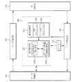
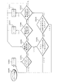
図4は本発明の一実施例によるRFIDリーダの構成を説明するのに参照する図である。 FIG. 4 is a diagram for explaining the configuration of an RFID reader according to an embodiment of the present invention.
図4を参照すれば、本発明によるRFIDリーダは、リーダ制御部110、リーダ送信部120、RF通信部130、リーダ受信部140、衝突制御部160及びタイマー150を含む。
Referring to FIG. 4, the RFID reader according to the present invention includes a
リーダ制御部110は所定範囲内に位置する少なくとも一つのタグにインベントリ命令を出力し、インベントリ命令に応じて受信されたタグ応答を処理する。
The
リーダ送信部120(モデム送信部)はリーダ制御部110のインベントリ命令をRF通信部130に伝達する。ここで、リーダ送信部120はリーダ制御部110から出力されたインベントリ命令を変調してRF通信部130に伝達する。
The reader transmission unit 120 (modem transmission unit) transmits the inventory command of the
RF通信部130はリーダ制御部110のインベントリ命令をリーダ送信部120から受け、所定範囲内に位置する少なくとも一つのタグに送出する。また、RF通信部130は、インベントリ命令を外部に送出した後、所定の受信時間の間に外部からの信号を受信する。この際、RF通信部130は所定の受信時間の間にすでに送出されたインベントリ命令に応じて読み取り範囲内のタグからタグ応答を受信する。もちろん、RF通信部130はタグ応答の外に他のRFIDリーダの信号または何の信号も含まないノイズなどを受信することもできる。この際、RF通信部130は受信信号をリーダ受信部140に伝達する。
The
リーダ受信部140(モデム受信部)はRF通信部130からの受信信号をリーダ制御部110及び衝突制御部160に伝達する。この際、リーダ受信部140は受信信号データを衝突制御部160に伝達するようにする。
The reader receiving unit 140 (modem receiving unit) transmits a reception signal from the
一方、リーダ受信部140はデコーダ(図示せず)を含む。この際、デコーダはRF通信部130からの受信信号を復号化し、復号化された受信信号から有効プリアンブルを検出するようにする。リーダ受信部140はデコーダの有効プリアンブル検出結果によって衝突制御部160に有効プリアンブル検出信号(VPD、Valid Preamble Detection)を出力するようにする。
Meanwhile, the
また、デコーダは復号化された受信信号からCRC(Cyclic Redundancy Check)エラーを検出するようにする。リーダ受信部140はデコーダのCRCエラー検出結果によって衝突制御部160にCRCエラー検出信号を出力するようにする。
The decoder detects a CRC (Cyclic Redundancy Check) error from the decoded received signal. The
衝突制御部160は衝突診断部161及び衝突解決部165を含む。
The
衝突診断部161は、リーダ受信部140から入力された受信信号データを分析して受信信号に対する衝突発生の有無を確認し、受信信号データの分析結果によって衝突タイプを診断するようにする。
The
ここで、衝突診断部161は有効ビット検出モジュールであるVBD(Valid Bit Detection)モジュール163を含む。VBDモジュール163は衝突診断部161のサブモジュールで、リーダ受信部140から入力された受信信号から有効ビットを検出する。言い換えれば、VBDモジュール163は、無線インターフェース仕様の許容誤差内で受信信号の立上りエッジ(rising edge)及び立下りエッジ(falling edge)、つまり変調された副搬送波を検出することで有効な論理的な信号を検出する。この際、VBDモジュール163は有効ビット検出結果によって有効ビット検出信号を出力する。
Here, the
衝突診断部161は、有効ビット検出信号が感知(detect)された場合、有効ビット検出信号(VBD)がポジティブ(positive)なものと判断する。言い換えれば、衝突診断部161は、有効ビット検出信号が感知された場合、VBDモジュール163から有効ビットが検出されたと判断する。
The
一方、衝突診断部161は、有効ビット検出信号が感知されない場合、有効ビット検出信号(VBD)がネガティブ(negative)なものと判断する。言い換えれば、衝突診断部161は、有効ビット検出信号が感知された場合、VBDモジュール163から有効ビットが検出されなかったと判断する。
On the other hand, when the valid bit detection signal is not detected, the
衝突診断部161は、VBDモジュール163から出力された有効ビット検出信号に基づき、送信信号に応じたタグ応答信号が存在するかどうかを判断する。これにより、衝突診断部161は、受信信号が送信信号に応じたタグ応答であるか、それとも何の信号も含んでいない信号であるかなどを判断する。
The
一方、衝突診断部161はRFIDリーダの衝突を感知するリーダ衝突感知モジュールであるICD(Interrogator Collision Detection)モジュール162をさらに含む。ICDモジュール162はVBDモジュール163と同様に衝突診断部161のサブモジュールで、リーダ受信部140から入力された受信信号データを分析し、受信信号データに対する平均値を算出する。
On the other hand, the
また、ICDモジュール162は受信信号データから算出された平均値と登録された基準レベルの比較結果によってRFIDリーダの衝突を感知する。この際、ICDモジュール162はRFIDリーダの衝突が感知された場合、リーダ衝突検出信号(ICD)を出力する。
Further, the
例えば、ICDモジュール162は、受信信号データから算出された平均値が基準レベル以上の場合、RFIDリーダが衝突したと感知する。一方、ICDモジュール162は、受信信号データから算出された平均値が基準レベル未満の場合、RFIDリーダが衝突しなかったと感知する。
For example, when the average value calculated from the received signal data is equal to or higher than the reference level, the
これに対する具体的な実施例は図6及び図7を参照するようにする。 A specific embodiment for this will be described with reference to FIGS.
衝突診断部161は、ICDモジュール162から出力されたリーダ衝突検出信号に基づいて当該RFIDリーダと周辺RFIDリーダの衝突、つまり第3衝突の発生有無を確認することが可能である。
The
言い換えれば、衝突診断部161は、リーダ衝突検出信号が感知された場合、リーダ衝突検出信号(ICD)がポジティブ(positive)なものと判断する。言い換えれば、衝突診断部161は、リーダ衝突検出信号が感知された場合、ICDモジュール162からRFIDリーダの衝突が検出されたと判断する。この際、衝突診断部161は受信信号に対して第3衝突が発生したと診断する。
In other words, the
一方、衝突診断部161は、リーダ衝突検出信号が感知されない場合、リーダ衝突検出信号(ICD)がネガティブ(negative)なものと判断する。言い換えれば、衝突診断部161は、有効ビット検出信号が感知された場合、VBDモジュール163から有効ビットが検出されなかったと判断する。この際、衝突診断部161は受信信号に対して第3衝突は発生しなかったと診断する。
On the other hand, when the leader collision detection signal is not detected, the
また、衝突診断部161は、ICDモジュール162から出力されたリーダ衝突検出信号がネガティブ(negative)なものと判断されれば、VBDモジュール163から出力された有効ビット検出信号に基づいて複数の周辺タグ間の衝突、つまり第1衝突の発生有無を確認する。また、衝突診断部161はVBDモジュール163から出力された有効ビット検出信号に基づいて複数のRFIDリーダと送信信号を受信したタグ間の衝突、つまり第2衝突の発生有無を確認する。
In addition, if the
衝突診断部161は、VBDモジュール163から有効ビット検出信号(VBD)がポジティブなものと判断されれば、受信信号に対して第1衝突が発生したと診断する。一方、衝突診断部161は、VBDモジュール163から有効ビット検出信号(VBD)がネガティブなものと判断されれば、受信信号に対して第2衝突が発生したと診断する。
If the
衝突診断部161は、デコーダから有効プリアンブルが検出された場合、リーダ受信部140から有効プリアンブル検出信号を受信する。また、衝突診断部161は、デコーダからCRCエラーが検出された場合、リーダ受信部140からCRCエラー検出信号を受信する。ここで、衝突診断部161は、リーダ受信部140から出力された有効プリアンブル検出信号とCRCエラー検出信号に基づいて受信信号に対する衝突タイプを診断するようにする。
The
すなわち、衝突診断部161は、ICDモジュール162から出力されたリーダ衝突検出信号とVBDモジュール163から出力された有効ビット検出信号に基づいて、第1衝突、第2衝突、及び第3衝突に対する衝突タイプを診断することができる。これに対する実施例は[表1]を参照する。
また、衝突診断部161は、ICDモジュール162から出力されたリーダ衝突検出信号及びVBDモジュール163から出力された有効ビット検出信号に加え、リーダ受信部140から入力された有効プリアンブル検出信号とCRCエラー検出信号をさらに参照してより細密な衝突タイプを診断することができることになる。これに対する実施例はつぎの[表2]を参照する。
衝突診断部161は、前記のような条件を満足する場合、衝突状況と判断し、第1衝突、第2衝突、及び第3衝突の中でいずれか一つの衝突タイプと診断し、前記のような条件を満足しない場合、受信信号に衝突が発生しないと判断する。
When the above conditions are satisfied, the
この際、衝突診断部161は、衝突診断結果を衝突解決部165に伝達するようにする。ここで、衝突診断結果は衝突発生の有無を含み、衝突が発生した場合、衝突タイプ情報を含む。
At this time, the
衝突解決部165は、衝突診断部161から印加された衝突診断結果に応じた動作を遂行するようにする。言い換えれば、衝突解決部165は、衝突診断部161によって衝突が発生しなかったと診断されれば、これをリーダ制御部110に通報するようにする。
The
また、衝突解決部165は、タグ対タグ衝突、マルチリーダ対タグ衝突及びリーダ対リーダ衝突の中でいずれか一つの衝突が発生した場合、各衝突タイプに応じた衝突解決アルゴリズム(collision resolution algorithm)を遂行することで衝突問題を解決するようにする。衝突解決部165は、衝突発生の有無と衝突タイプに基づいて命令を再伝送するか否かを判断する状況別命令再伝送部1651、及び命令の再伝送のためのランダム待機時間を計算するランダム待機時間計算部1652を備え、衝突解決部165の具体的な動作については衝突診断部161が衝突を診断する動作を説明した後に説明する。
Also, the
図5は本発明による衝突制御部の動作説明するのに参照する図である。 FIG. 5 is a diagram for explaining the operation of the collision control unit according to the present invention.
図5を参照すれば、衝突診断部161は、リーダ受信部140から受信信号データ(I1)を受ける。この際、衝突診断部161のVBDモジュール163は、受信信号データから有効ビットを検出して有効ビット検出信号(I11)を出力する。また、衝突診断部161のICDモジュール162は受信信号データからリーダ衝突を検出してリーダ衝突検出信号(I12)を出力する。
Referring to FIG. 5, the
一方、衝突診断部161は、リーダ受信部140から有効プリアンブル検出信号(I2)とCRCエラー検出信号(I3)を受ける。
On the other hand, the
また、衝突診断部161はタイマー150から時間情報(I4)を受ける。この際、衝突診断部161は、タイマー150から提供された時間情報(I4)に基づき、送信信号に対して設定された受信時間がタイムアウトされるまでの時間をカウントする。また、衝突診断部161は、送信信号に応じたタグ応答が受信されるまでの時間をカウントする。
The
衝突診断部161は、有効ビット検出信号(I11)、リーダ衝突検出信号(I12)、有効プリアンブル検出信号(I2)、及びCRCエラー検出信号(I3)情報を利用して受信信号に対する衝突発生の有無及び発生した衝突タイプを診断するようにする。
The
この際、衝突診断部161は衝突診断結果を衝突解決部165に出力することになる。ここで、衝突診断結果は衝突なし(No collision detected)、第1衝突、第2衝突、及び第3衝突に対する情報を含む。もちろん、衝突診断結果は診断された衝突を解決するための衝突制御命令を含むことができる。
At this time, the
図6及び図7は衝突診断部のICDモジュールでICDを検出する動作説明に参照する図である。 6 and 7 are diagrams to be referred to for explaining the operation of detecting the ICD by the ICD module of the collision diagnosis unit.
ICDモジュール162でICD信号を検出するに先立ち、衝突診断部161はICDモジュール162のパラメーター値を調整する。
Prior to detecting the ICD signal by the
例えば、衝突診断部161は、リンク周波数(LF、Link Frequency)、データ速度(data rate)、信号変調タイプなどから移動平均フィルター(MAF、Moving Average Filter)のウィンドウ(またはタブ)の大きさを決定する。ここで、受信信号データに対する平均値を算出する区間であるウィンドウの大きさは手動または自動で調整することができる。
For example, the
衝突診断部161は、送信信号に対するタグ応答を受信するためのタグ応答周期を決定する。ここで、タグ応答周期は、リンク周波数、データ速度及び変調タイプなどから決定される。
The
また、衝突診断部161は、ICDモジュール162でリーダ信号を検出するために基準となる基準レベル(Threshold_level)を決定する。ここで、基準レベルは、信号変調タイプ、リンク周波数(LF)、データ速度の中で少なくとも一つ以上によって決定される。
Further, the
前記のように、衝突診断部161によってICDモジュール162のパラメーター値が決定された後、ICDモジュール162はリーダ受信部140から入力される受信信号のシンボルデータによってRFIDリーダの衝突有無を検査するようにする。
As described above, after the parameter value of the
図6は本発明によるICDモジュールの構成を示す例示図、図7はICDモジュールでの信号流れを示す図である。図6及び図7を参照すれば、ICDモジュール162は平均計算部162aと比較器162bを含む。
FIG. 6 is an exemplary diagram showing a configuration of an ICD module according to the present invention, and FIG. 7 is a diagram showing a signal flow in the ICD module. Referring to FIGS. 6 and 7, the
平均計算部162aは、リーダ受信部140から入力された受信信号データを入力値として受けて入力された受信信号データに対する平均値を算出する。この際、平均計算部162aは移動平均フィルター(Moving Average Filter、MAF)を含む。すなわち、平均計算部162aは、移動平均フィルター(MAF)に受信信号データが入力されれば、移動平均フィルターのウィンドウに入力された各フィルター値(S1、S2、S3、...、Sn)を合わせて平均値を算出するようにする。すなわち、移動平均フィルターのウィンドウに入力された区間の平均値を算出するようにする。受信信号のデータが移動平均フィルターのウィンドウに追加入力される場合、追加入力された受信信号データに対する平均値を算出するようにする。
The
比較器162bは、平均計算部162aから算出された平均値と登録された基準レベル(threshold_level)を比較し、リーダ衝突検出信号を出力するようにする。この際、比較器162bは、平均計算部162aから算出された平均値の中で基準レベル以上の値に対してリーダ衝突検出信号を出力するようにする。この際、衝突診断部160は当該リーダ衝突検出信号、つまりICDがポジティブ(positive)状態のものとみなす。
The
すなわち、衝突診断部161は、リーダ衝突検出信号においてICDが‘positive’状態の場合、当該RFIDリーダと周辺RFIDリーダの間で第3衝突が発生したとみなす。この際、ICD値は衝突関係にあるリーダを知らせるものである。
That is, when the ICD is in the “positive” state in the reader collision detection signal, the
言い換えれば、図7の(a)のように受信信号のシンボルデータが入力された場合、衝突診断部160によって決定されたタグ応答時間(T1)の間に入力された受信信号データに対する移動平均フィルター区間の平均値は図7の(b)のようである。ここで、衝突診断部160は送信信号を送出した後に所定の受信時間の間にRF通信部130から受信信号を受信する。本実施例ではタグ応答時間(T1)の間に受信信号を受信することにする。
In other words, when symbol data of the received signal is input as shown in FIG. 7A, the moving average filter for the received signal data input during the tag response time (T1) determined by the
この際、ICDモジュール162は(b)の平均値のうち、先に衝突診断部161によって決定された基準レベル(Threshold_level)と比較するようにする。その結果、ICDモジュール162は図7の(c)のようにリーダ衝突検出信号を衝突診断部161に出力するようにする。すなわち、タグ応答時間である‘T1’の間の平均値の中で基準レベルを超える領域である‘T2’でICDが‘positive’状態となることを確認することができる。
At this time, the
したがって、衝突診断部161は、ICDモジュール162から出力されたリーダ衝突検出信号に基づいて受信信号で第3衝突が発生したと判断する。
Therefore, the
図8はVBDモジュールで有効ビットを検出する実施例を示すものである。特に、Miller−4でエンコードされた受信信号から有効ビットを検出する例を示すものである。 FIG. 8 shows an embodiment in which a valid bit is detected by the VBD module. In particular, an example in which valid bits are detected from a reception signal encoded by Miller-4 is shown.
ここで、VBDモジュール163によって有効ビットが検出された場合、VBDは‘positive’となり、有効ビットが検出されない場合には、VBDが‘negative’となる。VBDモジュール163は有効ビット検出結果によって有効ビット検出信号を出力する。これにより、衝突診断部161はVBDモジュール163から出力された有効ビット検出信号に基づいて受信信号の衝突タイプを診断するようにする。
Here, when a valid bit is detected by the
したがって、衝突診断部161は先に獲得された情報、つまりリーダ衝突検出信号、有効ビット検出信号、有効プリアンブル検出信号、及びCRCエラー検出信号から図9〜図11の衝突タイプを診断することができることになる。
Therefore, the
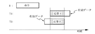
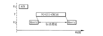
まず、図9は第1衝突状況を示すもので、詳しくはRFIDリーダ(R)とタグ1(T1)及びタグ2(T2)の間で送受信される命令及び応答信号を示すものである。ただし、他のRFIDリーダからの干渉はない状態とみなす。 First, FIG. 9 shows a first collision situation. Specifically, FIG. 9 shows commands and response signals transmitted and received between the RFID reader (R) and the tag 1 (T1) and the tag 2 (T2). However, it is assumed that there is no interference from other RFID readers.
まず、RFIDリーダ(R)がタグ1(T1)及びタグ2(T2)に命令を伝送すれば、タグ1(T1)及びタグ2(T2)はそれぞれ応答1と応答2をRFIDリーダ(R)に伝送する。この際、同一応答スロット(response slot)で二つ以上のタグ応答、つまり応答1と応答2の一部がオーバーラップされることにより衝突が発生することになる。
First, if the RFID reader (R) transmits a command to the tag 1 (T1) and the tag 2 (T2), the tag 1 (T1) and the tag 2 (T2) respectively send a
この際、衝突診断部161は、つぎの<条件A>または<条件B>を満足する場合、第1衝突が発生したと診断する。
<条件A> 1)有効プリアンブル検出(VPD is positive)。
2)CRCエラー検出。
3)有効ビット検出(VBD is positive)。
4)検出されたリーダ衝突なし(ICD is negative)。
<条件B> 1)検出された有効プリアンブルなし(VPD is negative)。
2)有効ビット検出(VBD is positive)。
3)検出されたリーダ衝突なし(ICD is negative)。
言い換えれば、<条件A>のように、有効プリアンブル検出信号からVPDが‘positive’であり、CRCエラーが検出され、有効ビット検出信号からVBDが‘positive’で、リーダ衝突検出信号からICDが‘negative’であることを満足する場合、衝突診断部161は受信信号で第1衝突が発生したと診断する。一方、<条件B>のように、VPDが‘negative’で、VBDが‘positive’で、ICDが‘negative’であることを満足する場合、衝突診断部161は受信信号で第1衝突が発生したと診断する。
At this time, the
<Condition A> 1) Effective preamble detection (VPD is positive).
2) CRC error detection.
3) Valid bit detection (VBD is positive).
4) No detected reader collision (ICD is negative).
<Condition B> 1) No valid preamble detected (VPD is negative).
2) Valid bit detection (VBD is positive).
3) No detected reader collision (ICD is negative).
In other words, as in <Condition A>, VPD is' positive 'from the effective preamble detection signal, a CRC error is detected, VBD is'positive' from the effective bit detection signal, and ICD is' from the reader collision detection signal. When satisfying that it is negative ′, the
したがって、衝突診断部161は<条件A>及び<条件B>のいずれか一つを満足する場合、第1衝突情報を含む衝突診断結果を衝突解決部165に出力するようにする。
Therefore, the
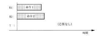
図10は第2衝突状況を示すもので、詳しくはリーダ1及びリーダ2と一つのタグの間で送受信される命令及び応答信号を示すものである。
FIG. 10 shows the second collision situation, and more specifically shows commands and response signals transmitted / received between the
図10に示すように、RFIDリーダ1(R1)とRFIDリーダ2(R2)はタグ(T)に命令を出力する。この際、RFIDリーダ1(R1)とRFIDリーダ2(R2)からそれぞれ出力された命令1と命令2がオーバーラップされた場合、衝突が発生することになる。この場合、タグは有効なRFIDリーダの命令を検出することができないので、タグ応答は出力されなくなる。よって、RF通信部130は、送信信号を送出した後に他のRFIDリーダの信号またはノイズなどを受信することになる。
As shown in FIG. 10, the RFID reader 1 (R1) and the RFID reader 2 (R2) output a command to the tag (T). At this time, when the
この際、衝突診断部161はつぎの<条件C>を満足する場合、第2衝突が発生したと診断する。
<条件C> 1)検出された有効プリアンブルなし(VPD is negative)。
2)検出された有効ビットなし(VBD is negative)。
3)検出されたリーダ衝突なし(ICD is negative)。
At this time, the
<Condition C> 1) No valid preamble detected (VPD is negative).
2) No detected valid bit (VBD is negative).
3) No detected reader collision (ICD is negative).
<条件C>のように、VPDが‘negative’で、VBDが‘negative’で、ICDが‘negative’であることを満足する場合、衝突診断部161は受信信号で第2衝突が発生したと診断する。
As in <Condition C>, when the VPD is 'negative', the VBD is 'negative', and the ICD is 'negative', the
したがって、衝突診断部161は、<条件C>を満足する場合、第2衝突情報を含む衝突診断結果を衝突解決部165に出力するようにする。
Therefore, the
図11は第3衝突状況を示すもので、詳しくはリーダ1及びリーダ2と一つのタグの間で送受信される命令及び応答信号を示すものである。
FIG. 11 shows a third collision situation, and more specifically shows commands and response signals transmitted and received between the
まず、RFIDリーダ1(R1)がタグ(T)に命令1を伝送すれば、タグ(T)はRFIDリーダ1(R1)の命令1に応じて応答1をRFIDリーダ1(R1)に伝送する。一方、RFIDリーダ2(R2)は他のタグに命令2を伝送する。
First, if the RFID reader 1 (R1) transmits a
この際、RFIDリーダ1(R1)の読み取り範囲とRFIDリーダ2(R2)の干渉範囲が重なるので、タグ(T)の応答1とRFIDリーダ2(R2)の命令2が互いにオーバーラップされることによって衝突が発生することになる。図11の(a)は応答1の一部が命令2とオーバーラップされた場合を示すものであり、図11の(b)は応答1の全体が命令2とオーバーラップされた場合を示すものである。ここで、図11の(a)及び(b)は伝送されるプロトコルデータユニット(protocol data unit)のアクチュアルタイミング(actual timing)によって発生することになる。
At this time, since the reading range of the RFID reader 1 (R1) and the interference range of the RFID reader 2 (R2) overlap, the
この際、衝突診断部161は、つぎの<条件D>または<条件E>を満足する場合、第3衝突が発生したと診断する。
<条件D> 1)有効プリアンブル検出(VPD is positive)。
2)CRCエラー検出。
3)リーダ衝突検出(ICD is positive)。
<条件E> 1)検出された有効プリアンブルなし(VPD is negative)。
2)リーダ衝突検出(ICD is positive)。
At this time, the
<Condition D> 1) Effective preamble detection (VPD is positive).
2) CRC error detection.
3) Reader collision detection (ICD is positive).
<Condition E> 1) No valid preamble detected (VPD is negative).
2) Reader collision detection (ICD is positive).
まず、<条件D>のように、VPDが‘positive’で、CRCエラーが検出され、ICDが‘positive’である場合、衝突診断部161は受信信号で第3衝突が発生したと診断する。一方、<条件E>のように、VPDが‘negative’で、ICDが‘positive’である場合、衝突診断部161は受信信号で第3衝突が発生したと診断する。
First, as in <Condition D>, when the VPD is 'positive', a CRC error is detected, and the ICD is 'positive', the
ここで、ICDは基本的に当該RFIDリーダと周辺RFIDリーダ間の衝突を検出する信号なので、ただ第3衝突でだけ‘positive’状態となる。よって、衝突診断部161は、<条件D>または<条件E>を満足する場合、第3衝突情報を含む衝突診断結果を衝突解決部165に出力するようにする。
Here, since the ICD is basically a signal for detecting a collision between the RFID reader and the peripheral RFID reader, it is in a 'positive' state only by the third collision. Therefore, the
その後、衝突解決部165は衝突診断部161によって診断された衝突を解決し、発生する衝突を最小化するため、発生した衝突タイプに応じた衝突解決アルゴリズムを遂行するようにする。衝突解決部165は、衝突解決アルゴリズムを遂行した後、遂行結果をリーダ制御部110に伝達する。
Thereafter, the
前記のように構成された本発明の動作を説明すれば次のようである。 The operation of the present invention configured as described above will be described as follows.
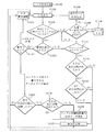
図12〜図14は本発明の一実施例によるRFIDリーダの動作フローを示すフローチャートである。 12 to 14 are flowcharts showing an operation flow of the RFID reader according to the embodiment of the present invention.
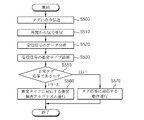
まず、図12はRFIDリーダの全体動作フローを示すものである。図12を参照すれば、RFIDリーダは、周辺のタグに送信信号、つまりインベントリ命令を伝送する(S500)。当該RFIDリーダのRF通信部130は、‘S500’過程で伝送された送信信号に応じて、所定の受信時間の間に外部から信号を受信する(S510)。この際、RF通信部130は、当該RFIDリーダの読み取り範囲内にある少なくとも一つのタグからタグ応答信号を受信することになる。もちろん、‘S510’過程で受信される信号はタグ応答信号の外に他のRFIDリーダの信号またはノイズを含むこともできる。
First, FIG. 12 shows an overall operation flow of the RFID reader. Referring to FIG. 12, the RFID reader transmits a transmission signal, that is, an inventory command, to peripheral tags (S500). The
RFIDリーダの衝突診断部161は、‘S510’過程で受信された受信信号のデータを分析し(S520)、受信信号の衝突発生の有無及び衝突タイプを診断するようにする(S530)。
The
‘S530’過程での診断結果、当該受信信号が正常タグ応答信号であると判断されれば(S550)、衝突診断部161はこれを知らせる信号を衝突解決部165に出力するようにする。この際、衝突解決部165は、衝突診断部161の衝突診断結果をリーダ制御部110に伝達することにより、リーダ制御部110がタグ応答によって応じた動作を遂行するようにする(S570)。
If it is determined that the received signal is a normal tag response signal as a result of the diagnosis in the process of ‘S530’ (S550), the
‘S530’過程での診断結果、当該受信信号で衝突が発生したと判断されれば(S550)、衝突診断部161は、衝突解決部165に衝突診断結果を出力するようにする。この際、衝突解決部165は、衝突診断部161の衝突診断結果に基づき、当該衝突タイプに応じた衝突解決アルゴリズムを遂行するようにする(S560)。
If it is determined that a collision has occurred in the received signal as a result of the diagnosis in the 'S530' process (S550), the
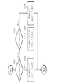
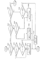
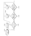
図13及び図14は図12の‘S530’過程の詳細過程を示すもので、図13は簡単な動作フローを示すものであり、図14は図13をより細分化した動作フローを示すものである。 13 and 14 show the detailed process of the 'S530' process of FIG. 12, FIG. 13 shows a simple operation flow, and FIG. 14 shows an operation flow that is a more detailed version of FIG. is there.
まず、図13を参照すれば、衝突診断部161は、リーダ受信部140から入力された受信信号のデータを分析結果、ICDモジュール162から出力されたリーダ衝突検出信号及びVBDモジュール163から出力された有効ビット検出信号に基づき、受信信号で発生した衝突タイプを診断する。
First, referring to FIG. 13, the
ICDモジュール162から出力されたリーダ衝突検出信号に基づいて‘ICD=positive’の場合(S531)、衝突診断部161は、受信信号の衝突タイプを‘第3衝突タイプ’、つまりリーダ対リーダ衝突タイプと診断するようにする。
If 'ICD = positive' based on the reader collision detection signal output from the ICD module 162 (S531), the
ICDモジュール162から出力されたリーダ衝突検出信号から‘ICD=positive’でない場合(S531)、‘S532’過程に進み‘VBD=positive’であるかを確認する。VBDモジュール163から出力された有効ビット検出信号から‘VBD=positive’であるものが確認されれば(S532)、衝突診断部161は、受信信号の衝突タイプを‘第2衝突タイプ’、つまりマルチリーダ対タグ衝突タイプと診断するようにする。一方、‘VBD=positive’でなければ(S532)、衝突診断部161は、受信信号の衝突タイプを‘第1衝突タイプ’、つまりタグ対タグ衝突タイプと診断するようにする。
If it is not ‘ICD = positive’ from the reader collision detection signal output from the ICD module 162 (S531), the process proceeds to ‘S532’ and confirms whether ‘VBD = positive’. If it is confirmed from the valid bit detection signal output from the
図14を参照すれば、衝突診断部161は、ICDモジュール162から出力されたリーダ衝突検出信号に基づいて‘ICD=positive’の場合(S531)、‘S533’過程に進み‘VPD=positive’であるかを確認する。‘VPD=positive’でないものが確認されれば、衝突診断部161は、受信信号の衝突タイプを‘第3衝突タイプ’、つまりリーダ対リーダ衝突タイプとで診断するようにする(S535)。
Referring to FIG. 14, the
‘S533’過程で‘VPD=positive’の場合、衝突診断部161は、‘S534’過程に進みCRCエラーが発生したかを確認する。CRCエラーが発生したことが確認された場合、衝突診断部161は、受信信号の衝突タイプを‘第3衝突タイプ’、つまりリーダ対リーダ衝突タイプと診断するようにする(S535)。この際、‘S534’過程でCRCエラーが発生しないことが確認されれば、衝突診断部161は受信信号が正常タグ応答であると診断する(S536)。
If ‘VPD = positive’ in the ‘S533’ process, the
‘S531’過程で‘ICD=positive’でないことが確認されれば、衝突診断部161は‘S537’過程に進み‘VPD=positive’であるかを確認する。‘VPD=positive’でない場合、衝突診断部161は‘S538’過程に進み‘VBD=positive’であるかを確認する。‘VBD=positive’の場合、衝突診断部161は、受信信号の衝突タイプを‘第1衝突タイプ’、つまりタグ対タグ衝突タイプと診断するようにする(S540)。一方、‘VBD=positive’でない場合、衝突診断部161は、受信信号の衝突タイプを‘第2衝突タイプ’、つまりマルチリーダ対タグ衝突タイプと診断するようにする(S539)。
If it is confirmed in step ‘S531’ that ‘ICD = positive’ is not satisfied, the
一方、‘S537’過程で‘VPD=positive’であることが確認された場合、衝突診断部161は、‘S541’過程に進み‘VBD=positive’であるかを確認する。‘VBD=positive’の場合、衝突制御部161は‘S542’過程に進みCRCエラー発生有無を確認する。CRCエラーが発生したことが確認された場合、衝突診断部161は、受信信号の衝突タイプを‘第1衝突タイプ’、つまりタグ対タグ衝突タイプと診断するようにする(S540)。この際、‘S542’過程でCRCエラーが発生しないことが確認されれば、衝突診断部161は受信信号が正常タグ応答であると診断する(S536)。
On the other hand, when it is confirmed in the step ‘S537’ that ‘VPD = positive’, the
一方、‘S541’過程で‘VBD=positive’でない場合、図12の‘S500’過程に進み前記‘S500’〜‘S570’過程を再遂行するようにする。 On the other hand, if ‘VBD = positive’ is not satisfied in the ‘S541’ process, the process proceeds to the ‘S500’ process of FIG. 12 and the steps ‘S500’ to ‘S570’ are performed again.
次に、前述したことにより図4の衝突診断部161が衝突の発生有無を判断し、衝突が発生した場合、その衝突が本発明による3種衝突タイプの中でいずれに当たるかどうかを判断した後、その判断結果を受信した衝突解決部165が衝突を解決する方法について説明する。
Next, after the
まず、本発明によるメディアアクセス方法を簡単に説明すれば次のようである。RFIDリーダは、選択した周波数帯域の現在占有に関係なく準備(ready)されればインベントリラウンドを開始することができる。すなわち、モバイルRFIDに分離されたチャネルが割り当てられない限りLBTは必要でない。また、同一チャネル内で伝送するリーダの間に同期化する必要がない。すなわち、特別な制御チャネルを確保しなくても本発明を適用することができる。適応型再伝送待機時間と結合して衝突状況による命令再伝送を行うことが本発明の重要事項である。 First, the media access method according to the present invention will be briefly described as follows. The RFID reader can start an inventory round if it is ready regardless of the current occupation of the selected frequency band. That is, LBT is not required unless a separate channel is assigned to mobile RFID. Also, there is no need to synchronize between readers transmitting in the same channel. That is, the present invention can be applied without securing a special control channel. It is an important matter of the present invention to perform command retransmission according to the collision situation in combination with the adaptive retransmission waiting time.
図15は本発明の実施例によって衝突解決部165が衝突状況別に命令を再伝送する手順を示すフローチャートである。図15に示す手順は主に図4の状況別命令再伝送部1651によって遂行される。そして、衝突状況別に命令を再伝送するときに適用されるランダム待機時間を図4のランダム待機時間計算部1652が計算して状況別命令再伝送部1651に送信する。
FIG. 15 is a flowchart illustrating a procedure in which the
衝突状況による命令再伝送の基本内容を説明すれば次のようである。まず、マルチリーダ対タグ衝突またはリーダ対リーダ衝突が感知されれば命令が再伝送される。そして、リーダは、衝突が感知された後に命令を再伝送するに先立ち、ランダム時間の間に遅延(suspend)しなければならない。RFIDリーダで命令を伝送する間には衝突が感知されないので、命令の伝送が完了した後に衝突仲裁を開始することができる。すなわち、進行中の命令の伝送は中間にインターラプトされないと仮定する。 The basic contents of command retransmission according to the collision situation will be described as follows. First, if a multi-reader-to-tag collision or a reader-to-reader collision is detected, the command is retransmitted. The reader must then suspend for a random time before retransmitting the command after a collision is detected. Since no collision is detected during the transmission of the command by the RFID reader, the collision arbitration can be started after the transmission of the command is completed. That is, assume that the transmission of an ongoing command is not interrupted in the middle.
また、リーダ側で、例えばT2タイムアウトのようなレシーバータイムアウト(Receiver Timeout)が感知されれば、命令が再伝送される。レシーバータイムアウトは、例えば有効なRF変調、エンコード、またはメッセージ構造がないか、通信チャネル上に活動がなくてタグ状態マシンによってトリガーされるレシーバーアクティブ時間が終了することを意味する。レシーバータイムアウトがあればリーダは命令を再伝送する。 Further, if the reader side, for example, T 2 Receiver Timeout (Receiver Timeout) such as time-out is sensed, the instruction is re-transmitted. Receiver timeout means, for example, that there is no valid RF modulation, encoding, or message structure, or that there is no activity on the communication channel and the receiver active time triggered by the tag state machine expires. If there is a receiver timeout, the reader retransmits the command.
本発明による衝突仲裁(collision arbitration)は命令を少なくとも一度再伝送することで具現化される。そして、損傷されたタグ応答が繰り返し受信されたら、複数回にかけて命令を再伝送することができる。後続の衝突可能性を減少させるために、衝突が感知された後、ランダム待機時間の間にリーダを遅延させることで衝突回避が具現化できる。 Collision arbitration according to the present invention is implemented by retransmitting the command at least once. And if the damaged tag response is received repeatedly, the command can be retransmitted multiple times. In order to reduce the possibility of subsequent collisions, collision avoidance can be implemented by delaying the reader during a random waiting time after a collision is detected.
また、タグが現在の応答スロット(response slot)ですでに分離(separate)された後、つまりタグACK(acknowledgement)とタグアクセス期間の間に、リーダによって通信衝突が感知されれば、マルチリーダ対タグ衝突またはリーダ対リーダ衝突を解決するために関連命令が再伝送される。 In addition, if a communication collision is detected by the reader after the tag has already been separated in the current response slot, that is, between the tag ACK (acknowledgement) and the tag access period, the multi-reader pair Relevant instructions are retransmitted to resolve tag collisions or reader-to-reader collisions.
タグ衝突調整(anti−collision、衝突防止)段階のうち、適切な手段によってリーダがマルチリーダ対タグ衝突またはリーダ対リーダ衝突を決定することができない場合には、命令は再伝送されないであろう。すなわち、本発明の衝突診断部161のように通信衝突の3タイプを区分することができる衝突診断機能を備えていないリーダは命令再伝送が禁止できる。その代わりに、同一通信スロットで応答する多数のタグによって発生するタグ対タグ衝突の場合を解決するための一般的なタグ衝突調整が適用される。
If the reader is unable to determine a multi-reader-to-tag collision or a reader-to-reader collision by appropriate means during the anti-collision phase, the command will not be retransmitted. That is, a command retransmitter can be prohibited for a reader that does not have a collision diagnosis function that can distinguish three types of communication collisions, such as the
衝突後の再伝送試み回数には特に制限がなく、応用先によって適切に調整することが可能である。ついで、繰り返される通信トラフィック問題とその結果引き起こされる通信衝突を回避するためには、衝突が発生したとき失敗した再伝送試み回数の上限を設定することが好ましい。 The number of retransmission attempts after a collision is not particularly limited, and can be adjusted appropriately depending on the application destination. Then, in order to avoid repeated communication traffic problems and resulting communication collisions, it is preferable to set an upper limit on the number of failed retransmission attempts when a collision occurs.
また、リーダがレシーバータイムアウト(決められた時間内にタグ応答を受信することができない)を感知したら、一度だけ命令を再伝送する。レシーバータイムアウトの場合、命令を繰り返し再伝送しないというのは本発明において重要な点である。その代わりに、レシーバータイムアウトが持続する場合、一般的な衝突調整(anti−collision)が適用される。例えば、マルチリーダ対タグ衝突から回復するために命令を再伝送(再発行、reissue)する前に、リーダ領域内にあると予想されるまだ感知されないタグがある場合、スロットの数を減少させ、リーダに応答するように許諾された少なくとも一つのタグが現在スロットにあることを確認する。 Also, if the reader senses a receiver timeout (cannot receive a tag response within a predetermined time), it retransmits the command only once. In the case of a receiver timeout, it is an important point in the present invention that the command is not retransmitted repeatedly. Instead, if the receiver timeout persists, general anti-collation is applied. For example, if there are still undetected tags that are expected to be in the reader area before retransmitting the command to recover from multi-reader vs. tag collision, reduce the number of slots, Verify that at least one tag licensed to respond to the reader is currently in the slot.
また、関連のタグが命令を受けることができる場合にかぎり本発明による命令再伝送が意味あることを考慮しなければならない。タグが命令を受けやすい状態、例えばレシーバータイムアウトによって内部状態(internal state)を変更しない場合に命令の再伝送が意味ある。ISO/IEC 18000−6 Type Cによって規定されたUHFエアインターフェースの場合、Reply状態(state)またはAcknowledged状態でT2タイムアウトがあれば、タグは仲裁(Arbitrate)状態に転換される。この際、T2以上の待機時間後に命令を再伝送しても、タグ応答がないため、その効果を期待することができないものである。 It should also be taken into account that the command retransmission according to the invention makes sense only if the associated tag can receive commands. Retransmission of commands is meaningful when the tag is susceptible to commands, such as when the internal state is not changed due to a receiver timeout. For UHF air interface defined by ISO / IEC 18000-6 Type C, if there are T 2 times out Reply state (state) or Acknowledged state, the tag is converted to arbitration (Arbitrate) state. In this case, even if re-transmitting the command after T 2 or more waiting time, because there is no tag response, but can not be expected the effect.
したがって、命令によって決まるタグの予想される内部状態がタイムアウトをもたらさないか、あるいは命令再伝送のために選択される待機時間がエアインターフェース仕様で規定されるタイムアウトの最小値より小さい場合に命令を再伝送する。リーダがインベントリラウンドの早い段階でだけランダム待機時間の間に遅延することで、つまり一つ以上のタグがすでに分離されたら、それ以上ランダム待機時間の間に遅延しないという更なる制限を置くことで、このような潜在的な問題点を自動で予め解決することができる。 Therefore, if the expected internal state of the tag as determined by the command does not result in a timeout, or if the waiting time selected for command retransmission is less than the minimum timeout specified in the air interface specification, the command will be replayed. To transmit. The reader can delay during the random waiting time only early in the inventory round, that is, if one or more tags are already separated, there is no further delay during the random waiting time. Such potential problems can be automatically solved in advance.
図15に示されている、衝突解決部が衝突状況別に命令を再伝送する手順を概略的に示すフローチャートを参照して本発明による衝突状況別命令再伝送について具体的に説明する。 With reference to a flowchart schematically showing a procedure for re-transmitting a command for each collision situation shown in FIG. 15, the collision-resolved instruction retransmission according to the present invention will be described in detail.
まず、段階S1100でリーダが命令を伝送する。そして、リーダは段階S1102で応答を受信する。もちろん、段階S1102は受信すべき応答がない場合や応答を受信することができない場合も含む。ついで、段階S1104に進み有効な(valid)タグ応答がペンディング(pending)されているかどうかを判断する。有効なタグ応答がペンディングされているというのは、例えば、Query、QueryAdjust、QueryRep命令の場合にはタグが現在スロットで応答しなければならない場合を意味し、この場合、有効なタグ応答がペンディングされていると判断する。段階S1104で判断した結果、有効なタグ応答がペンディングされていないと判断された場合、例えばタグ応答を受信しなくても良い場合には段階S1106に進む。段階S1104は他の方式が適用されることもでき、設計によって省略することもできる。 First, in step S1100, the reader transmits a command. Then, the reader receives a response in step S1102. Of course, step S1102 includes a case where there is no response to be received or a case where a response cannot be received. In step S1104, it is determined whether a valid tag response is pending. A valid tag response is pending, for example in the case of a Query, QueryAdjust, QueryRep command, if the tag must respond in the current slot, in which case a valid tag response is pending. Judge that If it is determined in step S1104 that a valid tag response is not pending, for example, if it is not necessary to receive a tag response, the process proceeds to step S1106. In step S1104, other schemes may be applied and may be omitted depending on the design.
段階S1106ではリーダが処理すべき命令がもっとあるかを判断する。処理すべき命令がもっとある場合には段階S1108に進み、次のリーダ命令を伝送し、段階S1102で応答を受信し、処理すべき命令がそれ以上ない場合には段階S1110に進みリーダを中止する。 In step S1106, it is determined whether there are more instructions to be processed by the reader. If there are more instructions to process, proceed to step S1108 to transmit the next reader instruction, receive a response in step S1102, and if there are no more instructions to process, proceed to step S1110 to stop the reader. .
一方、段階S1104で有効なタグ応答がペンディングされていると判断した場合には、段階S1112に進む。段階S1112は本発明による衝突診断部によって衝突の発生有無及び衝突のタイプを決定する衝突感知(detect、診断)段階である。衝突診断部の判断結果、衝突がある場合には衝突の発生有無と決定された衝突のタイプを衝突解決部に伝送しながら段階S1122に進み、衝突診断部の判断結果、衝突がないと判断される場合には、衝突が発生しなかったという旨の信号を衝突解決部に伝送しながら段階S1114に進む。 On the other hand, if it is determined in step S1104 that a valid tag response is pending, the process proceeds to step S1112. Step S1112 is a collision detection (detection) stage in which the collision diagnosis unit according to the present invention determines whether or not a collision has occurred and the type of collision. If there is a collision as a result of the determination by the collision diagnosis unit, the process proceeds to step S1122 while transmitting the type of collision determined as the presence / absence of the collision to the collision resolution unit, and the determination result of the collision diagnosis unit determines that there is no collision. If it does, the process proceeds to step S1114 while transmitting a signal to the effect that no collision has occurred to the collision resolution unit.
まず、段階S1112の判断結果、衝突が感知されない場合に進む段階S1114の後の手順を説明する。段階S1114では、レシーバータイムアウトであるか否かを判断する。判断結果、レシーバータイムアウトでない場合、段階S1106に進み次の命令を処理し、レシーバータイムアウトの場合、段階S1116に進む。 First, the procedure after step S1114 that proceeds when a collision is not detected as a result of the determination in step S1112 will be described. In step S1114, it is determined whether it is a receiver timeout. As a result of the determination, if it is not a receiver timeout, the process proceeds to step S1106 to process the next command, and if it is a receiver timeout, the process proceeds to step S1116.
段階S1116ではタグがすでに分離(separate)されているかを判断する。タグが分離されたというのは、タグが現在の応答スロットに分離されていることを意味し、例えばタグACKとタグアクセス区間がこれにあたる。段階S1116での判断結果、タグがまだ分離されていないと判断された場合には、本発明による命令再伝送を実行せずに段階S1124に進み一般的なタグ衝突調整の手順を遂行する。すなわち、本発明によれば、まだインベントリラウンドの初期段階にあるリーダの場合には、命令の再伝送を遂行しないことにより、他のリーダが先にインベントリラウンドを完了することができる可能性を高める。 In step S1116, it is determined whether the tag is already separated. The fact that the tag is separated means that the tag is separated into the current response slot, for example, tag ACK and tag access section. If it is determined in step S1116 that the tag is not yet separated, the process proceeds to step S1124 without executing the command retransmission according to the present invention, and a general tag collision adjustment procedure is performed. In other words, according to the present invention, in the case of a leader that is still in the initial stage of the inventory round, the possibility of another leader completing the inventory round first is increased by not performing the command retransmission. .
一方、段階S1116での判断結果、タグがすでに分離されたと判断された場合には、段階S1118に進む。段階S1118では、当該命令をすでに再伝送したかを判断する。段階S1118での判断結果、当該命令をすでに再伝送したと判断した場合には、段階S1124に進みタグ衝突調整の手順を遂行する。一方、段階S1118での判断結果、当該命令を再伝送したことがないと判断した場合には、段階S1120に進み当該命令を再伝送する。すなわち、リーダがレシーバータイムアウトを感知し、タグがすでに分離されている場合、命令を一度だけ再伝送するようにする。これにより、レシーバータイムアウトの場合に命令を繰り返し再伝送しないようにし、一度の命令再伝送の後にもレシーバータイムアウトがある場合には一般的なタグ衝突調整を遂行する。 On the other hand, if it is determined in step S1116 that the tag has already been separated, the process proceeds to step S1118. In step S1118, it is determined whether the command has been retransmitted. If it is determined in step S1118 that the command has already been retransmitted, the process proceeds to step S1124 to perform a tag collision adjustment procedure. On the other hand, if it is determined in step S1118 that the command has not been retransmitted, the process proceeds to step S1120 and the command is retransmitted. That is, if the reader senses a receiver timeout and the tag is already separated, the command is retransmitted only once. As a result, the command is not repeatedly retransmitted in the case of a receiver timeout, and when there is a receiver timeout after a single command retransmission, a general tag collision adjustment is performed.
一方、段階S1112に帰り、段階S1112での判断結果、衝突があると判断された場合には、衝突解決部が衝突のタイプ(本発明による三つの衝突タイプの一つ)を受信し、段階S1122に進む。段階S1122では、衝突のタイプによって、段階S1124に進みタグ衝突調整を遂行するか、段階S1126後に進み命令再伝送を遂行するかを決定する。衝突のタイプが‘タグ対タグ衝突’であれば、段階S1124に進みタグ衝突調整を遂行する。衝突のタイプが‘マルチリーダ対タグ衝突’または‘リーダ対リーダ衝突’の場合には、段階S1126の後の手順を遂行する。 On the other hand, returning to step S1112, if the result of determination in step S1112 is that there is a collision, the collision resolution unit receives the type of collision (one of the three collision types according to the present invention), and step S1122 Proceed to In step S1122, depending on the type of collision, the process proceeds to step S1124 to determine whether to perform tag collision adjustment or to proceed after step S1126 to perform command retransmission. If the collision type is 'tag-to-tag collision', the process proceeds to step S1124 to perform tag collision adjustment. If the collision type is 'multi-reader vs. tag collision' or 'reader vs. reader collision', the procedure after step S1126 is performed.
衝突のタイプが‘マルチリーダ対タグ衝突’または‘リーダ対リーダ衝突’の場合、段階S1126では、再伝送回数が最大再伝送回数に到達したかを判断する。最大再伝送回数は設計によって決定された値であり、応用によって変えることができる。最大再伝送回数の制限を置くことで継続して再伝送が繰り返される状況を防止することができるが、この制限が必須なものではない。段階S1126での判断結果、最大再伝送回数に到達したと判断されれば、命令を再伝送せずに段階S1124に進みタグ衝突調整を遂行する。 If the collision type is 'multi-reader vs. tag collision' or 'reader vs. reader collision', it is determined in step S1126 whether the number of retransmissions has reached the maximum number of retransmissions. The maximum number of retransmissions is a value determined by design and can be changed depending on the application. By setting a limit on the maximum number of retransmissions, it is possible to prevent a situation in which retransmission is repeated continuously, but this limitation is not essential. If it is determined in step S1126 that the maximum number of retransmissions has been reached, the process proceeds to step S1124 without retransmitting the command and performs tag collision adjustment.
S1126での判断結果、最大再伝送回数に到達しなかったと判断されれば、手順は段階S1128に進む。段階S1128での判断結果、タグがすでに分離されたと判断されれば、段階S1120に進みリーダを遅延させすに命令を再伝送し、タグがまだ分離されなかったと判断されれば、例えばインベントリラウンドの初期段階の場合、段階S1130に進みランダム待機時間を獲得し、獲得したランダム待機時間の分だけリーダを遅延させる。 If it is determined in S1126 that the maximum number of retransmissions has not been reached, the procedure proceeds to step S1128. If it is determined in step S1128 that the tag has already been separated, the process proceeds to step S1120 to retransmit the command to delay the reader, and if it is determined that the tag has not yet been separated, for example, an inventory round In the initial stage, the process proceeds to step S1130 to acquire a random waiting time, and delays the reader by the acquired random waiting time.
段階S1130では、図4のランダム待機時間計算部1652によってランダム待機時間を計算し、計算されたランダム待機時間を獲得し、獲得したランダム待機時間の分だけリーダを遅延させる。ランダム待機時間計算部1652によって行われるランダム待機時間の計算方法については後に詳細に説明する。段階S1130の遂行によってランダム待機時間の分だけ遅延されたリーダは段階S1120に進み命令を再伝送し、段階S1102に帰り応答を受信する。図15を参照して説明した手順は例示的なもので、本発明の本質を逸脱しない範囲内で一部の変形及び省略が可能である。
In step S1130, the random standby
図16は図15を参照して説明した衝突解決アルゴリズムの疑似コード表現(pseudo−code notation)で、C言語に使用される方式と類似に作成されたものである。本疑似コード表現はISO/IEC 18000−6 Type Cで決定したエアインターフェース仕様で規定されるモバイルRFIDリーダの概念と用語を主に使用して作成された。提示されたコードは例示的な説明のためのものであり、本発明の範囲を制限するものではない。図16は参照のためのもので、図15に示された手順をコードで表現したものであるので詳細な説明は省略する。当業者であれば本発明の説明を参照して容易に理解することができるであろう。リーダがいつも活性化されていると仮定したコードであり、anticollision()関数は従来のエアインターフェース仕様の衝突仲裁メカニズムを示すものである。もちろん、anticollision()を遂行するためには、例えばスロット数が1より大きくなければならないというなどのいくつかの前提條件をチェックすることにより、レシーバータイムアウトの場合にQueryAdjustまたはQueryRepのような更なるインベントリ命令を発行することが可能である。 FIG. 16 is a pseudo-code notation of the collision resolution algorithm described with reference to FIG. 15 and is created in a manner similar to the method used in the C language. This pseudo-code expression was created mainly using the concept and terminology of the mobile RFID reader defined in the air interface specification determined by ISO / IEC 18000-6 Type C. The code presented is for illustrative purposes only and is not intended to limit the scope of the present invention. FIG. 16 is for reference, and the procedure shown in FIG. 15 is expressed in code, so that detailed description is omitted. Those skilled in the art can easily understand with reference to the description of the present invention. The code assumes that the reader is always activated, and the anti-ollision () function represents the collision arbitration mechanism of the conventional air interface specification. Of course, in order to perform anti-ollision (), additional inventory such as QueryAdjust or QueryRep in case of receiver timeout, for example by checking some prerequisites such as the number of slots must be greater than 1. It is possible to issue an instruction.
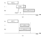
図17〜図19は本発明の実施例によって各衝突状況による衝突解決方法を説明するための例示的なタイミング図である。通信衝突及びランダム待機時間選択を含むISO/IEC 18000−6 Type C命令及び応答シーケンスの一連の例示を示し、提示された例示はすべての可能なシナリオの中で選択された一部の例である。二つのリーダ(R1とR2)と一つのタグ(T)の間で衝突が発生する場合のランダム遅延時間適用を例として挙げている。 17 to 19 are exemplary timing diagrams for explaining a collision resolution method according to each collision situation according to an embodiment of the present invention. Shows a series of examples of ISO / IEC 18000-6 Type C command and response sequence including communication collision and random wait time selection, and the examples presented are some examples selected in all possible scenarios . As an example, a random delay time is applied when a collision occurs between two readers (R 1 and R 2 ) and one tag (T).
本発明では、モバイルRFID環境で同時に発生する命令伝送の欠点を解消するために、ランダム待機時間を導入し、これをTRとして表示する。二つの競争するRFIDリーダが循環される(再)伝送試みを行って互いに邪魔する場合に発生する問題を避けるため、失敗したメッセージ伝送とその再伝送の間にランダム待機時間を適用する。図15を参照して一部説明したが、ランダム待機時間を適用するための前提条件が満足される場合にだけランダム待機時間が適用される。 In the present invention, in order to overcome the drawbacks of the instruction transmissions simultaneously generated in the mobile RFID environment, introducing a random wait time and displays it as a T R. In order to avoid problems that occur when two competing RFID readers interfere with each other by making repeated (re) transmission attempts, a random waiting time is applied between the failed message transmission and its retransmission. As described in part with reference to FIG. 15, the random waiting time is applied only when the precondition for applying the random waiting time is satisfied.
また、現在衝突のタイプを正確に決定することができないか、リーダに衝突診断機能が備えられていなければ、ランダム待機時間を適用するためのすべての前提条件が満足された状態で、タグ衝突調整の手順に指定された二つの連続したインベントリ命令の間、例えばISO/IEC 18000−6 Type Cの場合、QueryとQueryAdjustの間に、ランダム待機時間を適用することもできる。 Also, if the current collision type cannot be determined accurately or the reader does not have a collision diagnosis function, tag collision adjustment is performed with all the prerequisites for applying the random waiting time being satisfied. For example, in the case of ISO / IEC 18000-6 Type C, a random waiting time may be applied between two consecutive inventory commands specified in the above procedure.
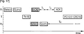
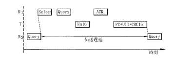
まず、図17はマルチリーダ対タグ衝突が発生した場合にランダム待機時間を適用するシーケンスを示す。リーダ(R1)はSelect命令とQuery命令を発行し、タグからRn16応答を受信した。リーダ(R1)は一つのタグをすでにシンギュレートし、リーダ(R2)は何のタグもシンギュレートすることができない状態である。そして、リーダ(R1)がACK命令を伝送したが、同時に伝送されたリーダ(R2)のSelect命令と衝突が発生した。衝突が発生したとき、リーダ(R1)はすでにタグ(T)を分離した状態である。よって、リーダ(R1)はISO/IEC 18000−6 Type Cのタイミング規約によって最終命令(ACK)を直ちに再伝送し、リーダ(R2)はランダム待機時間(TR)だけ遅延される。ここで、T3はリーダが他の命令を発行する前、T1の後に待機する時間を意味する。 First, FIG. 17 shows a sequence for applying a random waiting time when a multi-reader-to-tag collision occurs. The reader (R 1 ) issues a Select command and a Query command, and receives an Rn16 response from the tag. The reader (R 1 ) has already singulated one tag, and the reader (R 2 ) cannot singulate any tag. Then, the reader (R 1 ) transmitted the ACK command, but a collision occurred with the Select command of the reader (R 2 ) that was transmitted at the same time. When a collision occurs, the reader (R 1 ) has already separated the tag (T). Therefore, the leader (R 1 ) immediately retransmits the final command (ACK) according to the ISO / IEC 18000-6 Type C timing convention, and the leader (R 2 ) is delayed by a random waiting time (T R ). Here, T 3 means a time for the reader to wait after T 1 before issuing another command.
図15の手順を参照して説明すれば、リーダ(R2)は段階S1112、S1122、S1126、S1128、S1130、S1120を順に遂行してランダム待機時間の間にリーダを遅延させた後、命令を再伝送したものである。これにより、リーダ(R1)はPC+UII+CRC16でなるタグ応答を成功的に受信することができることになり、マルチリーダ対タグ衝突が解決される。 Referring to the procedure of FIG. 15, the leader (R 2 ) performs steps S1112, S1122, S1126, S1128, S1130, and S1120 in order to delay the leader during a random waiting time, and then issue a command. Retransmitted. As a result, the reader (R 1 ) can successfully receive a tag response of PC + UII + CRC16, and multi-reader-to-tag collision is resolved.
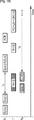
次に、図18はインベントリラウンドの初期段階で二つのリーダが衝突するリーダ対リーダ衝突を示す。リーダ(R1)がSelect命令とQuery命令を発行した後、二つのタグがいずれもタグをシンギュレートすることができなかった状態で、タグ(T)の応答Rn16とリーダ(R2)の命令Select及びQueryが衝突してリーダ対リーダ衝突が発生した。 Next, FIG. 18 shows a reader-to-reader collision where two leaders collide at the initial stage of the inventory round. After the reader (R 1 ) issues a Select instruction and a Query instruction, the response Rn16 of the tag (T) and the instruction Select of the reader (R 2 ) in a state where neither of the two tags can singulate the tag. And Query collided to generate a reader-to-reader collision.
したがって、リーダ(R1)とリーダ(R2)はいずれもランダム待機時間(TR)の間に遅延され、リーダ(R1)は以後にQueryAdjust命令とACK命令を伝送し、Rn16とPC+UII+CRC16の応答を成功的に受信することができることになり、リーダ対リーダ衝突が解決される。 Therefore, both the leader (R 1 ) and the leader (R 2 ) are delayed during the random waiting time (T R ), and the leader (R 1 ) subsequently transmits a QueryAdjust command and an ACK command, and Rn16 and PC + UII + CRC16 The response can be successfully received and the reader-to-reader collision is resolved.
また、図19はリーダ対リーダ衝突が発生したとき、リーダ(R1)がすでにタグを分離するほどに進行した場合に行われるシーケンスを示す。リーダ(R1)は一つのタグをすでにシンギュレートし、リーダ(R2)は何のタグもシンギュレートすることができない状態でリーダ対リーダ衝突が発生した。このような特別な場合、リーダ(R1)はT2の後にACKを再伝送し、リーダ(R2)はTRだけ遅延されることにより、リーダ対リーダ衝突が解決される。 FIG. 19 shows a sequence performed when the reader (R 1 ) has already progressed to the extent that the reader (R 1 ) has already separated the tag when a reader-reader collision occurs. The reader (R 1 ) has already singulated one tag, and the reader (R 2 ) has failed to singulate any tag and a reader-to-reader collision has occurred. In such cases special reader (R 1) is re-transmits an ACK after T 2, the reader (R 2) by being delayed by T R, the reader-to-reader collision is resolved.
次に、どの場合にランダム待機時間を適用するかについてさらに説明する。一般に、RFIDリーダは、セレクト、インベントリ、アクセスの三つの段階を持つ。現在のインベントリパス(pass)で何のタグもまだアクノリッジ(acknowledge)されなく(タグがシンギュレート(singulate)され、ACKを伝送したが、応答を受信することができない)インベントリされなかったら、タグセレクト段階またはタグインベントリ段階で命令を再伝送する前、ランダム待機時間だけリーダが遅延される。ここで、シンギュレーション(singulation)はタグのUIIを読み取るために占有されなかった応答スロットでタグを強要(force)することでタグを分離(separation)する手順を意味する。一方、リーダはタグアクセスの間には遅延されない。 Next, in which case the random waiting time is applied will be further described. Generally, an RFID reader has three stages: select, inventory, and access. If no tag has yet been acknowledged in the current inventory path (the tag is singulated, transmitted an ACK, but cannot receive a response), the tag selection phase Or the reader is delayed by a random waiting time before retransmitting the command in the tag inventory phase. Here, singulation refers to a procedure for separating a tag by forcing the tag in a response slot that is not occupied to read the UII of the tag. On the other hand, the reader is not delayed between tag accesses.
ランダム待機時間はデフォルトとして適用されてはいなく、リーダがインベントリラウンドの初期段階にある場合にだけ適用される。すなわち、タグをまだ分離しない場合にだけ適用される。そうでなければ、衝突する二つのリーダは衝突後にいずれも自動的に遅延され、短い伝送ブレーキの後にほぼ並列的に続いて命令を発行することができることになり、これは衝突(後続の衝突)を再び発生させるであろう。その代わりに、二つのリーダの中で一つだけがブロックされ、十分な時間だけ遅延されたら、その間に他のリーダは最終命令を再伝送することができ、その間にすべてのインベントリラウンドを終了することができることになる。 Random waiting time is not applied as a default, but only when the leader is in the early stages of the inventory round. That is, it applies only when the tag is not yet separated. Otherwise, the two colliding leaders will both be automatically delayed after the collision, and will be able to issue a command following the short transmission brake almost in parallel, which is a collision (subsequent collision) Will be generated again. Instead, if only one of the two readers is blocked and delayed for a sufficient amount of time, the other readers can retransmit the final command during that time, ending all inventory rounds in the meantime Will be able to.
このような方法により、本発明による再伝送パターンが重畳する可能性を減らすことができ、より古い(older)インベントリラウンドがより新規の(newer)インベントリラウンドより一般的に先に終了することができることになるので、公正な待機戦略を実施することができるようにする。 By such a method, the possibility of overlapping retransmission patterns according to the present invention can be reduced, and older inventory rounds can be terminated generally before newer inventory rounds. So that a fair waiting strategy can be implemented.
次に、本発明の実施例によって図4のランダム待機時間計算部1652がランダム待機時間を計算する手順について説明する。ランダム待機時間(TR)は性能を最大化させ後続衝突の可能性を最小化させることができるように選択されなければならない。したがって、平均的に良好な結果を達成するように、待機時間は最小再伝送待機時間(MinWaitTime)と最大再伝送待機時間(MaxWaitTime)に定義される範囲内でランダムに選択され、これがランダム待機時間として決定される。
Next, a procedure for the random standby
ランダム待機時間はFmin(MinWaitTime)とFmax(MaxWaitTime)に規定される基準値の間のランダム整数を選択することもでき、FminとFmaxによって与えられる値の間の時間値に応じたクロックサイクルの個数に応じた整数値を選択することもできる。 The random waiting time can be selected as a random integer between the reference values defined in Fmin (MinWaitTime) and Fmax (MaxWaitTime), and the number of clock cycles according to the time value between the values given by Fmin and Fmax. An integer value corresponding to can be selected.
一方、プロトコルデータユニット(PDU;Protocol Data Unit)が重畳することができる時間を競争区間(CP;Contention Period)と言う。プロトコルデータユニットはデータが伝送されるときの一定大きさのデータブロックを意味し、RFIDリーダまたはRFIDタグによって伝送されるすべての種類のデータパッケージで、リーダ命令及びタグ応答を含む。競争区間でリーダ命令またはタグ応答は脆弱であり、干渉によって破壊できる。タグインベントリの間に発行される典型的な命令シーケンスまたは単一プロトコルデータユニットの脆弱性を減少させるために、プロトコルデータユニットの持続時間(duration)に比例してランダム待機時間を選択することが好ましい。 On the other hand, a time during which a protocol data unit (PDU; Protocol Data Unit) can be overlapped is referred to as a competition period (CP). The protocol data unit means a data block of a certain size when data is transmitted, and includes reader commands and tag responses in all types of data packages transmitted by RFID readers or RFID tags. The leader command or tag response is fragile in the competitive section and can be destroyed by interference. In order to reduce the vulnerability of typical instruction sequences or single protocol data units issued during tag inventory, it is preferable to select a random waiting time proportional to the duration of the protocol data unit .
まず、ランダム待機時間の下限(lower threshold)である最小再伝送待機時間、つまりMinWaitTime(Fmin)は次の式によって計算される。
![]()
![]()
ここで、cは実際応用及び環境によって設定される定数値(動的に変更可能)であり、‘duration’は選択されたリンク速度(link rate)でエアインターフェース上で一定のプロトコルデータユニットを伝送するのに必要な時間を返還する関数である。これからは、cを‘待機時間パラメーター’という。待機時間パラメーターcは固定値であることもでき、動的に変更される値であることもできる。待機時間パラメーターcを固定すれば静的な再伝送待機時間を演算することができることになり、例えばc=1であることができる。longestExpectedPDUは‘予想最長プロトコルデータユニット’で、例えば図20に示すPC+UII+CRC16タグ応答である。 Where c is a constant value (which can be dynamically changed) set by the actual application and environment, and 'duration' transmits a certain protocol data unit over the air interface at the selected link rate. It is a function that returns the time required to do. From now on, c will be referred to as a “waiting time parameter”. The waiting time parameter c can be a fixed value or a dynamically changed value. If the waiting time parameter c is fixed, a static retransmission waiting time can be calculated, for example, c = 1. The longExpected PDU is an “expected longest protocol data unit”, for example, a PC + UII + CRC16 tag response shown in FIG.
このような方法でランダム待機時間の下限(最小再伝送待機時間)を決定するため、二つの競争するリーダ(R1とR2)が同一リンク速度を使用するし、計算されたランダム待機時間の下限が同一であれば、通信衝突によるそのインベントリ命令をR2がランダム遅延の後に再伝送する場合、同一プロトコルデータユニットによって後続衝突が発生しないというのを保証することができることになる。 In order to determine the lower limit of the random waiting time (minimum retransmission waiting time) in this way, two competing leaders (R 1 and R 2 ) use the same link speed and the calculated random waiting time If the lower limit is the same, if the inventory command by communication collision R 2 is re-transmitted after a random delay, it will be able to ensure that the that subsequent collision will not occur by the same protocol data unit.
図20は本発明の実施例による最小再伝送待機時間の意味を説明するためのタイミング図である。図20では、予想最長プロトコルデータユニットがACK命令に対するタグ応答であると仮定した場合を説明する。ここで、リーダ(R1)はすでにタグ(T)を現在応答スロットにシンギュレートしたが、タグ応答と衝突するQuery命令を発行したリーダ(R2)によってリーダ(R1)がタグをアクノリッジすることに失敗した。一般に、タグが衝突するときに伝送を中断しないため、後続衝突を回避するためには、少なくともタグ(T)がPC(Protocol control)、UII(Unique Item Identifier)、及びCRC16(Cyclic Redundancy Check16)でなるACKに対する応答を伝送するうちにはリーダ(R2)が遅延される必要があり、図20はリーダ(R2)が最小再伝送待機時間だけ遅延されて命令を再伝送する場合を示している。リーダ(R1)によって発行される他の命令と後続衝突が依然として発生することができるが、最大再伝送待機時間を最小再伝送待機時間より非常に大きい値に設定すればこのような問題点を最小化させることができるであろう。 FIG. 20 is a timing diagram for explaining the meaning of the minimum retransmission wait time according to the embodiment of the present invention. FIG. 20 illustrates a case where it is assumed that the longest expected protocol data unit is a tag response to the ACK command. Here, the reader (R 1 ) has already singulated the tag (T) into the current response slot, but the reader (R 1 ) acknowledges the tag by the reader (R 2 ) that issued the Query command that collides with the tag response. Failed. Generally, since transmission is not interrupted when a tag collides, in order to avoid a subsequent collision, at least the tag (T) is a PC (Protocol control), UII (Unique Item Identifier), and CRC16 (Cyclic Redundancy Check 16). made while transmitting a response to the ACK must reader (R 2) is delayed, FIG. 20 shows a case where the reader (R 2) to re-transmit command is delayed by a minimum retransmission wait time Yes. Subsequent collisions with other commands issued by the leader (R 1 ) can still occur, but this problem can be overcome by setting the maximum retransmission wait time to a value much greater than the minimum retransmission wait time. Could be minimized.
当該リーダがどの命令をサポートするか(強制(mandatory)命令、オプション命令)によって、かつ実際応用(インベントリのみ、またはインベントリ+タグアクセス)によって、予想最長プロトコルデータユニットはリーダ別に異なることができる。再伝送待機時間の上限または下限を計算するとき、リーダは次のインベントリラウンドで送信または受信すべき最長プロトコルデータユニット及び使用するエアインターフェース仕様によってサポートされる最長強制命令をいつも参照することが好ましい。 The expected longest protocol data unit can vary from reader to reader, depending on which commands the reader supports (mandatory commands, optional commands) and depending on the actual application (inventory only or inventory + tag access). When calculating the upper or lower limit of retransmission wait time, the reader preferably always refers to the longest protocol data unit to be transmitted or received in the next inventory round and the longest mandatory command supported by the air interface specification used.
リターンリンク(タグ応答)で伝送されるプロトコルデータユニットに関し、例えばQuery命令を発行することでインベントリラウンドの間にリーダが読み取るリターンリンク速度を、予想最長プロトコルデータユニットの決定のために使用することができる。例えば、UIIのバックスキャッターのように、受信すべきビット数を予め知ることができなくても、現在応用において可能な最大ビット数は予想することができる。これは、例えばエアインターフェース仕様がサポートするタグバックスキャッターの最大長さがもっと大きいとしても、現在応用がUIIの長さを96ビットまでサポートしたら、予想最長PDUを決定するのに96ビットを超える値は使用しないこともできることを意味する。 For protocol data units transmitted on the return link (tag response), the return link speed read by the reader during an inventory round, for example by issuing a Query command, may be used to determine the longest expected protocol data unit. it can. For example, even if the number of bits to be received cannot be known in advance as in the case of UII backscatter, the maximum number of bits possible in the current application can be predicted. For example, even if the maximum length of the tag backscatter supported by the air interface specification is larger, if the current application supports UII length up to 96 bits, it will exceed 96 bits to determine the expected longest PDU It means that the value can be omitted.
次に、ランダム待機時間の上限(upper threshold)である最大再伝送待機時間、つまりMaxWaitTime(Fmax)は次の式によって計算される。
![]()
![]()
ここで、cは最小再伝送待機時間の計算で使用された待機時間パラメーター、T1はリーダ伝送からタグ応答までの時間、T2はタグ応答からリーダ伝送までの時間であり、例えばISO/IEC 18000−6仕様に規定された値による。前記式の例では、リーダがSelect命令を伝送し、T4の時間の後にQuery命令を伝送し、タグがT1の時間の後にRN16を応答し、リーダがT2の時間の後にACK命令を伝送し、タグがT1の時間の後にUIIを応答する。UIIは、前述したように、PC、UII、及びCRC16を含む。 Here, c is a waiting time parameter used in the calculation of the minimum retransmission waiting time, T 1 is a time from the reader transmission to the tag response, and T 2 is a time from the tag response to the reader transmission. For example, ISO / IEC According to the value specified in the 18000-6 specification. In the example of the equation, reader transmits the Select command, and transmits the Query command after a time of T 4, the tag responds the RN16 after the time T 1, the reader is an ACK instruction after the time T 2 transmission, and the tag responds to UII after the time T 1. As described above, UII includes PC, UII, and CRC16.
最大再伝送待機時間の式に使用されたduration関数によって返還される結果は次のインベントリラウンドでリーダが使用するフォーワード及びリターンリンク速度及びACK命令に対するタグ応答の予想長さによって変わる。最小再伝送待機時間について説明したものと同様に、タグによってバックスキャッターされるUIIの長さを決定するために現在応用で可能な最大ビット数を予想して使用することができる。最大再伝送待機時間計算式に使用された‘Select+T4+Query+T1+RN16+T2+ACK+T1+UII’は例示的なもので、‘リーダ命令とタグ応答の総予想所要時間’に応じた値である。使用するエアインターフェース仕様及び応用によってこの値は変えることができる。タグアクセスが遂行されたら、関連した更なるリーダ命令とタグ応答を最大再伝送待機時間の計算に使用する。 The result returned by the duration function used in the maximum retransmission wait time formula depends on the forward and return link rates used by the reader in the next inventory round and the expected length of the tag response to the ACK command. Similar to that described for the minimum retransmission wait time, the maximum number of bits possible in the current application can be used in anticipation to determine the length of UII backscattered by the tag. “Select + T 4 + Query + T 1 + RN16 + T 2 + ACK + T 1 + UII” used in the maximum retransmission waiting time calculation formula is an example, and is a value corresponding to “total estimated time required for reader command and tag response”. This value can vary depending on the air interface specification and application used. Once tag access is performed, the associated further reader command and tag response are used to calculate the maximum retransmission wait time.
図21は本発明の実施例による最大再伝送待機時間の意味を説明するためのタイミング図である。図21は予想されるセレクト及びインベントリ段階の長さが‘Select+T4+Query+T1+RN16+T2+ACK+T1+UII’によって決まると仮定した場合を説明する。最大再伝送待機時間の式によって決定された基準値がリーダ(R1)とリーダ(R2)の間の衝突を潜在的に解決することができるというのを示す。 FIG. 21 is a timing diagram for explaining the meaning of the maximum retransmission wait time according to the embodiment of the present invention. FIG. 21 illustrates a case where it is assumed that the expected select and inventory stage length is determined by 'Select + T 4 + Query + T 1 + RN16 + T 2 + ACK + T 1 + UII'. The reference value determined by the maximum retransmission wait time equation indicates that a collision between leader (R 1 ) and leader (R 2 ) can potentially be resolved.
図22はISO/IEC 18000−6 Type C環境でのタイミングテーブルで、リンク速度と命令長さによってMinWaitTimeとMaxWaitTimeを計算する例を本タイミングテーブルを参照して説明する。最小再伝送待機時間及び最大再伝送待機時間は使用するリンク速度と伝送するプロトコルデータユニットによって決定される。テーブルでは、data0(02)に対してはTari=25μs、data1(12)に対しては1.5*Tariのシンボル長さに基づいてフォーワードリンク速度を仮定するとき、すべての関連したプロトコルデータユニットのタイミングを列挙している。また、40kbit/sのFM0エンコードされたデータがリターンリンクされると仮定した。これらの値は例示的なもので、使用するエアインターフェースによって変えることができる。 FIG. 22 is a timing table in the ISO / IEC 18000-6 Type C environment. An example of calculating MinWaitTime and MaxWaitTime according to the link speed and the command length will be described with reference to this timing table. The minimum retransmission wait time and the maximum retransmission wait time are determined by the link speed used and the protocol data unit to be transmitted. The table shows all relevant when assuming forward link speed based on a symbol length of Tari = 25 μs for data0 (0 2 ) and 1.5 * Tari for data1 (1 2 ). Lists the timing of protocol data units. In addition, it is assumed that 40 kbit / s FM0 encoded data is return-linked. These values are exemplary and can vary depending on the air interface used.
例えば、最小再伝送待機時間MinWaitTimeは、c*duration(longestExpectedPDU)=c*duration(UII)=c*3350によって計算される。cが1の場合、最小再伝送待機時間は3350μsである。また、最大再伝送待機時間MaxWaitTimeは、c*duration(Select+T4+Query+T1+RN16+T2+ACK+T1+UII)=c*(1375.0+125.0+962.5+250.0+550.0+75.0+662.5+250.0+3350.0)=c*7600によって計算される。cが1の場合、最大再伝送待機時間は7600μsである。本例では、タグアクセス段階がないと仮定したものであり、タグアクセスが遂行されたら、関連した更なるリーダ命令とタグ応答を最小再伝送待機時間と最大再伝送待機時間を計算するのに使用することができる。
For example, the minimum retransmission wait time MinWaitTime is calculated by c * duration (longestExpected PDU) = c * duration (UII) = c * 3350. When c is 1, the minimum retransmission waiting time is 3350 μs. Further, the maximum retransmission wait time MaxWaitTime is c * duration (Select + T 4 + Query + T 1 +
次に、本発明の実施例による適応型再伝送待機時間計算について説明する。前述した最小再伝送待機時間及び最大再伝送待機時間の式に使用された待機時間パラメーターc値を適応的に変更することで、実際応用での要求事項を最上に満足させ、実際応用シナリオによって性能と以後の衝突の間で最上のバランスを捜すため、待機時間パラメーターcが再伝送待機基準値の下限と上限に掛けられることによってランダム待機時間をチューニングするのに使用する。ここで、‘再伝送待機基準値’は、前述した最小再伝送待機時間及び最大再伝送待機時間の式で、cに掛けられる値であり、最小再伝送待機時間において予想最長プロトコルデータユニットに必要な時間が再伝送待機基準値の下限、最大再伝送待機時間においてリーダ命令とタグ応答の総予想所要時間が再伝送待機基準値の上限である。 Next, adaptive retransmission waiting time calculation according to an embodiment of the present invention will be described. By adaptively changing the waiting time parameter c value used in the above-mentioned minimum retransmission waiting time and maximum retransmission waiting time equations, the requirements in actual application are best satisfied, and the performance depends on the actual application scenario. In order to find the best balance between and subsequent collisions, the waiting time parameter c is used to tune the random waiting time by being multiplied by the lower and upper limits of the retransmission waiting reference value. Here, the “retransmission standby reference value” is a value multiplied by c in the above-described formula of the minimum retransmission standby time and the maximum retransmission standby time, and is required for the longest expected protocol data unit in the minimum retransmission standby time. Time is the lower limit of the retransmission standby reference value, and the total estimated required time of the reader command and tag response is the upper limit of the retransmission standby reference value at the maximum retransmission standby time.
最小再伝送待機時間と最大再伝送待機時間の式に使用される待機時間パラメーターcは、各インベントリラウンドの開始では1.0以上の値(c>=1.0)を持つ初期値に設定でき、タグがリーダによってアクノリッジされるまでは減少しない。これは、実際集団(population)の一つ以上のタグをすでにインベントリ及びアクセスしているかも知れない周辺のリーダを保護し、当該リーダによって発生する衝突可能性を減少させるのに好ましい。 The waiting time parameter c used in the minimum retransmission waiting time and maximum retransmission waiting time expressions can be set to an initial value having a value of 1.0 or more (c> = 1.0) at the start of each inventory round. It does not decrease until the tag is acknowledged by the reader. This is preferred to protect peripheral readers who may already have inventoried and accessed one or more tags of the population, and to reduce the likelihood of collisions caused by those readers.
タグがリーダによって成功的に感知された後には、追加の制限なしに残ったインベントリラウンド期間の間に待機時間パラメーターcを変更することができる。すなわち、待機時間パラメーターcは使用者の判断によっていつでも増加または減少できる。もし、待機時間パラメーターc値を固定したら、静的再伝送待機時間を演算することができる。 After the tag is successfully sensed by the reader, the waiting time parameter c can be changed during the remaining inventory round period without additional restrictions. That is, the waiting time parameter c can be increased or decreased at any time according to the judgment of the user. If the waiting time parameter c value is fixed, the static retransmission waiting time can be calculated.
この際、各インベントリラウンドの開始ではc値を制限することにより、再伝送待機時間に対する最初基準値を制限することは、チャネル利用に対する公正な手順を遂行するのに役立つ。タグ集団の中で一つ以上のタグをすでに感知しようとしているリーダはそのインベントリラウンドを終了するために小さな待機時間を持つことになり、その間に活性化された新しいリーダは最初cの値にあたるデフォルト設定を使用することになり、低いデューティサイクルを持つことになる。 Here, limiting the initial reference value for retransmission wait time by limiting the c value at the start of each inventory round helps to perform a fair procedure for channel utilization. Readers already trying to sense one or more tags in the tag population will have a small waiting time to finish their inventory round, while new readers activated during that time will default to the value of c The setting will be used and will have a low duty cycle.
エアインターフェース仕様によって使用者がリンク速度を規定することができるので、二つの競争するリーダが互いに異なるリンク速度で動作することができる。この場合、リーダ(R1)とリーダ(R2)によって計算される最小及び最大再伝送待機時間の間に差があり得る。よって、再発する(recurrent)後続衝突の場合にパラメーターcを調整することが必要である。反対に、観察される衝突の数がずっと小さく維持されたら、全体性能の向上のために同一パラメーターを使用することもできる。インベントリラウンドの間に待機時間パラメーターcを変更する方法について以下に詳細に説明する。 Because the air interface specification allows the user to define the link speed, two competing leaders can operate at different link speeds. In this case, there may be a difference between the minimum and maximum retransmission wait times calculated by the leader (R 1 ) and the leader (R 2 ). Therefore, it is necessary to adjust the parameter c in case of a recurring subsequent collision. Conversely, if the number of observed collisions is kept much smaller, the same parameters can be used to improve overall performance. A method for changing the waiting time parameter c during the inventory round will be described in detail below.
図23は待機時間パラメーターcを現在衝突の比率によって動的に変更する手順を示すフローチャートである。待機時間パラメーターcは最小再伝送待機時間及び最大再伝送待機時間の計算に使用されるパラメーターで、再伝送待機基準値(threshold)に掛けられる値である。現在衝突の比率(collision percentage)は例えばリーダの命令当たり衝突の平均回数である。 FIG. 23 is a flowchart showing a procedure for dynamically changing the waiting time parameter c according to the ratio of the current collision. The waiting time parameter c is a parameter used to calculate the minimum retransmission waiting time and the maximum retransmission waiting time, and is a value multiplied by the retransmission waiting reference value (threshold). The current collision percentage is, for example, the average number of collisions per reader command.
段階S1900は新しいインベントリラウンドの開始を意味する。インベントリラウンドが始まれば、段階S1902で待機時間パラメーターcを初期値に設定する。本例ではcの初期値を1.0に設定する。この初期値は少なくとも一つのタグがアクノリッジされるまでは変更されない。 Step S1900 means the start of a new inventory round. If the inventory round starts, the waiting time parameter c is set to an initial value in step S1902. In this example, the initial value of c is set to 1.0. This initial value is not changed until at least one tag is acknowledged.
次に、段階S1904に進みタグがアクノリッジされたか否かを判断する。段階S1904での判断結果、タグがまだアクノリッジされなかったら、段階S1902に帰り、待機時間パラメーターcを初期値に維持するかあるいは初期値にリセットする。段階S1904での判断結果、タグがアクノリッジされたら段階S1906に進む。段階S1906では、現在の衝突の比率(percentage)が衝突の比率基準値(threshold)未満であるかを判断する。段階S1906での判断結果、現在の衝突の比率が衝突の比率基準値未満であれば、段階S1908に進み待機時間パラメーターc値をパラメーター変更ファクターfだけ減少させる。すなわち、一番目のタグ感知(アクノリッジ)の後、衝突の比率が予め定義された基準値より低ければ、性能向上のためにファクターfだけcを減少させる。 In step S1904, it is determined whether the tag is acknowledged. If it is determined in step S1904 that the tag has not been acknowledged yet, the process returns to step S1902, and the waiting time parameter c is maintained at the initial value or reset to the initial value. If the tag is acknowledged as a result of the determination in step S1904, the process proceeds to step S1906. In step S1906, it is determined whether the current collision ratio is less than the collision ratio reference value (threshold). If it is determined in step S1906 that the current collision ratio is less than the collision ratio reference value, the process proceeds to step S1908 to decrease the waiting time parameter c value by the parameter change factor f. That is, after the first tag detection (acknowledgement), if the collision rate is lower than a predefined reference value, c is decreased by a factor f to improve performance.
段階S1906での判断結果、現在の衝突の比率が衝突の比率基準値未満でなければ、段階S1910に進み現在の衝突の比率が衝突の比率基準値を超えるかを判断する。衝突の比率が予め定義された基準値より高ければ、段階S1912に進みcをファクターfだけ増加させて平均再伝送待機時間を延長させることで、後続衝突の確率を減少させる。パラメーター変更ファクターfの値は実際状況によって変わることができ、応用の必要に合うように選択されなければならない。一般に、パラメーター変更ファクターfを0.1と1.0の間の値にすることができ、固定値でなく動的に変更される値にすることも可能である。 If it is determined in step S1906 that the current collision ratio is not less than the collision ratio reference value, the process proceeds to step S1910 to determine whether the current collision ratio exceeds the collision ratio reference value. If the collision rate is higher than the predefined reference value, the process proceeds to step S1912 to increase the average retransmission waiting time by increasing c by a factor f, thereby reducing the probability of subsequent collisions. The value of the parameter change factor f can vary depending on the actual situation and must be selected to suit the needs of the application. In general, the parameter change factor f can be a value between 0.1 and 1.0, and can be a dynamically changed value instead of a fixed value.
段階S1910での判断結果、衝突の比率が衝突の比率基準値を超えなければ(衝突の比率が基準値と同一であれば)cを変更せずに段階S1904に復帰する。本実施例で言及する衝突の比率基準値は実際応用シナリオによって変わる。例えば、バス停のように近くに位置するモバイルRFID使用者の数が大きいと予想される場合、基準値を大きく設定することができ、例えば家庭でRFIDを使用する場合のように使用者の数が小さいと予想される場合、基準値を小さく設定することができる。一般に、“衝突の比率(collision percentage)”という用語は干渉によって逃した、つまりリーダが成功的に復号化することができなかったタグ応答の比率を示すと言える。 If it is determined in step S1910 that the collision ratio does not exceed the collision ratio reference value (if the collision ratio is the same as the reference value), the process returns to step S1904 without changing c. The collision ratio reference value referred to in this embodiment varies depending on the actual application scenario. For example, if the number of mobile RFID users located near a bus stop is expected to be large, the reference value can be set to a large value. For example, the number of users is low when using RFID at home. If it is expected to be small, the reference value can be set small. In general, it can be said that the term “collation percentage” refers to the ratio of tag responses missed by interference, ie, the reader could not successfully decode.
図24は図23の手順を確張したもので、待機時間パラメーターcを現在衝突の比率及びタイムアウトの比率によって動的に変更する手順を示すフローチャートである。本実施例では、レシーバータイムアウトの比率(応答されなかった(unanswered)リーダ命令の比率)を予定されたタイムアウトの比率基準値と結合して使用することを説明する。現在の衝突状況によって再発するレシーバータイムアウトがある場合、待機時間パラメーターcを動的に増加させるかあるいはリセットする。 FIG. 24 is a flowchart showing the procedure for dynamically changing the waiting time parameter c according to the current collision ratio and the timeout ratio, extending the procedure of FIG. In the present embodiment, it will be described that the receiver timeout ratio (the ratio of unanswered reader commands) is used in combination with the scheduled timeout ratio reference value. If there is a receiver timeout that recurs due to the current collision situation, the waiting time parameter c is dynamically increased or reset.
図24に示すすべての条件はリーダ側を参照している。例えば、段階S2006の‘Collision Visible’(衝突が観察できるか)は受信したビットストリームを評価してリーダで衝突を感知することができることを意味する。これはタグ側でだけ明かすことができるマルチリーダ対タグ衝突を含まないものである。さらに、リーダ側で現れるレシーバータイムアウトはいつも現在応答スロットにマッチングされるタグがないため発生するものではなく、隠されたマルチリーダ対タグ衝突を示すこともできることを考慮しなければならない。したがって、本実施例では、段階S2018の‘タイムアウトの比率が基準値を超えたか’の条件と段階S2012の‘衝突の比率が基準値を超えたかか’の条件が有機的に結合されている。 All conditions shown in FIG. 24 refer to the reader side. For example, 'Collation Visible' in step S2006 means that the received bitstream can be evaluated and the reader can detect the collision. This does not include multi-reader-to-tag collisions that can only be revealed on the tag side. Furthermore, it must be taken into account that the receiver timeout appearing on the reader side does not always occur because there is no tag currently matched in the response slot, and can also indicate a hidden multi-reader-to-tag collision. Therefore, in the present embodiment, the condition “whether the timeout ratio exceeds the reference value” in step S2018 and the condition “whether the collision ratio exceeds the reference value” in step S2012 are organically combined.
‘タイムアウトの比率(percentage)’は応答しなかったリーダ命令の比率を示す。例えば、リーダが四つの命令を伝送し、そのうち二つに対してだけ(有効または無効の)応答を受信したら、タイムアウトの比率は0.5である。Selectのようにタグ応答を要しない命令はタイムアウトの比率を計算するのに使用されない。タイムアウトの比率基準値は実際応用によって変わり、シナリオ別に変わることになる。 'Timeout ratio (percentage)' indicates the ratio of reader commands that have not responded. For example, if the reader transmits four commands and receives responses (valid or invalid) for only two of them, the timeout ratio is 0.5. Instructions that do not require a tag response, such as Select, are not used to calculate the timeout ratio. The time-out ratio reference value varies depending on the actual application and varies depending on the scenario.
本実施例は、レシーバータイムアウトが観察されたとき衝突がすでにその頂点に到達していたら、レシーバータイムアウトによる再伝送が現在の衝突状況をそれ以上悪化させないことを保証する。また、現在のタイムアウトの比率がタイムアウトの比率基準値より低くなれば、待機時間パラメーターcはプロトコル性能のためにその初期値に再びリセットされる。本実施例での用語‘衝突’はすべての形態の衝突を意味し、本発明による3種の衝突の間に何の差も発生させない。 This embodiment ensures that retransmissions due to receiver timeouts will not worsen the current collision situation if the collision has already reached its peak when a receiver timeout is observed. Also, if the current timeout ratio falls below the timeout ratio reference value, the waiting time parameter c is reset again to its initial value for protocol performance. The term 'collision' in this embodiment means all forms of collision and does not cause any difference between the three types of collision according to the present invention.
図24で、段階S2000は新しいインベントリラウンドの開始を意味する。インベントリラウンドが始まれば、段階S2002で待機時間パラメーターcを初期値に設定する。本例では、cの初期値を1.0に設定する。この初期値は少なくとも一つのタグがアクノリッジされるまでは変更されない。 In FIG. 24, step S2000 means the start of a new inventory round. If the inventory round starts, the waiting time parameter c is set to an initial value in step S2002. In this example, the initial value of c is set to 1.0. This initial value is not changed until at least one tag is acknowledged.
次に、段階S2004に進みタグがアクノリッジされたかを判断する。段階S2004での判断結果、タグがまだアクノリッジされなかったら、段階S2002に復帰し、待機時間パラメーターcを初期値に維持する。段階S2004での判断結果、タグがアクノリッジされたら、段階S2006に進む。段階S2006では、衝突が観察可能(visible)であるかを判断する。すなわち、受信したビットストリームを評価し、リーダで衝突を感知することができるかを判断する。衝突が観察可能であると判断されれば、段階S2008に進み現在の衝突の比率が衝突の比率基準値未満であるかを判断する。段階S2008での判断結果、現在の衝突の比率が衝突の比率基準値未満であれば、段階S2010に進み待機時間パラメーターc値をパラメーター変更ファクターfだけ減少させる。 In step S2004, it is determined whether the tag has been acknowledged. If the result of determination in step S2004 is that the tag has not yet been acknowledged, the process returns to step S2002, and the waiting time parameter c is maintained at the initial value. If the tag is acknowledged as a result of the determination in step S2004, the process proceeds to step S2006. In step S2006, it is determined whether the collision is observable. That is, the received bit stream is evaluated to determine whether or not the reader can detect a collision. If it is determined that the collision can be observed, the process proceeds to step S2008 to determine whether the current collision ratio is less than the collision ratio reference value. If it is determined in step S2008 that the current collision ratio is less than the collision ratio reference value, the process proceeds to step S2010, and the waiting time parameter c value is decreased by the parameter change factor f.
段階S2008での判断結果、現在の衝突の比率が衝突の比率基準値未満でなければ、段階S2012に進み現在の衝突の比率が衝突の比率基準値を超えるかを判断する。衝突の比率が予定された基準値より高ければ、段階S2014に進みcをファクターfだけ位増加させ、平均再伝送待機時間を延長させることにより、後続衝突確率を減少させる。段階S2012での判断結果、衝突の比率が衝突の比率基準値を超えなかったら(衝突の比率が基準値と同一であれば)cを変更せずに段階S2006に復帰する。 If the current collision ratio is not less than the collision ratio reference value as a result of the determination in step S2008, the process proceeds to step S2012 to determine whether the current collision ratio exceeds the collision ratio reference value. If the collision ratio is higher than the predetermined reference value, the process proceeds to step S2014, where c is increased by a factor f, and the average retransmission waiting time is extended to reduce the subsequent collision probability. If it is determined in step S2012 that the collision ratio does not exceed the collision ratio reference value (if the collision ratio is the same as the reference value), the process returns to step S2006 without changing c.
一方、段階S2006での判断結果、衝突が観察可能でない判断された場合、段階S2016に進みタイムアウトが観察可能であるかを判断する。タイムアウトが観察可能でない場合には、段階S2002に進みcを初期値にリセットするが、タイムアウトが観察可能である場合には、段階S2018に進み、タイムアウトの比率が予定されたタイムアウトの比率基準値を超えたかを判断する。段階S2018で、タイムアウトの比率が基準値以下であると判断されれば、段階S2002に復帰するが、タイムアウトの比率が基準値を超えたと判断されれば、段階S2012に進み衝突の比率と基準値を比較する。このような手順をインベントリラウンドごとに繰り返し行うことにより、再伝送待機時間を適応的に変更設定することができることになる。 On the other hand, if it is determined in step S2006 that the collision is not observable, the process proceeds to step S2016 to determine whether the timeout is observable. If the time-out is not observable, the process proceeds to step S2002 and c is reset to the initial value. If the time-out is observable, the process proceeds to step S2018, and the time-out ratio reference value for which the time-out ratio is scheduled is set. Judge whether it exceeded. If it is determined in step S2018 that the timeout ratio is equal to or less than the reference value, the process returns to step S2002. If it is determined that the timeout ratio exceeds the reference value, the process proceeds to step S2012, and the collision ratio and the reference value are obtained. Compare By repeating such a procedure every inventory round, the retransmission waiting time can be adaptively changed and set.
前述した本発明のモバイルRFIDリーダに関するエアインターフェース仕様は、静的(static)RFIDリーダに使用するために開発された従来のエアインターフェース仕様に結合されて適用することもできる。本発明は、前述した諸実施例の構成と方法に限定的に適用可能なものではなく、諸実施例は、多様な変形ができるように各実施例の全部または一部が選択的に組み合せられて構成することもできる。 The air interface specification for the mobile RFID reader of the present invention described above can also be applied in combination with a conventional air interface specification developed for use in a static RFID reader. The present invention is not limited to the configurations and methods of the above-described embodiments, and all or a part of the embodiments can be selectively combined so that various modifications can be made. It can also be configured.
本発明はモバイルRFIDシステムに使用されることにより、衝突の可能性を減少させ、衝突が発生したとき、衝突の発生原因を把握し、その原因及び様相によって適応的に衝突を解決することができるので、モバイルRFIDの底辺拡大に大きく寄与するであろう。 The present invention is used in a mobile RFID system to reduce the possibility of collision, and when a collision occurs, the cause of the collision can be grasped and the collision can be resolved adaptively according to the cause and aspect. Therefore, it will greatly contribute to the expansion of the bottom of mobile RFID.
Claims (16)
前記衝突タイプに基づいて、コマンドを再伝送するか否かを判断する状況別コマンド再伝送部;及び
コマンド再伝送のためのランダム待機時間を計算するランダム待機時間計算部を含み、
前記ランダム待機時間計算部は、再伝送待機基準値の下限および上限に待機時間パラメータを掛けた値に応じて決定される最小再伝送待機時間と最大再伝送待機時間との間で、ランダムにランダム待機時間を選択し、
前記ランダム待機時間計算部は、前記待機時間パラメータを、インベントリラウンドが始まるときに、所定の初期値に設定し、タグをアクナリッジするまでは前記待機時間パラメータを減少させないことを特徴とする、RFIDリーダ装置。Analyzing the data of the received signal, to check for collision of the received signal, the collision diagnosis unit for diagnosing the collision type on the basis of the analysis result of the received signal data;
A command retransmission unit for each situation for determining whether to retransmit a command based on the collision type; and a random waiting time calculation unit for calculating a random waiting time for command retransmission,
The random standby time calculation unit randomly selects between a minimum retransmission standby time and a maximum retransmission standby time determined according to a value obtained by multiplying a lower limit and an upper limit of a retransmission standby reference value by a standby time parameter. Select the waiting time ,
The RFID reader is characterized in that the random waiting time calculation unit sets the waiting time parameter to a predetermined initial value when an inventory round starts, and does not decrease the waiting time parameter until the tag is acknowledged. apparatus.
状況別コマンド再伝送部が、前記衝突タイプに基づいて、コマンドを再伝送するか否かを判断するコマンド再伝送判断段階;及び
ランダム待機時間計算部が、コマンドの再伝送のためのランダム待機時間を計算するランダム待機時間計算段階を含み、
前記ランダム待機時間計算段階は、再伝送待機基準値の下限および上限に待機時間パラメータを掛けた値に応じて決定される最小再伝送待機時間と最大再伝送待機時間との間で、ランダムにランダム待機時間を選択し、前記待機時間パラメータを、インベントリラウンドが始まるときに、所定の初期値に設定し、タグをアクナリッジするまでは前記待機時間パラメータを減少させないことを特徴とする、RFIDリーダ装置の制御方法。 Collision diagnosis unit analyzes the data of the received signal, collision diagnosis stage to check for collision of the received signal, to diagnose a collision type based on the analysis result of the received signal data;
Situation-specific command retransmission portion, based on the collision type, the command retransmission determination step determines whether to retransmit the command; and random wait time calculation unit, a random waiting time for retransmission of the command Including a random waiting time calculation stage to calculate
The random waiting time calculation step is performed at random between a minimum retransmission waiting time and a maximum retransmission waiting time determined according to a value obtained by multiplying a lower limit and an upper limit of a retransmission waiting reference value by a waiting time parameter. The RFID reader device is characterized in that a waiting time is selected , the waiting time parameter is set to a predetermined initial value when an inventory round starts, and the waiting time parameter is not decreased until the tag is acknowledged . Control method.
Applications Claiming Priority (3)
| Application Number | Priority Date | Filing Date | Title |
|---|---|---|---|
| US3580508P | 2008-03-12 | 2008-03-12 | |
| US61/035,805 | 2008-03-12 | ||
| PCT/KR2009/001254 WO2009113826A2 (en) | 2008-03-12 | 2009-03-12 | Rfid interrogator calculating adaptive retransmisison wait time and control method thereof |
Publications (2)
| Publication Number | Publication Date |
|---|---|
| JP2011513875A JP2011513875A (en) | 2011-04-28 |
| JP5150737B2 true JP5150737B2 (en) | 2013-02-27 |
Family
ID=41065676
Family Applications (1)
| Application Number | Title | Priority Date | Filing Date |
|---|---|---|---|
| JP2010550601A Expired - Fee Related JP5150737B2 (en) | 2008-03-12 | 2009-03-12 | RFID reader device for calculating adaptive retransmission waiting time and control method thereof |
Country Status (4)
| Country | Link |
|---|---|
| US (1) | US8773242B2 (en) |
| JP (1) | JP5150737B2 (en) |
| KR (1) | KR101489213B1 (en) |
| WO (1) | WO2009113826A2 (en) |
Families Citing this family (8)
| Publication number | Priority date | Publication date | Assignee | Title |
|---|---|---|---|---|
| US9734645B2 (en) * | 2010-10-15 | 2017-08-15 | The Chamberlain Group, Inc. | Method and apparatus pertaining to message-based functionality |
| KR101307491B1 (en) * | 2011-10-18 | 2013-09-11 | 성균관대학교산학협력단 | Anti-collision system and method with moving tags in rfid systems |
| KR101323787B1 (en) * | 2012-02-10 | 2013-10-31 | 삼성중공업 주식회사 | Method of transmitting tag information of radio frequency identification tag, and tag position-tracking system |
| JP6453752B2 (en) * | 2014-11-28 | 2019-01-16 | 株式会社小松製作所 | Communication system and work vehicle |
| KR102458563B1 (en) | 2018-02-12 | 2022-10-28 | 한국전자통신연구원 | Communication method and communication device using ambient backscatter communication |
| US11243853B2 (en) | 2019-11-26 | 2022-02-08 | International Business Machines Corporation | Service retry collision prevention using prime numbers |
| CN113015133B (en) * | 2021-02-08 | 2023-04-07 | 北京千方科技股份有限公司 | Multi-antenna signal collision prevention method and device applied to RSU (radio side Unit) equipment of ETC (electronic toll Collection) |
| CN120614700A (en) * | 2024-03-08 | 2025-09-09 | 华为技术有限公司 | Communication method and device |
Family Cites Families (6)
| Publication number | Priority date | Publication date | Assignee | Title |
|---|---|---|---|---|
| US5365551A (en) * | 1992-12-15 | 1994-11-15 | Micron Technology, Inc. | Data communication transceiver using identification protocol |
| US6813260B1 (en) * | 2000-03-16 | 2004-11-02 | Ericsson Inc. | Systems and methods for prioritized access in a contention based network |
| US7009496B2 (en) * | 2002-04-01 | 2006-03-07 | Symbol Technologies, Inc. | Method and system for optimizing an interrogation of a tag population |
| KR100641380B1 (en) * | 2006-01-12 | 2006-11-02 | 주식회사 디앤에스 테크놀로지 | How to Prevent Reader Period Collision in Wireless Tag System |
| JP2007241392A (en) | 2006-03-06 | 2007-09-20 | Fujitsu Ltd | Tag communication device and tag communication method |
| KR100858053B1 (en) | 2006-05-10 | 2008-09-10 | 한국전자통신연구원 | A Passive RFID Reader and Operation Control Method |
-
2009
- 2009-03-12 KR KR20090021372A patent/KR101489213B1/en not_active Expired - Fee Related
- 2009-03-12 WO PCT/KR2009/001254 patent/WO2009113826A2/en not_active Ceased
- 2009-03-12 US US12/922,054 patent/US8773242B2/en active Active
- 2009-03-12 JP JP2010550601A patent/JP5150737B2/en not_active Expired - Fee Related
Also Published As
| Publication number | Publication date |
|---|---|
| WO2009113826A3 (en) | 2010-04-08 |
| KR20090097829A (en) | 2009-09-16 |
| US20110006884A1 (en) | 2011-01-13 |
| US8773242B2 (en) | 2014-07-08 |
| WO2009113826A2 (en) | 2009-09-17 |
| KR101489213B1 (en) | 2015-02-04 |
| JP2011513875A (en) | 2011-04-28 |
Similar Documents
| Publication | Publication Date | Title |
|---|---|---|
| JP5094979B2 (en) | RFID reader device for retransmitting command according to collision situation and control method thereof | |
| JP5150737B2 (en) | RFID reader device for calculating adaptive retransmission waiting time and control method thereof | |
| EP1977375B1 (en) | Method of preventing collisions between rfid readers in rfid system | |
| KR101502755B1 (en) | RFID reader having collision type identification function and control method thereof | |
| CA2700247C (en) | Optimizing rfid reader duty cycle or power to preserve battery life | |
| US8477017B2 (en) | Method, system, and integrated circuit for communication in RFID or remote sensor systems | |
| KR101589526B1 (en) | Tag anti-collision method, reader apparatus and system for rfid systems with multi-packet reception capability | |
| US20090179738A1 (en) | Tag reading device | |
| EP2230625A1 (en) | Binary tree method for multi-tag anti-collision | |
| EP2987113B1 (en) | Defining a radio frequency identification read area | |
| CN115136139A (en) | Tag identification and inventory method, device, reader, medium, and computer program | |
| US9165169B2 (en) | Method for data communication between a base station and a transponder | |
| KR20090049346A (en) | Collision Detection System and Method of RFID Tag | |
| KR100858053B1 (en) | A Passive RFID Reader and Operation Control Method | |
| US20090134977A1 (en) | Method and apparatus for RFID device coexistance | |
| US8111672B2 (en) | Method for data communication between a base station and a transponder | |
| KR100863186B1 (en) | Slot Random Collision Avoidance Method for RDFID and RDF Tag for the Same | |
| Nguyen et al. | Tweaked binary tree algorithm to cope with capture effect and detection error in RFID systems | |
| Chin et al. | Aloha‐Based Protocols | |
| WO2003085843A2 (en) | Transponder-based communication systems |
Legal Events
| Date | Code | Title | Description |
|---|---|---|---|
| A977 | Report on retrieval |
Free format text: JAPANESE INTERMEDIATE CODE: A971007 Effective date: 20120709 |
|
| A131 | Notification of reasons for refusal |
Free format text: JAPANESE INTERMEDIATE CODE: A131 Effective date: 20120724 |
|
| A521 | Request for written amendment filed |
Free format text: JAPANESE INTERMEDIATE CODE: A523 Effective date: 20121005 |
|
| TRDD | Decision of grant or rejection written | ||
| A01 | Written decision to grant a patent or to grant a registration (utility model) |
Free format text: JAPANESE INTERMEDIATE CODE: A01 Effective date: 20121102 |
|
| A61 | First payment of annual fees (during grant procedure) |
Free format text: JAPANESE INTERMEDIATE CODE: A61 Effective date: 20121203 |
|
| R150 | Certificate of patent or registration of utility model |
Free format text: JAPANESE INTERMEDIATE CODE: R150 |
|
| FPAY | Renewal fee payment (event date is renewal date of database) |
Free format text: PAYMENT UNTIL: 20151207 Year of fee payment: 3 |
|
| LAPS | Cancellation because of no payment of annual fees |