JP4133242B2 - Non-contact IC card, response method, and program thereof - Google Patents
Non-contact IC card, response method, and program thereof Download PDFInfo
- Publication number
- JP4133242B2 JP4133242B2 JP2002329143A JP2002329143A JP4133242B2 JP 4133242 B2 JP4133242 B2 JP 4133242B2 JP 2002329143 A JP2002329143 A JP 2002329143A JP 2002329143 A JP2002329143 A JP 2002329143A JP 4133242 B2 JP4133242 B2 JP 4133242B2
- Authority
- JP
- Japan
- Prior art keywords
- response
- time slot
- card
- contact
- slot
- Prior art date
- Legal status (The legal status is an assumption and is not a legal conclusion. Google has not performed a legal analysis and makes no representation as to the accuracy of the status listed.)
- Expired - Lifetime
Links
Images


Landscapes
- Credit Cards Or The Like (AREA)
Description
【0001】
【発明の属する技術分野】
【0002】
本発明は、非接触ICカード、応答方法、及びそのプログラムに関し、詳しくは、リーダライタより送信されるリクエストに対してタイムスロットを用いて応答する非接触ICカード、応答方法、及びそのプログラムに関する。
【従来の技術】
【0003】
従来、電磁誘導方式等を用いてデータの授受を行なう非接触ICカードと当該非接触ICカードを認識するリーダライタとの間の通信には、タイムスロット方式が採用されている。これは、複数の非接触ICカードが同時にリーダライタの通信可能エリア内に存在し、リーダライタからのポーリングに対して複数の非接触ICカードが同時に応答した場合、当該応答に用いられる各レスポンス信号が衝突して何れの非接触ICカードもリーダライタと正常に通信することができなくなるためである。
【0004】
上記タイムスロット方式の通信方法を以下に説明する。
【0005】
(1)まずリーダライタは非接触ICカードの存在を確認するために、リクエストとして初期応答リクエストコマンドを非接触ICカードに送信する。上記初期応答リクエストコマンドには、非接触ICカードが行なう初期応答のタイミングの制御に必要な「スロット数」、又は「スロット数」を計算する為に必要な値が含まれる。
【0006】
(2)上記非接触ICカードは、上記初期応答リクエストコマンドを受信後、特定時間から設けられるタイムスロット(1〜「スロット数」)へ上記初期応答を返す。応答に用いるタイムスロット、即ちタイミングは、非接触ICカード自身が乱数で決定する。
【0007】
(3)上記リーダライタは、複数の非接触ICカードが同一のタイムスロットを選択した際に起こる初期応答の衝突を検出した場合、再度上記初期応答リクエストを送信する。
【0008】
(4)上記リーダライタは、すべての非接触ICカードからの初期応答を衝突なしに受信することですべての非接触ICカードの認識をし、当該カードの識別のためのシーケンスを完了する。
【0009】
以上の処理を、図16〜図18を用いてさらに詳しく説明する。尚、以下に示すのは、近接型非接触ICカードの国際規格ISO/IEC14443に適応した場合の非接触ICカードの処理である。
【0010】
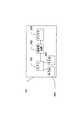
ISO/IEC14443は例えば、非接触テレホンカードなどに適応できる。さらに具体的に、図16に示すように、公衆電話として機能するリーダライタ1600にテレホンカードとしての機能を有する非接触ICカード1601、1602を同時に差し込んだ(近接させた)場合を想定する。
【0011】
ISO/IEC14443の非接触ICカードの認識システムにおいては、以下の手順で非接触ICカードの認識が行われる。
【0012】
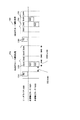
まず、公衆電話であるリーダライタ1600が初期応答リクエスト(リクエスト)を送信する。当該初期応答リクエストは、図18に示されるフォーマットになっており、初期応答リクエスト1801を構成するPARAM1802内の8bitのうち、bit1〜bit3の3bit1803を用いてタイムスロット数(N)を非接触ICカードに通知する。尚、APf1804は、初期要求コマンドを示すヘッダであり、AFI1805は非接触ICカードの適応クラスを示す。又、CRC(Cyclic Redundancy Check)1806はAPf〜PARAMまでのCRCである。
【0013】
尚、非接触ICカードは1〜NまでのN個のスロットで応答するが、今回の説明ではタイムスロット数(N)を4として説明を行う。即ち、初期応答リクエストに対して非接触ICカード1601及び1602は、1〜4までのタイムスロットのうち一つを選択し、初期応答を行う。
【0014】
図17で示す一回目のカード識別処理1701において、まずリーダライタ1600から初期応答リクエストR1〔REQB〕(1702)を送信する。当該初期応答リクエストR1(1702)に対して非接触ICカード1601及び1602が、乱数としてそれぞれ「1」を生成したときには、タイムスロット1(1704)内の初期応答〔ATQB〕A21、A31でそれぞれ応答する。この場合、上記非接触ICカード1601、1602共同一のタイミングで初期応答を応答するため、リーダライタ1600は、非接触ICカードの初期応答の衝突を検出する。したがって、再度、識別処理を再開する。
【0015】
二回目の識別処理1707において、リーダライタ1600から初期応答リクエストR2(1703)を送信する。初期応答リクエストに対して非接触ICカード1601及び1602が、乱数として「3」、および「2」を生成したときには、タイムスロット3(1705)内のパケットA22、およびタイムスロット2(1706)内のパケットA32で応答する。この場合、リーダライタ1600は衝突を検出しないため、すべての非接触ICカードの識別を行うことができ、識別処理を完了する。以上がISO/IEC14443の規定に従った、非接触ICカードのカード識別処理である。尚、ISO/IEC14443の規定では、初期応答リクエストコマンドを受け取ってから、非接触ICカードがタイムスロット1で応答する場合の時間を302μsecと規定し、また、1つのタイムスロットの期間(時間)は2266μsecと規定している。つまり、リーダライタ1600から初期応答リクエストを受信して、初期応答を送信するまでのタイミング(μsec)は、以下の計算式(式1)により与えられる。
【0016】
タイミング(μsec)=302μsec+2266μsec×(選択されたスロット番号−1) :(式1)
このようなシステムとして、無線式識別装置(特開平9−6934号公報)も開示されており、またさらに、上記タイムスロット方式に類似の方法として、スロットマーカ方式もある。
【0017】
上記スロットマーカ方式は、リーダライタが上記タイムスロット方式における初期応答リクエストを送信後、さらに当該リーダライタが各スロット開始のタイミング毎にスロットの開始を示すスロットマーカコマンドを送信する方式である。従って、リーダライタに指定されたタイムスロットを利用して各ICカードが応答する事で当該各ICカードを認識する点で、本質的にタイムスロット方式と同様である。
【特許文献1】
特開平9−6934号公報
【特許文献2】
特開平11−205334号公報
【発明が解決しようとする課題】
【0018】
上記特開平9−6934号公報に記載の無線式識別装置や、上述した国際規格ISO/IEC14443準拠の非接触ICカードでは、非接触ICカードが上記リーダライタに対して応答を行う際に、非接触ICカード自身が乱数を用いてタイムスロットを選択し、そのタイムスロットで指定される時間間隔の中で応答を行う。このため、例えば複数の非接触ICカードが生成した乱数が同一の場合には、上記選択されるタイムスロットが同一となり、上記初期応答が必ず衝突してしまう。この場合、上記リーダライタは、上記初期応答リクエストコマンドを再度送信して非接触ICカードの認識処理を行う必要があり、結果的に非接触ICカードの認識が遅延するに至る。
【0019】
また、リーダライタが非接触ICカードに対して指定するタイムスロットの数を増加させることにより、非接触ICカードが同じタイムスロットを選択する確率を下げることも可能である。しかし、タイムスロットを増加させることにより、タイムスロットのすべてが完了する(終了する)までの時間が増加し、結果としてリーダライタによる非接触ICカードの認識までに時間がかかることになる。
【0020】
以上に示した認識までに時間がかかる問題は、特に電車の改札機等のように、立ち止まることなく利用者が非接触ICカードをリーダライタに認識させる必要があるシステムにて顕著に表れる。即ち、非接触ICカードの認識が遅れることにより、利用者が立ち止まる必要が生じ、結果として当該システムの利用に障害が生じるのである。
【0021】
また、上記非接触ICカードの認識が高速に行なわれるようになれば、さらに高速な移動体へも適用可能となるため、非接触ICカードの利用分野における、認識及び処理のさらなる高速化が望まれている。
【0022】
本発明は、初期応答の衝突を最小限に抑えた非接触ICカード、応答方法、及びそのプログラムを提供することを目的とする。
【課題を解決するための手段】
【0023】
本発明は、上記目的を達成するために以下の手段を採用している。即ち、本発明は、リーダライタより送信されるリクエストに対して、当該リーダライタより与えられる複数のタイムスロットの中から選択したタイムスロットを用いて応答する非接触ICカードを前提としている。ここで、応答判定手段は、選択したタイムスロットの開始時刻から前もって決められた判定期間が経過する間、他の非接触ICカードからの応答を受信したか否かに基づいて、応答の有無を判定する。続いて、応答タイミング変更手段は、他の非接触ICカードからの応答ありと判定し、かつ、上記選択したタイムスロットに続くタイムスロットが存在する場合、応答に用いるタイムスロットを、選択したタイムスロットの後のタイムスロットに変更する。
【0024】
従って、他の非接触ICカードの初期応答や初期応答の衝突を判定し、さらに初期応答や初期応答の衝突があった場合には応答に利用するタイムスロットを変更することで、初期応答の衝突を最小限に抑えることが可能となる。
【0025】
さらに、選択したタイムスロットの開始時に、応答判定手段の利用を決定する利用決定手段を備える。
【0026】
この構成では、応答の有無の判定の実行を所定の確率で決定することにより、本発明に係る非接触ICカード同士の初期応答時にも、応答の衝突を軽減することが可能となる。
【0027】
また、さらに選択したタイムスロットがリーダライタより与えられる複数のタイムスロットのうち最終スロットであるか否かを判定する最終スロット判定手段を備え、応答タイミング変更手段は、上記最終スロット判定手段が最終スロットであると判定した場合、再度、リーダライタより与えられる複数のタイムスロットの中から1つを選択することで、応答に用いる上記タイムスロットを変更する構成がある。
【0028】
この構成では、可能であれば必ずタイムスロットの変更を行うことができ、衝突の回避を行う場合が増加し、衝突の減少を図ることが可能となる。
【0029】
尚、非接触ICカードはコンピュータを用いて具体化することができる。この場合、応答判定手段、応答タイミング変更手段、利用決定手段、最終スロット判定手段は、コンピュータ上でプログラムを動作させることにより具体化される。
【発明の実施の形態】
【0030】
以下、添付図面を参照して、本発明の実施の形態につき説明し、本発明の理解に供する。尚、以下の実施の形態は、本発明を具体化した一例であって、本発明の技術的範囲を限定する性格のものではない。
【0031】
(実施の形態1)
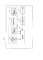
まず、本発明にかかる実施の形態1における非接触ICカードについて説明する。図1は、実施の形態1における非接触ICカード101の機能ブロック図である。また、図2は、上記非接触ICカード101のハードウェア構成図である。上記非接触ICカード101は、アンテナ203、送受信回路202、CPU201、当該非接触ICカードを制御するためのプログラムが格納されているROM(Read Only Memory)204、プログラム実行時に例えばワークエリアとして使用されるRAM(Random Access Memory)205より構成されている。
【0032】
ここで上記非接触ICカード101は、リーダライタ等の通信可能エリアに入ると、上記リーダライタからの電磁波より上記アンテナ203を介して誘導される電力にて動作する。
【0033】
上記非接触ICカード101を機能別に表した場合、図1に示すようにアンテナ手段107、送受信手段106、制御手段105、応答判定手段102、応答タイミング変更手段103、利用決定手段104を備える。ただし、各手段の処理の詳細については適宜説明を行う。
【0034】
尚、例えば上記応答判定手段102、応答タイミング変更手段103、利用決定手段104は、図2に示したROM204にプログラムとして格納され、必要に応じてCPU201に読み出されて実行される。
【0035】
次に、図3、図4を用いて本実施の形態1に係る非接触ICカードの処理について説明する。ここに図3は、非接触ICカード101が実行する処理のフローチャートである。尚、理解に供するため、本実施の形態1では図16のように2つの非接触ICカード1601(非接触ICカード101)、1602が、リーダライタ1600と通信を行うものとする。
【0036】
まず、非接触ICカード101を構成する制御手段105はリーダライタから初期要求リクエストが送信されてくるのを待機する(図3:S300NO)。ここで上記リーダライタからの初期要求リクエストを、アンテナ手段107及び送受信手段106を介して受信した場合、制御手段105は当該初期要求リクエストの中からタイムスロット数を取得する(図3:S300YES→S301)。尚、タイムスロット数は、図18に示されるPARAMのBit1〜Bit3の3bit1803で指定されており、このbitに指定される値の2の乗数がタイムスロット数となる。以下にタイムスロット数の計算式(式2)を示す。
【0037】
タイムスロット数(N)=2 n : 式2
(nはBit1〜Bit3であらわされる0から4までの値)
図4に示すように、通常、タイムスロット401は、所定の時刻402から2266μsec後の時刻403までの時間間隔で構成される。
【0038】
次に、上記制御手段105は、1から式2で示されるタイムスロット数(N)の間の整数を1つ選択することで応答を行うタイムスロットを決定する(図3:S302)。
【0039】
続いて、上記制御手段105は、上記リーダライタに初期応答を送信するタイムスロットの開始時刻まで待機する(図3:S303NO)。利用決定手段104は、上記時刻に到達した時点で応答判定手段102を使用するか否かを例えば所定の確立で決定する(図3:S303YES→S304)。但し、上記応答判定手段102を必ず利用する場合には、上記利用決定手段104は必要ない。
【0040】
ここで、上記応答判定手段102を使用する場合、当該応答判定部102は、例えば以下のように他の非接触ICカードからの初期応答の有無を判定する(図3:S304YES→S305)。
【0041】
ここで、上記応答判定部102を具備しない、もしくは使用しない非接触ICカードは、上記所定の時刻402直後から初期応答であるATQB404を送信する。尚、上記ATQB404は、例えばSOF(Start Of Frame)410、ヘッダ(初期応答ヘッダ)411、PUPI(カード固有ID:Pseudo-Unique PICC Identifier)412、APP Data(アプリケーション固有データ)413、Protocol Inf(プロトコル情報)414、CRC(Cyclic Redundancy Check)415、EOF(End Of Frame)416により構成される。
【0042】
非接触ICカード101は、上記タイムスロット401のタイミング内(所定の時刻402から2266μsec以内)に初期応答(送信時間約1539μsec)を送信すればよいため、ここでは例えば上記所定の時刻402から所定の判定期間416経過後にATQB405を送信する。尚、上記判定期間416は例えば217μsecである。
【0043】
但し、上記ATQB405を送信するまでに、他の非接触ICカード(例えば非接触ICカード1602)の上記SOF410やヘッダ411、又は初期応答の衝突等を受信した場合、上記応答判定手段102は、他の非接触ICカードの初期応答有りと判定する(図3:S305YES→S306)。
【0044】
上記応答判定手段102が、他の非接触ICカードの初期応答有りと判定すると、続いて応答タイミング変更手段103は、上記タイムスロットが変更可能であるかどうかを判定する(図3:S306)。尚、他の非接触ICカードからの初期応答やSOF、ヘッダ等は、上記リーダライタから初期応答リクエストを受信するのと同様の手順で受信可能である。
【0045】
ここで、上記タイムスロットの変更とは、例えば上記リーダライタから複数のタイムスロットを取得した場合であって、上記所定の時刻402が最後のタイムスロットではない場合、当該タイムスロットに続くタイムスロットにて初期応答を行うことを言う。尚、上記「続くタイムスロット」とは、1つ後のタイムスロットでもよいし、複数個後のタイムスロットでもよい。変更可能ではない場合とは、例えばリーダライタから与えられたタイムスロットが1の場合や、現在初期応答に利用しているタイムスロットが、リーダライタから与えられた最後のタイムスロットである最終スロットの場合等である。
【0046】
上記応答タイミング変更手段103がタイムスロットを変更可能であると判断した場合には、さらに応答するタイムスロットの変更を行い、制御手段105は再度応答するタイムスロットか否かの判定を行う(図3:S306YES→S307→S303)。
【0047】
上記応答判定手段102の使用をしない場合(図3:S304NO)、他の非接触ICカードの初期応答がない場合(図3:S305NO)、スロットの変更が不可能である場合(図3:S306NO)には、上記制御手段105は、初期応答を上記リーダライタに対して送信する(図3:S308)。
【0048】
以上のように、他の非接触ICカードの初期応答や初期応答の衝突を判定し、さらに初期応答や初期応答の衝突があった場合には応答に利用するタイムスロットを変更することで、初期応答の衝突を最小限に抑えた非接触ICカードを提供することが可能になる。
【0049】
続いて、上記処理による衝突の軽減について具体的に図を用いて説明する。
【0050】
図5に示すのは、従来の非接触ICカード502、502がリーダライタに初期応答を行う場合の衝突の確率を図示したものである。尚、×は衝突を示し、○は衝突しないことを示す。
【0051】
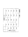
ここで、理解に供するため、リーダライタより与えられるタイムスロット数を2としている。すなわち、非接触ICカード501や、非接触ICカード502は、Slot1とSlot2の2つを選択可能である。
【0052】
まず、非接触ICカード501、502は、それぞれSlot1とSlot2の2つのスロットが選択可能であるので、2×2=4通りの選択状態がある。図5では、各々の状態を矩形で示し、各矩形に(1)から(4)までの番号をつけ、各番号の衝突の有無を以下に示す。
【0053】
(1):非接触ICカード501がSlot1を選択し、非接触ICカード502がSlot1を選択。したがって、衝突が発生する。
【0054】
(2):非接触ICカード501がSlot2を選択し、非接触ICカード502がSlot1を選択。したがって、衝突は発生しない。
【0055】
(3):非接触ICカード501がSlot1を選択し、非接触ICカード502がSlot2を選択。したがって、衝突は発生しない。
【0056】
(4):非接触ICカード501がSlot2を選択し、非接触ICカード502がSlot2を選択。したがって、衝突が発生する。
【0057】
以上から、衝突が発生する確率は、
2/4=50% : 式3
と計算される。
【0058】
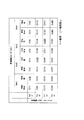
図6は、本発明に係る非接触ICカード601、602を用いた場合で、ここでも、リーダライタから与えられるタイムスロット数を2としている。即ち、非接触ICカード601や、非接触ICカード602は、Slot1とSlot2の2つを選択可能である。
【0059】
また、上記利用決定手段104が他の非接触ICカードの初期応答を判定するか否かの確率を1/2、すなわち、判定する場合と判定しない場合がそれぞれ半分づつと仮定する。
【0060】
この場合、非接触ICカード601と非接触ICカード602は、各タイムスロットで衝突判定をする場合と判定をしない場合の2通りあるので4×4=16通りの状態がある。
【0061】
各々の状態を図6では矩形で示し、各矩形に(1)から(16)までの番号をつけ、各番号の衝突の有無を以下に示す。
【0062】
(1):非接触ICカード601は、Slot1を選択し、なおかつ他の非接触ICカードが初期応答を行っているかを判定している状態で、非接触ICカード602も非接触ICカード601と同様に、Slot1を選択し、なおかつ他の非接触ICカードが初期応答を行っているかを判定している状態である。互いに初期応答を行っていない状態のため、非接触ICカード601、および、非接触ICカード602はSlot1へ初期応答を応答し、衝突が発生する。
【0063】
(2):非接触ICカード601は、Slot1を選択し、なおかつ他の非接触ICカードが初期応答を行っているかを判定せず、Slot1に初期応答を行う状態であり、非接触ICカード602は、Slot1を選択し、なおかつ他の非接触ICカードが初期応答を行っているかを判定している状態である。非接触ICカード602は、非接触ICカード601がSlot1に初期応答を行っていることを認識してSlot2へ初期応答を行い、初期応答の衝突回避を行うため衝突は発生しない。
【0064】
(3):非接触ICカード601がSlot2を選択し、なおかつ他の非接触ICカードが初期応答を行っているかを判定する状態で、非接触ICカード602がSlot1を選択し、なおかつ他の非接触ICカードが初期応答を行っているかを判定する状態である。非接触ICカード601、602は各タイムスロットを監視したが、他の非接触ICカードによる初期応答が行われていないため、各々選択したスロットに初期応答を応答する。したがって、衝突は発生しない。
【0065】
(4):非接触ICカード601は、Slot2を選択し、なおかつ他の非接触ICカードが初期応答を行っているかを判定しないので、Slot2へ送信を行う状態である。また、非接触ICカード602は、Slot1を選択し、なおかつ他の非接触ICカードが初期応答を行っているかを判定している状態である。非接触ICカード602は、Slot1を監視したが、他の非接触ICカードによる初期応答が行われていないため、Slot1へ初期応答を応答し、非接触ICカード601は、スロット2へ送信を行う。したがって、衝突は発生しない。
【0066】
(5):非接触ICカード601は、Slot1を選択し、なおかつ他の非接触ICカードが初期応答を行っているかを判定している状態である。非接触ICカード602は、Slot1を選択し、なおかつ他の非接触ICカードが初期応答を行っているかを判定せず、Slot1に初期応答を行う。この場合、非接触ICカード601は、非接触ICカード602がSlot1に初期応答を行っていることを認識し、Slot2へ初期応答を行うため衝突は発生しない。
【0067】
(6):非接触ICカード601は、Slot1を選択し、なおかつ他の非接触ICカードが初期応答を行っているかを判定しない状態で、非接触ICカード602も非接触ICカード601と同様に、Slot1を選択し、なおかつ他の非接触ICカードが初期応答を行っているかを判定しない状態である。互いにスロット1に対して初期応答を行うため、衝突が発生する。
【0068】
(7):(3)や(4)と同様に異なるタイムスロットを選択しているため衝突は発生しない。
【0069】
(8):(3)や(4)と同様に異なるタイムスロットを選択しているため衝突は発生しない。
【0070】
(9):(3)や(4)と同様に異なるタイムスロットを選択しているため衝突は発生しない。
【0071】
(10):(3)や(4)と同様に異なるタイムスロットを選択しているため衝突は発生しない。
【0072】
(11):非接触ICカード601は、Slot2を選択し、なおかつ他の非接触ICカードが初期応答を行っているかを判定している状態であるが、Slotの変更はできないため、Slot2へ送信を行う状態。非接触ICカード602も同様に、Slot2を選択し、なおかつ他の非接触ICカードが初期応答を行っているかを判定する状態であるが、Slotは変更できないため、Slot2へ送信を行う状態。したがって、衝突が発生する。
(12):(11)と同様にSlot2にしか送信できないため衝突が発生する。
【0073】
(13):(3)や(4)と同様に異なるタイムスロットを選択しているため衝突は発生しない。
【0074】
(14):(3)や(4)と同様に異なるタイムスロットを選択しているため衝突は発生しない。
【0075】
(15):(11)と同様にSlot2にしか送信できないため衝突が発生する。
【0076】
(16):(11)と同様にSlot2にしか送信できないため衝突が発生する。
【0077】
以上から、衝突が発生する確率は、
6/16≒37.5% :式4
と計算される。
【0078】
以上のように、式3及び式4より衝突が発生する確率は、式4が小さくなっている。従って、本発明に係る非接触ICカード同士の環境において、衝突確率が減少する。
【0079】
次に、図7は、本発明に係る非接触ICカード701と従来の非接触ICカード702を用いた場合で、ここでは、リーダライタから与えられるタイムスロット数を2としている。すなわち、非接触ICカード701や、非接触ICカード702は、Slot1とSlot2の2つを選択可能である。
【0080】
また、利用決定手段が他の非接触ICカードの初期応答を判定するか否かの確率を1/2、すなわち、判定する場合と判定しない場合はそれぞれ半分づつと仮定する。
【0081】
この場合、非接触ICカード701は、各タイムスロットで衝突判定をする場合と判定をしない場合の2通りあるので、4×2=8通りの状態がある。
【0082】
上記各々の状態を図7にて矩形で示し、各矩形に(1)から(8)までの番号をつけ、各番号の衝突の有無を以下に示す。
【0083】
(1):非接触ICカード701は、Slot1を選択し、なおかつ他の非接触ICカードが初期応答を行っているかを判定している状態で、非接触ICカード702は、Slot1へ初期応答を行う状態である。非接触ICカード701は、非接触ICカード702の初期応答を認識するため、非接触ICカード701は、Slot2を用いて初期応答を行う。したがって、衝突の回避が行われるため、衝突は発生しない。
【0084】
(2):非接触ICカード701は、Slot1を選択し、なおかつ他の非接触ICカードが初期応答を行っているかを判定しない状態であるため、Slot1へ初期応答を行う状態である。非接触ICカード702は、Slot1へ初期応答を行う状態である。両非接触ICカードはSlot1を用いて初期応答を行うため、衝突が発生する。
【0085】
(3):非接触ICカード701は、Slot2を選択し、なおかつ他の非接触ICカードが初期応答を行っているかを判定している状態であるが、Slot1へは送信できないため、Slot2へ送信を行う状態である。非接触ICカード702は、Slot1へ初期応答を行う状態である。したがって、衝突は発生しない。
【0086】
(4):(3)と同様に異なるタイムスロットに送信するため、衝突は発生しない。
【0087】
(5):(3)と同様に異なるタイムスロットに送信するため、衝突は発生しない。
【0088】
(6):(3)と同様に異なるタイムスロットに送信するため、衝突は発生しない。
【0089】
(7):非接触ICカード701は、Slot2を選択し、なおかつ他の非接触ICカードが初期応答を行っているかを判定する状態であるが、Slot1へは送信できないため、Slot2へ送信を行う状態である。非接触ICカード702は、Slot2へ初期応答を行う状態である。したがって、衝突が発生する。
【0090】
(8):非接触ICカード701は、Slot2を選択し、なおかつ他の非接触ICカードが初期応答を行っているかを判定しない状態であるため、Slot2へ送信を行う状態である。非接触ICカード702は、Slot2へ初期応答を行う状態である。したがって、衝突が発生する。
【0091】
以上から、衝突が発生する確率は、
3/8≒37.5% :式5
と計算される。
【0092】
上記式3及び式5より衝突が発生する確率は、式5が小さくなる。したがって、本発明に係る非接触ICカードと従来の非接触ICカードが混在する環境においても、衝突確率が減少することがわかる。
【0093】
尚、例えば本発明に係る非接触ICカード701が利用決定手段104を備えない場合、即ちすべての場合に対して他の非接触ICカードの初期応答の有無を判定する場合を考える。この場合、図7に示すように、本発明に係る非接触ICカードと従来の非接触ICカードが混在する環境において衝突が発生する確率は、
1/4=25% と計算される。
【0094】
即ち、本発明に係る非接触ICカードと従来の非接触ICカードが混在する環境においては、上記利用決定手段104が無い、又は機能しない場合(図7の★マークに該当)の方が衝突の発生を減らすことが可能である。
【0095】
続いて、上記ではリーダライタから与えらえるタイムスロット数を2としたが、更にタイムスロット数が4の場合を以下に検証する。
【0096】
図8、図9、図10は、それぞれ、図5、図6、図7で説明を行ったタイムスロット数を2から4に変更した場合の図であり、他の条件は同一である。
【0097】
図8より、従来例の非接触ICカード801、802を用いて、スロット数を4にした場合の衝突確立は、
4/16=25% :式6
と計算される。
【0098】
図9より、本発明に係る非接触ICカード901、902を用いた場合において、タイムスロット数を4とした場合の衝突確率は、
10/64≒15.6% :式7
と計算される。
【0099】
上記式6及び式7より衝突が発生する確率は、式7が小さくなる。したがって、本発明に係る非接触ICカード同士の環境において衝突確率が減少する。
【0100】
図10より、本発明に係る非接触ICカード1001と従来例の非接触ICカード1002を用いて、タイムスロット数を4とした場合の衝突確率は、
5/32≒15.6% :式8
と計算される。
【0101】
上記式6及び式8より衝突が発生する確率は、式8が小さくなる。したがって、本発明に係る非接触ICカードと従来の非接触ICカードの環境においても、衝突確率が減少する。
【0102】
尚、例えば本発明に係る非接触ICカード1001が利用決定手段104を備えない場合、即ちすべての場合に対して他の非接触ICカードの初期応答の有無を判定する場合を考える。この場合、図10に示すように、本発明に係る非接触ICカードと従来の非接触ICカードが混在する環境において衝突が発生する確率は、
1/16≒6.3% と計算される。
【0103】
即ち、本発明に係る非接触ICカードと従来の非接触ICカードが混在する環境においては、上記利用決定手段104が無い、又は機能しない場合(図10の★マークに該当)の方が衝突の発生を減らすことが可能である。
【0104】
以上のように、他の非接触ICカードによる応答の有無を判定し、当該判定の結果に応じて応答のタイムスロットを変更することで非接触ICカードが初期応答を行う際の初期応答の衝突を低減することができる。また、上記応答の有無の判定の実行を所定の確率で決定することにより、本発明に係る非接触ICカード同士の初期応答時にも、応答の衝突を軽減することが可能となる。
【0105】
尚、他の非接触ICカードによる応答の有無を判定しない場合には、最終のタイムスロットを乱数で選択した場合であっても当該タイムスロットを変更しないようにしてもよい。
【0106】
他の非接触ICカードによる応答の有無を判定しない場合には、タイムスロットを変更することがないため、結果として選択可能なタイムスロットの数の減少を防止することができる。
【0107】
(実施の形態2)
図11は、実施の形態2に係る非接触ICカード1100の機能ブロック図であり、図12は、非接触ICカード1100が実行する処理のフローチャートである。
【0108】
尚、本実施の形態2における非接触ICカードは、上記実施の形態1における非接触ICカードとほぼ同様の構成を有するため、異なる点のみ説明を行う。
【0109】
上記実施の形態1に係る非接触ICカード101では、初期応答スロットとして、最終スロットを選択した場合には、最終スロットで初期応答や当該初期応答の衝突を検知できても、タイムスロットの変更ができないため必ず衝突が発生してしまうという問題がある。この問題を解決するために実施の形態2に示す技術を適用する。尚、ここで言う最終スロットとは、リーダライタより与えられた複数個のタイムスロットのうち、応答可能な最後のタイムスロットを指し、例えば図10におけるSlot4がこれに該当する。
【0110】
まず、非接触ICカード1100はリーダライタから初期要求リクエストが送信されてくるのを待機し、初期応答リクエストを受信すると応答すべきタイムスロットを選択するのは上記実施の形態1と同様である(図11:S300〜S302)。
【0111】
ここで、実施の形態2では、上記非接触ICカード1100を構成する最終スロット判定手段1101は、まず上記リーダライタから与えられたタイムスロット数が“1”であるか否かを判定する(図12:S1201)。
【0112】
ここでリーダライタから与えられたタイムスロット数が“1”で無い場合、さらに上記選択した応答すべきタイムスロットが最終スロットであるか否かを判定する(図12:S1201NO→S1202)。
【0113】
ここで、上記選択した応答すべきタイムスロットが最終スロットである場合、再度応答すべきタイムスロットの選択よりやり直す(図12:S1202YES→S302)。
【0114】
尚、リーダライタから与えられるスロット数が1の場合(図12:S1201YES)や、応答すべきタイムスロットが最終スロットではない場合(図12:S1201NO)には、応答するタイムスロット(タイミング)が来るまで待機し、以後実施の形態1と同様に初期応答の送信までの処理を行う(図12:S303→S308)。
【0115】
以上のように、最終スロット判定手段を設けることで、必要であれば必ずタイムスロットの変更を行うことが可能となり、衝突の回避を行う場合が増加し、衝突の減少を図ることが可能となる。
【0116】
尚、上記最終スロット判定手段は、図12に示した処理1200にて最終スロットの選択を回避しているが、例えばリーダライタから与えられたスロット数から1を引いた値で示されるタイムスロットより、応答するタイムスロットを選択するといった処理でもよい。
【0117】
(実施の形態3)
次に、実施の形態3に係る非接触ICカードについて説明する。本実施の形態3における非接触ICカード1301は、図13に示すように、制御手段105、送受信手段106、アンテナ手段107に加えて測定手段1302、応答タイミング決定手段1303を備える。ここで、上記制御手段105、送受信手段106、アンテナ手段107については、上記実施の形態1、2にて説明したのと同様であり、上記測定手段1302、応答タイミング決定手段1303の処理については適宜説明する。尚、非接触ICカードにおける起電力と磁界強度の関係を示したのが図14である。
【0118】
まず、図14について説明を行う。非接触ICカードは、リーダライタが発する電磁波により構成される磁界内に進入することにより、起電力を得る事が出来る。上記磁界内で得られる起電力は、磁界強度により異なるのは知られているがさらに、非接触ICカードの枚数によっても起電力は異なるのである。つまり、非接触ICカードを複数所有する場合、当該非接触ICカードを財布内等に重ねて入れるのが通常である。このような場合には、上記財布に非接触ICカードを入れたまま例えば上記磁界内に進入すると、リーダライタに近い非接触ICカード(内側)はグラフ1402に示すように、リーダライタから遠い非接触ICカード(外側)のグラフ1403よりも起電力(電圧)が高くなる。これは、上記非接触ICカード(内側)にて電磁波がある程度吸収されるためであると予想される。これは非接触ICカードを2枚重ねている場合の起電力であるが、非接触ICカードが1枚の場合には、上記非接触ICカード(内側)よりもより高い起電力を得られることがグラフ1401より読み取れる。
【0119】
本実施の形態3では、この特性を利用してタイムスロットを決定しようとするものである。
【0120】
まず、非接触ICカード1301が磁界内に進入し、起電力が発生した場合、測定手段1302は適宜、当該起電力を測定し、起電力の値を上記応答タイミング決定手段1303に送信する。
【0121】
上記測定結果を受信した上記応答タイミング決定手段1303は、所定のタイミング1404(電圧が所定の値になった際)にて、当該電圧の微分値を算出する。これにより、上記所定のタイミング1404における電圧とその微分値を得る事ができる。
【0122】
次に、上記応答タイミング決定手段1303は、上記タイミング1404において実際に得られた電圧の微分値と、予め保持している起電力と磁界強度との関係から得られる電圧の微分値とを比較する。尚、予め保持している起電力と磁界強度との関係を示す情報は、図14に示すグラフで表現可能である。上記タイミング1404における各非接触ICカードの電圧の微分値は、上記グラフ1401、1402、1403におけるポイント1405、1406、1407の傾きを意味する。
【0123】
上記比較により、上記応答タイミング決定手段1303が算出した微分値は、上記ポイント1405、1406、1407の何れかの傾きと一致、又は近い値を示すため、非接触ICカード1301が置かれている状況をある程度判断できる事になる。つまり、例えば上記比較により、タイミング1404に対応する微分値がポイント1406の値と一致する場合、該当する非接触ICカード1301が2枚のカードの内側であると判断することが可能となる。
【0124】
続いて、該当する非接触ICカード1301が置かれている状況を判断した後、応答タイミング決定手段1303は、初期応答リクエストにて与えられたタイムスロットから、応答に用いるタイムスロットを決定するのである。
【0125】
上記タイムスロットの決定方法はどのようであってもよいが、例えば以下のような決定が行われる。
【0126】
即ち、非接触ICカードが1枚と判断された場合(グラフ1401)、上記応答タイミング決定手段1303は、通常通りランダムにタイムスロットを選択し或いは1番目のタイムスロットを選択する。
【0127】
非接触ICカードが2枚と判断された場合でさらに内側と判断された場合(グラフ1402)、上記応答タイミング決定手段1303は例えば1番目のタイムスロットを選択する。この場合、2枚と判断された場合でさらに外側と判断された非接触ICカード(グラフ1403)の上記応答タイミング決定手段1303は、2番目のタイムスロットを選択するのである。
【0128】
以上のように、起電力変化時の微分値、起電力の測定値、及び上記起電力と上記磁界強度との関係を示す情報に基づいて非接触ICカードの状況を判断し、当該判断に応じて応答タイミング(タイムスロット)を決定することで、非接触ICカードの初期応答の衝突を減少させる事が可能になる。
【0129】
ところで、上述したのは、応答タイミング決定手段1303が微分値を算出する方法であったが、以下のようにして非接触ICカードの状況を判断してもよい。
【0130】
即ち、リーダライタが上記非接触ICカードと通信する距離が予め決められているシステムがある。例えば複数枚の非接触ICカードをリーダーに指し込み、リード位置に固定した後に当該非接触ICカードと通信するシステム等が該当する。
【0131】
このようなシステムでは、非接触ICカードが通信を行う際の磁界強度は一定値となるはずである。上記リード位置の磁界強度が例えば図15に示すポイント1501であるとすると、上記非接触ICカードが初期応答リクエストを受信した際の電圧は、当該非接触ICカードの状況に応じて例えばA1502(V)、B1503(V)、C1504(V)となるはずである。尚、上記A1502は
非接触ICカードが1枚の場合、B1503は非接触ICカードが2枚の内側の場合、C1504は非接触ICカードが2枚の外側の場合である。
【0132】
つまり、初期応答リクエストを受信した際に上記測定手段1302が測定した起電力の測定値と、上記起電力と上記磁界強度との関係を示す情報(図15)とに基づいて、上記応答タイミング決定手段1303は、上記非接触ICカードの状況を判断可能である。
【0133】
以後、応答タイミング決定手段1303は、初期応答リクエストにて与えられたタイムスロットから、応答に用いるタイムスロットを決定するのは上述した通りである。
【0134】
以上のように、磁界強度が固定の場合には、起電力の測定値、及び上記起電力と上記磁界強度との関係を示す情報に基づいて非接触ICカードの状況を判断し、当該判断に応じて応答タイミング(タイムスロット)を決定することで、非接触ICカードの初期応答の衝突を減少させる事が可能になる。
【0135】
また更に、以下のようにして非接触ICカードの状況を判断してもよい。
【0136】
リーダライタが発生する磁界強度の規格は、例えば一般的な実装規約では磁界強度にある程度幅を持たせて定義されている。このような場合には、リーダライタによってリード位置における磁界強度が異なるため、上記方法が利用できない事になる。このような場合には、リーダライタが送信する初期応答リクエストに、当該リーダライタが発生している磁界強度の情報を含めて送信するとよい。
【0137】
上記磁界強度の情報を含む初期応答リクエストを受信すると、上記非接触ICカード1301を構成する磁界強度取得手段1304は、当該初期応答リクエストより磁界強度の情報を取得し、上記応答タイミング決定手段1303に送信する。例えば上記磁界強度の情報が例えばポイント1505にて示される値であった場合、A‘1506(V)、B’1507(V)、C‘1508(V)が起電力と磁界強度との関係を示す情報から得られる値である。当該値と、測定手段1302が測定した起電力とを比較する事により、上記応答タイミング決定手段1303は、上記非接触ICカードの状況を判断可能である。
【0138】
以後、応答タイミング決定手段1303は、初期応答リクエストにて与えられたタイムスロットから、応答に用いるタイムスロットを決定するのは上述した通りである。
【0139】
以上のように、本発明に係る非接触ICカードは、磁界強度が固定ではない場合であっても、磁界強度取得手段が初期応答リクエストに含まれる磁界強度に関する情報を取得する事で、起電力の測定値、及び上記起電力と上記磁界強度との関係を示す情報に基づいて非接触ICカードの状況を判断することが可能となり、非接触ICカードの初期応答の衝突を減少させる事が可能になる。
【0140】
尚、本実施の形態における図14、図15には、非接触ICカードが1枚の場合と2枚の場合についてのグラフのみ示したが、非接触ICカードが3枚以上の場合においても、それぞれ独立したグラフを得る事が可能である。従って同様の処理にて非接触ICカードの状況を判断可能である事はいうまでもない。
【発明の効果】
【0141】
以上のように、他の非接触ICカードの初期応答や初期応答の衝突を判定し、さらに初期応答や初期応答の衝突があった場合には応答に利用するタイムスロットを変更することで、初期応答の衝突を最小限に抑えることが可能となる。
【0142】
また、応答の有無の判定の実行を所定の確率で決定することにより、本発明に係る非接触ICカード同士の初期応答時にも、応答の衝突を軽減することが可能となる。
【0143】
さらに、最終スロット判定手段を設けることで、可能であれば必ずタイムスロットの変更を行うことが可能となり、衝突の回避を行う場合が増加し、衝突の減少を図ることが可能となる。
また、起電力変化時の微分値、起電力の測定値、及び上記起電力と上記磁界強度との関係を示す情報に基づいて非接触ICカードの状況を判断し、当該判断に応じて応答タイミング(タイムスロット)を決定することで、非接触ICカードの初期応答の衝突を減少させる事が可能になる。
さらに、磁界強度が固定の場合には、起電力の測定値、及び上記起電力と上記磁界強度との関係を示す情報に基づいて非接触ICカードの状況を判断し、当該判断に応じて応答タイミングを決定することで、非接触ICカードの初期応答の衝突を減少させる事が可能になる。
また、磁界強度が固定ではない場合であっても、磁界強度取得手段が初期応答リクエストに含まれる磁界強度に関する情報を取得する事で、起電力の測定値、及び上記起電力と上記磁界強度との関係を示す情報に基づいて非接触ICカードの状況を判断することが可能となり、非接触ICカードの初期応答の衝突を減少させる事が可能になる。
【図面の簡単な説明】
【0144】
【図1】 実施の形態1における非接触ICカードの機能ブロック図
【図2】 実施の形態1における非接触ICカードのハードウェア構成図
【図3】 実施の形態1における非接触ICカードが実行する処理のフローチャート
【図4】 タイムスロット及び初期応答のフォーマットを示す図
【図5】 従来の非接触ICカード同士が初期応答を行う場合の衝突の確率を示す第1図
【図6】 本発明に係る非接触ICカード同士が初期応答を行う場合の衝突の確率を示す第1図
【図7】 従来の非接触ICカード及び本発明に係る非接触ICカードが初期応答を行う場合の衝突の確率を示す第1図
【図8】 従来の非接触ICカード同士が初期応答を行う場合の衝突の確率を示す第2図
【図9】 本発明に係る非接触ICカード同士が初期応答を行う場合の衝突の確率を示す第2図
【図10】 従来の非接触ICカード及び本発明に係る非接触ICカードが初期応答を行う場合の衝突の確率を示す第2図
【図11】 実施の形態2における非接触ICカードの機能ブロック図
【図12】 実施の形態2における非接触ICカードが実行する処理のフローチャート
【図13】 実施の形態3における非接触ICカードの機能ブロック図
【図14】 非接触ICカードにおける起電力と磁界強度の関係を示す第1の図
【図15】 非接触ICカードにおける起電力と磁界強度の関係を示す第2の図
【図16】 リーダライタ及び非接触ICカードの通信状態を示すイメージ図
【図17】 タイムスロット方式を示すイメージ図
【図18】 初期応答リクエストパケットのフォーマットを示す図
【符号の説明】
【0145】
101 非接触ICカード
102 応答判定手段
103 応答タイミング変更手段
104 利用決定手段
105 制御手段
106 送受信手段
107 アンテナ手段[0001]
BACKGROUND OF THE INVENTION
[0002]
The present invention relates to a contactless IC card, a response method, and a program thereof, and more particularly, to a contactless IC card that responds to a request transmitted from a reader / writer using a time slot, a response method, and a program thereof.
[Prior art]
[0003]
Conventionally, a time slot method has been adopted for communication between a non-contact IC card that exchanges data using an electromagnetic induction method or the like and a reader / writer that recognizes the non-contact IC card. This is because when a plurality of non-contact IC cards are simultaneously present in the communicable area of the reader / writer and a plurality of non-contact IC cards respond simultaneously to polling from the reader / writer, each response signal used for the response This is because no contactless IC card can normally communicate with the reader / writer due to the collision.
[0004]
The time slot communication method will be described below.
[0005]
(1) First, the reader / writer transmits an initial response request command as a request to the non-contact IC card in order to confirm the presence of the non-contact IC card. The initial response request command includes a “slot number” or a value necessary for calculating the “slot number” necessary for controlling the timing of the initial response performed by the non-contact IC card.
[0006]
(2) After receiving the initial response request command, the non-contact IC card returns the initial response to a time slot (1 to “slot number”) provided from a specific time. The time slot used for the response, that is, the timing, is determined by the non-contact IC card itself with a random number.
[0007]
(3) When the reader / writer detects a collision of initial responses that occurs when a plurality of contactless IC cards select the same time slot, the reader / writer transmits the initial response request again.
[0008]
(4) The reader / writer recognizes all non-contact IC cards by receiving initial responses from all non-contact IC cards without collision, and completes the sequence for identifying the cards.
[0009]
The above processing will be described in more detail with reference to FIGS. The following is the processing of the non-contact IC card in the case of conforming to the international standard ISO / IEC14443 of the proximity type non-contact IC card.
[0010]
ISO / IEC14443 can be applied to, for example, a non-contact telephone card. More specifically, as shown in FIG. 16, it is assumed that
[0011]
In the ISO / IEC14443 contactless IC card recognition system, the contactless IC card is recognized by the following procedure.
[0012]
First, the reader /
[0013]
The non-contact IC card responds with N slots from 1 to N. In this explanation, the number of time slots (N) is assumed to be 4. That is, the
[0014]
In the first
[0015]
In the
[0016]
Timing (μsec) = 302 μsec + 2266 μsec × (selected slot number−1): (formula 1)
As such a system, a wireless identification device (Japanese Patent Laid-Open No. 9-6934) is also disclosed, and there is a slot marker method similar to the time slot method.
[0017]
The slot marker method is a method in which after the reader / writer transmits an initial response request in the time slot method, the reader / writer further transmits a slot marker command indicating the start of the slot at each slot start timing. Therefore, this is essentially the same as the time slot method in that each IC card recognizes each IC card by responding using the time slot designated by the reader / writer.
[Patent Document 1]
Japanese Patent Laid-Open No. 9-6934
[Patent Document 2]
JP-A-11-205334
[Problems to be solved by the invention]
[0018]
In the wireless identification device described in the above Japanese Patent Laid-Open No. 9-6934 and the above-mentioned non-contact IC card conforming to the international standard ISO / IEC14443, when the non-contact IC card makes a response to the reader / writer, The contact IC card itself selects a time slot using a random number, and responds within a time interval specified by the time slot. For this reason, for example, when the random numbers generated by a plurality of contactless IC cards are the same, the selected time slots are the same, and the initial responses always collide. In this case, the reader / writer needs to transmit the initial response request command again to perform recognition processing of the non-contact IC card, and as a result, recognition of the non-contact IC card is delayed.
[0019]
It is also possible to reduce the probability that the non-contact IC card selects the same time slot by increasing the number of time slots designated by the reader / writer for the non-contact IC card. However, by increasing the time slot, the time until all the time slots are completed (finished) increases, and as a result, it takes time for the reader / writer to recognize the non-contact IC card.
[0020]
The problem that takes time to recognize as described above is particularly noticeable in a system in which a user needs to make a reader / writer recognize a non-contact IC card without stopping, such as a ticket gate of a train. That is, when the recognition of the non-contact IC card is delayed, the user needs to stop, and as a result, the use of the system is hindered.
[0021]
In addition, if recognition of the non-contact IC card is performed at high speed, it can be applied to a higher-speed moving body, so that further increase in recognition and processing speed in the field of use of the non-contact IC card is desired. It is rare.
[0022]
An object of the present invention is to provide a non-contact IC card, a response method, and a program therefor, in which the initial response collision is minimized.
[Means for Solving the Problems]
[0023]
The present invention employs the following means in order to achieve the above object. That is, the present invention provides a request transmitted from the reader / writer by the reader / writer.MultipleTime slotsTime slot selected fromIt assumes a non-contact IC card that responds using Here, the response determination means isWhile the pre-determined judgment period has elapsed from the start time of the selected time slot,Other contactless IC cardsBased on whether or not a response was received fromDetermine if there is a response. Subsequently, the response timing changing meansWhen it is determined that there is a response from another non-contact IC card and there is a time slot following the selected time slot, the time slot used for the response is set to the time slot after the selected time slot.change.
[0024]
Therefore, the initial response or initial response collision of another non-contact IC card is determined, and if there is an initial response or initial response collision, the time slot used for the response is changed, so that the initial response conflict Can be minimized.
[0025]
further,At the start of the selected time slot,Use determination means for determining the use of response determination meansThe
[0026]
In this configuration, it is possible to reduce the collision of responses even during the initial response between the non-contact IC cards according to the present invention by determining the execution of the presence / absence of the response with a predetermined probability.
[0027]
And alsoThe selected time slot isA final slot determining means for determining whether or not it is the last slot among a plurality of time slots given from the reader / writer, and the response timing changing means is the final slot determining meansIf it is determined that is the last slot, by selecting again one of a plurality of time slots given by the reader / writer,There is a configuration in which the time slot used for response is changed.
[0028]
In this configuration, the time slot can be changed whenever possible, the number of cases where collision is avoided increases, and collision can be reduced.
[0029]
The non-contact IC card can be embodied using a computer. in this case,Response determination means, response timing change means, usage determination means, and final slot determination meansIt is embodied by running a program on a computer.
DETAILED DESCRIPTION OF THE INVENTION
[0030]
Hereinafter, embodiments of the present invention will be described with reference to the accompanying drawings for understanding of the present invention. In addition, the following embodiment is an example which actualized this invention, Comprising: It is not the thing of the character which limits the technical scope of this invention.
[0031]
(Embodiment 1)
First, the non-contact IC card according to the first embodiment of the present invention will be described. FIG. 1 is a functional block diagram of
[0032]
Here, when the
[0033]
When the
[0034]
For example, the
[0035]
Next, processing of the non-contact IC card according to the first embodiment will be described with reference to FIGS. FIG. 3 is a flowchart of processing executed by the
[0036]
First, the control means 105 constituting the
[0037]
Number of time slots (N) = 2 n :
(N is a value from 0 to 4 represented by Bit1 to Bit3)
As shown in FIG. 4, the time slot 401 is usually composed of a time interval from a
[0038]
Next, the control means 105 determines a time slot in which a response is made by selecting one integer between 1 and the number of time slots (N) expressed by Equation 2 (FIG. 3: S302).
[0039]
Subsequently, the control means 105 waits until the start time of the time slot for transmitting the initial response to the reader / writer (FIG. 3: S303 NO). The usage determining means 104 determines whether or not to use the response determining means 102 when the time is reached, for example, by a predetermined establishment (FIG. 3: S303 YES → S304). However, when the
[0040]
Here, when the
[0041]
Here, a non-contact IC card that does not include or does not use the
[0042]
The
[0043]
However, if the
[0044]
When the
[0045]
Here, the change of the time slot is, for example, when a plurality of time slots are acquired from the reader / writer, and when the
[0046]
When the response timing changing means 103 determines that the time slot can be changed, the response time slot is further changed, and the control means 105 determines whether or not the time slot is a response time again (FIG. 3). : S306 YES-> S307-> S303).
[0047]
When the response determination means 102 is not used (FIG. 3: S304 NO), when there is no initial response from another non-contact IC card (FIG. 3: S305 NO), when the slot cannot be changed (FIG. 3: S306 NO) ), The control means 105 transmits an initial response to the reader / writer (FIG. 3: S308).
[0048]
As described above, the initial response or initial response collision of another non-contact IC card is determined, and if there is an initial response or initial response collision, the time slot used for the response is changed to change the initial response. It is possible to provide a contactless IC card that minimizes response collisions.
[0049]
Next, collision reduction by the above process will be specifically described with reference to the drawings.
[0050]
FIG. 5 illustrates the probability of collision when the conventional non-contact IC cards 502 and 502 make an initial response to the reader / writer. In addition, * shows a collision and (circle) shows no collision.
[0051]
Here, for the sake of understanding, the number of time slots given from the reader / writer is set to two. That is, for the non-contact IC card 501 and the non-contact IC card 502, two of
[0052]
First, since the non-contact IC cards 501 and 502 can select two slots,
[0053]
(1): Non-contact IC card 501 selects
[0054]
(2): Non-contact IC card 501 selects Slot2, and non-contact IC card 502 selects Slot1. Therefore, no collision occurs.
[0055]
(3): Non-contact IC card 501 selects
[0056]
(4): Non-contact IC card 501 selects
[0057]
From the above, the probability that a collision will occur is
2/4 = 50%:
Is calculated.
[0058]
FIG. 6 shows the case where the non-contact IC cards 601 and 602 according to the present invention are used, and here, the number of time slots given from the reader / writer is also two. That is, the non-contact IC card 601 and the non-contact IC card 602 can select two of
[0059]
In addition, it is assumed that the probability that the
[0060]
In this case, the non-contact IC card 601 and the non-contact IC card 602 have 4 × 4 = 16 states because there are two types of cases where the collision determination is performed in each time slot and the case where the determination is not performed.
[0061]
Each state is indicated by a rectangle in FIG. 6, and each rectangle is numbered from (1) to (16), and the presence or absence of a collision of each number is shown below.
[0062]
(1): The non-contact IC card 601 selects
[0063]
(2): The non-contact IC card 601 is in a state in which the
[0064]
(3): In a state in which the non-contact IC card 601 selects
[0065]
(4): The non-contact IC card 601 is in a state of transmitting to Slot 2 because it selects
[0066]
(5): The non-contact IC card 601 is in a state of selecting
[0067]
(6): The non-contact IC card 601 selects
[0068]
(7): Since different time slots are selected as in (3) and (4), no collision occurs.
[0069]
(8): Since different time slots are selected as in (3) and (4), no collision occurs.
[0070]
(9): Since different time slots are selected as in (3) and (4), no collision occurs.
[0071]
(10): Since a different time slot is selected as in (3) and (4), no collision occurs.
[0072]
(11): The non-contact IC card 601 is in a state in which
(12): Similar to (11), a collision occurs because transmission is possible only to Slot2.
[0073]
(13): Since different time slots are selected as in (3) and (4), no collision occurs.
[0074]
(14): Since different time slots are selected as in (3) and (4), no collision occurs.
[0075]
(15): Similar to (11), a collision occurs because transmission is possible only to Slot2.
[0076]
(16): Similar to (11), a collision occurs because transmission is possible only to Slot2.
[0077]
From the above, the probability that a collision will occur is
6 / 16≈37.5%:
Is calculated.
[0078]
As described above, the probability of a collision occurring from
[0079]
Next, FIG. 7 shows a case where the
[0080]
Further, it is assumed that the probability of whether the usage determining means determines the initial response of another non-contact IC card is ½, that is, when the determination is made and when not determined, the probability is halved.
[0081]
In this case, there are two types of
[0082]
Each of the above states is indicated by a rectangle in FIG. 7, and each rectangle is numbered from (1) to (8), and the presence or absence of a collision of each number is shown below.
[0083]
(1): The
[0084]
(2): The
[0085]
(3): The
[0086]
(4): Since transmission is performed in different time slots as in (3), no collision occurs.
[0087]
(5): Since transmission is performed in different time slots as in (3), no collision occurs.
[0088]
(6): Since transmission is performed in different time slots as in (3), no collision occurs.
[0089]
(7): The
[0090]
(8): The
[0091]
From the above, the probability that a collision will occur is
3 / 8≈37.5%:
Is calculated.
[0092]
From the
[0093]
For example, let us consider a case where the
Calculated as 1/4 = 25%.
[0094]
In other words, in the environment where the non-contact IC card according to the present invention and the conventional non-contact IC card are mixed, the case where the
[0095]
Subsequently, in the above description, the number of time slots given from the reader / writer is 2. However, the case where the number of time slots is 4 will be verified below.
[0096]
FIGS. 8, 9, and 10 are diagrams when the number of time slots described in FIGS. 5, 6, and 7 is changed from 2 to 4, and the other conditions are the same.
[0097]
From FIG. 8, using the non-contact IC cards 801 and 802 of the conventional example, the collision establishment when the number of slots is 4 is
4/16 = 25%:
Is calculated.
[0098]
From FIG. 9, in the case of using the non-contact IC cards 901 and 902 according to the present invention, the collision probability when the number of time slots is 4,
10 / 64≈15.6%:
Is calculated.
[0099]
From the
[0100]
From FIG. 10, using the
5 / 32≈15.6%:
Is calculated.
[0101]
From the
[0102]
For example, let us consider a case where the
It is calculated that 1 / 16≈6.3%.
[0103]
That is, in the environment where the non-contact IC card according to the present invention and the conventional non-contact IC card are mixed, the case where the
[0104]
As described above, it is determined whether or not there is a response from another non-contact IC card, and an initial response collision occurs when the non-contact IC card makes an initial response by changing the response time slot according to the determination result. Can be reduced. Further, by determining the execution of the presence / absence of the response with a predetermined probability, it is possible to reduce the collision of responses even during the initial response between the non-contact IC cards according to the present invention.
[0105]
If it is not determined whether or not there is a response by another non-contact IC card, the time slot may not be changed even when the last time slot is selected with a random number.
[0106]
When it is not determined whether or not there is a response from another non-contact IC card, the time slot is not changed, and as a result, it is possible to prevent a decrease in the number of selectable time slots.
[0107]
(Embodiment 2)
FIG. 11 is a functional block diagram of the
[0108]
Note that the non-contact IC card in the second embodiment has substantially the same configuration as the non-contact IC card in the first embodiment, and therefore only the differences will be described.
[0109]
In the
[0110]
First, the
[0111]
Here, in the second embodiment, the last
[0112]
If the number of time slots given by the reader / writer is not “1”, it is further determined whether or not the selected time slot to be responded is the last slot (FIG. 12: S1201 NO → S1202).
[0113]
Here, if the selected time slot to be responded is the last slot, the process is repeated from the selection of the time slot to be responded again (FIG. 12: S1202 YES → S302).
[0114]
When the number of slots given from the reader / writer is 1 (FIG. 12: S1201 YES) or when the time slot to be responded is not the last slot (FIG. 12: S1201 NO), the time slot (timing) to respond to comes. After that, the processing up to the transmission of the initial response is performed in the same manner as in the first embodiment (FIG. 12: S303 → S308).
[0115]
As described above, by providing the final slot determination means, it is possible to change the time slot whenever necessary, and the number of cases where collision is avoided increases, and collision can be reduced. .
[0116]
The last slot determination means avoids the selection of the last slot in the
[0117]
(Embodiment 3)
Next, a non-contact IC card according to
[0118]
First, FIG. 14 will be described. A non-contact IC card can obtain an electromotive force by entering a magnetic field constituted by an electromagnetic wave generated by a reader / writer. Although it is known that the electromotive force obtained in the magnetic field varies depending on the magnetic field strength, the electromotive force also varies depending on the number of non-contact IC cards. That is, when a plurality of non-contact IC cards are owned, the non-contact IC cards are usually put in a wallet or the like. In such a case, when the contactless IC card is inserted into the wallet, for example, when entering the magnetic field, the contactless IC card (inside) close to the reader / writer is not distant from the reader / writer as shown in the
[0119]
In the third embodiment, this characteristic is used to determine a time slot.
[0120]
First, when the
[0121]
The response
[0122]
Next, the response
[0123]
A situation in which the
[0124]
Subsequently, after determining the situation where the corresponding
[0125]
The time slot may be determined by any method. For example, the following determination is made.
[0126]
That is, when it is determined that there is one non-contact IC card (graph 1401), the response
[0127]
When it is determined that there are two non-contact IC cards and the inner side is further determined (graph 1402), the response
[0128]
As described above, the state of the non-contact IC card is determined based on the differential value when the electromotive force changes, the measured value of the electromotive force, and the information indicating the relationship between the electromotive force and the magnetic field strength, and the determination is made according to the determination. By determining the response timing (time slot), it is possible to reduce the collision of the initial response of the non-contact IC card.
[0129]
By the way, the above is the method in which the response timing determination means 1303 calculates the differential value, but the situation of the non-contact IC card may be determined as follows.
[0130]
That is, there is a system in which the distance over which the reader / writer communicates with the non-contact IC card is determined in advance. For example, a system in which a plurality of non-contact IC cards are inserted into a reader and fixed at the lead position and then communicated with the non-contact IC card is applicable.
[0131]
In such a system, the magnetic field strength when the non-contact IC card performs communication should be a constant value. If the magnetic field intensity at the lead position is, for example, a
When there is one non-contact IC card, B1503 is when two non-contact IC cards are inside, and C1504 is when two non-contact IC cards are outside.
[0132]
That is, the response timing determination is performed based on the measured value of the electromotive force measured by the
[0133]
Thereafter, the response
[0134]
As described above, when the magnetic field strength is fixed, the situation of the non-contact IC card is determined based on the measured value of the electromotive force and the information indicating the relationship between the electromotive force and the magnetic field strength. By determining the response timing (time slot) accordingly, it is possible to reduce the collision of the initial response of the non-contact IC card.
[0135]
Furthermore, the status of the non-contact IC card may be determined as follows.
[0136]
The standard of the magnetic field intensity generated by the reader / writer is defined, for example, by giving a certain range to the magnetic field intensity in a general mounting rule. In such a case, since the magnetic field strength at the lead position differs depending on the reader / writer, the above method cannot be used. In such a case, the initial response request transmitted by the reader / writer may be transmitted including information on the magnetic field strength generated by the reader / writer.
[0137]
When the initial response request including the magnetic field strength information is received, the magnetic field strength acquisition means 1304 constituting the
[0138]
Thereafter, the response
[0139]
As described above, in the non-contact IC card according to the present invention, even when the magnetic field strength is not fixed, the magnetic field strength acquisition unit acquires information on the magnetic field strength included in the initial response request, so that the electromotive force It is possible to judge the status of the non-contact IC card based on the measured value and the information indicating the relationship between the electromotive force and the magnetic field intensity, and it is possible to reduce the collision of the initial response of the non-contact IC card become.
[0140]
In FIGS. 14 and 15 in the present embodiment, only the graphs for the case of one non-contact IC card and the case of two non-contact IC cards are shown, but even in the case of three or more non-contact IC cards, It is possible to obtain independent graphs. Therefore, it goes without saying that the status of the non-contact IC card can be determined by the same processing.
【The invention's effect】
[0141]
As described above, the initial response or initial response collision of another non-contact IC card is determined, and if there is an initial response or initial response collision, the time slot used for the response is changed to change the initial response. Response collisions can be minimized.
[0142]
Also, by determining whether or not there is a response with a predetermined probability, it is possible to reduce response collisions even during an initial response between non-contact IC cards according to the present invention.
[0143]
Furthermore, by providing the final slot determination means, it is possible to change the time slot whenever possible, and the number of cases where collision is avoided increases, and collision can be reduced.
Further, the status of the non-contact IC card is determined based on the differential value when the electromotive force is changed, the measured value of the electromotive force, and information indicating the relationship between the electromotive force and the magnetic field strength, and the response timing is determined according to the determination. By determining (time slot), it is possible to reduce collisions of initial responses of non-contact IC cards.
Further, when the magnetic field strength is fixed, the status of the non-contact IC card is determined based on the measured value of the electromotive force and the information indicating the relationship between the electromotive force and the magnetic field strength, and the response is made according to the determination. By determining the timing, it is possible to reduce the collision of the initial response of the non-contact IC card.
Even if the magnetic field strength is not fixed, the magnetic field strength acquisition means acquires information on the magnetic field strength included in the initial response request, so that the measured electromotive force value and the electromotive force and the magnetic field strength It is possible to determine the state of the non-contact IC card based on the information indicating the relationship, and to reduce the initial response collision of the non-contact IC card.
[Brief description of the drawings]
[0144]
FIG. 1 is a functional block diagram of a non-contact IC card according to a first embodiment.
FIG. 2 is a hardware configuration diagram of a contactless IC card according to the first embodiment.
FIG. 3 is a flowchart of processing executed by the non-contact IC card in the first embodiment.
FIG. 4 is a diagram showing a format of a time slot and an initial response.
FIG. 5 is a first diagram showing the probability of collision when conventional non-contact IC cards make an initial response to each other.
FIG. 6 is a first diagram showing the probability of a collision when non-contact IC cards according to the present invention make an initial response.
FIG. 7 is a first diagram showing the probability of collision when a conventional non-contact IC card and a non-contact IC card according to the present invention make an initial response.
FIG. 8 is a second diagram showing the probability of collision when conventional non-contact IC cards make initial responses to each other.
FIG. 9 is a second diagram showing the probability of collision when contactless IC cards according to the present invention make an initial response.
FIG. 10 is a second diagram showing the probability of collision when the conventional non-contact IC card and the non-contact IC card according to the present invention make an initial response.
11 is a functional block diagram of a non-contact IC card in
FIG. 12 is a flowchart of processing executed by the non-contact IC card according to the second embodiment.
13 is a functional block diagram of a non-contact IC card in
FIG. 14 is a first diagram showing the relationship between electromotive force and magnetic field strength in a non-contact IC card.
FIG. 15 is a second diagram showing the relationship between electromotive force and magnetic field strength in a non-contact IC card.
FIG. 16 is an image diagram showing a communication state of a reader / writer and a non-contact IC card.
FIG. 17 is an image diagram showing a time slot method.
FIG. 18 is a diagram showing a format of an initial response request packet
[Explanation of symbols]
[0145]
101 Non-contact IC card
102 Response judging means
103 Response timing changing means
104 Usage decision means
105 Control means
106 Transmission / reception means
107 Antenna means
Claims (6)
上記選択したタイムスロットの開始時刻から前もって決められた判定期間が経過する間、他の非接触ICカードからの応答を受信したか否かに基づいて、応答の有無を判定する応答判定手段と、
上記応答判定手段が他の非接触ICカードからの応答ありと判定し、かつ、上記選択したタイムスロットに続くタイムスロットが存在する場合、応答に用いるタイムスロットを、上記選択したタイムスロットの後のタイムスロットに変更する応答タイミング変更手段と、
上記選択したタイムスロットの開始時に、上記応答判定手段を利用するか否かを決定する利用決定手段を具備し、
上記利用決定手段が上記応答判定手段を利用すると決定した場合、上記応答判定手段が他の非接触ICカードからの応答なしと判定したとき、並びに、上記応答判定手段が他の非接触ICカードからの応答ありと判定し、かつ、上記選択したタイムスロットに続くタイムスロットが存在しないときに、上記選択したタイムスロットの開始時刻から上記判定期間経過後に応答し、
上記利用決定手段が上記応答判定手段を利用しないと決定した場合、上記選択したタイムスロットの開始時刻から応答する、ことを特徴とする非接触ICカード。In a contactless IC card that responds to a request transmitted from a reader / writer using a time slot selected from among a plurality of time slots given by the reader / writer,
A response determination means for determining presence / absence of a response based on whether or not a response from another non-contact IC card is received during a determination period determined in advance from the start time of the selected time slot ;
When the response determination unit determines that there is a response from another non-contact IC card and there is a time slot following the selected time slot, the time slot used for the response is changed to the time slot after the selected time slot. Response timing changing means for changing to a time slot ;
Use determination means for determining whether or not to use the response determination means at the start of the selected time slot ;
When the use determining means determines to use the response determining means, when the response determining means determines that there is no response from another non-contact IC card, and when the response determining means is from another non-contact IC card And when there is no time slot following the selected time slot, a response is made after the determination period has elapsed from the start time of the selected time slot,
A contactless IC card , wherein when the use determining means determines not to use the response determining means, a response is made from the start time of the selected time slot .
上記応答タイミング変更手段は、上記最終スロット判定手段が最終スロットであると判定した場合、再度、上記リーダライタより与えられる複数のタイムスロットの中から1つを選択することで、応答に用いる上記タイムスロットを変更する請求項1に記載の非接触ICカード。Furthermore, a final slot determining means for determining whether or not the selected time slot is a final slot among a plurality of time slots given from the reader / writer,
The response timing changing means, when the last slot determining means determines that it is the last slot, by selecting again one of a plurality of time slots given from the reader / writer, The contactless IC card according to claim 1, wherein the slot is changed.
上記選択したタイムスロットの開始時刻から前もって決められた判定期間が経過する間、他の非接触ICカードからの応答を受信したか否かに基づいて、他の応答の有無を判定する応答判定ステップと、
上記応答判定ステップにおいて他の応答ありと判定され、かつ、上記選択したタイムスロットに続くタイムスロットが存在する場合、応答に用いるタイムスロットを、上記選択したタイムスロットの後のタイムスロットに変更する応答タイミング変更ステップと、
上記選択したタイムスロットの開始時に、上記応答判定ステップを実行するか否かを決定する利用決定ステップと
を具備することを特徴とする応答方法。In a non-contact IC card response method for responding to a request transmitted from a reader / writer using a time slot selected from a plurality of time slots given by the reader / writer,
A response determination step for determining the presence or absence of another response based on whether or not a response from another non-contact IC card is received during a predetermined determination period from the start time of the selected time slot. When,
And have you in the response determination step it is determined that there is another response, and changes, if the time slot following the selected time slot is present, the time slot used for response, the time slot after the selected time slot A response timing changing step,
And a usage determining step for determining whether or not to execute the response determining step at the start of the selected time slot .
上記選択したタイムスロットの開始時刻から前もって決められた判定期間が経過する間、他の非接触ICカードからの応答を受信したか否かに基づいて、他の応答の有無を判定する応答判定ステップと、
上記応答判定ステップにおいて他の応答ありと判定され、かつ、上記選択したタイムスロットに続くタイムスロットが存在する場合、応答に用いるタイムスロットを、上記選択したタイムスロットの後のタイムスロットに変更する応答タイミング変更ステップと、
上記選択したタイムスロットの開始時に、上記応答判定ステップを実行するか否かを決定する利用決定ステップと、
上記利用決定ステップにて上記応答判定ステップを実行すると決定された場合、上記応答判定ステップにて他の応答なしと判定されたとき、並びに、上記応答判定ステップにて他の応答ありと判定され、かつ、上記選択したタイムスロットに続くタイムスロットが存在しないときに、上記選択したタイムスロットの開始時刻から上記判定期間経過後に応答するステップと、
上記利用決定ステップにて上記応答判定ステップを実行しないと決定された場合、上記選択したタイムスロットの開始時刻から応答するステップと、
を実行させるプログラム。To a contactless IC card that responds to a request transmitted from a reader / writer using a time slot selected from a plurality of time slots given by the reader / writer,
A response determination step for determining the presence or absence of another response based on whether or not a response from another non-contact IC card is received during a predetermined determination period from the start time of the selected time slot. When,
And have you in the response determination step it is determined that there is another response, and changes, if the time slot following the selected time slot is present, the time slot used for response, the time slot after the selected time slot A response timing changing step,
A use determining step for determining whether or not to execute the response determining step at the start of the selected time slot ;
When it is determined to execute the response determination step in the use determination step, when it is determined that there is no other response in the response determination step, and it is determined that there is another response in the response determination step. And, when there is no time slot following the selected time slot, responding after the determination period has elapsed from the start time of the selected time slot;
If it is determined not to execute the response determination step in the use determination step, a step of responding from the start time of the selected time slot;
A program that executes
上記選択したタイムスロットの開始時刻から前もって決められた判定期間が経過する間、他の非接触ICカードからの応答を受信したか否かに基づいて、他の応答の有無を判定する応答判定ステップと、
上記応答判定ステップにおいて他の応答ありと判定され、かつ、上記選択したタイムスロットに続くタイムスロットが存在する場合、応答に用いるタイムスロットを、上記選択したタイムスロットの後のタイムスロットに変更する応答タイミング変更ステップと、
上記選択したタイムスロットの開始時に、上記応答判定ステップを実行するか否かを決定する利用決定ステップと、
上記利用決定ステップにて上記応答判定ステップを実行すると決定された場合、上記応答判定ステップにて他の応答なしと判定されたとき、並びに、上記応答判定ステップにて他の応答ありと判定され、かつ、上記選択したタイムスロットに続くタイムスロットが存在しないときに、上記選択したタイムスロットの開始時刻から上記判定期間経過後に応答するステップと、
上記利用決定ステップにて上記応答判定ステップを実行しないと決定された場合、上記選択したタイムスロットの開始時刻から応答するステップと、
を実行させるプログラムを記録したコンピュータ読み取り可能記録媒体。To a contactless IC card that responds to a request transmitted from a reader / writer using a time slot selected from a plurality of time slots given by the reader / writer,
A response determination step for determining the presence or absence of another response based on whether or not a response from another non-contact IC card is received during a predetermined determination period from the start time of the selected time slot. When,
And have you in the response determination step it is determined that there is another response, and changes, if the time slot following the selected time slot is present, the time slot used for response, the time slot after the selected time slot A response timing changing step,
A use determining step for determining whether or not to execute the response determining step at the start of the selected time slot ;
When it is determined to execute the response determination step in the use determination step, when it is determined that there is no other response in the response determination step, and it is determined that there is another response in the response determination step. And, when there is no time slot following the selected time slot, responding after the determination period has elapsed from the start time of the selected time slot;
If it is determined not to execute the response determination step in the use determination step, a step of responding from the start time of the selected time slot;
The computer-readable recording medium which recorded the program which performs this.
Priority Applications (1)
| Application Number | Priority Date | Filing Date | Title |
|---|---|---|---|
| JP2002329143A JP4133242B2 (en) | 2001-11-20 | 2002-11-13 | Non-contact IC card, response method, and program thereof |
Applications Claiming Priority (3)
| Application Number | Priority Date | Filing Date | Title |
|---|---|---|---|
| JP2001354094 | 2001-11-20 | ||
| JP2001-354094 | 2001-11-20 | ||
| JP2002329143A JP4133242B2 (en) | 2001-11-20 | 2002-11-13 | Non-contact IC card, response method, and program thereof |
Related Child Applications (1)
| Application Number | Title | Priority Date | Filing Date |
|---|---|---|---|
| JP2005310667A Division JP4134143B2 (en) | 2001-11-20 | 2005-10-26 | Non-contact IC card, response method, and program thereof |
Publications (3)
| Publication Number | Publication Date |
|---|---|
| JP2003223624A JP2003223624A (en) | 2003-08-08 |
| JP2003223624A5 JP2003223624A5 (en) | 2005-12-15 |
| JP4133242B2 true JP4133242B2 (en) | 2008-08-13 |
Family
ID=27759093
Family Applications (1)
| Application Number | Title | Priority Date | Filing Date |
|---|---|---|---|
| JP2002329143A Expired - Lifetime JP4133242B2 (en) | 2001-11-20 | 2002-11-13 | Non-contact IC card, response method, and program thereof |
Country Status (1)
| Country | Link |
|---|---|
| JP (1) | JP4133242B2 (en) |
Families Citing this family (3)
| Publication number | Priority date | Publication date | Assignee | Title |
|---|---|---|---|---|
| JP2006309592A (en) * | 2005-04-28 | 2006-11-09 | Ntt Advanced Technology Corp | Radio tag and its proximity status detection method |
| JP5729339B2 (en) * | 2012-03-26 | 2015-06-03 | 株式会社デンソーウェーブ | Information media |
| JP7376462B2 (en) * | 2020-02-04 | 2023-11-08 | 富士フイルム株式会社 | Contactless communication media and magnetic tape cartridges |
-
2002
- 2002-11-13 JP JP2002329143A patent/JP4133242B2/en not_active Expired - Lifetime
Also Published As
| Publication number | Publication date |
|---|---|
| JP2003223624A (en) | 2003-08-08 |
Similar Documents
| Publication | Publication Date | Title |
|---|---|---|
| EP1313057B1 (en) | Contactless IC card, responding method, and program therefor | |
| US8643470B2 (en) | Semiconductor integrated circuit, IC card mounted with the semiconductor integrated circuit, and operation method for the same | |
| US20110159816A1 (en) | Communication system, communication apparatus, communication method, and program | |
| US20090179738A1 (en) | Tag reading device | |
| US7011250B2 (en) | IC card reader/writer, identification method and program | |
| JP2010135940A (en) | Communication device, communication method, computer program and communication system | |
| US20090168807A1 (en) | Information processing device, communication method, and program product | |
| US7187692B1 (en) | Information communication system, noncontact IC card, and IC chip | |
| JP4134143B2 (en) | Non-contact IC card, response method, and program thereof | |
| JP4133242B2 (en) | Non-contact IC card, response method, and program thereof | |
| EP1877952B1 (en) | Circuit for a communication device and method of controlling a transmission | |
| JP4964567B2 (en) | Wireless communication device | |
| JP2007518298A (en) | Synchronization during collision prevention | |
| JP2006073034A (en) | Ic card reader-writer, identification method, program and its recording medium | |
| JP4426820B2 (en) | Non-contact IC card | |
| CN104994463B (en) | A kind of NFC intelligent identifying systems | |
| JP5056577B2 (en) | Reader / writer and non-contact IC module | |
| JP2003248799A (en) | Ic card reader-writer, identification method and its program | |
| JP2003076955A (en) | Method for preventing interference of reader/writer | |
| US20090134977A1 (en) | Method and apparatus for RFID device coexistance | |
| JP4845852B2 (en) | Reader / writer | |
| JP2009278389A (en) | Non-contact communication apparatus, and its reception circuit | |
| EP2365672A1 (en) | Method of selecting a protocol | |
| JP3617341B2 (en) | Non-contact type IC card reader | |
| JP2001307033A (en) | Non-contact ic card reader |
Legal Events
| Date | Code | Title | Description |
|---|---|---|---|
| A521 | Request for written amendment filed |
Free format text: JAPANESE INTERMEDIATE CODE: A523 Effective date: 20051026 |
|
| A621 | Written request for application examination |
Free format text: JAPANESE INTERMEDIATE CODE: A621 Effective date: 20051026 |
|
| A977 | Report on retrieval |
Free format text: JAPANESE INTERMEDIATE CODE: A971007 Effective date: 20071120 |
|
| A131 | Notification of reasons for refusal |
Free format text: JAPANESE INTERMEDIATE CODE: A131 Effective date: 20071219 |
|
| A521 | Request for written amendment filed |
Free format text: JAPANESE INTERMEDIATE CODE: A523 Effective date: 20080215 |
|
| TRDD | Decision of grant or rejection written | ||
| A01 | Written decision to grant a patent or to grant a registration (utility model) |
Free format text: JAPANESE INTERMEDIATE CODE: A01 Effective date: 20080507 |
|
| A01 | Written decision to grant a patent or to grant a registration (utility model) |
Free format text: JAPANESE INTERMEDIATE CODE: A01 |
|
| A61 | First payment of annual fees (during grant procedure) |
Free format text: JAPANESE INTERMEDIATE CODE: A61 Effective date: 20080602 |
|
| FPAY | Renewal fee payment (event date is renewal date of database) |
Free format text: PAYMENT UNTIL: 20110606 Year of fee payment: 3 |
|
| R150 | Certificate of patent or registration of utility model |
Ref document number: 4133242 Country of ref document: JP Free format text: JAPANESE INTERMEDIATE CODE: R150 Free format text: JAPANESE INTERMEDIATE CODE: R150 |
|
| FPAY | Renewal fee payment (event date is renewal date of database) |
Free format text: PAYMENT UNTIL: 20120606 Year of fee payment: 4 |
|
| FPAY | Renewal fee payment (event date is renewal date of database) |
Free format text: PAYMENT UNTIL: 20120606 Year of fee payment: 4 |
|
| FPAY | Renewal fee payment (event date is renewal date of database) |
Free format text: PAYMENT UNTIL: 20130606 Year of fee payment: 5 |
|
| EXPY | Cancellation because of completion of term |