JP5150656B2 - Developing device and image forming apparatus - Google Patents
Developing device and image forming apparatus Download PDFInfo
- Publication number
- JP5150656B2 JP5150656B2 JP2010019038A JP2010019038A JP5150656B2 JP 5150656 B2 JP5150656 B2 JP 5150656B2 JP 2010019038 A JP2010019038 A JP 2010019038A JP 2010019038 A JP2010019038 A JP 2010019038A JP 5150656 B2 JP5150656 B2 JP 5150656B2
- Authority
- JP
- Japan
- Prior art keywords
- developing
- frame
- developing device
- developing unit
- unit
- Prior art date
- Legal status (The legal status is an assumption and is not a legal conclusion. Google has not performed a legal analysis and makes no representation as to the accuracy of the status listed.)
- Active
Links
Images


Classifications
-
- G—PHYSICS
- G03—PHOTOGRAPHY; CINEMATOGRAPHY; ANALOGOUS TECHNIQUES USING WAVES OTHER THAN OPTICAL WAVES; ELECTROGRAPHY; HOLOGRAPHY
- G03G—ELECTROGRAPHY; ELECTROPHOTOGRAPHY; MAGNETOGRAPHY
- G03G21/00—Arrangements not provided for by groups G03G13/00 - G03G19/00, e.g. cleaning, elimination of residual charge
- G03G21/16—Mechanical means for facilitating the maintenance of the apparatus, e.g. modular arrangements
- G03G21/1661—Mechanical means for facilitating the maintenance of the apparatus, e.g. modular arrangements means for handling parts of the apparatus in the apparatus
- G03G21/1676—Mechanical means for facilitating the maintenance of the apparatus, e.g. modular arrangements means for handling parts of the apparatus in the apparatus for the developer unit
-
- G—PHYSICS
- G03—PHOTOGRAPHY; CINEMATOGRAPHY; ANALOGOUS TECHNIQUES USING WAVES OTHER THAN OPTICAL WAVES; ELECTROGRAPHY; HOLOGRAPHY
- G03G—ELECTROGRAPHY; ELECTROPHOTOGRAPHY; MAGNETOGRAPHY
- G03G15/00—Apparatus for electrographic processes using a charge pattern
- G03G15/01—Apparatus for electrographic processes using a charge pattern for producing multicoloured copies
- G03G15/0105—Details of unit
- G03G15/0121—Details of unit for developing
-
- G—PHYSICS
- G03—PHOTOGRAPHY; CINEMATOGRAPHY; ANALOGOUS TECHNIQUES USING WAVES OTHER THAN OPTICAL WAVES; ELECTROGRAPHY; HOLOGRAPHY
- G03G—ELECTROGRAPHY; ELECTROPHOTOGRAPHY; MAGNETOGRAPHY
- G03G15/00—Apparatus for electrographic processes using a charge pattern
- G03G15/01—Apparatus for electrographic processes using a charge pattern for producing multicoloured copies
- G03G15/0142—Structure of complete machines
- G03G15/0178—Structure of complete machines using more than one reusable electrographic recording member, e.g. one for every monocolour image
- G03G15/0194—Structure of complete machines using more than one reusable electrographic recording member, e.g. one for every monocolour image primary transfer to the final recording medium
-
- G—PHYSICS
- G03—PHOTOGRAPHY; CINEMATOGRAPHY; ANALOGOUS TECHNIQUES USING WAVES OTHER THAN OPTICAL WAVES; ELECTROGRAPHY; HOLOGRAPHY
- G03G—ELECTROGRAPHY; ELECTROPHOTOGRAPHY; MAGNETOGRAPHY
- G03G21/00—Arrangements not provided for by groups G03G13/00 - G03G19/00, e.g. cleaning, elimination of residual charge
- G03G21/16—Mechanical means for facilitating the maintenance of the apparatus, e.g. modular arrangements
- G03G21/1604—Arrangement or disposition of the entire apparatus
- G03G21/1623—Means to access the interior of the apparatus
-
- G—PHYSICS
- G03—PHOTOGRAPHY; CINEMATOGRAPHY; ANALOGOUS TECHNIQUES USING WAVES OTHER THAN OPTICAL WAVES; ELECTROGRAPHY; HOLOGRAPHY
- G03G—ELECTROGRAPHY; ELECTROPHOTOGRAPHY; MAGNETOGRAPHY
- G03G2221/00—Processes not provided for by group G03G2215/00, e.g. cleaning or residual charge elimination
- G03G2221/16—Mechanical means for facilitating the maintenance of the apparatus, e.g. modular arrangements and complete machine concepts
- G03G2221/1678—Frame structures
- G03G2221/1684—Frame structures using extractable subframes, e.g. on rails or hinges
Description
本発明は、複数の現像ユニットを備えた現像装置及びこの現像装置を装着して使用する画像形成装置に関する。 The present invention relates to a developing device including a plurality of developing units and an image forming apparatus that is used by mounting the developing device.
従来、プリンタ、複写機、ファクシミリ、及び複合機等の画像形成装置においては、複数の現像ユニットを画像形成装置にそれぞれに着脱可能としている。しかし、装置の小型化に対応するため、また、ユーザのハンドリングを少なくするために複数の独立した現像ユニットを一体的に支持する構造が用いられている(例えば、特許文献1参照)。 2. Description of the Related Art Conventionally, in an image forming apparatus such as a printer, a copier, a facsimile machine, and a multifunction machine, a plurality of developing units can be attached to and detached from the image forming apparatus. However, in order to cope with the downsizing of the apparatus and to reduce the handling of the user, a structure that integrally supports a plurality of independent developing units is used (see, for example, Patent Document 1).
しかし、従来の構成では、フレームによって各現像ユニットが一体的に構成されているため、画像形成装置本体に対して各現像ユニットを個別に微小移動することができず、例えば、各現像ユニットの感光体を個別に転写ユニットと接触しない待機位置に移動するといった、機能的な要求に対応できなかった。
また、微小移動が可能な構成とした場合にも、画像形成装置本体又はフレームと各現像ユニットとの各種接続関係等を好ましい状態に維持することが困難であった。
However, in the conventional configuration, since each developing unit is integrally configured by a frame, each developing unit cannot be moved minutely individually with respect to the main body of the image forming apparatus. It was not possible to meet the functional demands such as moving the body individually to a standby position where it does not contact the transfer unit.
Further, even in a configuration capable of minute movement, it is difficult to maintain various connection relationships between the image forming apparatus body or frame and each developing unit in a preferable state.
本発明による現像装置は、像担持体と、前記像担持体に形成された静電潜像を現像剤で現像する現像手段と、前記像担持体を清掃する清掃手段とを有する現像ユニットを複数備える現像装置であって、
複数の前記各現像ユニットを、個別に所定の範囲で移動可能に且つ一体的に保持する枠体と、前記枠体に配設されて、前記清掃手段により清掃される排出物を搬送する搬送手段と、前記清掃手段と前記搬送手段との間をシールするシール部材とを有し、
前記シール部材は、弾性部材からなり、前記現像ユニットの可動距離よりも大きい圧縮量で実装されることを特徴とする。
Developing apparatus according to the present invention, a plurality of developing units having an image bearing member, a developing unit that an electrostatic latent image formed on said image bearing member is developed with a developer, and a cleaning means for cleaning said image bearing member A developing device comprising:
A frame body that holds each of the plurality of developing units individually and in a predetermined range so as to be integrally movable, and a conveyance unit that is disposed on the frame body and that conveys discharges that are cleaned by the cleaning unit. And a sealing member that seals between the cleaning means and the conveying means,
The seal member is made of an elastic member, and is mounted with a compression amount larger than a movable distance of the developing unit.
本発明による更に別の現像装置は、像担持体と、前記像担持体に形成された静電潜像を現像剤で現像する現像手段と、前記像担持体を清掃する清掃手段とを有する現像ユニットを複数備える現像装置であって、
複数の前記各現像ユニットを、個別に所定の範囲で移動可能に且つ一体的に保持する枠体と、前記枠体と前記現像ユニットとの間を、弾性的に接続する弾性接続手段とを有し、
前記清掃手段は、前記像担持体から除いた現像剤を前記枠体に導く第1搬送路を有し、前記枠体は、前記第1搬送路から受けた前記現像剤を所定方向に搬送する第2搬送路を有し、前記弾性接続手段は、前記第1搬送路と前記第2搬送路との接続部を覆うシール部材であって、圧縮状態で備えられて前記現像ユニットを前記枠体の一部に付勢することを特徴とする。
Still another developing device according to the present invention includes an image carrier, a developing unit that develops the electrostatic latent image formed on the image carrier with a developer, and a cleaning unit that cleans the image carrier. A developing device having a plurality of units,
A frame that holds each of the plurality of developing units individually and within a predetermined range and integrally, and an elastic connection means that elastically connects the frame and the developing unit. And
The cleaning unit includes a first conveyance path that guides the developer removed from the image carrier to the frame, and the frame conveys the developer received from the first conveyance path in a predetermined direction. The elastic connecting means is a sealing member that covers a connecting portion between the first conveying path and the second conveying path, and is provided in a compressed state so that the developing unit is attached to the frame body. It is characterized by energizing a part of .
本発明によれば、画像形成装置本体に対して各現像ユニットを個別に微小移動することを可能とし、更に微小移動可能な構成としたことに伴う課題を解決できる。 According to the present invention, it is possible to finely move each developing unit individually with respect to the image forming apparatus main body, and it is possible to solve the problems associated with the configuration capable of fine movement.
実施の形態1.
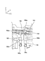
図1は、本発明による現像装置を備えた画像形成装置の要部構成を概略的に示す要部構成図である。
Embodiment 1 FIG.
FIG. 1 is a main part configuration diagram schematically showing a main part configuration of an image forming apparatus provided with a developing device according to the present invention.
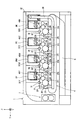
図1に示すように、画像形成装置1は、ブラック(K)、イエロー(Y)、マゼンタ(M)、シアン(C)の各色の現像ユニット2K,2Y,2M,2C(これらを総称する場合は現像ユニット2と称す)、各色のトナーカートリッジ3K,3Y,3M,3C(これらを総称する場合はトナーカートリッジ3と称す)、転写ユニット4、露光装置であるLEDヘッド5K,5Y,5M,5C(これらを総称する場合はLEDヘッド5と称す)、記録媒体としての記録用紙を収納・供給する給紙カセット6、記録用紙にトナー像を定着させる定着ユニット7等を備える。
As shown in FIG. 1, the image forming apparatus 1 includes black (K), yellow (Y), magenta (M), and cyan (C) developing
現像ユニット2は、転写ユニット4の記録用紙の搬送路に沿って、供給側から排出側に向かって、現像ユニット2K、現像ユニット2C、現像ユニット2M、現像ユニット2Yの順に配列され、後述するバスケット150(図5,6参照)により一体化された現像装置50(図2)として、画像形成装置1本体に対して着脱自在に構成されている。尚、画像形成装置1の現像装置50のように、着脱可能な或いは可動な構成要素の個々に対して、その構成要素を除いた部分を画像形成装置1本体と称す場合がある。
The developing
トナーカートリッジ3K,3Y,3M,3C(図14参照)は、未使用トナー40K,40Y,40M,40C(これらを総称する場合は未使用トナー40と称す)を収容するトナー収容部31K,31Y,31M,31C(これらを総称する場合はトナー収容部31と称す)を備えている。そして、対応する各現像ユニット2K,2Y,2M,2Cの上部において独立して着脱自在に構成され、装着された状態で、未使用トナーを対応する現像ユニット2に供給する。
The
現像ユニット2K,2Y,2M,2Cは、いずれも同じ構造であり、像担持体である感光体21K,21Y,21M,21C(これらを総称する場合は感光体21と称す)、帯電ローラ22K,22Y,22M,22C(これらを総称する場合は帯電ローラ22と称す)、感光体21を現像する現像ローラ23k,23y,23m,23c(これらを総称する場合は現像ローラ23と称す)、現像ローラ23上にトナー層を形成する現像ブレード24K,24Y,24M,24C(これらを総称する場合は現像ブレード24と称す)、現像ローラ23にトナーを供給する供給ローラ25K,25Y,25M,25C(これらを総称する場合は供給ローラ25と称す)、転写されなかった感光体21上の残留トナーを除去するクリーニングブレード26K、26Y,26M,26C(これらを総称する場合はクリーニングブレード26と称す)、及び第1搬送部27K,27Y,27M,27C(これらを総称する場合は第1搬送部27と称す)等を備える。尚、クリーニングブレード26と第1搬送部27とが清掃手段に相当する。
The developing
各第1搬送部27は、各クリーニングブレード26によって除去された廃棄トナーを感光体軸方向の図1の紙面上方(後述するY軸のプラス方向)に向けて搬送する。図1に示す搬送手段に相当する第2搬送部28は、後述するバスケット150((図5,6参照)に備えられ、後述するように各第1搬送部27より送られてきた廃棄トナーを一括して現像ユニット2の配列方向最上流に配置される廃棄トナー収容器32まで搬送する。廃棄トナー収容部32は、第2搬送部28により搬送された廃棄トナーを収容し、トナーカートリッジ3Kに対して着脱自在に設けられている(図3、図12参照)。
Each first transport unit 27 transports the waste toner removed by each
現像装置50(図2)、4つのトナーカートリッジ3、及び廃棄トナー収容部32等は何れも交換ユニットであり、トナーが消費されたり構成部品が劣化したりして寿命がきたときにいずれも交換することができる。
The developing device 50 (FIG. 2), the four
尚、図1中のX、Y、Zの各軸は、記録用紙が4つの現像ユニット2を通過する際の搬送方向にX軸をとり、各感光体21の回転軸方向にY軸をとり、これら両軸と直交する方向にZ軸をとっている。また、後述する他の図においてX、Y、Zの各軸が示される場合、これらの軸方向は、共通する方向を示すものとする。即ち、各図のXYZ軸は、各図の描写部分が、図1に示す画像形成装置1を構成する際の配置方向を示している。またここでは、Z軸が略鉛直方向となるように配置されるものとする。
Note that the X, Y, and Z axes in FIG. 1 take the X axis in the transport direction when the recording paper passes through the four developing
図2は、本発明による現像装置の実施の形態1の外観斜視図である。同図に示すように、現像装置50は、各色の現像ユニット2K,2C,2M,2Yを等ピッチで配列し、それらの周辺を囲うようにバスケット150を配設している。即ち、現像装置50は、4つの現像ユニット2(図4参照)と、これらを後述するようにある程度の自由度を保って一体的に保持するバスケット150(図5,6参照)を備え、画像形成装置1本体に対して着脱自在に装着される。各色の現像ユニット2K,2C,2M,2Yは、それぞれ対応するトナーカートリッジ3K,3Y,3M,3Cを上部に着脱自在に装着し、各トナーカートリッジ3から未使用トナー40(図1)の供給を受けるように構成されている。尚、図3は、各現像ユニット2K,2C,2M,2Yに、それぞれ対応するトナーカートリッジ3K,3Y,3M,3Cが装着されている状態を示す外観斜視図である。
FIG. 2 is an external perspective view of Embodiment 1 of the developing device according to the present invention. As shown in the figure, in the developing
次に現像ユニット2の構成について説明する。各色の現像ユニット2は、共に同じ構造を成しているため、代表して1つの現像ユニットについて詳述する。
Next, the configuration of the developing
図4は、現像ユニット2の分解斜視図である。同図に示すように、現像ユニット2は、感光体21、帯電ローラ22、サイドプレートL80、サイドプレートR90、アッパフレーム100、ベースフレーム110、現像手段に相当する現像部120、除電光発光部130、及び補強プレート140とから成っている。ベースフレーム110は、感光体21の軸方向(Y軸方向)に延在し、ベースフレーム本体111、クリーニングブレード26、廃棄トナー搬送口112、クリーニングフィルム113、第1搬送部27(図1)の第1搬送路114及び第1搬送スパイラル115、搬送駆動ギア116、両サイドプレートから端部が突出する連結軸70、そして搬送アイドルギア117から成っている。感光体21は、ベースフレーム110によって回転自在に保持され、クリーニングブレード26は、その先端部が感光体21の周面に当接し、転写されずに残留する残留トナー(廃棄トナー)を第1搬送路114に掻き落す。
FIG. 4 is an exploded perspective view of the developing
図7は、図4に示すA−A断面図であり、図8は、廃棄トナー搬送口112の近傍を拡大した部分拡大斜視図である。図7の断面図に示すように、第1搬送路114は、ベースフレーム本体111、クリーニングブレード26、クリーニングフィルム113に囲まれてY軸方向に延在する空間で形成され、図8に示すように、廃棄トナー搬送口112は、円筒形状でベースフレーム本体111から突出するように第1搬送路114の一端側(Y軸プラス方向)に位置し、第1搬送スパイラル1l5が第1搬送路114と廃棄トナー搬送口112とを貫くように設置される。
7 is a cross-sectional view taken along the line AA shown in FIG. 4, and FIG. 8 is a partially enlarged perspective view in which the vicinity of the waste
図4に示すように、第1搬送スパイラル115は、廃棄トナー搬送口112ではない方の他端側で搬送駆動ギア116と係合し、搬送アイドルギア117から駆動を受けるように構成され、駆動を受けると第1搬送路114内の廃棄トナーを廃棄トナー搬送口112の方向に搬送するように、スパイラルの向き及び回転方向が設定されている。搬送アイドルギア117は、感光体21の端部に配設されているドラムギア118から駆動力を受けるようになっている。図8に示すように、廃棄トナー搬送口112は、円筒状であってその下方端部に開放部119が形成されており、第1搬送スパイラル115は、廃棄トナー搬送口112の端部よりも僅かに外側に飛び出している。従って、廃棄トナー搬送口112に搬送された廃棄トナーは、開放部119から下方に落下する。
As shown in FIG. 4, the
サイドプレートL80及びサイドプレートR90には、後述するように、バスケット150に形成された長穴ガイド151a,152a(図5参照)に嵌入して、現像ユニット2がバスケット150に対して自由度を持って保持されるための支持部80a,90a(80aのみ示す)が形成されている。
As will be described later, the side plate L80 and the side plate R90 are fitted into elongated hole guides 151a and 152a (see FIG. 5) formed in the
次にバスケット150の構成について詳しく説明する。
Next, the configuration of the
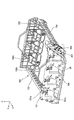
図5は、枠体に相当するバスケット150を斜め上方からみた外観斜視図であり、図6は、同じくバスケット150を、図5とは反対側の斜め上方からみた外観斜視図である。これらの図に示すように、バスケット150は、第1サイドフレーム151、第2サイドフレーム152、フロントフレーム153、及びリアフレーム154からなり、これらが四角形状の枠を形成している。第1サイドフレーム151及び第2サイドフレーム152には、4つの現像ユニット2をX軸方向に直列に保持するため、対向する位置において各一対の長穴ガイド151a,152a及び長穴ガイド151b,152bが、各現像ユニット2の保持位置に対応して4組形成されている。これらの長穴ガイドは長軸がZ軸に対して所定角度傾斜して形成されている。
FIG. 5 is an external perspective view of the
第1サイドフレーム151の長穴ガイド151aには、現像ユニット2のサイドプレートL80の支持部80a(図4)が嵌入し、第2サイドフレーム152の長穴ガイド152aには、現像ユニット2のサイドプレートR90の支持部90a(図示しない)が嵌入し、第1サイドフレーム151の長穴ガイド151b及び第2サイドフレーム152の長穴ガイド152bには、それぞれ、現像ユニット2のサイドプレートL80及びサイドプレートR90から突出する連結軸70(図2,4)が嵌入している。
The
従って、各現像ユニット2は、長穴ガイド151a、152a及び長穴ガイド151b、152bでガイドされる傾斜方向に後述する所定の可動距離L1だけ傾斜方向移動可能にバスケット150によって保持されている。これによって、図示しない離間手段によって、感光体21が転写ユニット4と接触する稼働位置と、稼働位置より上方に位置して感光体21と転写ユニット4とが離間する待機位置との間で各現像ユニット2を上下移動させることが可能となり、印字しないときなどには、長寿命化のために待機位置に移動することが可能となる。
Accordingly, each developing
但し、ブラック(K)の現像ユニット2Kは、ここでは上下移動しない構成となっており、このため長穴ガイドにする必要がないため該当部が略円形状の孔となっている。
However, the black (K) developing
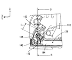
図9は、図6に2点鎖線で囲んだ廃棄トナー受け口160近傍の部分拡大図であり、図10は、現像ユニット2を実装し、現像ユニット2が稼働位置にあるときの廃棄トナー搬送口112(図4参照)の周辺を図9とは反対側の第1サイドフレーム151の外側から見た斜視図であり、図11は、図10に示すB−B断面図である。但し、図10では、内部構造を示すためにカバーフレーム164(図5参照)を外した状態で示している。
9 is a partially enlarged view of the vicinity of the waste
これらの図9〜図11に示すように、第1サイドフレーム151には、現像ユニット2を実装したときの各廃棄トナー搬送口112(図4)に対向する位置に廃棄トナー受け口160を設けており、各廃棄トナー受け口160は、後述するように廃棄トナー受け口160の下方に位置している第2搬送部28と空間的につながっている。この第2搬送部28は、4つの現像ユニット2の各廃棄トナー搬送口112に対向すべく、第1サイドフレーム151の下部に延在し(例えば図2に示すようにX軸方向)、廃棄トナー収容部32(図1)につながる第2搬送路144と、第2搬送路144内にあって、各現像ユニット2の廃棄トナー搬送口112から第2搬送路144に落下した廃トナーを廃棄トナー収容部32に向けて搬送する第2搬送スパイラル145を有し、図5、図11に示すように、これらを覆うカバーフレーム164によって覆われている。
As shown in FIGS. 9 to 11, the
廃棄トナー受け口160は、円筒形状の廃棄トナー搬送口112を受入れた状態で、前記した現像ユニット2の傾斜方向移動を許容するため、長穴ガイド151a,151bと同方向に長軸を有する長穴状に形成されている。ここでは、現像ユニット2の移動量に合わせて、受入れた廃棄トナー搬送口112が長軸方向に可動距離L1(図10)だけ移動できるように構成されている。
The waste
図11に示すように、現像ユニット2がバスケット150に装着された状態で、現像ユニット2のサイドプレートL80とバスケット150の第1サイドフレーム151との間には、隙間L2が生じている。この隙間L2には、長穴状の廃棄トナー受け口160に嵌入した廃棄トナー搬送口112から排出される廃トナーが、バスケット150内に漏れないように、スポンジやゴム等の柔らかい弾性部材で形成されたシール部材161が配置されている。このシール部材161は、隙間L2よりも厚い厚さTと、図9に示すように、長穴状の廃棄トナー受け口160と合致する長孔161aを備え、これらが合致するように、一方の側面161cが両面テープによって第1サイドフレーム151に貼り付けられ、他方の側面161bがサイドプレートL80に押し当てられている。
As shown in FIG. 11, a gap L <b> 2 is generated between the side plate L <b> 80 of the developing
また、シール部材161は、バスケット150に装着された現像ユニット2が可動距離L1の範囲で移動するとき、その移動の妨げにならないように、スポンジやゴムのような柔らかい素材で形成され、更にこの移動によってシール部材161の他方の側面161bとサイドプレートL80との間に隙間が生じて廃トナーもれが生じないように、厚さT、可動距離L1、及び隙間L2の関係が
T≧L1十L2 ・・・(1)
となるように設定されている。これにより、サイドプレートL80に対するシール部材161の他方の側面161bの押圧部の位置をずらすことなく密着したまま、現像ユニット2の移動を許容することが可能となる。
The
It is set to become. Accordingly, it is possible to allow the movement of the developing
更にこれにより、厚さTのシール部材161が隙間L2の間に圧縮されて配設され、シール部材がサイドプレートL80にしっかり密着すると共に、現像ユニット2を反対側の第2サイドフレーム152側へ付勢(押し当て)する力が生じ、現像ユニットのガタツキを抑えることができる。
Further, by this, the
以上のように現像装置50は、画像形成装置1本体に装着される段階で、各現像ユニット2の第1搬送路114とバスケット150の第2搬送路144は、シール部材161によって、各現像ユニット2とバスケット150の第1サイドフレーム151との間で弾性的に密封される。即ち、バスケット150と、バスケット150によって自由度をもって保持されている各現像ユニット2間は、シール部材161によって空間的な接続が、自由度を許容すべく弾性的に構成されている。
As described above, when the developing
以上の構成において、感光体21が転写ユニット4と接触する稼働位置と感光体21と転写ユニット4とが離間する待機位置との間で、各現像ユニット2が上下移動するときの動作について説明する。
In the above configuration, the operation when each developing
図13は、前記した図11と同位置において、バスケット150に装着した転写ユニット4が待機位置に移動したときの廃棄トナー搬送口112周辺の状態を示す動作説明図である。尚、図11は、前記したように、バスケット150に装着した転写ユニット4が稼働位置にあるときの廃棄トナー搬送口112周辺の状態を示す動作説明図である。
FIG. 13 is an operation explanatory view showing a state around the waste
転写ユニット4が図11に示す稼働位置にあって、通常の印刷動作を行うとき、図4に示す、感光体21が回転し、搬送アイドルギア117、搬送駆動ギア116、第1搬送スパイラル115が連動して回転することにより、廃棄トナーは廃棄トナー搬送口112まで搬送され、廃棄トナー受け口160(図10)にて開放部119より落下する。このとき、シール部材161が設けられているため、廃棄トナーは廃棄トナー搬送口112や廃棄トナー受け口160からバスケット150内に漏れることはない。
When the transfer unit 4 is in the operating position shown in FIG. 11 and performs a normal printing operation, the
またシール部材161は、前記した不等式(1)を満たす厚さTを有し、シール部材161の一方の側面161cが両面テープで第1サイドフレーム151に固定され、他方の側面161bがサイドプレートL80に押し当てられているため、現像ユニット2の感光体21が転写ユニット4(図1)から離れる待機位置に向けて移動した場合、この間圧縮状態を保ったまま移動し、図13に示すように、他方の側面161bが摩擦によりサイドプレートL80に対してずれることなく追従して移動する。そのため現像ユニット2が移動中や待機位置にあっても、廃棄トナーが、廃棄トナー搬送口112や廃棄トナー受け口160からバスケット150内に漏れることはない。
The
更に、現像ユニット2を反対側の第2サイドフレーム152側へ付勢(押し当て)する力が維持され、現像ユニット2が移動中や待機位置にあっても、現像ユニットのガタツキを抑えることができる。
Further, the force for urging (pressing) the developing
一方、シール部材161の厚さTが前記した不等式(1)を満たさずに、薄く設定されている場合、他方の側面161bがサイドプレートL80に押し当てられる力が弱くなり、現像ユニット2が待機位置に向けて移動した場合、この間圧縮状態が十分保てず、更には圧縮状態でなくなるため、他方の側面161bが摩擦によりサイドプレートL80に対してずれることなく追従して移動できなくなる。そのため、他方の側面161bとサイドプレートL80との間ですべりが発生し、移動するシール部材161とサイドプレートL80との間から廃棄トナーが漏れやすくなる。また、シール部材161が硬いと、同様に他方の側面161bはサイドプレートL80に追従できずにすべりが発生し、廃棄トナーが漏れやすくなる。
On the other hand, when the thickness T of the
以上のように、本実施の形態の現像装置によれば、バスケット150に対して現像ユニット2が稼働位置と待機位置との間で上下移動する際に、廃棄トナーが搬送される、各現像ユニット2の第1搬送路114とバスケット150の第2搬送路144は、両者間においてシール部材161によって外部から略密封した状態が保たれ、廃棄トナーもれを防止することができき、更に、バスケット150に対する現像ユニット2のガタツキを抑えることができる。
As described above, according to the developing device of the present embodiment, each developing unit to which waste toner is conveyed when the developing
実施の形態2.
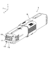
図14は、トナーカートリッジ3の外観斜視図である。同図に示すようにトナーカートリッジ3の、転写ユニット2のサイドプレートL80に対向する長手方向(Y軸方向)端部に設けられた記憶素子基板170には、記憶素子171と接点部172,173が配設されている。
FIG. 14 is an external perspective view of the
図15は、サイドプレートL80の外観斜視図であり、図16は、図15に示すC−C断面図である。 15 is an external perspective view of the side plate L80, and FIG. 16 is a cross-sectional view taken along the line CC shown in FIG.
サイドプレートL80には、第2の導通部材に相当するコンタクトスプリング81,82が設けられている。これらのコンタクトスプリング81,82の一端部81a,82aは、サイドプレートL80の内側(サイドプレートR90に対向する側)に延在し、ユーザがトナーカートリッジ3を現像ユニット2にセットしたときに、それぞれある押圧で接点部172,173(図14)に接触する。一端部81a,82a及び接点部172,173は、各接触部及び接触部周辺に金メッキを施している。
The side plate L80 is provided with contact springs 81 and 82 corresponding to the second conductive member. One
第1導電部に相当するコンタクトスプリング81,82は、それぞれ電気的接続部81c,82cを介した他端部に圧縮コイルスプリング部81b,82bを形成し、これらの圧縮コイルスプリング部81b,82bは、それぞれサイドプレートL80に形成されたコイルスプリングポスト85,86に嵌め込まれている。図16に示すように、コイルスプリングポスト85,86は、先端がL字型(くさび形状)になっている一対のフック85a,85b、86a,86bが互いに背中向きになるように隙間Mを空けて形成されている。
The contact springs 81 and 82 corresponding to the first conductive portion are formed with compression
図17は、図6に示すバスケット150の第1サイドフレーム151の内側(第2のサイドフレーム152に対向する側)に配設されたコンタクトスプリング183,184の周辺の拡大図であり、図18は、図2に2点鎖線で囲んだコンタクトスプリング183,184の近傍において、カバープレート190を外した状態の部分拡大図であり、図19は、図18に示すD−D断面図である。図20は、第1サイドフレーム151に備えられたコンタクトスプリング200,201の周辺を第1サイドフレーム151の内側(第2のサイドフレーム152に対向する側)から見た外観図であり、図21は、同部分を反対側(外側)から見た斜視図であり、図5に2点鎖線で囲んだコンタクトスプリング200,201の周辺の部分拡大図に相当する。
17 is an enlarged view of the periphery of contact springs 183 and 184 disposed on the inner side of the first side frame 151 (the side facing the second side frame 152) of the
コンタクトスプリング183,184は、図6に示すように、各現像ユニット2を実装したときのコイルスプリングポスト85,86に対向する位置にそれぞれ配置されている。また、第1のサイドフレーム151の内側には、各色位置のコンタクトスプリング183,184と後述するような電気的な接続をとるべく、第1サイドフレーム151の上部に延在(X軸方向)する第2導電部に相当する導線180,181が配設され、これら導線の各一端部が、画像形成装置1本体との接点部であるコンタクトスプリング200,201(図21)の各コイルスプリング部200a,201a(図20)にそれぞれ電気的に接続されている。
As shown in FIG. 6, the contact springs 183 and 184 are arranged at positions facing the coil spring posts 85 and 86 when the developing
図17に示すように、各色位置に配設しているコンタクトスプリング183,184は、それぞれ、第1圧縮コイルスプリング部183a,184a、第2圧縮コイルスプリング部183b,184b、及び第3圧縮コイルスプリング部183c、184cとで形成される。第1圧縮コイルスプリング部183a,184aは、それぞれ導線180,181に直交する方向に伸縮可能であり、第1サイドフレーム151への実装と同時にそれぞれが導線180、181を挟み込みながら圧縮される。第2圧縮コイルスプリング部183b,184bは、現像ユニット2の移動方向に伸縮可能であり、その自由長L3は密着高さ(コイルスプリングが密着するまで圧縮した状態でのコイルスプリングの長さ)L4と現像ユニット2の可動距離L1を足したよりも長くなっている。即ち、
L3≧L4+L1 ・・・(2)
の不等式を満たすように設定されている。
As shown in FIG. 17, the contact springs 183 and 184 disposed at the respective color positions are respectively the first compression
L3 ≧ L4 + L1 (2)
Is set to satisfy the inequality.
第3圧縮コイルスプリング部183c,184cは、コイルスプリングポスト85、86への挿入方向に伸縮可能で、コンタクトスプリング81,82の圧縮コイルスプリング部81b,82bの自由長L5(図16)と第3圧縮コイルスプリング部183c,184cの自由長L6を足したよりもコイルスプリングポスト85、86の規制長L7(図16)が短く、且つ圧縮コイルスプリング部81b,82bの密着高さL8と第3圧縮コイルスプリング部183c,184cの密着高さL9を足したよりもコイルスプリングポスト85、86の規制長L7が長くなっている。即ち、
L5十L6≧L7≧L8十L9 ・・・(3)
の不等式を満たすように設定されている。
The third compression
L5 + L6 ≧ L7 ≧ L8 + L9 (3)
Is set to satisfy the inequality.
これらの条件のもと、第3圧縮コイルスプリング部183c,184cは、図18,19に示すように、それぞれ対応するコンタクトスプリング81,82の圧縮コイルスプリング部81b,82bと共にコイルスプリングポスト85、86へ挿入され、カバープレート190(図2、図19)により固定される。
Under these conditions, the third compression
上記不等式(3)を満たすことにより、第3圧縮コイルスプリング部183cと圧縮コイルスプリング部81b及び第3圧縮コイルスプリング部184cと圧縮コイルスプリング部82bは、それぞれ圧接して電気的に接続した状態を保ち、また上記不等式(2)を満たすことにより、現像ユニット2の支持部80a(図4)をバスケット150の長穴151a(図5)の下端に付勢(押し当て)することができるので、バスケット150は、ガタつきを抑えつつ各現像ユニット2を保持することが可能となる。
尚、図19は、第3圧縮コイルスプリング部183c,184c及びコンタクトスプリング81,82の圧縮コイルスプリング部81b,82bが共に密着高さに圧縮した時の状態を示している。
By satisfying the inequality (3), the third compression
FIG. 19 shows a state where the third compression
カバープレート190は、図19に示すように、押さえリブ190a及び190bを備えており、これらが対応するフック85a,85b、及び86a,86bの隙間Mに入り込むようになっている。コイルスプリングポスト85、86の規制部幅D、フック85a,85b及び、86a,86bの隙間M、カバープレート190のリブ幅H、フック85a,85b及び、86a,86bのL字先端部幅W、コンタクトスプリング81,82の圧縮コイルスプリング部81b,82bの内径d1、及びコンタクトスプリング183,184の第3圧縮コイルスプリング部183c,184cの内径d2の各寸法の大小関係は、下記の各不等式を満たすように設定される。
d1≧D、 d2≧D、 W−M+H≧d1、 W−M+H≧d2
As shown in FIG. 19, the
d1 ≧ D, d2 ≧ D, W−M + H ≧ d1, W−M + H ≧ d2
これにより、圧縮コイルスプリング部81b及び第3圧縮コイルスプリング部183cをコイルスプリングポスト85にはめ込み、圧縮コイルスプリング部82b及び第3圧縮コイルスプリング部184cをコイルスプリングポスト86にはめ込み、更に、カバープレート190を装着することによって、これらのコイルスプリングが各コイルスプリングポストから外れるのを防止することができる。
Accordingly, the compression
図20,21に示すように、コンタクトスプリング200,201は、コイルスプリング部200a、201aと接点部200b、201bとから成っており、第1サイドフレーム151への実装と同時に、コイルスプリング部200a、201aは、それぞれ導線180、181を挟み込みながら圧縮され電気的な接続が確保され、接点部200b、201bは、第1サイドフレーム151に形成された開口部を介して外側に臨み、所定の弾性を保ったまま図21に示すように、第1サイドフレーム151の表面から突出した状態に配置される。接点部200b、201bは、現像装置50(図2参照)が画像形成装置1本体に装着されると、画像形成装置1本体に設けられた図示せぬ接点部とある押圧で当接して電気的な接続が確保される。接点部200b、201b及び接点部200b、201bの周辺は金メッキが施されている。
As shown in FIGS. 20 and 21, the contact springs 200 and 201 are composed of
以上のように現像装置50は、画像形成装置1本体に装着される段階で、各現像ユニット2のコンタクトスプリング81,82とバスケット150の第1サイドフレーム151の各コンタクトスプリング183,184とは、コイルスプリングポスト85,86を共通軸として弾性的且つ電気的に接続され、更に各コンタクトスプリング183,184の第2圧縮コイルスプリング部の伸縮性によって現像ユニット2の移動方向においても弾性的に接続されている。即ち、バスケット150と、バスケット150によって自由度をもって保持されている各現像ユニット2間は、コンタクトスプリング81,82とコンタクトスプリング183,184によって電気的な接続が自由度を許容すべく弾性的に構成されている。
As described above, when the developing
以上の構成において、感光体21が転写ユニット4と接触する稼働位置と感光体21と転写ユニット4とが離間する待機位置との間で、各現像ユニット2が上下移動するときの動作について説明する。
In the above configuration, the operation when each developing
図22は、前記した図18と同位置において、バスケット150に装着した現像ユニット2が稼働位置にあるときのコンタクトスプリング183,184の周辺の状態を示す動作説明図であり、図23は、同じく前記した図18と同位置において、バスケット150に装着した現像ユニット2が待機位置にあるときのコンタクトスプリング183,184の周辺の状態を示す動作説明図である。尚、図22,23では、現像ユニット2にはトナーカートリッジ3が装着され、またバスケット150の第1サイドフレーム151にはカバープレート190が装着された状態を示している。
FIG. 22 is an operation explanatory view showing a state around the contact springs 183 and 184 when the developing
トナーカートリッジ3が現像装置50の現像ユニット2に装着されると、接点部172,173(図14)がそれぞれコンタクトスプリング81,82の各一端部81a,82a(図15)に当接して電気的に接続する。コンタクトスプリング81,82は、その圧縮コイルスプリング部81b,82bが、それぞれコンタクトスプリング183,184(図17)の各第3圧縮コイルスプリング部183c,184cと、フック85a,85b、86a,86b(図19)を有するコイルスプリングポスト85,86にて圧接して電気的に接続し、カバープレート190の押さえリブ190a,190bにより確実に固定されている。
When the
更に、現像ユニット2の移動方向に伸縮可能で、上記不等式(2)を満たすように設定された第2コイルスプリング部183b,184b(図17)を介した第1圧縮コイルスプリング部183a,184aは、それぞれ導線180,181と、導線180,181はそれぞれコンタクトスプリング200,201(図21)と電気的に接続して固定されている。
Furthermore, the first compression
このため、現像ユニット2が、図22に示す稼働位置と図23に示す待機位置間で上下移動した場合でも、第2圧縮コイルスプリング部183b,184bが圧縮した状態を保ったまま移動を許容する。従って、移動時、更には待機位置に移動した場合においても、トナーカートリッジ3の接点部172,173と画像形成装置1本体との接点部であるコンタクトスプリング200,201との電気的な接続を維持しつつ、現像ユニットの支持部80a(図4)を長穴151a(図5)の下端に付勢(押し当て)することができるので、バスケット150は、ガタつきを抑えつつ各現像ユニット2を保持することが可能となる。
For this reason, even when the developing
以上のように、本実施の形態の現像装置によれば、バスケット150に対して現像ユニット2が稼働位置と待機位置との間で上下移動する際に、バスケット150に、圧縮したまま現像ユニット2の移動に追従できるコンタクトスプリング183,184を設けているため、バスケット150と各現像ユニット2間の電気的な接続を保ち、且つ現像ユニット2のガタつきを抑えることができる。
As described above, according to the developing device of the present embodiment, when the developing
また、前記した特許請求の範囲、及び実施の形態の説明において、「上」、「下」、「左」、「右」、「前」、「後」といった言葉を使用したが、これらは便宜上であって、画像形成装置を配置する状態における絶対的な位置関係を限定するものではない。 In the claims and the description of the embodiments, the words “up”, “down”, “left”, “right”, “front”, “back” are used for convenience. However, the absolute positional relationship in the state where the image forming apparatus is arranged is not limited.
前記した各実施の形態では、画像形成装置が電子写真プリンタである場合について説明したが、本発明はこれに限定されず、ファクシミリ装置、複写機、それらを複合的に持つ複合機等にも適用可能である。 In each of the above-described embodiments, the case where the image forming apparatus is an electrophotographic printer has been described. However, the present invention is not limited to this, and the present invention is also applicable to a facsimile machine, a copier, a multi-function machine having them in combination, and the like. Is possible.
1 画像形成装置、 2 現像ユニット、 3 トナーカートリッジ、 4 転写ユニット、 5 LEDヘッド、 6 給紙カセット、 7 定着ユニット、 21 感光体、 22 帯電ローラ、 23 現像ローラ、 24 現像ブレード、 25 供給ローラ、 26 クリーニングブレード、 27 第1搬送部、 28 第2搬送部、 31 トナー収容部、 32 廃棄トナー収容器、 40 未使用トナー、 50 現像装置、 70 連結軸、 80 サイドプレートL、 80a 支持部、 81 コンタクトスプリング、 81a 一端部、 81b 圧縮コイルスプリング部、 81c 電気的接続部、 82 コンタクトスプリング、 82a 一端部、 82b 圧縮コイルスプリング部、 82c 電気的接続部、 85 スプリングポスト、 85a フック、 85b フック、 86 スプリングポスト、 86a フック、 87b フック、 90 サイドプレートR、 90a 支持部、 100 アッパフレーム、 110 ベースフレーム、 111 ベースフレーム本体、 112 廃棄トナー搬送口、 113 クリーニングフィルム、 114 第1搬送路、 115 第1搬送スパイラル、 116 搬送駆動ギア、 117 搬送アイドルギア、 118 ドラムギア、 119 開放部、 120 現像部、 130 除電光発光部、 140 補強プレート、 144 第2搬送路、 145 第2搬送スパイラル、 150 バスケット、 151 第1サイドフレーム、 151a 長穴ガイド、 151b 長穴ガイド、 152 第2サイドフレーム、 152a 長穴ガイド、 152b 長穴ガイド、 160 廃棄トナー受け口、 161 シール部材、 161a 長孔、 161b 他方の側面、 161c 一方の側面、 164 カバーフレーム、 170 記憶素子基板、 171 記憶素子、 172 接点部、 173 接点部、 180 導線、 181 導線、 183 コンタクトスプリング、 183a 第1圧縮コイルスプリング部、 183b 第2圧縮コイルスプリング部、 183c 第3圧縮コイルスプリング部、 184 コンタクトスプリング、 184a 第1圧縮コイルスプリング部、 184b 第2圧縮コイルスプリング部、 184c 第3圧縮コイルスプリング部、 190 カバープレート、 200 コンタクトスプリング、 200a コイルスプリング部、 200b 接点部、 201 コンタクトスプリング、 201a コイルスプリング部、 201b 接点部。 DESCRIPTION OF SYMBOLS 1 Image forming apparatus, 2 Developing unit, 3 Toner cartridge, 4 Transfer unit, 5 LED head, 6 Paper feed cassette, 7 Fixing unit, 21 Photoconductor, 22 Charging roller, 23 Developing roller, 24 Developing blade, 25 Supply roller, 26 cleaning blade, 27 first transport section, 28 second transport section, 31 toner storage section, 32 waste toner container, 40 unused toner, 50 developing device, 70 connecting shaft, 80 side plate L, 80a support section, 81 Contact spring, 81a one end, 81b compression coil spring, 81c electrical connection, 82 contact spring, 82a one end, 82b compression coil spring, 82c electrical connection, 85 spring post, 85a Hook, 85b hook, 86 spring post, 86a hook, 87b hook, 90 side plate R, 90a support, 100 upper frame, 110 base frame, 111 base frame body, 112 waste toner transport port, 113 cleaning film, 114 first 1 transport path, 115 first transport spiral, 116 transport drive gear, 117 transport idle gear, 118 drum gear, 119 opening section, 120 developing section, 130 static elimination light emitting section, 140 reinforcing plate, 144 second transport path, 145 second Transport spiral, 150 basket, 151 1st side frame, 151a slot guide, 151b slot guide, 152 second side frame, 152a slot guide, 152b slot Guide, 160 Waste toner receptacle, 161 Seal member, 161a Long hole, 161b The other side, 161c One side, 164 Cover frame, 170 Storage element substrate, 171 Storage element, 172 Contact part, 173 Contact part, 180 Conductor, 181 Conductor, 183 contact spring, 183a first compression coil spring part, 183b second compression coil spring part, 183c third compression coil spring part, 184 contact spring, 184a first compression coil spring part, 184b second compression coil spring part, 184c Third compression coil spring part, 190 cover plate, 200 contact spring, 200a coil spring part, 200b contact part, 201 contact sp Ring, 201a coil spring part, 201b contact part.
Claims (9)
複数の前記各現像ユニットを、個別に所定の範囲で移動可能に且つ一体的に保持する枠体と、
前記枠体に配設されて、前記清掃手段により清掃される排出物を搬送する搬送手段と、
前記清掃手段と前記搬送手段との間をシールするシール部材と
を有し、
前記シール部材は、弾性部材からなり、前記現像ユニットの可動距離よりも大きい圧縮量で実装されることを特徴とする現像装置。 A developing device comprising a plurality of developing units each including an image carrier, a developing unit that develops the electrostatic latent image formed on the image carrier with a developer, and a cleaning unit that cleans the image carrier,
A frame that holds each of the plurality of developing units individually and in a predetermined range so as to be movable, and
A transporting means for transporting the discharged material disposed on the frame and cleaned by the cleaning means;
A sealing member that seals between the cleaning means and the conveying means;
The developing device according to claim 1, wherein the seal member is made of an elastic member and is mounted with a compression amount larger than a movable distance of the developing unit.
前記導通手段は、前記枠体に設けられた第1の導通部材と、前記現像ユニットに設けられた第2の導通部材とからなり、前記第1の導通部材と前記第2の導通部材との少なくとも一方が弾性的に形成された導電性弾性部材であり、お互いに弾性的に接続されることを特徴とする請求項1記載の現像装置。 A conducting means for electrically conducting the frame and a storage element provided in a developer container removable from the developing unit;
The conducting means includes a first conducting member provided on the frame body and a second conducting member provided on the developing unit, and the first conducting member and the second conducting member are The developing device according to claim 1, wherein at least one of the elastic members is an elastic elastic member that is elastically connected to each other.
複数の前記各現像ユニットを、個別に所定の範囲で移動可能に且つ一体的に保持する枠体と、
前記枠体と前記現像ユニットとの間を、弾性的に接続する弾性接続手段と
を有し、
前記清掃手段は、前記像担持体から除いた現像剤を前記枠体に導く第1搬送路を有し、
前記枠体は、前記第1搬送路から受けた前記現像剤を所定方向に搬送する第2搬送路を有し、
前記弾性接続手段は、前記第1搬送路と前記第2搬送路との接続部を覆うシール部材であって、圧縮状態で備えられて前記現像ユニットを前記枠体の一部に付勢することを特徴とする現像装置。 A developing device comprising a plurality of developing units each including an image carrier, a developing unit that develops the electrostatic latent image formed on the image carrier with a developer, and a cleaning unit that cleans the image carrier,
A frame that holds each of the plurality of developing units individually and in a predetermined range so as to be movable, and
Elastic connection means for elastically connecting between the frame and the development unit;
The cleaning means has a first transport path that guides the developer removed from the image carrier to the frame,
The frame has a second conveyance path for conveying the developer received from the first conveyance path in a predetermined direction;
The elastic connection means is a seal member that covers a connection portion between the first conveyance path and the second conveyance path, and is provided in a compressed state to urge the developing unit toward a part of the frame body. A developing device.
T≧L1十L2
であることを特徴とする請求項3記載の現像装置。 When the movable distance of the movable range is L1, the gap between the frame on which the seal member is disposed and the developing unit is L2, and the thickness of the seal member is T,
T ≧ L1 + L2
The developing device according to claim 3, wherein:
前記枠体は、外部に接続する第2の端子を備え、
前記弾性接続手段が、前記第1の端子と前記第2の端子とを電気的に接続するスプリングであることを特徴とする請求項3又は4記載の現像装置。 The developing unit is detachably equipped with a developer container having a first terminal,
The frame includes a second terminal connected to the outside,
5. The developing device according to claim 3, wherein the elastic connecting means is a spring for electrically connecting the first terminal and the second terminal.
Lb≧Lc+La
であることを特徴とする請求項6記載の現像装置。 When La movable distance of the movable range, the natural length of the coil spring Lb, the adhesion length of a state where the coil scan pulling is compressed to close contact was Lc,
Lb ≧ Lc + La
The developing device according to claim 6, wherein:
Priority Applications (3)
| Application Number | Priority Date | Filing Date | Title |
|---|---|---|---|
| JP2010019038A JP5150656B2 (en) | 2010-01-29 | 2010-01-29 | Developing device and image forming apparatus |
| EP11152209A EP2363751A1 (en) | 2010-01-29 | 2011-01-26 | Developing apparatus and image forming apparatus |
| US13/014,960 US8649705B2 (en) | 2010-01-29 | 2011-01-27 | Developing apparatus and image forming apparatus |
Applications Claiming Priority (1)
| Application Number | Priority Date | Filing Date | Title |
|---|---|---|---|
| JP2010019038A JP5150656B2 (en) | 2010-01-29 | 2010-01-29 | Developing device and image forming apparatus |
Publications (3)
| Publication Number | Publication Date |
|---|---|
| JP2011158629A JP2011158629A (en) | 2011-08-18 |
| JP2011158629A5 JP2011158629A5 (en) | 2011-09-29 |
| JP5150656B2 true JP5150656B2 (en) | 2013-02-20 |
Family
ID=43902878
Family Applications (1)
| Application Number | Title | Priority Date | Filing Date |
|---|---|---|---|
| JP2010019038A Active JP5150656B2 (en) | 2010-01-29 | 2010-01-29 | Developing device and image forming apparatus |
Country Status (3)
| Country | Link |
|---|---|
| US (1) | US8649705B2 (en) |
| EP (1) | EP2363751A1 (en) |
| JP (1) | JP5150656B2 (en) |
Families Citing this family (4)
| Publication number | Priority date | Publication date | Assignee | Title |
|---|---|---|---|---|
| KR101860028B1 (en) * | 2011-12-16 | 2018-07-06 | 에이치피프린팅코리아 주식회사 | Image forming apparatus |
| JP5525558B2 (en) * | 2012-02-24 | 2014-06-18 | 株式会社沖データ | Connecting mechanism, developing device, and image forming apparatus |
| JP6459685B2 (en) * | 2015-03-24 | 2019-01-30 | 富士ゼロックス株式会社 | Driving force transmission mechanism and image forming apparatus |
| JP6957205B2 (en) * | 2017-05-31 | 2021-11-02 | キヤノン株式会社 | Cartridge and image forming equipment |
Family Cites Families (17)
| Publication number | Priority date | Publication date | Assignee | Title |
|---|---|---|---|---|
| JPH0384564A (en) * | 1989-08-29 | 1991-04-10 | Canon Inc | Image forming device |
| JP3150089B2 (en) * | 1997-10-27 | 2001-03-26 | 静岡日本電気株式会社 | Battery removal electrode structure |
| JP2000321843A (en) * | 1999-05-07 | 2000-11-24 | Konica Corp | Color image forming device |
| JP3958315B2 (en) | 2004-10-07 | 2007-08-15 | キヤノン株式会社 | Electrophotographic image forming apparatus |
| JP4626370B2 (en) * | 2005-04-11 | 2011-02-09 | ブラザー工業株式会社 | Image forming apparatus |
| KR100633097B1 (en) * | 2005-07-22 | 2006-10-11 | 삼성전자주식회사 | Image forming process module and image forming apparatus having the same |
| JP2007148193A (en) * | 2005-11-30 | 2007-06-14 | Ricoh Co Ltd | Toner exhauster, image forming apparatus, and process cartridge |
| JP3997247B2 (en) * | 2005-12-01 | 2007-10-24 | キヤノン株式会社 | Electrophotographic image forming apparatus |
| JP2007256352A (en) * | 2006-03-20 | 2007-10-04 | Brother Ind Ltd | Image forming apparatus and developing cartridge |
| US7856192B2 (en) * | 2006-12-28 | 2010-12-21 | Canon Kabushiki Kaisha | Process cartridge and electrophotographic image forming apparatus |
| JP2008203566A (en) * | 2007-02-20 | 2008-09-04 | Brother Ind Ltd | Image forming apparatus, process cartridge and developing cartridge |
| JP4985030B2 (en) * | 2007-03-29 | 2012-07-25 | ブラザー工業株式会社 | Image forming apparatus |
| US7831190B2 (en) * | 2007-07-04 | 2010-11-09 | Samsung Electronics Co., Ltd. | Cover opening and closing unit, image forming apparatus having the same, and method of removing and mounting cover |
| JP4561846B2 (en) * | 2008-02-29 | 2010-10-13 | ブラザー工業株式会社 | Image forming apparatus |
| JP4600535B2 (en) * | 2008-06-27 | 2010-12-15 | ブラザー工業株式会社 | Image forming apparatus |
| JP4780627B2 (en) * | 2008-06-27 | 2011-09-28 | 株式会社沖データ | Developing device and image forming apparatus |
| JP4384251B1 (en) * | 2009-03-11 | 2009-12-16 | キヤノン株式会社 | Developing cartridge, process cartridge, and electrophotographic image forming apparatus |
-
2010
- 2010-01-29 JP JP2010019038A patent/JP5150656B2/en active Active
-
2011
- 2011-01-26 EP EP11152209A patent/EP2363751A1/en not_active Withdrawn
- 2011-01-27 US US13/014,960 patent/US8649705B2/en active Active
Also Published As
| Publication number | Publication date |
|---|---|
| EP2363751A1 (en) | 2011-09-07 |
| US20110188886A1 (en) | 2011-08-04 |
| JP2011158629A (en) | 2011-08-18 |
| US8649705B2 (en) | 2014-02-11 |
Similar Documents
| Publication | Publication Date | Title |
|---|---|---|
| JP5565011B2 (en) | Image forming apparatus | |
| JP4802872B2 (en) | Detachable cartridge and image forming apparatus | |
| JP3747195B2 (en) | Process cartridge and electrophotographic image forming apparatus | |
| AU2009233661B2 (en) | Image forming apparatus | |
| JP2006343722A (en) | Developer container, process cartridge, image forming apparatus, and manufacturing method for developer container | |
| JP2006276776A (en) | Image forming apparatus and cartridge | |
| JP5150656B2 (en) | Developing device and image forming apparatus | |
| JP4289267B2 (en) | Cartridge and image forming apparatus | |
| JP5495933B2 (en) | Developer storage device, development device, and developer supply device | |
| JP6278665B2 (en) | Image forming apparatus | |
| JP2020154010A (en) | Developing device, process cartridge, and image forming apparatus | |
| JP5171882B2 (en) | Case engaging structure and image forming apparatus | |
| JP5206145B2 (en) | Waste toner collecting container unit and image forming apparatus | |
| JP6143101B2 (en) | Powder container and image forming apparatus | |
| JP4936702B2 (en) | Image forming apparatus | |
| US7796935B2 (en) | Process cartridge and image forming apparatus including same | |
| US7539439B2 (en) | Image carrier toner unit and image forming apparatus | |
| JP4698341B2 (en) | Developing device, process cartridge, and image forming apparatus | |
| JP4968246B2 (en) | Image forming apparatus | |
| JP3592522B2 (en) | Image forming device | |
| JP4574497B2 (en) | Toner container mounting member, toner supply device, and image forming apparatus | |
| EP4318135A1 (en) | Developer storage container and image forming apparatus | |
| EP4318136A1 (en) | Developer storage container and image forming apparatus | |
| JP7333013B2 (en) | Storage container and image forming apparatus | |
| JP4914813B2 (en) | Developer container, developing unit, and image forming apparatus |
Legal Events
| Date | Code | Title | Description |
|---|---|---|---|
| A521 | Request for written amendment filed |
Free format text: JAPANESE INTERMEDIATE CODE: A523 Effective date: 20110810 |
|
| A621 | Written request for application examination |
Free format text: JAPANESE INTERMEDIATE CODE: A621 Effective date: 20110810 |
|
| A977 | Report on retrieval |
Free format text: JAPANESE INTERMEDIATE CODE: A971007 Effective date: 20111128 |
|
| A131 | Notification of reasons for refusal |
Free format text: JAPANESE INTERMEDIATE CODE: A131 Effective date: 20111206 |
|
| A521 | Request for written amendment filed |
Free format text: JAPANESE INTERMEDIATE CODE: A523 Effective date: 20120127 |
|
| A131 | Notification of reasons for refusal |
Free format text: JAPANESE INTERMEDIATE CODE: A131 Effective date: 20120612 |
|
| A521 | Request for written amendment filed |
Free format text: JAPANESE INTERMEDIATE CODE: A523 Effective date: 20120726 |
|
| TRDD | Decision of grant or rejection written | ||
| A01 | Written decision to grant a patent or to grant a registration (utility model) |
Free format text: JAPANESE INTERMEDIATE CODE: A01 Effective date: 20121113 |
|
| A61 | First payment of annual fees (during grant procedure) |
Free format text: JAPANESE INTERMEDIATE CODE: A61 Effective date: 20121203 |
|
| R150 | Certificate of patent or registration of utility model |
Ref document number: 5150656 Country of ref document: JP Free format text: JAPANESE INTERMEDIATE CODE: R150 Free format text: JAPANESE INTERMEDIATE CODE: R150 |
|
| FPAY | Renewal fee payment (event date is renewal date of database) |
Free format text: PAYMENT UNTIL: 20151207 Year of fee payment: 3 |
|
| S111 | Request for change of ownership or part of ownership |
Free format text: JAPANESE INTERMEDIATE CODE: R313111 |
|
| R350 | Written notification of registration of transfer |
Free format text: JAPANESE INTERMEDIATE CODE: R350 |