JP5149348B2 - Transmission power control method and mobile station apparatus - Google Patents
Transmission power control method and mobile station apparatus Download PDFInfo
- Publication number
- JP5149348B2 JP5149348B2 JP2010181813A JP2010181813A JP5149348B2 JP 5149348 B2 JP5149348 B2 JP 5149348B2 JP 2010181813 A JP2010181813 A JP 2010181813A JP 2010181813 A JP2010181813 A JP 2010181813A JP 5149348 B2 JP5149348 B2 JP 5149348B2
- Authority
- JP
- Japan
- Prior art keywords
- path loss
- transmission
- transmission power
- antenna
- mobile station
- Prior art date
- Legal status (The legal status is an assumption and is not a legal conclusion. Google has not performed a legal analysis and makes no representation as to the accuracy of the status listed.)
- Active
Links
- 230000005540 biological transmission Effects 0.000 title claims abstract description 400
- 238000000034 method Methods 0.000 title claims abstract description 120
- 238000005259 measurement Methods 0.000 claims description 54
- 238000012937 correction Methods 0.000 claims description 9
- 238000012935 Averaging Methods 0.000 claims description 5
- 238000012545 processing Methods 0.000 description 66
- 238000004891 communication Methods 0.000 description 9
- 238000010586 diagram Methods 0.000 description 9
- 239000002131 composite material Substances 0.000 description 2
- 238000013507 mapping Methods 0.000 description 2
- 239000011159 matrix material Substances 0.000 description 2
- 230000011664 signaling Effects 0.000 description 2
- 101000972349 Phytolacca americana Lectin-A Proteins 0.000 description 1
- 238000013461 design Methods 0.000 description 1
- 230000000694 effects Effects 0.000 description 1
- 230000007774 longterm Effects 0.000 description 1
- 238000012986 modification Methods 0.000 description 1
- 230000004048 modification Effects 0.000 description 1
- 238000012546 transfer Methods 0.000 description 1
Images


Classifications
-
- H—ELECTRICITY
- H04—ELECTRIC COMMUNICATION TECHNIQUE
- H04W—WIRELESS COMMUNICATION NETWORKS
- H04W52/00—Power management, e.g. TPC [Transmission Power Control], power saving or power classes
- H04W52/04—TPC
- H04W52/18—TPC being performed according to specific parameters
- H04W52/24—TPC being performed according to specific parameters using SIR [Signal to Interference Ratio] or other wireless path parameters
- H04W52/242—TPC being performed according to specific parameters using SIR [Signal to Interference Ratio] or other wireless path parameters taking into account path loss
-
- H—ELECTRICITY
- H04—ELECTRIC COMMUNICATION TECHNIQUE
- H04W—WIRELESS COMMUNICATION NETWORKS
- H04W52/00—Power management, e.g. TPC [Transmission Power Control], power saving or power classes
- H04W52/04—TPC
- H04W52/38—TPC being performed in particular situations
- H04W52/42—TPC being performed in particular situations in systems with time, space, frequency or polarisation diversity
-
- H—ELECTRICITY
- H04—ELECTRIC COMMUNICATION TECHNIQUE
- H04B—TRANSMISSION
- H04B7/00—Radio transmission systems, i.e. using radiation field
- H04B7/02—Diversity systems; Multi-antenna system, i.e. transmission or reception using multiple antennas
- H04B7/04—Diversity systems; Multi-antenna system, i.e. transmission or reception using multiple antennas using two or more spaced independent antennas
- H04B7/0413—MIMO systems
- H04B7/0456—Selection of precoding matrices or codebooks, e.g. using matrices antenna weighting
- H04B7/0486—Selection of precoding matrices or codebooks, e.g. using matrices antenna weighting taking channel rank into account
-
- H—ELECTRICITY
- H04—ELECTRIC COMMUNICATION TECHNIQUE
- H04W—WIRELESS COMMUNICATION NETWORKS
- H04W52/00—Power management, e.g. TPC [Transmission Power Control], power saving or power classes
- H04W52/04—TPC
- H04W52/06—TPC algorithms
- H04W52/14—Separate analysis of uplink or downlink
- H04W52/146—Uplink power control
Abstract
Description
本発明は、複数のアンテナを有する移動局装置の上りリンクの送信電力を制御する送信電力制御方法及び複数のアンテナの送信電力を制御する移動局装置に関する。 The present invention relates to a transmission power control method for controlling uplink transmission power of a mobile station apparatus having a plurality of antennas, and a mobile station apparatus for controlling transmission power of a plurality of antennas.
W-CDMAの上りリンクでは、同一セル内のユーザ装置(UE:User equipment)は、ユーザ固有のスクランブル符号が乗算されており、非直交受信となるため、マルチユーザ干渉(すなわち、遠近問題)の影響を低減するための高速送信電力制御(TPC:Transmission Power Control)が必須となっている。 In the uplink of W-CDMA, user equipment (UE: User equipment) in the same cell is multiplied by a user-specific scramble code and becomes non-orthogonal reception, so multi-user interference (ie, near-far problem) High-speed transmission power control (TPC) to reduce the impact is essential.
一方、3GPP Release 8で規定されるLTE(Long Term Evolution)のシステムでは(以下、「Rel-8 LTE」と略称する)、上りリンクに低いピーク対平均電力比(PAPR: Peak-to Average Power Ratio)を実現し、カバレッジの増大に有効であるSC-FDMA (Single-Carrier Frequency Division Multiple Access)無線アクセスが採用されている。よって、基地局装置によるスケジューリングにより、基本的には、ある周波数および時間を有する無線リソースをひとつのUEに割り当てるため、同一セル内のユーザ間は周波数および時間領域で直交を実現している。このため、同一セル内のマルチユーザ干渉を抑圧する観点からは、高速なTPCは必ずしも必須ではない。しかしながら、Rel-8 LTEでは1セル周波数繰り返しをベースとするため、周辺セルからの干渉が大きく、特にセル端に存在するUEからの干渉レベルは高い。このため、このような周辺セル干渉を補償し一定の受信品質を維持するため、LTEにおいてもTPCを適用する必要がある。 On the other hand, in the LTE (Long Term Evolution) system defined in 3GPP Release 8 (hereinafter abbreviated as “Rel-8 LTE”), the peak-to-average power ratio (PAPR) is low in the uplink. SC-FDMA (Single-Carrier Frequency Division Multiple Access) wireless access, which is effective for increasing coverage. Therefore, basically, radio resources having a certain frequency and time are allocated to one UE by scheduling by the base station apparatus, so that orthogonality between users in the same cell is realized in the frequency and time domain. For this reason, high-speed TPC is not necessarily essential from the viewpoint of suppressing multi-user interference in the same cell. However, since Rel-8 LTE is based on one-cell frequency repetition, interference from neighboring cells is large, and in particular, the interference level from UEs existing at the cell edge is high. For this reason, in order to compensate for such neighboring cell interference and maintain a constant reception quality, it is necessary to apply TPC also in LTE.
LTEシステムの上りリンクで送信する信号(PUSCH(Physical Uplink Shared Channel)、PUCCH(Physical Uplink Control Channel)、SRS(Sounding Reference Signal))などの送信電力は、無線基地局装置が比較的長周期で通知するパラメータ(Po、α等)及び移動端末装置が測定する伝搬損失(パスロス(PL))による開ループ制御と、無線基地局装置と移動端末装置との間の通信状況(例えば、無線基地局装置での受信SINR(Signal to Interference plus Noise Power Ratio)に基づいて無線基地局装置が比較的短周期で通知するTPCコマンドによる閉ループ制御との組み合わせにより制御される(例えば、非特許文献1)。 The transmission power of signals transmitted on the uplink of the LTE system (PUSCH (Physical Uplink Shared Channel), PUCCH (Physical Uplink Control Channel), SRS (Sounding Reference Signal)), etc. is reported by the radio base station device in a relatively long cycle. Open loop control based on parameters (Po, α, etc.) to be transmitted and propagation loss (path loss (PL)) measured by the mobile terminal apparatus, and communication status between the radio base station apparatus and the mobile terminal apparatus (for example, radio base station apparatus) Based on SINR (Signal to Interference plus Noise Power Ratio), the radio base station apparatus is controlled by a combination with closed loop control using a TPC command notified in a relatively short cycle (for example, Non-Patent Document 1).
ところで、3GPPにおいては、更なる広帯域化及び高速化を目的として、LTEの後継のシステムも検討されている(例えば、LTE-Advanced(LTE-A))。LTE-Advancedでは移動局装置の複数の送信アンテナによる上りリンクの伝送が想定されるが、Rel-8 LTEでは、シングル送信アンテナでの送信電力制御しか規定されておらず、複数の送信アンテナを具備する移動局装置において送信アンテナ毎の送信電力の制御について規定されていない。そのため、移動局装置の複数の送信アンテナによる上りリンクの伝送において所要の品質を満たす送信電力の制御が望まれる。 By the way, in 3GPP, the successor system of LTE is also examined for the purpose of the further broadbandization and speed-up (for example, LTE-Advanced (LTE-A)). In LTE-Advanced, uplink transmission using multiple transmission antennas of mobile station devices is assumed, but in Rel-8 LTE, only transmission power control with a single transmission antenna is specified, and multiple transmission antennas are provided. In the mobile station apparatus, the transmission power control for each transmission antenna is not defined. Therefore, it is desired to control the transmission power that satisfies the required quality in uplink transmission by a plurality of transmission antennas of the mobile station apparatus.
本発明は、かかる点に鑑みてなされたものであり、複数の送信アンテナを有する移動局装置の送信電力を適切に制御できる送信電力制御方法および移動局装置を提供することを目的とする。 The present invention has been made in view of this point, and an object of the present invention is to provide a transmission power control method and a mobile station apparatus that can appropriately control transmission power of a mobile station apparatus having a plurality of transmission antennas.
本発明の送信電力制御方法の一は、複数の送信アンテナを有する移動局装置の上りリンクの送信電力を制御する送信電力制御方法であって、前記複数の送信アンテナのパスロス(PL)を測定するステップと、測定した複数のパスロス(PL)測定値に基づいて代表値パスロス(PL’)を設定するステップと、前記代表値パスロス(PL’)に基づいて前記移動局装置の総送信電力(PTX)を決定するステップと、前記総送信電力(PTX)を前記複数の送信アンテナに分配することにより各送信アンテナの送信電力(PTXn)を決定するステップと、を有し、前記総送信電力(PTX)が以下の式(1)で求められ、前記総送信電力(PTX)を前記複数の送信アンテナにそれぞれ均等に分配する。
式(1)
PTX=min{Pmax,10log10(MPUSCH(i))+P0_PUSCH(j)+α(j)・PL’+ΔTF(i)+f(i)}(dBm)
ここで、Pmaxは最大送信電力であり、MPUSCHは送信帯域幅であり、P0_PUSCHは目標受信電力であり、αはフラクショナルTPCの重み係数であり、PL’は測定したパスロス(PL)測定値に基づいて設定された代表値パスロス(PL’)であり、ΔTFはMCSに依存するオフセットであり、f(i)はTPCコマンドによる補正値である。
One transmission power control method of the present invention is a transmission power control method for controlling uplink transmission power of the mobile station apparatus having a plurality of transmitting antennas, measuring the path Sloss (PL) of the plurality of transmit antennas A step of setting a representative value path loss (PL ′) based on a plurality of measured path loss (PL) measurements, and a total transmission power of the mobile station device based on the representative value path loss (PL ′) ( P TX ), and determining the transmission power (P TXn ) of each transmission antenna by distributing the total transmission power (P TX ) to the plurality of transmission antennas, The transmission power (P TX ) is obtained by the following equation (1), and the total transmission power (P TX ) is equally distributed to the plurality of transmission antennas.
Formula (1)
P TX = min {P max , 10log 10 (M PUSCH (i)) + P 0 _ PUSCH (j) + α (j) ・ PL '+ Δ TF (i) + f (i)} (dBm)
Where P max is the maximum transmission power, M PUSCH is the transmission bandwidth, P 0 _PUSCH is the target reception power, α is the weighting factor of the fractional TPC, and PL ′ is the measured path loss (PL ) is a set representative value pathloss based on measurements (PL '), Δ TF is the offset that depends on the MCS, f (i) is the correction value according to the TPC command.
この構成によれば、複数の送信アンテナを有する移動局装置の上りリンクにおける送信電力制御に関し、各送信アンテナのパスロス(PL)のばらつきを考慮して各送信アンテナの送信電力を決定するため、送信電力を適切に制御することができる。 According to this configuration, regarding transmission power control in the uplink of a mobile station apparatus having a plurality of transmission antennas, transmission power of each transmission antenna is determined in consideration of variations in path loss (PL) of each transmission antenna. Electric power can be appropriately controlled.
本発明の移動局装置の一は、複複数の送信アンテナと、前記複数の送信アンテナのパスロス(PL)を測定するパスロス測定部と、測定した複数のパスロス(PL)測定値に基づいて各送信アンテナの送信電力(PTXn)を決定する送信電力設定部とを具備する移動局装置であって、前記送信電力設定部は、前記パスロス測定部で測定されたパスロス(PL)測定値に基づいて代表値パスロス(PL’)を設定し、前記代表値パスロス(PL’)に基づいて前記移動局装置の総送信電力(PTX)を決定し、前記総送信電力(PTX)を前記複数の送信アンテナに分配することにより前記各送信アンテナの送信電力(PTXn)を決定し、前記総送信電力(PTX)が以下の式(1)で求められ、前記総送信電力(PTX)を前記複数の送信アンテナにそれぞれ均等に分配することを特徴とする。
式(1)
PTX=min{Pmax,10log10(MPUSCH(i))+P0_PUSCH(j)+α(j)・PL’+ΔTF(i)+f(i)}(dBm)
ここで、Pmaxは最大送信電力であり、MPUSCHは送信帯域幅であり、P0_PUSCHは目標受信電力であり、αはフラクショナルTPCの重み係数であり、PL’は測定したパスロス(PL)測定値に基づいて決定された代表値パスロス(PL’)であり、ΔTFはMCSに依存するオフセットであり、f(i)はTPCコマンドによる補正値である。
The mobile station apparatus according to the present invention includes a plurality of transmission antennas, a path loss measurement unit that measures path loss (PL) of the plurality of transmission antennas, and each transmission based on the measured plurality of path loss (PL) measurement values. A transmission power setting unit that determines a transmission power (P TXn ) of the antenna, wherein the transmission power setting unit is based on a path loss (PL) measurement value measured by the path loss measurement unit 'set, the representative value path loss (PL typical path loss (PL)' to determine the total transmission power of the mobile station apparatus based on) (P TX), the total transmission power (P TX) of the plurality The transmission power (P TXn ) of each transmission antenna is determined by distributing to the transmission antennas, and the total transmission power (P TX ) is obtained by the following equation (1), and the total transmission power (P TX ) is calculated Distribute equally to the plurality of transmitting antennas. And wherein the door.
Formula (1)
P TX = min {P max , 10log 10 (M PUSCH (i)) + P 0 _ PUSCH (j) + α (j) ・ PL '+ Δ TF (i) + f (i)} (dBm)
Where P max is the maximum transmission power, M PUSCH is the transmission bandwidth, P 0 _PUSCH is the target reception power, α is the weighting factor of the fractional TPC, and PL ′ is the measured path loss (PL ) is determined on the basis of measured values representative value path loss (PL '), Δ TF is the offset that depends on the MCS, f (i) is the correction value according to the TPC command.
本発明によれば、複数の送信アンテナを有する移動局装置の送信電力を適切に制御することができる。 According to the present invention, it is possible to appropriately control the transmission power of a mobile station apparatus having a plurality of transmission antennas.
以下、本発明の実施の形態について添付図面を参照して詳細に説明する。 Hereinafter, embodiments of the present invention will be described in detail with reference to the accompanying drawings.
まず、シングル送信アンテナにおける送信電力制御(TPC:Transmission Power Control)について説明する。 First, transmission power control (TPC) in a single transmission antenna will be described.
上りリンクのPUSCHの送信電力は、基地局装置が比較的長周期で通知するパラメータ(Po、α等)及び移動局装置が測定する伝搬ロス値による開ループTPCと、シャドウイングによる受信レベルの中期的変動及びUEの送信電力の設定誤差を補償するために比較的短周期で通知されるTPCコマンドによる閉ループTPCとの組み合わせにより以下の制御式(11)に基づいて制御される(3GPP,TS36.213)。 The transmission power of uplink PUSCH is based on the parameters (Po, α, etc.) reported by the base station device in a relatively long cycle and the propagation loss value measured by the mobile station device, and the medium level of the reception level by shadowing. Is controlled based on the following control expression (11) by a combination with a closed-loop TPC by a TPC command notified in a relatively short period in order to compensate for a dynamic variation and UE transmission power setting error (3GPP, TS36. 213).
PPUSCH(i)=min{PCMAX,10log10(MPUSCH(i))+P0_PUSCH(j)+α(j)・PL+ΔTF(i)+f(i)}
式(11)
P PUSCH (i) = min {P CMAX , 10log 10 (M PUSCH (i)) + P 0 _ PUSCH (j) + α (j) ・ PL + Δ TF (i) + f (i)}
Formula (11)
ここで、PCMAXは最大送信電力であり、MPUSCHは送信帯域幅であり、P0_PUSCHは目標受信電力(PL0の場合)であり、αはフラクショナルTPCの重み係数であり、PLはパスロス測定値であり、ΔTFはMCSに依存するオフセットであり、f(i)はTPCコマンドによる補正値である。 Here, P CMAX is the maximum transmission power, M PUSCH is the transmission bandwidth, P 0 _PUSCH is the target reception power (in the case of PL0), α is the weighting factor of the fractional TPC, and PL is the path loss. It is a measured value, ΔTF is an offset depending on MCS, and f (i) is a correction value by a TPC command.
上記式(11)を用いてシングル送信アンテナの送信電力制御(TPC)を規定し、無線基地局装置と移動局装置との間のパスロス(PL)に応じて目標受信電力を設定する(開ループ制御のパラメータαで実現)ことにより、セル間干渉を低減することができる。 The transmission power control (TPC) of the single transmission antenna is defined using the above equation (11), and the target reception power is set according to the path loss (PL) between the radio base station apparatus and the mobile station apparatus (open loop) Inter-cell interference can be reduced by realizing the control parameter α.
本発明者は、複数の送信アンテナを有する移動局装置の上りリンクにおける送信電力の制御に関して検討した結果、各送信アンテナのパスロス(PL)のばらつきを考慮して各送信アンテナの送信電力を制御する点に着目し本願発明に至った。本願発明によれば、複数の送信アンテナを有する移動局装置において、人体等の影響により各送信アンテナ間の利得差(パスロス(PL)差)がばらつく場合であっても、複数の送信アンテナ間のパスロス(PL)差を考慮した送信電力の制御を行うことができる。 As a result of study on uplink transmission power control of a mobile station apparatus having a plurality of transmission antennas, the present inventor controls transmission power of each transmission antenna in consideration of variations in path loss (PL) of each transmission antenna. Focusing on this point, the present invention has been achieved. According to the present invention, in a mobile station apparatus having a plurality of transmission antennas, even if the gain difference (path loss (PL) difference) between the transmission antennas varies due to the influence of the human body, etc. Transmission power can be controlled in consideration of the path loss (PL) difference.
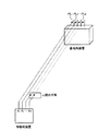
図1に、本発明の送信電力制御が適用される場合の概略図を示す。図1では、複数の送信アンテナ(A1,A2,…,AN)を有する移動局装置が無線局装置と通信を行う場合を示している。複数の送信アンテナを有する移動局装置においては、人体等の影響により各送信アンテナのパスロス測定値(PL1,PL2,…,PLN)に差が生じる。以下に、各送信アンテナのパスロス(PL)のばらつきを考慮して各送信アンテナの送信電力を制御する送信電力制御方法について説明する。 FIG. 1 shows a schematic diagram when the transmission power control of the present invention is applied. FIG. 1 shows a case where a mobile station apparatus having a plurality of transmission antennas (A 1 , A 2 ,..., A N ) communicates with a radio station apparatus. In a mobile station apparatus having a plurality of transmission antennas, there is a difference in path loss measurement values (PL 1 , PL 2 ,..., PL N ) of each transmission antenna due to the influence of the human body and the like. Hereinafter, a transmission power control method for controlling transmission power of each transmission antenna in consideration of variations in path loss (PL) of each transmission antenna will be described.
本発明の第1の側面における送信電力制御方法では、複数の送信アンテナのうち少なくとも一つの送信アンテナのパスロス(PL)を測定するステップと、測定したパスロス(PL)測定値に基づいて代表値パスロス(PL’)を設定するステップと、代表値パスロス(PL’)に基づいて移動局装置の総送信電力(PTX)を決定するステップと、総送信電力(PTX)を各送信アンテナに分配することにより各送信アンテナの送信電力を決定するステップと、を行うことにより各送信アンテナの送信電力を制御する。 In the transmission power control method according to the first aspect of the present invention, a step of measuring a path loss (PL) of at least one transmission antenna among a plurality of transmission antennas, and a representative value path loss based on the measured path loss (PL) measurement value. (PL ′) setting step, the step of determining the total transmission power (P TX ) of the mobile station apparatus based on the representative value path loss (PL ′), and the distribution of the total transmission power (P TX ) to each transmission antenna And determining the transmission power of each transmission antenna, thereby controlling the transmission power of each transmission antenna.
つまり、本発明の第1の側面では、複数の送信アンテナ(A1,A2,…,AN)で測定したパスロス(PL)測定値を、それぞれPL1,PL2,…,PLNとした場合に、PL1,PL2,…,PLNから代表値パスロス(PL’)を設定し、当該PL’に基づいて各送信アンテナの送信電力を制御する。以下に、具体的な手順について説明する。 That is, in the first aspect of the present invention, a plurality of transmission antennas (A 1, A 2, ... , A N) the path loss (PL) measurements taken at each PL 1, PL 2, ..., and PL N In this case, a representative value path loss (PL ′) is set from PL 1 , PL 2 ,..., PL N, and the transmission power of each transmission antenna is controlled based on the PL ′. Hereinafter, a specific procedure will be described.
[パスロス(PL)測定ステップ]
まず、移動局装置に設けられた複数の送信アンテナのパスロス(PL)の測定を行う。パスロス(PL)の測定は、移動局装置に設けられたパスロス測定部において行うことができる。パスロス測定部は、RSRP(Reference Signal Received Power)を測定し、事前に通知される下り参照信号(DL RS)の送信電力(Tx power)とRSRPから送信アンテナのパスロス(PL)を測定する。パスロス(PL)の測定は、複数の送信アンテナ全てに対して行ってもよいし、予め定められた送信アンテナに対して行ってもよい。以下に示す代表値パスロス(PL’)の設定方法に応じて適宜選択することができる。
[Path loss (PL) measurement step]
First, path loss (PL) of a plurality of transmission antennas provided in the mobile station apparatus is measured. The path loss (PL) can be measured in a path loss measuring unit provided in the mobile station apparatus. The path loss measurement unit measures RSRP (Reference Signal Received Power), and measures the transmission power (Tx power) of the downlink reference signal (DL RS) notified in advance and the path loss (PL) of the transmission antenna from RSRP. The path loss (PL) measurement may be performed for all of the plurality of transmission antennas, or may be performed for a predetermined transmission antenna. It can be appropriately selected according to the setting method of the representative value path loss (PL ′) shown below.
[代表値パスロス(PL’)設定ステップ]
測定した送信アンテナのパスロス(PL)測定値に基づいて代表値パスロス(PL’)を設定する。代表値パスロス(PL’)の設定は様々な方法を用いることができ、使用状況等に応じて適宜選択することができる。以下に、代表値パスロス(PL’)の設定方法の具体例として3通りの方法について説明する。
[Representative value path loss (PL ') setting step]
A representative value path loss (PL ′) is set based on the measured path loss (PL) measurement value of the transmitting antenna. Various methods can be used for setting the representative value path loss (PL ′), and the representative value path loss (PL ′) can be appropriately selected in accordance with the use situation or the like. Hereinafter, three methods will be described as specific examples of the representative value path loss (PL ′) setting method.
(PL’設定方法1)
移動局装置に設けられた複数の送信アンテナ(A1,A2,…,AN)で測定したパスロス(PL)測定値をそれぞれ、PL1,PL2,…,PLNとした場合、PL1,PL2,…,PLNを平均化した値を代表値パスロス(PL’)とする(PL’=avg{PL1,PL2,…,PLN})。
(PL 'setting method 1)
A plurality of transmitting antennas provided in the mobile station apparatus (A 1, A 2, ... , A N) each path loss (PL) measurements measured by, PL 1, PL 2, ... , when a PL N, PL A value obtained by averaging 1 , PL 2 ,..., PL N is set as a representative value path loss (PL ′) (PL ′ = avg {PL 1 , PL 2 ,..., PL N }).
この方法によれば、代表値パスロス(PL’)として各送信アンテナのパスロス(PL)測定値の平均的な数値に設定することができる。 According to this method, it is possible to set the average value of the measured path loss (PL) of each transmitting antenna as the representative value path loss (PL ').
(PL’設定方法2)
移動局装置に設けられた複数の送信アンテナ(A1,A2,…,AN)で測定したパスロス(PL)測定値をそれぞれ、PL1,PL2,…,PLNとした場合、PL1,PL2,…,PLNのうち、最もロスが少ない(PL測定値が小さい)値を代表値パスロス(PL’)とする(PL’=min{PL1,PL2,…,PLN})。
(PL 'setting method 2)
A plurality of transmitting antennas provided in the mobile station apparatus (A 1, A 2, ... , A N) each path loss (PL) measurements measured by, PL 1, PL 2, ... , when a PL N, PL 1 , PL 2 ,..., PL N is the representative path loss (PL ′) with the least loss (the PL measurement value is small) (PL ′ = min {PL 1 , PL 2 ,..., PL N }).
この方法によれば、人体等の影響による特定の送信アンテナのパスロス(PL)の増大等を送信電力の決定から排除することが可能となる。 According to this method, an increase in path loss (PL) of a specific transmission antenna due to the influence of a human body or the like can be excluded from determination of transmission power.
(PL’設定方法3)
移動局装置に設けられた複数の送信アンテナ(A1,A2,…,AN)のうち、予め定められた一つの送信アンテナ(Ab)で測定したパスロス(PL)測定値を代表値パスロス(PL’)とする(PL’=PLb)。
(PL 'setting method 3)
Of the plurality of transmission antennas (A 1 , A 2 ,..., A N ) provided in the mobile station apparatus, a path loss (PL) measurement value measured with a predetermined transmission antenna (A b ) is a representative value. Path loss (PL ′) is assumed (PL ′ = PL b ).
この方法によれば、複数の送信アンテナのうち予め定めた送信アンテナ(Ab)のパスロス(PL)を測定すればよいため、パスロス(PL)測定の簡略化を図ることができる。 According to this method, it is only necessary to measure the path loss (PL) of a predetermined transmission antenna (A b ) among a plurality of transmission antennas, and therefore, the path loss (PL) measurement can be simplified.
[総送信電力(PTX)決定ステップ]
上記PL’設定ステップで設定された代表値パスロス(PL’)を用いて移動局装置の総送信電力(PTX)を決定する。具体的には、上述したいずれかのPL’設定方法で設定した代表値パスロス(PL’)に基づいて、移動局装置の総送信電力(PTX)を決定する。総送信電力(PTX)は、以下の式(1)を用いて求めることができる。
[Total Transmit Power (P TX ) Determination Step]
The total transmission power (P TX ) of the mobile station apparatus is determined using the representative value path loss (PL ′) set in the PL ′ setting step. Specifically, the total transmission power (P TX ) of the mobile station apparatus is determined based on the representative value path loss (PL ′) set by any of the PL ′ setting methods described above. The total transmission power (P TX ) can be obtained using the following equation (1).
PTX=min{Pmax,10log10(MPUSCH(i))+P0_PUSCH(j)+α(j)・PL’+ΔTF(i)+f(i)}(dBm)
(1)
P TX = min {P max , 10log 10 (M PUSCH (i)) + P 0 _ PUSCH (j) + α (j) ・ PL '+ Δ TF (i) + f (i)} (dBm)
(1)
ここで、Pmaxは最大送信電力であり、MPUSCHは送信帯域幅であり、P0_PUSCHは目標受信電力であり、αはフラクショナルTPCの重み係数であり、PL’は測定したパスロス(PL)測定値に基づいて設定された代表値パスロス(PL’)であり、ΔTFはMCSに依存するオフセットであり、f(i)はTPCコマンドによる補正値である。 Where P max is the maximum transmission power, M PUSCH is the transmission bandwidth, P 0 _PUSCH is the target reception power, α is the fractional TPC weighting factor, and PL ′ is the measured path loss (PL ) is a set representative value pathloss based on measurements (PL '), Δ TF is the offset that depends on the MCS, f (i) is the correction value according to the TPC command.
Pmax(最大送信電力)は、移動局装置の各送信アンテナの最大値と、全ての送信アンテナの合計での最大値を考慮して決定される。f(i)(TPCコマンドによる補正値)は、送信アンテナ毎に制御方法、又は複数の送信アンテナで共通して制御方法を選択することができる。MPUSCH(送信帯域幅)、P0_PUSCH(目標受信電力)、α(Fractional TPCの重み係数)、ΔTF(MCSに依存するオフセット)は、Rel-8 LTEの場合と同様の数値で設定することができる。また、ΔTF(MCSに依存するオフセット)は0としてもよい。 P max (maximum transmission power) is determined in consideration of the maximum value of each transmission antenna of the mobile station apparatus and the total value of all transmission antennas. As for f (i) (correction value by TPC command), a control method can be selected for each transmission antenna, or a control method can be selected in common for a plurality of transmission antennas. M PUSCH (transmission bandwidth), P 0 _ PUSCH (target received power), α (Fractional TPC weighting factor), Δ TF (offset depending on MCS) are set with the same values as in Rel-8 LTE can do. Further, Δ TF (offset depending on MCS) may be zero.
[各送信アンテナの送信電力(PTXn)決定ステップ]
総送信電力(PTX)決定ステップで決定された総送信電力(PTX)を各送信アンテナに分配することにより、各送信アンテナの送信電力(PTXn)を決定する。各送信アンテナへの総送信電力(PTX)の分配方法は様々な手法を用いることができ、使用状況等に応じて適宜選択することができる。以下に、各送信アンテナの送信電力(PTXn)の決定方法として2通りの方法について説明する。
[Transmission power (P TXn ) determination step for each transmit antenna]
By distributing the total transmit power (P TX) total transmit power determined at decision steps (P TX) to each transmitting antenna determines the transmission power of each transmit antenna (P TXn). Various methods can be used as a method of distributing the total transmission power (P TX ) to each transmission antenna, and can be selected as appropriate according to the usage situation or the like. Hereinafter, two methods will be described as methods for determining the transmission power (P TXn ) of each transmission antenna.
(PTXn決定方法1)
上記式(1)を用いて決定した総送信電力(PTX)を、各送信アンテナに等しく分配する(式(2)参照)。
(P TXn determination method 1)
The total transmission power (P TX ) determined using the above equation (1) is equally distributed to each transmission antenna (see equation (2)).
PTXn=PTX−10log10N(dBm) (2)
式(2)において、Nは送信アンテナ数である。
P TXn = P TX −10log 10 N (dBm) (2)
In Equation (2), N is the number of transmission antennas.
PTXn決定方法1とPL’設定方法1を組み合わせた場合には、PLのばらつきを平均化するという観点から送信電力を制御することができる。また、PTXn決定方法1とPL’設定方法2を組み合わせた場合には、最もロスが少ない(PLが小さい)値を使用するため、人体等の影響による特定の送信アンテナのパスロス(PL)の増大等を送信電力の決定から排除するという観点から送信電力を制御することができる。また、PTXn決定方法1とPL’設定方法3を組み合わせた場合には、任意の送信アンテナのパスロス(PL)を用いるため、パスロス(PL)測定の簡略化を図るという観点から送信電力を制御することができる。
When P TXn determination method 1 and PL ′
(PTXn決定方法2)
上記式(1)を用いて決定した総送信電力(PTX)を、各送信アンテナに利得差Δnに応じて分配する(式(3)参照)。
(P TXn determination method 2)
The total transmission power (P TX ) determined using the above equation (1) is distributed to each transmission antenna according to the gain difference Δ n (see equation (3)).
PTXn=PTX−Δn(dBm) (3) P TXn = P TX −Δ n (dBm) (3)
利得差Δnの制御法としては、移動局装置の送信アンテナ毎に予め設定された値を用いる方法、基地局装置が通知する値(Higher layer signaling、又は、PDCCHにおけるTPCコマンド)を用いる方法等を適用することができる。 The control method of the gain difference delta n, a method of using a preset value for each transmission antenna of the mobile station apparatus, the value the base station apparatus notifies (Higher layer signaling, or, TPC commands in PDCCH) method using such Can be applied.
また、各送信アンテナに利得差Δnに応じて総送信電力(PTX)を分配する場合には、分配後の各送信アンテナの送信電力の合計が所定の数値(Pmax)を超えないようにすることが好ましい。このためには、利得差Δnの合計(線形演算)を1以上にする必要がある。例えば、Δn=10log10(Y/Xn)として、(X1+X2+,…,+XN)≦Yの条件を満たすように設計を行う。 Further, when the total transmission power (P TX ) is distributed to each transmission antenna according to the gain difference Δ n , the total transmission power of each transmission antenna after distribution does not exceed a predetermined numerical value (P max ). It is preferable to make it. For this purpose, it is necessary to sum the gain difference delta n a (linear operation) to 1 or more. For example, the Δ n = 10log 10 (Y / X n), to design so as to satisfy the (X 1 + X 2 +, ..., + X N) ≦ Y conditions.
また、分配後の各送信アンテナの送信電力の合計がPmaxを超える場合には、移動局装置の総送信電力(PTX)をPmaxと設定し、各送信アンテナの送信電力(PTXn’)を以下のとおり決定することができる。 When the total transmission power of each transmission antenna after distribution exceeds P max , the total transmission power (P TX ) of the mobile station apparatus is set to P max and the transmission power (P TXn ′ ) of each transmission antenna is set. ) Can be determined as follows:
・PTXn’決定方法1
PTXn’決定方法1では、分配後の各送信アンテナの送信電力の合計がPmaxを超える場合に、移動局装置の総送信電力(Pmax)を各送信アンテナ等しく再分配する(式(4)参照)。
・ P TXn ' determination method 1
In P TXn ′ determination method 1, when the total transmission power of each transmission antenna after distribution exceeds P max , the total transmission power (P max ) of the mobile station apparatus is redistributed equally to each transmission antenna (formula (4) )reference).
PTXn’=Pmax−10log10N(dBm) (4)
式(4)において、Nは送信アンテナ数である。
P TXn ' = P max -10log 10 N (dBm) (4)
In Expression (4), N is the number of transmission antennas.
この方法を適用することにより、各アンテナに対して上記式(3)で設定される電力から一律に電力を減少して総送信電力(PTX)をPmax以内に再設定する方法と比較して、特性の良い(パスロス(PL)が小さい)アンテナに対してもある程度の送信電力を設定し、当該アンテナを用いた通信を補償することができる。特に、パスロス(PL)が大きいアンテナに相対的に大きい電力を分配しても送信不良が生じる状況では、上記のように送信電力の再設定においてパスロス(PL)の小さいアンテナに対してある程度の送信電力を設定することが有効となる。 By applying this method, compared with the method of reducing the power uniformly from the power set in the above equation (3) for each antenna and resetting the total transmission power (P TX ) within P max. Thus, a certain amount of transmission power can be set even for an antenna with good characteristics (path loss (PL) is small), and communication using the antenna can be compensated. In particular, when transmission failure occurs even when relatively large power is distributed to an antenna with a large path loss (PL), a certain amount of transmission is performed for an antenna with a small path loss (PL) in the resetting of transmission power as described above. Setting power is effective.
・PTXn’決定方法2
PTXn’決定方法2では、分配後の各送信アンテナの送信電力の合計がPmaxを超える場合に、パスロス(PL)の小さいアンテナに対して優先的に送信電力を分配する。具体的には、複数のアンテナの中でパスロス(PL)の小さいアンテナから順に送信電力を割り振る。例えば、移動局装置が第1のアンテナ及び第2のアンテナの2つを具備する場合には、パスロス(PL)の小さいアンテナ(例えば、第1のアンテナ)に対して当該第1のアンテナの最大送信電力(Pmax_1)に達するまで電力を割り振り、残った送信電力を残りの第2のアンテナに割り振る。
・ P TXn ' determination method 2
In P TXn ′ determination method 2, when the total transmission power of each transmission antenna after distribution exceeds P max , transmission power is preferentially distributed to an antenna having a small path loss (PL). Specifically, transmission power is allocated in order from the antenna with the smallest path loss (PL) among the plurality of antennas. For example, when the mobile station apparatus includes two antennas, a first antenna and a second antenna, the maximum of the first antenna with respect to an antenna having a small path loss (PL) (for example, the first antenna). Power is allocated until the transmission power (P max — 1 ) is reached, and the remaining transmission power is allocated to the remaining second antennas.
この方法を適用することにより、上記PTXn’決定方法1と比較して、特性の良い(パスロス(PL)が小さい)アンテナの電力を優先的に補償して、当該アンテナを用いて通信を行う構成とすることができる。このように、特性の悪い(パスロス(PL)が大きい)アンテナに割り振る送信電力を特性の良い(パスロス(PL)が小さい)アンテナに割り振ることにより、移動局装置の通信特性を向上することが可能となる。 By applying this method, the power of an antenna with better characteristics (small path loss (PL)) is preferentially compensated compared to the P TXn ′ determination method 1, and communication is performed using the antenna. It can be configured. In this way, it is possible to improve the communication characteristics of mobile station devices by allocating the transmission power allocated to antennas with poor characteristics (large path loss (PL)) to antennas with good characteristics (low path loss (PL)). It becomes.
・PTXn’決定方法3
PTXn’決定方法3では、分配後の各送信アンテナの送信電力の合計がPmaxを超える場合に、パスロス(PL)の最も小さいアンテナのみ用いて送信を行う。具体的には、パスロス(PL)の最も小さいアンテナに対してのみ電力を設定し、その他のアンテナに対しては送信電力の設定を行わない(送信電力を0とする)。
・ P TXn ' determination method 3
In the P TXn ′ determination method 3, transmission is performed using only the antenna with the smallest path loss (PL) when the total transmission power of each transmission antenna after distribution exceeds P max . Specifically, power is set only for the antenna with the smallest path loss (PL), and transmission power is not set for the other antennas (transmission power is set to 0).
この方法を適用することにより、上記PTXn’決定方法1、2と比較して、特性の悪い(パスロス(PL)が大きい)アンテナに対して送信電力を割り振る工程を省略することができるため、各送信アンテナの送信電力(PTXn)決定ステップの簡略化を図ることが可能となる。また、送信電力の低減を図ることが可能となる。 By applying this method, it is possible to omit the step of allocating transmission power to an antenna having poor characteristics (having a large path loss (PL)) as compared with the P TXn ′ determination methods 1 and 2 above. It becomes possible to simplify the transmission power (P TXn ) determination step of each transmission antenna. In addition, transmission power can be reduced.
・その他のPTXn’決定方法
PTXn’決定方法として、分配後の各送信アンテナの送信電力の合計がPmaxを超えた場合に、各送信アンテナの送信電力(PTXn’)を下記の式(5)を用いて決定してもよい。この方法では、分配後の各送信アンテナの送信電力の合計がPmaxを超えた場合であっても、複数の送信アンテナ間のレベル差を補正するという観点から送信電力の再設定を行うことができる。
・ Other P TXn ' determination methods
As a method for determining P TXn ′, when the total transmission power of each transmission antenna after distribution exceeds P max , the transmission power (P TXn ′ ) of each transmission antenna is determined using the following equation (5). May be. In this method, even if the total transmission power of each transmission antenna after distribution exceeds P max , the transmission power can be reset from the viewpoint of correcting the level difference between multiple transmission antennas. it can.
PTXn’=PTXn−10log10(Pover/N)(dBm) (5)
式(5)において、Nは送信アンテナ数であり、Pover=sum(PTX1,PTX2,…,PTXN)−Pmax(線形演算)である。
P TXn ' = P TXn −10log 10 (P over / N) (dBm) (5)
In Expression (5), N is the number of transmission antennas, and P over = sum (P TX1 , P TX2 ,..., P TXN ) −P max (linear calculation).
PTXn決定方法2と上記PL’設定方法1を組み合わせた場合には、PLのばらつきを平均化し複数の送信アンテナ間のレベル差を補正するという観点から送信電力を制御することができる。また、PTXn決定方法2とPL’設定方法2を組み合わせた場合には、最もロスが少ない(PLが小さい)値を使用するため、人体等の影響による特定の送信アンテナのパスロス(PL)の増大等を送信電力の決定から排除すると共に複数の送信アンテナ間のレベル差を補正するという観点から送信電力を制御することができる。また、PTXn決定方法2とPL’設定方法3を組み合わせた場合には、任意の送信アンテナのパスロス(PL)測定値を用いるため、PL測定の簡略化を図ると共に複数の送信アンテナ間のレベル差を補正するという観点から送信電力を制御することができる。
When the P TXn determination method 2 and the PL ′
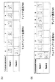
また、PTXn決定方法2において、各送信アンテナの送信電力の合計がPmaxを超えることが想定される場合に、基地局装置から移動局装置に対して、アンテナ選択のPMI(Precoding Matrix Indicator)を通知する構成としてもよい。例えば、送信アンテナ数が2である場合には、図6に示すコードブックを用いることができる。 In addition, in the P TXn determination method 2, when the total transmission power of each transmission antenna is assumed to exceed P max , the antenna selection PMI (Precoding Matrix Indicator) is transmitted from the base station apparatus to the mobile station apparatus. It is good also as a structure which notifies. For example, when the number of transmission antennas is 2, the code book shown in FIG. 6 can be used.
図6(A)は、3GPPで規定されている2送信アンテナのコードブックを示している(3GPP,TR 36.814)。コードブックインデックス4、5がアンテナ選択PMIに相当する。移動局装置が2送信アンテナのうちパスロスを考慮してアンテナ選択PMI(インデックス4又は5)を選択することにより、PLの最も小さいアンテナに対してのみ電力を設定し、その他のアンテナに対しては電力の設定を行わない構成(上記PTXn’決定方法3)とすることができる。
FIG. 6A shows a codebook of two transmitting antennas defined by 3GPP (3GPP, TR 36.814).
なお、図6(A)に示したコードブックにおいては、アンテナ選択PMI(インデックス4、5)において、1/√2により送信電力が半分に制限されているため、選択するアンテナの送信電力を制限しないアンテナ選択PMIを設けたコードブックを用いることが好ましい(図6(B)参照)。この場合、移動局装置が2送信アンテナのうちパスロスを考慮して図6(B)のアンテナ選択PMI(インデックス6又は7)を選択することにより、PLの最も小さいアンテナに対してのみ電力を制限せずに設定し、その他のアンテナに対しては電力の設定を行わない構成とすることができる。
In the code book shown in FIG. 6A, in the antenna selection PMI (
次に、本発明の他の側面に関する送信電力制御方法について説明する。 Next, a transmission power control method according to another aspect of the present invention will be described.
本発明の第2の側面における送信電力制御方法では、複数の送信アンテナのパスロス(PL)をそれぞれ測定するステップと、各送信アンテナで測定したパスロス(PL)測定値に基づいて各送信アンテナの送信電力(PTXn)をそれぞれ決定するステップと、を行うことにより各送信アンテナの送信電力を制御する。 In the transmission power control method according to the second aspect of the present invention, the step of measuring the path loss (PL) of each of the plurality of transmission antennas and the transmission of each transmission antenna based on the measured path loss (PL) value of each transmission antenna. Determining the power (P TXn ), respectively, to control the transmission power of each transmission antenna.
つまり、第2の側面では、複数の送信アンテナ(A1,A2,…,AN)で測定したパスロス(PL)測定値を、それぞれPL1,PL2,…,PLNとした場合に、送信アンテナ毎に測定したPL1,PL2,…,PLNをそれぞれ考慮して、各送信アンテナの送信電力を制御する。以下に、具体的な手順について説明する。 That is, in the second aspect, the plurality of transmission antennas (A 1, A 2, ... , A N) the path loss (PL) measurements taken at each PL 1, PL 2, ..., when a PL N The transmission power of each transmission antenna is controlled in consideration of PL 1 , PL 2 ,..., PL N measured for each transmission antenna. Hereinafter, a specific procedure will be described.
[パスロス(PL)測定ステップ]
まず、移動局装置に設けられた複数の送信アンテナのパスロス(PL)の測定を行う。パスロス(PL)の測定は、移動局装置に設けられたパスロス測定部において行うことができる。パスロス測定部は、RSRP(Reference Signal Received Power)を測定し、事前に通知される下り参照信号(DL RS)の送信電力(Tx power)とRSRPから各送信アンテナのパスロス(PL)を測定する。
[Path loss (PL) measurement step]
First, path loss (PL) of a plurality of transmission antennas provided in the mobile station apparatus is measured. The path loss (PL) can be measured in a path loss measuring unit provided in the mobile station apparatus. The path loss measurement unit measures RSRP (Reference Signal Received Power), and measures the path loss (PL) of each transmission antenna from the transmission power (Tx power) of the downlink reference signal (DL RS) notified in advance and RSRP.
[各送信アンテナの送信電力(PTXn)決定ステップ]
PL値測定ステップで測定した各送信アンテナのPL(=PLn)測定値に基づいて、各送信アンテナの送信電力(PTXn)を決定する。PTXnの決定は様々な方法を用いることができ、使用状況等に応じて適宜選択することができる。以下に、各送信アンテナの送信電力(PTXn)の決定方法として3通りの方法について説明する。
[Transmission power (P TXn ) determination step for each transmit antenna]
Based on the PL (= PL n ) measurement value of each transmission antenna measured in the PL value measurement step, the transmission power (P TXn ) of each transmission antenna is determined. Various methods can be used to determine PTXn , and can be selected as appropriate according to the usage situation. Hereinafter, three methods will be described as methods for determining the transmission power (P TXn ) of each transmission antenna.
(PTXn決定方法1)
各送信アンテナのPL(=PLn)測定値に基づいて、下記の式(6)を用いて各送信アンテナの送信電力(PTXn)を決定する。ここで、最大送信電力は送信アンテナ毎に規定する。
(P TXn determination method 1)
Based on the PL (= PL n ) measurement value of each transmission antenna, the transmission power (P TXn ) of each transmission antenna is determined using the following equation (6). Here, the maximum transmission power is defined for each transmission antenna.
PTXn=min{Pmax_n,10log10(MPUSCH(i))+P0_PUSCH(j)+α(j)・PLn+ΔTF(i)+f(i)−10log10N}(dBm) (6) P TXn = min {P max_n , 10log 10 (M PUSCH (i)) + P 0 _ PUSCH (j) + α (j) ・ PL n + Δ TF (i) + f (i) −10log 10 N} ( dBm) (6)
式(6)において、Pmax_nは送信アンテナ毎の最大送信電力である。 In Expression (6), P max — n is the maximum transmission power for each transmission antenna.
この方法によれば、開ループTPC基準が各送信アンテナのパスロス(PL)であり、受信レベル差をある程度補正できる。また、各送信アンテナを独立した移動局装置のように扱うという観点から送信電力を制御することができる。 According to this method, the open-loop TPC standard is the path loss (PL) of each transmission antenna, and the reception level difference can be corrected to some extent. In addition, transmission power can be controlled from the viewpoint of handling each transmission antenna like an independent mobile station apparatus.
(PTXn決定方法2)
PTXn決定方法2は上記PTXn決定方法1において、移動局装置の最大送信電力を全ての送信アンテナの合計でも規定した方法である。
(P TXn determination method 2)
P TXn determination method 2 is a method in which the maximum transmission power of the mobile station apparatus is defined by the total of all transmission antennas in P TXn determination method 1 described above.
各送信アンテナの送信電力(PTXn)は、上記式(6)を用いて決定する。なお、Pmax_n=Pmaxでもよい。また、各送信アンテナの送信電力の合計がPmaxを超えた場合には、移動局装置の総送信電力(PTX)をPmaxと設定し、各送信アンテナの送信電力(PTXn’)を以下のとおり決定することができる。 The transmission power (P TXn ) of each transmission antenna is determined using the above equation (6). Note that P max_n = P max may be used. When the total transmission power of each transmission antenna exceeds P max , the total transmission power (P TX ) of the mobile station device is set to P max and the transmission power (P TXn ′ ) of each transmission antenna is set. It can be determined as follows.
・PTXn’決定方法1
PTXn’決定方法1では、分配後の各送信アンテナの送信電力の合計がPmaxを超えた場合に、移動局装置の総送信電力(Pmax)を各送信アンテナ等しく分配する(式(7)参照)。
・ P TXn ' determination method 1
In P TXn ′ determination method 1, when the total transmission power of each transmission antenna after distribution exceeds P max , the total transmission power (P max ) of the mobile station apparatus is distributed equally to each transmission antenna (formula (7) )reference).
PTXn’=Pmax−10log10N(dBm) (7)
式(7)において、Nは送信アンテナ数である。
P TXn ' = P max -10log 10 N (dBm) (7)
In Expression (7), N is the number of transmission antennas.
この方法を適用することにより、各アンテナに対して上記式(6)で設定される電力から一律に電力を減少して総送信電力(PTX)をPmax以内に再設定する方法と比較して、特性の良い(パスロス(PL)が小さい)アンテナに対してもある程度の送信電力を設定し、当該アンテナを用いた通信を補償することができる。特に、パスロス(PL)が大きいアンテナに相対的に大きい電力を分配しても送信不良が生じる状況では、上記のように送信電力の再設定においてパスロス(PL)の小さいアンテナに対してある程度の送信電力を設定することが有効となる。 By applying this method, compared with the method of reducing the power uniformly from the power set in the above equation (6) for each antenna and resetting the total transmission power (P TX ) within P max. Thus, a certain amount of transmission power can be set even for an antenna with good characteristics (path loss (PL) is small), and communication using the antenna can be compensated. In particular, when transmission failure occurs even when relatively large power is distributed to an antenna with a large path loss (PL), a certain amount of transmission is performed for an antenna with a small path loss (PL) in the resetting of transmission power as described above. Setting power is effective.
・PTXn’決定方法2
PTXn’決定方法2では、分配後の各送信アンテナの送信電力の合計がPmaxを超える場合に、パスロス(PL)の小さいアンテナに対して優先的に送信電力を分配する。具体的には、複数のアンテナの中でパスロス(PL)の小さいアンテナから順に送信電力を割り振る。例えば、移動局装置が第1のアンテナ及び第2のアンテナの2つを具備する場合には、パスロス(PL)の小さいアンテナ(例えば、第1のアンテナ)に対して当該第1のアンテナの最大送信電力(Pmax_1)に達するまで電力を割り振り、残った送信電力を残りの第2のアンテナに割り振る。
・ P TXn ' determination method 2
In P TXn ′ determination method 2, when the total transmission power of each transmission antenna after distribution exceeds P max , transmission power is preferentially distributed to an antenna having a small path loss (PL). Specifically, transmission power is allocated in order from the antenna with the smallest path loss (PL) among the plurality of antennas. For example, when the mobile station apparatus includes two antennas, a first antenna and a second antenna, the maximum of the first antenna with respect to an antenna having a small path loss (PL) (for example, the first antenna). Power is allocated until the transmission power (P max — 1 ) is reached, and the remaining transmission power is allocated to the remaining second antennas.
この方法を適用することにより、上記PTXn’決定方法1と比較して、特性の良い(パスロス(PL)が小さい)アンテナの電力を優先的に補償して、当該アンテナを用いて通信を行う構成とすることができる。このように、特性の悪い(パスロス(PL)が大きい)アンテナに割り振る送信電力を特性の良い(パスロス(PL)が小さい)アンテナに割り振ることにより、移動局装置の通信特性を向上することが可能となる。 By applying this method, the power of an antenna with better characteristics (small path loss (PL)) is preferentially compensated compared to the P TXn ′ determination method 1, and communication is performed using the antenna. It can be configured. In this way, it is possible to improve the communication characteristics of mobile station devices by allocating the transmission power allocated to antennas with poor characteristics (large path loss (PL)) to antennas with good characteristics (low path loss (PL)). It becomes.
・PTXn’決定方法3
PTXn’決定方法3では、分配後の各送信アンテナの送信電力の合計がPmaxを超える場合に、パスロス(PL)の最も小さいアンテナのみ用いて送信を行う。具体的には、パスロス(PL)の最も小さいアンテナに対してのみ電力を設定し、その他のアンテナに対しては送信電力の設定を行わない(送信電力を0とする)。
・ P TXn ' determination method 3
In the P TXn ′ determination method 3, transmission is performed using only the antenna with the smallest path loss (PL) when the total transmission power of each transmission antenna after distribution exceeds P max . Specifically, power is set only for the antenna with the smallest path loss (PL), and transmission power is not set for the other antennas (transmission power is set to 0).
この方法を適用することにより、上記PTXn’決定方法1、2と比較して、特性の悪い(パスロス(PL)が大きい)アンテナに対して送信電力を割り振る工程を省略することができるため、各送信アンテナの送信電力(PTXn)決定ステップの簡略化を図ることが可能となる。また、送信電力の低減を図ることが可能となる。 By applying this method, it is possible to omit the step of allocating transmission power to an antenna having poor characteristics (having a large path loss (PL)) as compared with the P TXn ′ determination methods 1 and 2 above. It becomes possible to simplify the transmission power (P TXn ) determination step of each transmission antenna. In addition, transmission power can be reduced.
・その他のPTXn’決定方法
PTXn’決定方法として、分配後の各送信アンテナの送信電力の合計がPmaxを超えた場合に、各送信アンテナの送信電力(PTXn’)を下記の式(8)を用いて決定してもよい。この方法では、分配後の各送信アンテナの送信電力の合計がPmaxを超えた場合であっても、複数の送信アンテナ間のレベル差を補正するという観点から送信電力の再設定を行うことができる。
・ Other P TXn ' determination methods
As a method for determining P TXn ′, when the total transmission power of each transmission antenna after distribution exceeds P max , the transmission power (P TXn ′ ) of each transmission antenna is determined using the following equation (8). May be. In this method, even if the total transmission power of each transmission antenna after distribution exceeds P max , the transmission power can be reset from the viewpoint of correcting the level difference between multiple transmission antennas. it can.
PTXn’=PTXn−10log10(Pover/N)(dBm) (8)
式(8)において、Nは送信アンテナ数であり、Pover=sum(PTX1,PTX2,…,PTXN)−Pmax(線形演算)である。
P TXn ' = P TXn −10log 10 (P over / N) (dBm) (8)
In Expression (8), N is the number of transmission antennas, and P over = sum (P TX1 , P TX2 ,..., P TXN ) −P max (linear calculation).
また、本発明の第2の側面における送信電力制御方法のPTXn決定方法2においても、各送信アンテナの送信電力の合計がPmaxを超えることが想定される場合に、基地局装置から移動局装置に対して、アンテナ選択のPMI(Precoding Matrix Indicator)を通知する構成(上記図6)とすることができる。 Also in the P TXn determination method 2 of the transmission power control method according to the second aspect of the present invention, when the total transmission power of each transmission antenna is assumed to exceed P max , the base station apparatus moves to the mobile station. The apparatus can be configured to notify the apparatus of PMI (Precoding Matrix Indicator) for antenna selection (FIG. 6 above).
(PTXn決定方法3)
測定した送信アンテナのパスロス(PL)測定値に基づいて代表値パスロス(PL’)を設定し、各送信アンテナの送信電力(PTXn)を代表値パスロス(PL’)とのパスロス差(PLn−PL’)に基づいて補正して、各送信アンテナの送信電力(PTXn)を決定する。
(P TXn determination method 3)
Based on the measured path loss (PL) measurement value of the transmission antenna, the representative value path loss (PL ′) is set, and the transmission power (P TXn ) of each transmission antenna is set to the path loss difference (PL n ) from the representative value path loss (PL ′). -Correct based on PL ') and determine the transmit power ( PTXn ) of each transmit antenna.
代表値パスロス(PL’)の決定は、上記第1の側面における送信電力制御方法で示した3通りのPL’設定方法のいずれかを用いて決定することができる。そして、決定した代表値パスロス(PL’)に基づいて、以下の式(9)及び(10)により各送信アンテナの送信電力(PTXn)を決定する。 The representative value path loss (PL ′) can be determined using any one of the three PL ′ setting methods shown in the transmission power control method in the first aspect. Then, based on the determined representative value path loss (PL ′), the transmission power (P TXn ) of each transmission antenna is determined by the following equations (9) and (10).
PTXb=min{Pmax_n,10log10(MPUSCH(i))+P0_PUSCH(j)+α(j)・PLb+ΔTF(i)+f(i)−10log10N}(dBm) (9)
PTXn=PTXb+β(PLn−PL’) (10)
P TXb = min {P max_n , 10log 10 (M PUSCH (i)) + P 0 _ PUSCH (j) + α (j) ・ PL b + Δ TF (i) + f (i) −10log 10 N} ( dBm) (9)
P TXn = P TXb + β (PL n −PL ′) (10)
ここで、βは重み係数であり、β=1である場合には、各送信アンテナの平均受信電力が等しくなるように制御される。 Here, β is a weighting coefficient. When β = 1, the average received power of each transmitting antenna is controlled to be equal.
また、全ての送信アンテナの送信電力の合計がPmaxを超えた場合には、上記PTXn決定方法2と同様の方法(式(7)又は式(8))により移動局装置の総送信電力をPmaxに抑えればよい。
When the total transmission power of all the transmission antennas exceeds P max , the total transmission power of the mobile station apparatus is obtained by the same method (Equation (7) or Equation (8)) as PTXn
この方法によれば、複数の送信アンテナ間のレベル差を高い精度で補正するという観点から送信電力を制御することができる。 According to this method, transmission power can be controlled from the viewpoint of correcting a level difference between a plurality of transmission antennas with high accuracy.
以下に、本発明の第1の側面又は第2の側面で示した送信電力制御法を適用した場合の移動局装置及び基地局装置等の構成について説明する。 Hereinafter, configurations of a mobile station device, a base station device, and the like when the transmission power control method shown in the first aspect or the second aspect of the present invention is applied will be described.
図2を参照して、移動局装置の機能構成について説明する。図2は、本発明の実施の形態に係る移動局装置の機能ブロック図である。 A functional configuration of the mobile station apparatus will be described with reference to FIG. FIG. 2 is a functional block diagram of the mobile station apparatus according to the embodiment of the present invention.
図2に示すように、移動局装置100nは、複数の送受信アンテナ1021〜102Nと、複数の送受信アンテナ1021〜102Nに対応したアンプ部104と、送受信部106と、ベースバンド信号処理部108と、呼処理部110と、アプリケーション部112とを備えて構成されている。
As shown in FIG. 2, the mobile station apparatus 100 n includes a plurality of transmit and receive
上りリンクのデータについては、アプリケーション部112からベースバンド信号処理部108に入力される。ベースバンド信号処理部108では、再送制御(H-ARQ(Hybrid ARQ))の処理、スケジューリング、伝送フォーマット選択、チャネル符号化、送信電力設定などがなされて、アンテナ毎に送受信部106に転送される。送受信部106では、ベースバンド信号処理部108から出力されたベースバンド信号をアンテナ毎に無線周波数信号へ周波数変換する。周波数変換された信号は、その後、アンプ部104で増幅されて送受信アンテナ1021〜102N毎に送信される。
Uplink data is input from the
下りリンクのデータについては、送受信アンテナ1021〜102Nで受信した無線周波数信号がアンプ部104において、AGC(Auto Gain Control)の下で受信電力が一定電力に補正されるように増幅される。増幅された無線周波数信号は、送受信部106においてベースバンド信号へ周波数変換される。このベースバンド信号は、ベースバンド信号処理部108で所定の処理(誤り訂正、複合など)がなされた後、呼処理部110及びアプリケーション部112に転送される。
For the downlink data, the radio frequency signal received by the transmitting and receiving antennas 102 1 to 102 N is amplified by the
呼処理部110は、基地局装置との通信の管理等を行い、アプリケーション部112は、物理レイヤやMACレイヤより上位のレイヤに関する処理等を行う。
The
次に、図3を参照して、移動局装置のベースバンド処理部の機能構成について説明する。図3は、移動局装置のベースバンド信号処理部の機能ブロック図である。 Next, the functional configuration of the baseband processing unit of the mobile station apparatus will be described with reference to FIG. FIG. 3 is a functional block diagram of the baseband signal processing unit of the mobile station apparatus.
ベースバンド信号処理部108は、レイヤ1処理部1081と、MAC処理部1082と、RLC処理部1083と、PL測定部1084と、送信電力設定部1085とを有している。
The baseband
レイヤ1処理部1081は、主に物理レイヤに関する処理をする。レイヤ1処理部1081では、例えば、下りリンクで受信した信号に対して、チャネル復号化、離散フーリエ変換(DFT)周波数デマッピング、逆フーリエ変換(IFFT)、データ復調等の処理が行われる。また、上りリンクで送信する信号に対して、チャネル符号化、データ変調、周波数マッピング、逆フーリエ変換(IFFT)等の処理を行う。
The
MAC処理部1082は、下りリンクで受信した信号に対するMACレイヤでの再送制御(HARQ)、下りリンクに対するスケジューリング情報の解析(PDSCHの伝送フォーマットの特定、PDSCHのリソースブロックの特定)等を行う。また、MAC処理部1082は、上りリンクで送信する信号に対するMAC再送制御、上りスケジューリング情報の解析(PUSCHの伝送フォーマットの特定、PUSCHのリソースブロックの特定等の処理)等を行う。
The
RLC処理部1083は、上りリンクで受信したパケット、およびアプリケーション部112から受け取る下りリンクで送信するパケットに対して、パケットの分割、パケットの結合、RLCレイヤでの再送制御等をする。
The
PL測定部1084は、RSRP(Reference Signal Received Power)を測定し、事前に通知される下り参照信号(DL RS)の送信電力(Tx power)とRSRPから各アンテナのパスロス(PL)を測定する。
The
送信電力設定部1085は、PL測定部1084で測定したパスロス(PL)測定値に基づいて、各アンテナの送信電力制御に使用する代表値パスロス(PL’)又は各アンテナの送信電力制御に使用するパスロス(PL)測定値を設定し、各アンテナの送信電力を設定する。送信電力制御に使用する代表値パスロス(PL’)の設定及び各アンテナの送信電力の設定は、上記本発明の第1の側面又は第2の側面で示した方法を用いることができる。また、分配後の各送信アンテナの送信電力の合計がPmaxを超える場合には、移動局装置の総送信電力(PTX)をPmaxと設定し、各送信アンテナの送信電力(PTXn’)をPTXn’決定方法1〜3等を用いて設定する。PTXn’決定方法3を適用する場合には、移動局装置が上記図6に示したコードブックからアンテナ選択PMIを選択する構成とすることができる。
Based on the path loss (PL) measurement value measured by the
送信電力設定部1085において、本発明の第1の側面における送信電力制御方法を適用する場合には、送信電力設定部1085が、測定したパスロス(PL)測定値に基づいて代表値パスロス(PL’)を設定するステップと、代表値パスロス(PL’)に基づいて移動局装置の総送信電力(PTX)を決定するステップと、総送信電力(PTX)を各送信アンテナに分配することにより各送信アンテナの送信電力を決定するステップとを行う。例えば、PL測定部1084で測定された各送信アンテナのパスロス測定値のうち、最もPL測定値が小さい値を代表値パスロス(PL’)と設定して上記式(1)を用いて総送信電力(PTX)を決定した後、各送信アンテナに総送信電力(PTX)を等しく分配する。この場合、上記第1の側面におけるPL’設定方法2とPTXn決定方法1を適用しているが、これに限られず他のPL’設定方法、PTXn決定方法を適用してもよい。
When the transmission
送信電力設定部1085において、本発明の第2の側面における送信電力制御方法を適用する場合には、送信電力設定部1085が、各送信アンテナで測定したパスロス(PL)測定値に基づいてそれぞれ各送信アンテナの送信電力(PTXn)を決定するステップを行う。例えば、PL測定部1084で測定された各送信アンテナのPL(=PLn)測定値に基づいて、上記式(6)を用いて各送信アンテナの送信電力(PTXn)を決定する。この場合、上記第2の側面におけるPTXn決定方法1を適用しているがこれに限られず他のPTXn決定方法を適用してもよい。
In the transmission
次に、図4を参照して、基地局装置の機能構成について説明する。図4は、本発明の実施の形態に係る基地局装置の機能ブロック図である。 Next, the functional configuration of the base station apparatus will be described with reference to FIG. FIG. 4 is a functional block diagram of the base station apparatus according to the embodiment of the present invention.
図4に示すように、基地局装置200は、複数の送受信アンテナ202(1つのみ図示)と、アンプ部204と、送受信部206と、ベースバンド信号処理部208と、呼処理部210と、伝送路インターフェース212とを備えて構成されている。
As shown in FIG. 4, the base station apparatus 200 includes a plurality of transmission / reception antennas 202 (only one is shown), an
上りリンクのデータについては、送受信アンテナ202で受信された無線周波数信号がアンプ部204において、AGCの下で受信電力が一定電力に補正されるように増幅される。増幅された無線周波数信号は、送受信部206においてベースバンド信号へ周波数変換される。このベースバンド信号は、ベースバンド信号処理部208で所定の処理(誤り訂正、複合など)がなされた後、伝送路インターフェース212を介して図示しないアクセスゲートウェイ装置に転送される。アクセスゲートウェイ装置は、コアネットワークに接続されており、各移動局を管理している。
For the uplink data, the radio frequency signal received by the transmission / reception antenna 202 is amplified by the
下りリンクのデータについては、上位装置から伝送路インターフェース212を介してベースバンド信号処理部208に入力される。ベースバンド信号処理部208では、再送制御(H-ARQ(Hybrid ARQ))の処理、スケジューリング、伝送フォーマット選択、チャネル符号化等がなされて送受信部206に転送される。送受信部206では、ベースバンド信号処理部208から出力されたベースバンド信号を無線周波数信号へ周波数変換する。周波数変換された信号は、その後、アンプ部204で増幅されて送受信アンテナ202から送信される。
Downlink data is input from the host device to the baseband
呼処理部210は、上位装置の無線制御局との間で呼処理制御信号を送受信し、基地局装置200の状態管理やリソース割り当てをする。なお、レイヤ1処理部2081とMAC処理部2082における処理は、呼処理部210において設定されている、基地局装置200と移動局装置100nとの間の通信状態に基づいてなされる。
The
次に、図5を参照して、ベースバンド処理部の機能構成について説明する。図5は、基地局装置のベースバンド信号処理部の機能ブロック図である。 Next, the functional configuration of the baseband processing unit will be described with reference to FIG. FIG. 5 is a functional block diagram of the baseband signal processing unit of the base station apparatus.
図5に示すように、ベースバンド信号処理部208は、レイヤ1処理部2081と、MAC(Medium Access Control)処理部2082と、RLC処理部2083と、送信電力制御部2084とを有している。
As illustrated in FIG. 5, the baseband
レイヤ1処理部2081は、主に物理レイヤに関する処理を行う。レイヤ1処理部2081では、例えば、上りリンクで受信した信号に対して、チャネル復号化、離散フーリエ変換(DFT)、周波数デマッピング、逆フーリエ変換(IFFT)、データ復調等の処理が行われる。また、下りリンクで送信する信号に対して、チャネル符号化、データ変調、周波数マッピング、逆フーリエ変換(IFFT)等の処理を行う。
The
MAC処理部2082は、上りリンクで受信した信号に対するMACレイヤでの再送制御(HARQ)、上り/下りリンクに対するスケジューリング、PUSCH/PDSCHの伝送フォーマットの選択、PUSCH/PDSCHのリソースブロックの選択等の処理を行う。
The
RLC処理部2083は、上りリンクで受信したパケット/下りリンクで送信するパケットに対して、パケットの分割、パケットの結合、RLCレイヤでの再送制御等を行う。
The
送信電力制御部2084は、移動局装置の送信電力情報を管理し、TPCコマンドの設定、通知を行う。また、移動局装置の各送信アンテナの利得差を考慮し、Higher layer signaling又はPDCCHにおけるTPCコマンドにて移動局装置に通知を行う。なお、TPCコマンドによる補正値(f(i))は、移動局装置において、送信アンテナ毎、又は複数の送信アンテナで共通して制御される。また、分配後の各送信アンテナの送信電力の合計がPmaxを超えることが想定される場合には、移動局装置に対して、アンテナ選択のPMIを通知してもよい。
The transmission
以上のように、本実施の形態に係る送信電力制御方法によれば、移動局装置が複数の送信アンテナを具備する場合であっても、各送信アンテナのパスロス(PL)を考慮して送信電力を制御することにより、上りリンクの送信電力を適切に制御することができる。 As described above, according to the transmission power control method according to the present embodiment, even when the mobile station apparatus includes a plurality of transmission antennas, the transmission power is considered in consideration of the path loss (PL) of each transmission antenna. By controlling this, it is possible to appropriately control uplink transmission power.
また、今回開示された実施の形態は、全ての点で例示であってこの実施の形態に制限されるものではない。本発明の範囲は、上記した実施の形態のみの説明ではなくて特許請求の範囲によって示され、特許請求の範囲と均等の意味および範囲内での全ての変更が含まれることが意図される。 The embodiment disclosed this time is illustrative in all respects and is not limited to this embodiment. The scope of the present invention is shown not by the above description of the embodiments but by the scope of the claims, and is intended to include all modifications within the meaning and scope equivalent to the scope of the claims.
以上説明したように、本発明は、複数の送信アンテナを有する移動局装置の送信電力を適切に制御できるという効果を有し、特に上りリンクの送信電力を制御する送信電力制御方法、基地局装置および移動局装置に有用である。 As described above, the present invention has an effect that the transmission power of a mobile station apparatus having a plurality of transmission antennas can be appropriately controlled, and in particular, a transmission power control method for controlling uplink transmission power, and a base station apparatus And useful for mobile station devices.
100n 移動局装置
1021 送受信アンテナ
102N 送受信アンテナ
104 アンプ部
106 送受信部
108 ベースバンド信号処理部
110 呼処理部
112 アプリケーション部
1081 レイヤ1処理部
1082 MAC処理部
1083 RLC処理部
1084 パスロス(PL)測定部
1085 送信電力設定部
200 基地局装置
202 送受信アンテナ
204 アンプ部
206 送受信部
208 ベースバンド信号処理部
210 呼処理部
212 伝送路インターフェース
2081 レイヤ1処理部
2082 MAC処理部
2083 RLC処理部
2084 送信電力制御部
100 n mobile station apparatus 102 1 transmission / reception antenna 102 N transmission /
Claims (8)
前記複数の送信アンテナのパスロス(PL)を測定するステップと、
測定した複数のパスロス(PL)測定値に基づいて代表値パスロス(PL’)を設定するステップと、
前記代表値パスロス(PL’)に基づいて前記移動局装置の総送信電力(PTX)を決定するステップと、
前記総送信電力(PTX)を前記複数の送信アンテナに分配することにより各送信アンテナの送信電力(PTXn)を決定するステップと、を有し、
前記総送信電力(PTX)が以下の式(1)で求められ、前記総送信電力(PTX)を前記複数の送信アンテナにそれぞれ均等に分配することを特徴とする送信電力制御方法。
式(1)
PTX=min{Pmax,10log10(MPUSCH(i))+P0_PUSCH(j)+α(j)・PL’+ΔTF(i)+f(i)}(dBm)
ここで、Pmaxは最大送信電力であり、MPUSCHは送信帯域幅であり、P0_PUSCHは目標受信電力であり、αはフラクショナルTPCの重み係数であり、PL’は測定したパスロス(PL)測定値に基づいて設定された代表値パスロス(PL’)であり、ΔTFはMCSに依存するオフセットであり、f(i)はTPCコマンドによる補正値である。 A transmission power control method for controlling uplink transmission power of a mobile station apparatus having a plurality of transmission antennas,
Measuring the path Sloss (PL) of the plurality of transmitting antennas,
Setting a representative value path loss (PL ′) based on a plurality of measured path loss (PL) measurements;
Determining a total transmission power (P TX ) of the mobile station device based on the representative value path loss (PL ′);
Determining the transmission power (P TXn ) of each transmission antenna by distributing the total transmission power (P TX ) to the plurality of transmission antennas,
The total transmit power (P TX) is determined by Equation (1) below, transmission power control method characterized by evenly distributing each of the total transmission power (P TX) to the plurality of transmitting antennas.
Formula (1)
P TX = min {P max , 10log 10 (M PUSCH (i)) + P 0 _ PUSCH (j) + α (j) ・ PL '+ Δ TF (i) + f (i)} (dBm)
Where P max is the maximum transmission power, M PUSCH is the transmission bandwidth, P 0 _PUSCH is the target reception power, α is the weighting factor of the fractional TPC, and PL ′ is the measured path loss (PL ) is a set representative value pathloss based on measurements (PL '), Δ TF is the offset that depends on the MCS, f (i) is the correction value according to the TPC command.
前記送信電力設定部は、前記パスロス測定部で測定されたパスロス(PL)測定値に基づいて代表値パスロス(PL’)を設定し、前記代表値パスロス(PL’)に基づいて前記移動局装置の総送信電力(PTX)を決定し、前記総送信電力(PTX)を前記複数の送信アンテナに分配することにより前記各送信アンテナの送信電力(PTXn)を決定し、
前記総送信電力(PTX)が以下の式(1)で求められ、前記総送信電力(PTX)を前記複数の送信アンテナにそれぞれ均等に分配することを特徴とする移動局装置。
式(1)
PTX=min{Pmax,10log10(MPUSCH(i))+P0_PUSCH(j)+α(j)・PL’+ΔTF(i)+f(i)}(dBm)
ここで、Pmaxは最大送信電力であり、MPUSCHは送信帯域幅であり、P0_PUSCHは目標受信電力であり、αはフラクショナルTPCの重み係数であり、PL’は測定したパスロス(PL)測定値に基づいて決定された代表値パスロス(PL’)であり、ΔTFはMCSに依存するオフセットであり、f(i)はTPCコマンドによる補正値である。 A plurality of transmission antennas, a path loss measurement unit that measures path loss (PL) of the plurality of transmission antennas, and a transmission power (P TXn ) of each transmission antenna is determined based on the measured plurality of path loss (PL) measurements. A mobile station apparatus comprising a transmission power setting unit,
The transmission power setting unit sets a representative value path loss (PL ′) based on a path loss (PL) measurement value measured by the path loss measuring unit, and the mobile station apparatus based on the representative value path loss (PL ′) total transmission determines the power (P TX), wherein to determine the transmission power of each transmit antenna (P TXn) by distributing the total transmit power (P TX) to the plurality of transmitting antennas,
The total transmission power (P TX ) is obtained by the following equation (1), and the total transmission power (P TX ) is equally distributed to each of the plurality of transmission antennas.
Formula (1)
P TX = min {P max , 10log 10 (M PUSCH (i)) + P 0 _ PUSCH (j) + α (j) ・ PL '+ Δ TF (i) + f (i)} (dBm)
Where P max is the maximum transmission power, M PUSCH is the transmission bandwidth, P 0 _PUSCH is the target reception power, α is the weighting factor of the fractional TPC, and PL ′ is the measured path loss (PL ) is determined on the basis of measured values representative value path loss (PL '), Δ TF is the offset that depends on the MCS, f (i) is the correction value according to the TPC command.
Priority Applications (7)
| Application Number | Priority Date | Filing Date | Title |
|---|---|---|---|
| JP2010181813A JP5149348B2 (en) | 2010-04-05 | 2010-08-16 | Transmission power control method and mobile station apparatus |
| CN201180027783.7A CN102948226B (en) | 2010-04-05 | 2011-04-05 | Transmitted power control method and mobile station apparatus |
| KR1020127026872A KR20130024898A (en) | 2010-04-05 | 2011-04-05 | Power transmission control method and mobile station device |
| US13/261,461 US8929232B2 (en) | 2010-04-05 | 2011-04-05 | Transmission power control method and mobile station apparatus |
| EP11765893.0A EP2557864A4 (en) | 2010-04-05 | 2011-04-05 | Power transmission control method and mobile station device |
| PCT/JP2011/058570 WO2011125993A1 (en) | 2010-04-05 | 2011-04-05 | Power transmission control method and mobile station device |
| MX2012011499A MX2012011499A (en) | 2010-04-05 | 2011-04-05 | Power transmission control method and mobile station device. |
Applications Claiming Priority (3)
| Application Number | Priority Date | Filing Date | Title |
|---|---|---|---|
| JP2010087384 | 2010-04-05 | ||
| JP2010087384 | 2010-04-05 | ||
| JP2010181813A JP5149348B2 (en) | 2010-04-05 | 2010-08-16 | Transmission power control method and mobile station apparatus |
Publications (3)
| Publication Number | Publication Date |
|---|---|
| JP2011234334A JP2011234334A (en) | 2011-11-17 |
| JP2011234334A5 JP2011234334A5 (en) | 2012-04-12 |
| JP5149348B2 true JP5149348B2 (en) | 2013-02-20 |
Family
ID=44762929
Family Applications (1)
| Application Number | Title | Priority Date | Filing Date |
|---|---|---|---|
| JP2010181813A Active JP5149348B2 (en) | 2010-04-05 | 2010-08-16 | Transmission power control method and mobile station apparatus |
Country Status (7)
| Country | Link |
|---|---|
| US (1) | US8929232B2 (en) |
| EP (1) | EP2557864A4 (en) |
| JP (1) | JP5149348B2 (en) |
| KR (1) | KR20130024898A (en) |
| CN (1) | CN102948226B (en) |
| MX (1) | MX2012011499A (en) |
| WO (1) | WO2011125993A1 (en) |
Families Citing this family (18)
| Publication number | Priority date | Publication date | Assignee | Title |
|---|---|---|---|---|
| CN105827292A (en) * | 2010-04-09 | 2016-08-03 | 交互数字专利控股公司 | Method for configuring transmission parameters for uplink (UL) transmissions utilizing multiple antennas and WRTU |
| ES2948057T3 (en) * | 2011-05-02 | 2023-08-30 | Blackberry Ltd | Methods and system of wireless communication with remote radio heads |
| CN104471999B (en) * | 2012-08-17 | 2018-12-14 | 华为技术有限公司 | The sending method and device of ascending control information |
| CN103634889B (en) * | 2012-08-21 | 2016-12-07 | 中国移动通信集团设计院有限公司 | Transmission power adjustment method and device |
| KR102008467B1 (en) * | 2012-12-27 | 2019-08-07 | 삼성전자주식회사 | Uplink power control method and apparatus in a beamforming based wireless communication system |
| EP2787662B1 (en) * | 2013-04-05 | 2018-02-28 | Telefonaktiebolaget LM Ericsson (publ) | Antenna port detection |
| US20170289920A1 (en) * | 2016-03-29 | 2017-10-05 | Futurewei Technologies, Inc. | Method and Apparatus for Resource and Power Allocation in Non-Orthogonal Uplink Transmissions |
| US10367677B2 (en) * | 2016-05-13 | 2019-07-30 | Telefonaktiebolaget Lm Ericsson (Publ) | Network architecture, methods, and devices for a wireless communications network |
| US10630410B2 (en) | 2016-05-13 | 2020-04-21 | Telefonaktiebolaget Lm Ericsson (Publ) | Network architecture, methods, and devices for a wireless communications network |
| JP6994304B2 (en) * | 2017-03-02 | 2022-01-14 | 株式会社Nttドコモ | Wireless terminals, transmission power control methods, and wireless base stations |
| KR102439792B1 (en) * | 2018-02-14 | 2022-09-02 | 삼성전자주식회사 | Apparatus and method for determining transmission power in wireless communication system |
| CN110475330B (en) * | 2018-05-11 | 2021-05-25 | 电信科学技术研究院有限公司 | Uplink power control method, terminal and network equipment |
| US20200145929A1 (en) * | 2018-11-01 | 2020-05-07 | Qualcomm Incorporated | Power control for multi-panel transmission |
| CN112740767B (en) * | 2018-12-20 | 2023-02-28 | Oppo广东移动通信有限公司 | Method for determining transmitting power of antenna, terminal equipment and network equipment |
| WO2020132862A1 (en) * | 2018-12-25 | 2020-07-02 | Oppo广东移动通信有限公司 | Method for controlling uplink transmission power, terminal device, and network device |
| CN112398622B (en) * | 2019-08-16 | 2022-05-20 | 大唐移动通信设备有限公司 | Uplink sending method, terminal and network side equipment |
| CN111212482B (en) * | 2020-01-13 | 2022-05-24 | 普联技术有限公司 | Wireless communication control method, device, equipment and computer readable storage medium |
| CN112929105B (en) * | 2021-01-22 | 2022-05-13 | 中国铁塔股份有限公司 | Signal source distance determining method and device and electronic equipment |
Family Cites Families (7)
| Publication number | Priority date | Publication date | Assignee | Title |
|---|---|---|---|---|
| JP2000040988A (en) * | 1998-07-23 | 2000-02-08 | Sony Corp | Radio communication equipment |
| JP3848068B2 (en) * | 2000-09-12 | 2006-11-22 | 株式会社エヌ・ティ・ティ・ドコモ | CDMA radio transmission apparatus, CDMA radio transmission / reception system, transmission power control method for CDMA radio transmission apparatus, and transmission power control method for radio transmission apparatus in CDMA radio transmission / reception system |
| JP2008258937A (en) * | 2007-04-05 | 2008-10-23 | Matsushita Electric Ind Co Ltd | Propagation environment estimation method, apparatus and communication method |
| JP5147123B2 (en) * | 2008-08-05 | 2013-02-20 | シャープ株式会社 | Wireless communication system, base station apparatus, mobile station apparatus, and wireless communication method |
| JP5084044B2 (en) * | 2008-08-05 | 2012-11-28 | シャープ株式会社 | Wireless communication system, mobile station apparatus, and wireless communication method |
| US8583160B2 (en) * | 2009-05-04 | 2013-11-12 | Qualcomm Incorporated | Uplink power control for wireless communication |
| US9144040B2 (en) * | 2010-04-01 | 2015-09-22 | Futurewei Technologies, Inc. | System and method for uplink multi-antenna power control in a communications system |
-
2010
- 2010-08-16 JP JP2010181813A patent/JP5149348B2/en active Active
-
2011
- 2011-04-05 US US13/261,461 patent/US8929232B2/en not_active Expired - Fee Related
- 2011-04-05 MX MX2012011499A patent/MX2012011499A/en active IP Right Grant
- 2011-04-05 CN CN201180027783.7A patent/CN102948226B/en not_active Expired - Fee Related
- 2011-04-05 EP EP11765893.0A patent/EP2557864A4/en not_active Withdrawn
- 2011-04-05 WO PCT/JP2011/058570 patent/WO2011125993A1/en active Application Filing
- 2011-04-05 KR KR1020127026872A patent/KR20130024898A/en not_active Application Discontinuation
Also Published As
| Publication number | Publication date |
|---|---|
| US20130100828A1 (en) | 2013-04-25 |
| CN102948226A (en) | 2013-02-27 |
| KR20130024898A (en) | 2013-03-08 |
| US8929232B2 (en) | 2015-01-06 |
| WO2011125993A1 (en) | 2011-10-13 |
| JP2011234334A (en) | 2011-11-17 |
| CN102948226B (en) | 2016-03-23 |
| EP2557864A4 (en) | 2013-12-04 |
| MX2012011499A (en) | 2012-12-17 |
| EP2557864A1 (en) | 2013-02-13 |
Similar Documents
| Publication | Publication Date | Title |
|---|---|---|
| JP5149348B2 (en) | Transmission power control method and mobile station apparatus | |
| US10313984B2 (en) | User terminal and radio communication method | |
| KR102269476B1 (en) | System and method for wireless power control | |
| CN111386734B (en) | Communication method, communication device and system | |
| US9894618B2 (en) | Wireless device for controlling transmission power | |
| KR101750369B1 (en) | Apparatus and method for controlling uplink power in mobile communication system with distributed antennas | |
| JP5588236B2 (en) | Transmission power control method, mobile terminal apparatus and radio base station apparatus | |
| WO2011083797A1 (en) | Mobile terminal apparatus, radio base station apparatus and wireless communication method | |
| WO2018202083A9 (en) | Power headroom reporting method and device | |
| US8843171B2 (en) | Transmission power control method, base station apparatus and mobile station apparatus | |
| KR20110052593A (en) | Closed-loop transmission power control method and radio base station device | |
| KR20130061586A (en) | Reference signal transmission method and apparatus, and uplink transmission method and apparatus thereof | |
| EP2777334B1 (en) | Uplink power control for wireless communications | |
| KR20130018051A (en) | Apparatus and method for controling uplink transmission power in wireless communication system | |
| US9185661B2 (en) | Performing power control based on nominal packet size | |
| KR20130036383A (en) | Apparatus and method for controling uplink transmission power in wireless communication system | |
| JPWO2019069572A1 (en) | Terminal, base station, transmission method and reception method | |
| JP6609357B2 (en) | Radio base station and user terminal | |
| WO2024060190A1 (en) | Closed-loop antenna selection for a single transmitter wireless device | |
| WO2012093454A1 (en) | Transmission device and transmission method | |
| Bautista et al. | UE-based adaptive uplink power control to enhance cell capacity of LTE systems |
Legal Events
| Date | Code | Title | Description |
|---|---|---|---|
| A521 | Request for written amendment filed |
Free format text: JAPANESE INTERMEDIATE CODE: A523 Effective date: 20120227 |
|
| A621 | Written request for application examination |
Free format text: JAPANESE INTERMEDIATE CODE: A621 Effective date: 20120229 |
|
| A871 | Explanation of circumstances concerning accelerated examination |
Free format text: JAPANESE INTERMEDIATE CODE: A871 Effective date: 20120627 |
|
| A975 | Report on accelerated examination |
Free format text: JAPANESE INTERMEDIATE CODE: A971005 Effective date: 20120710 |
|
| A131 | Notification of reasons for refusal |
Free format text: JAPANESE INTERMEDIATE CODE: A131 Effective date: 20120731 |
|
| A521 | Request for written amendment filed |
Free format text: JAPANESE INTERMEDIATE CODE: A523 Effective date: 20120927 |
|
| TRDD | Decision of grant or rejection written | ||
| A01 | Written decision to grant a patent or to grant a registration (utility model) |
Free format text: JAPANESE INTERMEDIATE CODE: A01 Effective date: 20121030 |
|
| A61 | First payment of annual fees (during grant procedure) |
Free format text: JAPANESE INTERMEDIATE CODE: A61 Effective date: 20121129 |
|
| R150 | Certificate of patent or registration of utility model |
Ref document number: 5149348 Country of ref document: JP Free format text: JAPANESE INTERMEDIATE CODE: R150 Free format text: JAPANESE INTERMEDIATE CODE: R150 |
|
| FPAY | Renewal fee payment (event date is renewal date of database) |
Free format text: PAYMENT UNTIL: 20151207 Year of fee payment: 3 |
|
| R250 | Receipt of annual fees |
Free format text: JAPANESE INTERMEDIATE CODE: R250 |
|
| R250 | Receipt of annual fees |
Free format text: JAPANESE INTERMEDIATE CODE: R250 |
|
| R250 | Receipt of annual fees |
Free format text: JAPANESE INTERMEDIATE CODE: R250 |
|
| R250 | Receipt of annual fees |
Free format text: JAPANESE INTERMEDIATE CODE: R250 |
|
| R250 | Receipt of annual fees |
Free format text: JAPANESE INTERMEDIATE CODE: R250 |
|
| R250 | Receipt of annual fees |
Free format text: JAPANESE INTERMEDIATE CODE: R250 |
|
| R250 | Receipt of annual fees |
Free format text: JAPANESE INTERMEDIATE CODE: R250 |
|
| R250 | Receipt of annual fees |
Free format text: JAPANESE INTERMEDIATE CODE: R250 |
|
| R250 | Receipt of annual fees |
Free format text: JAPANESE INTERMEDIATE CODE: R250 |