JP5148299B2 - Ultrasonic treatment device - Google Patents
Ultrasonic treatment device Download PDFInfo
- Publication number
- JP5148299B2 JP5148299B2 JP2008006264A JP2008006264A JP5148299B2 JP 5148299 B2 JP5148299 B2 JP 5148299B2 JP 2008006264 A JP2008006264 A JP 2008006264A JP 2008006264 A JP2008006264 A JP 2008006264A JP 5148299 B2 JP5148299 B2 JP 5148299B2
- Authority
- JP
- Japan
- Prior art keywords
- sheath
- handle
- unit
- probe
- outer peripheral
- Prior art date
- Legal status (The legal status is an assumption and is not a legal conclusion. Google has not performed a legal analysis and makes no representation as to the accuracy of the status listed.)
- Expired - Fee Related
Links
- 238000009210 therapy by ultrasound Methods 0.000 title claims description 66
- 230000002093 peripheral effect Effects 0.000 claims abstract description 102
- 239000000523 sample Substances 0.000 claims description 122
- 238000003780 insertion Methods 0.000 claims description 25
- 230000037431 insertion Effects 0.000 claims description 25
- 230000008878 coupling Effects 0.000 claims description 11
- 238000010168 coupling process Methods 0.000 claims description 11
- 238000005859 coupling reaction Methods 0.000 claims description 11
- 239000011810 insulating material Substances 0.000 claims description 9
- 230000007246 mechanism Effects 0.000 claims description 9
- 238000005452 bending Methods 0.000 claims description 5
- 238000003825 pressing Methods 0.000 claims description 5
- 230000001788 irregular Effects 0.000 claims description 2
- 230000015271 coagulation Effects 0.000 description 18
- 238000005345 coagulation Methods 0.000 description 18
- 239000002184 metal Substances 0.000 description 15
- 230000005540 biological transmission Effects 0.000 description 11
- 230000004048 modification Effects 0.000 description 10
- 238000012986 modification Methods 0.000 description 10
- 239000011347 resin Substances 0.000 description 5
- 229920005989 resin Polymers 0.000 description 5
- 230000009471 action Effects 0.000 description 3
- 239000011248 coating agent Substances 0.000 description 3
- 238000000576 coating method Methods 0.000 description 3
- 230000009466 transformation Effects 0.000 description 3
- 239000000463 material Substances 0.000 description 2
- 230000037361 pathway Effects 0.000 description 2
- 238000002679 ablation Methods 0.000 description 1
- 230000004323 axial length Effects 0.000 description 1
- 210000004204 blood vessel Anatomy 0.000 description 1
- 238000010586 diagram Methods 0.000 description 1
- 230000000694 effects Effects 0.000 description 1
- 230000005611 electricity Effects 0.000 description 1
- 238000010438 heat treatment Methods 0.000 description 1
- 238000000034 method Methods 0.000 description 1
- 239000004810 polytetrafluoroethylene Substances 0.000 description 1
- 229920001343 polytetrafluoroethylene Polymers 0.000 description 1
- 230000008569 process Effects 0.000 description 1
- 230000001105 regulatory effect Effects 0.000 description 1
- 238000007711 solidification Methods 0.000 description 1
- 230000008023 solidification Effects 0.000 description 1
- 238000000527 sonication Methods 0.000 description 1
- 238000003466 welding Methods 0.000 description 1
Images


Classifications
-
- A—HUMAN NECESSITIES
- A61—MEDICAL OR VETERINARY SCIENCE; HYGIENE
- A61B—DIAGNOSIS; SURGERY; IDENTIFICATION
- A61B17/00—Surgical instruments, devices or methods, e.g. tourniquets
- A61B17/32—Surgical cutting instruments
- A61B17/320068—Surgical cutting instruments using mechanical vibrations, e.g. ultrasonic
- A61B17/320092—Surgical cutting instruments using mechanical vibrations, e.g. ultrasonic with additional movable means for clamping or cutting tissue, e.g. with a pivoting jaw
-
- A—HUMAN NECESSITIES
- A61—MEDICAL OR VETERINARY SCIENCE; HYGIENE
- A61B—DIAGNOSIS; SURGERY; IDENTIFICATION
- A61B18/00—Surgical instruments, devices or methods for transferring non-mechanical forms of energy to or from the body
- A61B18/04—Surgical instruments, devices or methods for transferring non-mechanical forms of energy to or from the body by heating
- A61B18/12—Surgical instruments, devices or methods for transferring non-mechanical forms of energy to or from the body by heating by passing a current through the tissue to be heated, e.g. high-frequency current
- A61B18/14—Probes or electrodes therefor
- A61B18/1442—Probes having pivoting end effectors, e.g. forceps
- A61B18/1445—Probes having pivoting end effectors, e.g. forceps at the distal end of a shaft, e.g. forceps or scissors at the end of a rigid rod
-
- A—HUMAN NECESSITIES
- A61—MEDICAL OR VETERINARY SCIENCE; HYGIENE
- A61B—DIAGNOSIS; SURGERY; IDENTIFICATION
- A61B17/00—Surgical instruments, devices or methods, e.g. tourniquets
- A61B2017/00477—Coupling
-
- A—HUMAN NECESSITIES
- A61—MEDICAL OR VETERINARY SCIENCE; HYGIENE
- A61B—DIAGNOSIS; SURGERY; IDENTIFICATION
- A61B17/00—Surgical instruments, devices or methods, e.g. tourniquets
- A61B17/32—Surgical cutting instruments
- A61B17/320068—Surgical cutting instruments using mechanical vibrations, e.g. ultrasonic
- A61B17/320092—Surgical cutting instruments using mechanical vibrations, e.g. ultrasonic with additional movable means for clamping or cutting tissue, e.g. with a pivoting jaw
- A61B2017/320094—Surgical cutting instruments using mechanical vibrations, e.g. ultrasonic with additional movable means for clamping or cutting tissue, e.g. with a pivoting jaw additional movable means performing clamping operation
-
- A—HUMAN NECESSITIES
- A61—MEDICAL OR VETERINARY SCIENCE; HYGIENE
- A61B—DIAGNOSIS; SURGERY; IDENTIFICATION
- A61B17/00—Surgical instruments, devices or methods, e.g. tourniquets
- A61B17/32—Surgical cutting instruments
- A61B17/320068—Surgical cutting instruments using mechanical vibrations, e.g. ultrasonic
- A61B17/320092—Surgical cutting instruments using mechanical vibrations, e.g. ultrasonic with additional movable means for clamping or cutting tissue, e.g. with a pivoting jaw
- A61B2017/320095—Surgical cutting instruments using mechanical vibrations, e.g. ultrasonic with additional movable means for clamping or cutting tissue, e.g. with a pivoting jaw with sealing or cauterizing means
-
- A—HUMAN NECESSITIES
- A61—MEDICAL OR VETERINARY SCIENCE; HYGIENE
- A61B—DIAGNOSIS; SURGERY; IDENTIFICATION
- A61B18/00—Surgical instruments, devices or methods for transferring non-mechanical forms of energy to or from the body
- A61B2018/00053—Mechanical features of the instrument of device
- A61B2018/00172—Connectors and adapters therefor
- A61B2018/00178—Electrical connectors
Landscapes
- Health & Medical Sciences (AREA)
- Surgery (AREA)
- Engineering & Computer Science (AREA)
- Life Sciences & Earth Sciences (AREA)
- Biomedical Technology (AREA)
- Public Health (AREA)
- Nuclear Medicine, Radiotherapy & Molecular Imaging (AREA)
- Veterinary Medicine (AREA)
- General Health & Medical Sciences (AREA)
- Heart & Thoracic Surgery (AREA)
- Medical Informatics (AREA)
- Molecular Biology (AREA)
- Animal Behavior & Ethology (AREA)
- Physics & Mathematics (AREA)
- Otolaryngology (AREA)
- Plasma & Fusion (AREA)
- Dentistry (AREA)
- Mechanical Engineering (AREA)
- Surgical Instruments (AREA)
Abstract
Description
本発明は、超音波を利用して生体組織の切開、切除、或いは凝固等の処置を行うとともに、高周波による処置を行うこともできる超音波処置装置に関する。 The present invention relates to an ultrasonic treatment apparatus that performs treatment such as incision, excision, or coagulation of a living tissue using ultrasonic waves, and can also perform treatment using high frequency.
一般に、超音波を利用して生体組織の切開、切除、或いは凝固等の処置を行うとともに、高周波による処置を行うこともできる超音波処置装置の一例として、例えば、特許文献1に記載された超音波処置装置が開示されている。 In general, as an example of an ultrasonic treatment apparatus capable of performing treatment such as incision, excision, or coagulation of living tissue using ultrasonic waves, and also capable of performing treatment with high frequency, for example, an ultrasonic device described in Patent Document 1 is disclosed. A sonication device is disclosed.
この装置は、細長い挿入部の基端部に手元側の操作部が連結されている。この操作部には超音波振動を発生する超音波振動子が配設されている。挿入部の先端部には、生体組織を処理するための処置部が配設されている。 In this apparatus, a proximal-side operation unit is connected to a proximal end portion of an elongated insertion unit. An ultrasonic transducer that generates ultrasonic vibrations is disposed in the operation unit. At the distal end of the insertion portion, a treatment portion for processing the living tissue is disposed.
挿入部は、細長い円管状のシースを有する。シースの内部には振動伝達部材が挿通されている。振動伝達部材の基端部は超音波振動子にねじ込み式の結合部を介して着脱可能に接続されている。そして、超音波振動子が発生した超音波振動を振動伝達部材の先端側の超音波プローブに伝達するようになっている。 The insertion portion has an elongated circular tubular sheath. A vibration transmitting member is inserted into the sheath. The base end portion of the vibration transmitting member is detachably connected to the ultrasonic vibrator via a screw-type coupling portion. The ultrasonic vibration generated by the ultrasonic transducer is transmitted to the ultrasonic probe on the distal end side of the vibration transmitting member.
処置部には超音波プローブに対峙してジョーが配設されている。ジョーの基端部は、支軸を介してシースの先端部に回動自在に支持されている。シースの内部には、ジョーを駆動する操作ロッドが軸方向に進退可能に挿通されている。操作部には操作ハンドルが配設されている。そして、操作ハンドルの操作にともない操作ロッドが軸方向に進退駆動され、この操作ロッドの動作に連動してジョーを超音波プローブに対して開閉操作するようになっている。 A jaw is disposed in the treatment portion so as to face the ultrasonic probe. The proximal end portion of the jaw is rotatably supported by the distal end portion of the sheath via a support shaft. An operating rod for driving the jaw is inserted into the sheath so as to be able to advance and retract in the axial direction. An operation handle is disposed in the operation unit. As the operation handle is operated, the operation rod is driven back and forth in the axial direction, and the jaw is opened and closed with respect to the ultrasonic probe in conjunction with the operation of the operation rod.
このとき、ジョーの閉操作にともない超音波プローブとジョーの間で生体組織を把持するようになっている。この状態で、超音波振動子からの超音波振動を振動伝達部材を介して処置部側の超音波プローブに伝達することにより、超音波を利用して生体組織の切開、切除、あるいは凝固等の処置を行うようになっている。 At this time, the living tissue is grasped between the ultrasonic probe and the jaw in accordance with the jaw closing operation. In this state, the ultrasonic vibration from the ultrasonic transducer is transmitted to the ultrasonic probe on the treatment unit side through the vibration transmitting member, so that the incision, excision, or coagulation of the living tissue is performed using the ultrasonic wave. Treatment is to be performed.
また、上記特許文献1の装置では、シースの基端部が操作部の操作ハンドルに着脱可能に連結されている。さらに、操作部には、高周波接続ピンが取り付けられている。この高周波接続ピンには高周波焼灼電源装置より高周波電流を供給するための電気コードが接続されている。高周波接続ピンの内端部は、操作部およびシース内の電気導電経路を介して処置部の超音波プローブ、またはジョーに電気的に接続されている。そして、必要に応じて処置部の超音波プローブ、またはジョーに高周波電流が供給され、生体組織の凝固等の高周波処置を行うようになっている。 Moreover, in the apparatus of the said patent document 1, the base end part of a sheath is connected with the operation handle of the operation part so that attachment or detachment is possible. Furthermore, a high frequency connection pin is attached to the operation unit. An electric cord for supplying a high-frequency current from a high-frequency ablation power supply device is connected to the high-frequency connection pin. The inner end portion of the high-frequency connection pin is electrically connected to the ultrasonic probe or the jaw of the treatment portion via an electric conduction path in the operation portion and the sheath. If necessary, a high frequency current is supplied to the ultrasonic probe or jaw of the treatment section to perform high frequency treatment such as coagulation of the living tissue.
上記特許文献1の装置では、高周波処置を行う際に、患者の体外に対極板が配置されるモノポーラと呼ばれるタイプが使用されている。そして、高周波処置時には高周波電流を処置具から生体組織を通して体極板に流して処置を行うようになっている。 In the apparatus of Patent Document 1, a type called a monopolar, in which a counter electrode plate is disposed outside a patient's body, is used when performing high-frequency treatment. In high-frequency treatment, a high-frequency current is passed from the treatment tool through the living tissue to the body electrode plate to perform the treatment.
また、高周波による処置を行うこともできる超音波処置装置の他の例として、バイポーラと呼ばれるタイプの高周波処置具が組み込まれた構成の装置も開発されている。このタイプの処置具は、挿入部の先端の処置部に電気的に絶縁されている一対の電極が設けられている。そして、これら一対の電極を同時に生体組織に接触させた状態で、2つの電極間に高周波電流を流すことにより、生体組織に高周波加熱を行う構成になっている。
特許文献1のようにシースとハンドルが着脱自在な超音波処置装置に、バイポーラと呼ばれるタイプの高周波処置具を組み込む場合には、シースとハンドルとの着脱部で、高周波電流の電気導電経路の導通が不安定になってしまう。 When a high-frequency treatment tool called a bipolar is incorporated into an ultrasonic treatment apparatus in which a sheath and a handle are detachable as in Patent Document 1, the electrical conduction path of a high-frequency current is conducted at the attachment / detachment portion between the sheath and the handle. Will become unstable.
また、バイポーラタイプの高周波処置具を組み込んだ超音波処置装置の構造では超音波用ケーブルとバイポーラ用のケーブルとは別体であった。そのため、超音波処置装置のハンドピースには超音波用ケーブルの他にバイポーラ用のケーブルが別に接続されるので、ハンドピースに接続されるケーブルの数が増え、ハンドピースの操作が行いにくくなる可能性がある。 Further, in the structure of the ultrasonic treatment apparatus incorporating the bipolar type high-frequency treatment instrument, the ultrasonic cable and the bipolar cable are separate. For this reason, a bipolar cable is connected to the handpiece of the ultrasonic treatment apparatus separately from the ultrasonic cable, so that the number of cables connected to the handpiece increases and it becomes difficult to operate the handpiece. There is sex.
本発明は上記事情に着目してなされたもので、その目的は、シースとハンドルとの着脱部で、高周波電流の電気導電経路の導通が不安定になることを防止できるとともに、ハンドピースに接続されるケーブルの数を減少し、ハンドピースを操作しやすくすることができる超音波処置装置を提供することにある。 The present invention has been made paying attention to the above circumstances, and its purpose is to prevent the continuity of the electrical conduction path of the high-frequency current at the attachment / detachment portion between the sheath and the handle and to connect to the handpiece. An object of the present invention is to provide an ultrasonic treatment apparatus that can reduce the number of cables to be used and facilitate the operation of the handpiece.
本発明の一態様における超音波処置装置は、超音波振動を発生する超音波振動子と、先端部および基端部を有し、前記基端部が前記超音波振動子に連結され、前記超音波振動子から出力される超音波が伝達されるプローブ部と、先端部および基端部を有する円筒体によって形成され、前記プローブ部が挿脱可能に挿入されるシース部、前記シース部は、前記先端部に前記プローブ部に対峙して回動自在に支持されるジョーを有する,と、前記シース部の前記基端部に着脱可能に連結され、前記ジョーを前記プローブ部に対して開閉操作するハンドル部、前記ハンドル部は前記超音波振動子が着脱自在に接続される振動子接続部を有する,と、前記シース部と前記ハンドル部との連結体に設けられ、高周波電流が伝達される高周波電気経路と、を具備し、前記高周波電気経路は、前記シース部側に配置されたシース部側電気経路と、前記ハンドル部側に配置されたハンドル部側電気経路と、前記シース部と前記ハンドル部との接続動作にともない前記シース部側電気経路と前記ハンドル部側電気経路との接続動作を行う電気接続部と、を有し、前記電気接続部は、前記シース部の前記基端部に配置され、前記シース部の外周に形成されるとともに、前記シース部側電気経路に接続された外周フランジ部と、前記ハンドル部の内部に配置され、前記外周フランジ部に対して係脱可能に係合する係合部と、を有し、前記係合部は、前記シース部と前記ハンドル部との連結時に、前記外周フランジ部が挿入される挿入穴構成部と、前記挿入穴構成部内に配置され、前記外周フランジ部に対して非圧接状態で保持される非圧接位置と、前記外周フランジ部に対して圧接される圧接位置とに切替えられ、前記圧接位置で前記シース部側電気経路と前記ハンドル部側電気経路との間を導通させる付勢部と、を具備する。 An ultrasonic treatment apparatus according to an aspect of the present invention includes an ultrasonic transducer that generates ultrasonic vibrations, a distal end portion, and a proximal end portion, and the proximal end portion is coupled to the ultrasonic transducer, A sheath part, which is formed by a probe part to which ultrasonic waves output from the acoustic wave transducer are transmitted, and a cylindrical body having a distal end part and a proximal end part, and the probe part is detachably inserted, the sheath part, The distal end portion has a jaw that is rotatably supported opposite to the probe portion, and is detachably connected to the proximal end portion of the sheath portion, and the jaw is operated to open and close the probe portion. A handle portion, and a handle portion having a vibrator connecting portion to which the ultrasonic vibrator is detachably connected, and is provided on a coupling body of the sheath portion and the handle portion to transmit a high-frequency current. A high-frequency electrical path; The high-frequency electrical path includes a sheath-part-side electrical path disposed on the sheath-part side, a handle-part-side electrical path disposed on the handle-part side, and a connection operation between the sheath part and the handle part. And an electrical connection part that performs a connection operation between the sheath part side electrical path and the handle part side electrical path, and the electrical connection part is disposed at the base end part of the sheath part, An outer peripheral flange portion connected to the sheath portion-side electrical path and an engagement portion disposed inside the handle portion and detachably engaged with the outer peripheral flange portion. The engaging portion is disposed in the insertion hole constituting portion, the insertion hole constituting portion into which the outer peripheral flange portion is inserted when the sheath portion and the handle portion are connected, and the outer peripheral flange. For the department The position is switched between a non-pressure-contact position held in a non-pressure-contact state and a pressure-contact position pressed against the outer peripheral flange portion, and between the sheath portion-side electrical path and the handle portion-side electrical path at the pressure-contact position. And an urging portion for conducting.
好ましくは、前記外周フランジ部は、非円形の異形状に形成された外周部を有し、前記付勢部は、前記ハンドル部の内部に配置され、前記挿入穴部内に前記外周フランジ部が前記シース部の軸方向に沿って挿入される挿入動作位置では前記外周フランジ部に対して前記非圧接位置で保持され、前記外周フランジ部が前記挿入動作位置から前記シース部の中心軸の軸回り方向に回転する動作にともない前記圧接位置に切替えられる。 Preferably, the outer peripheral flange portion has an outer peripheral portion formed in a non-circular irregular shape, the urging portion is disposed inside the handle portion, and the outer peripheral flange portion is disposed in the insertion hole portion. At the insertion operation position inserted along the axial direction of the sheath portion, the outer peripheral flange portion is held at the non-pressure contact position with respect to the outer peripheral flange portion, and the outer peripheral flange portion extends from the insertion operation position around the axis of the central axis of the sheath portion The position is switched to the pressure contact position in accordance with the rotation operation.
好ましくは、前記付勢部は、リング状のゴム部を有し、前記シース部と前記ハンドル部との接続時には、前記ゴム部を前記外周フランジ部に圧接させて前記シース部側電気経路と前記ハンドル部側電気経路との間を導通させる方向に付勢する。 Preferably, the urging portion includes a ring-shaped rubber portion, and when the sheath portion and the handle portion are connected, the rubber portion is pressed against the outer peripheral flange portion to connect the sheath portion-side electric path and the It urges | biases to the direction which conducts between handle | steering-unit side electrical paths.
好ましくは、前記ゴム部は、導電性ゴムによって形成されている。 Preferably, the rubber part is made of conductive rubber.
好ましくは、前記付勢部は、板ばね状の付勢部材を有し、前記シース部と前記ハンドル部との接続時には、前記付勢部材を前記外周フランジ部に圧接させて前記シース部側電気経路と前記ハンドル部側電気経路との間を導通させる方向に付勢する。 Preferably, the urging portion has a leaf spring-like urging member, and when the sheath portion and the handle portion are connected, the urging member is brought into pressure contact with the outer peripheral flange portion so as to be electrically connected to the sheath portion side. It urges | biases in the direction which conducts between a path | route and the said handle | steering-unit side electrical path | route.
本発明の他の一態様における超音波処置装置は、超音波振動を発生する超音波振動子と、先端部および基端部を有し、前記基端部が前記超音波振動子に連結され、前記超音波振動子から出力される超音波が伝達されるプローブ部と、前記超音波振動子と前記プローブ部との連結体に設けられ、高周波電流が伝達される第1の高周波電気経路と、先端部および基端部を有する円筒体によって形成され、前記プローブ部が挿脱可能に挿入されるシース部、前記シース部は、前記先端部に前記プローブ部に対峙して回動自在に支持されるジョーを有する,と、前記シース部の前記基端部に着脱可能に連結され、前記ジョーを前記プローブ部に対して開閉操作するハンドル部、前記ハンドル部は前記超音波振動子が着脱自在に接続される振動子接続部を有する,と、前記シース部と前記ハンドル部との連結体に設けられ、高周波電流が伝達される第2の高周波電気経路と、を具備し、前記第2の高周波電気経路は、前記シース部側に配置されたシース部側電気経路と、前記ハンドル部側に配置されたハンドル部側電気経路と、前記シース部と前記ハンドル部との接続動作にともない前記シース部側電気経路と前記ハンドル部側電気経路との接続動作を行う電気接続部と、を有し、前記電気接続部は、前記シース部の前記基端部に配置され、前記シース部の外周に形成されるとともに、前記シース部側電気経路に接続された外周フランジ部と、前記ハンドル部の内部に配置され、前記外周フランジ部に対して係脱可能に係合する係合部と、を有し、前記係合部は、前記シース部と前記ハンドル部との連結時に、前記外周フランジ部が挿入される挿入穴構成部と、前記挿入穴構成部内に配置され、前記ハンドル部と前記シース部との間が前記シース部の中心軸の軸回り方向に相対的に回転する動作にともない前記外周フランジ部に対して非圧接状態で保持される非圧接位置と、前記外周フランジ部に対して圧接される圧接位置とに切替えられ、前記圧接位置で前記シース部側電気経路と前記ハンドル部側電気経路との間を導通させる付勢部と、を具備する。 An ultrasonic treatment apparatus according to another aspect of the present invention includes an ultrasonic transducer that generates ultrasonic vibrations, a distal end portion, and a proximal end portion, and the proximal end portion is coupled to the ultrasonic transducer, A probe unit through which ultrasonic waves output from the ultrasonic transducer are transmitted; a first high-frequency electrical path that is provided in a connection body between the ultrasonic transducer and the probe unit and through which high-frequency current is transmitted; A sheath part that is formed by a cylindrical body having a distal end part and a proximal end part and into which the probe part is removably inserted, and the sheath part is rotatably supported by the distal end part against the probe part. A handle portion that is detachably connected to the proximal end portion of the sheath portion, and that opens and closes the jaw with respect to the probe portion. The handle portion is detachable from the ultrasonic transducer. Connected transducer connection And a second high-frequency electric path that is provided in a connecting body of the sheath part and the handle part and that transmits a high-frequency current, and the second high-frequency electric path is on the sheath part side A sheath part side electrical path disposed on the handle part side, a handle part side electrical path disposed on the handle part side, and the sheath part side electrical path and the handle part side in connection with the connecting operation of the sheath part and the handle part An electrical connection part that performs a connection operation with an electrical path, and the electrical connection part is disposed on the base end part of the sheath part and formed on an outer periphery of the sheath part, and the sheath part side An outer peripheral flange portion connected to an electrical path; and an engaging portion disposed inside the handle portion and detachably engaged with the outer peripheral flange portion, wherein the engaging portion is Sheath part and handle Are inserted into the insertion hole component, and the space between the handle and the sheath portion extends in the direction around the axis of the central axis of the sheath portion. The sheath is switched between a non-pressure-contact position held in a non-pressure-contact state with respect to the outer peripheral flange portion and a pressure-contact position pressed against the outer periphery flange portion with the relatively rotating operation, and the sheath at the pressure-contact position A biasing portion that conducts between the portion side electrical path and the handle portion side electrical path.
好ましくは、前記ハンドル部は、前記シース部を前記シース部の中心線を中心に軸回り方向に回転駆動する回転操作部を有し、前記振動子接続部は、前記プローブ部と前記ハンドル部との接続時に前記プローブ部と前記第2の高周波電気経路との間を絶縁する絶縁材料によって形成された管状部材を有する。 Preferably, the handle part includes a rotation operation part that rotationally drives the sheath part about an axis about the center line of the sheath part, and the transducer connecting part includes the probe part, the handle part, A tubular member formed of an insulating material that insulates between the probe portion and the second high-frequency electrical path during connection.
好ましくは、前記管状部材は、前記プローブ部と前記ハンドル部との接続時に前記プローブの回転位置を規制する位置規制機構を有する。 Preferably, the tubular member has a position restricting mechanism for restricting a rotational position of the probe when the probe portion and the handle portion are connected.
好ましくは、前記位置規制機構は、前記管状部材の内周面に内方向に突設された突出部と、前記プローブ部の外周面に形成され、前記管状部材の突出部と係合する係合凹部とを有する。 Preferably, the position restricting mechanism includes a protruding portion projecting inwardly on an inner peripheral surface of the tubular member, and an engagement formed on the outer peripheral surface of the probe portion and engaging with the protruding portion of the tubular member. And a recess.
好ましくは、前記プローブ部は、先端部に前記プローブ部の中心線方向から外れた方向に湾曲された先端湾曲部を有し、前記ジョーは、前記プローブ部の前記先端湾曲部と対応する形状に湾曲された先端湾曲部を有する。 Preferably, the probe portion has a distal end curved portion curved in a direction deviating from a center line direction of the probe portion at the distal end portion, and the jaw has a shape corresponding to the distal end curved portion of the probe portion. It has a curved tip bending portion.
好ましくは、前記ハンドル部は、前記シース部を前記シース部の中心線を中心に軸回り方向に回転駆動する回転操作部を有し、前記シース部は、前記プローブ部と前記ハンドル部との接続時に前記プローブ部と前記第2の高周波電気経路との間を絶縁する絶縁材料によって形成された管状部材を有する。 Preferably, the handle portion includes a rotation operation portion that rotates the sheath portion in a direction around an axis around a center line of the sheath portion, and the sheath portion is connected to the probe portion and the handle portion. Sometimes it has a tubular member formed of an insulating material that insulates between the probe portion and the second high-frequency electrical path.
本発明によれば、シースとハンドルとの着脱部で、高周波電流の電気導電経路の導通が不安定になることを防止できるとともに、ハンドピースに接続されるケーブルの数を減少し、ハンドピースを操作しやすくすることができる超音波処置装置を提供することができる。 According to the present invention, the detachment portion between the sheath and the handle can prevent the conduction of the electric conduction path of the high-frequency current from becoming unstable, reduce the number of cables connected to the handpiece, An ultrasonic treatment apparatus that can be easily operated can be provided.
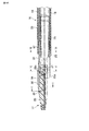
以下、本発明の第1の実施の形態を図1乃至図41を参照して説明する。図1は、本実施の形態の超音波処置装置のハンドピース1全体の概略構成を示す。本実施の形態の超音波処置装置は、超音波を利用して生体組織の切開、切除、或いは凝固等の処置を行うとともに、高周波による処置を行うこともできる超音波凝固切開処置装置である。 The first embodiment of the present invention will be described below with reference to FIGS. FIG. 1 shows a schematic configuration of the entire handpiece 1 of the ultrasonic treatment apparatus of the present embodiment. The ultrasonic treatment apparatus of the present embodiment is an ultrasonic coagulation / incision treatment apparatus that can perform treatment such as incision, excision, or coagulation of a living tissue using ultrasonic waves, and can also perform treatment with high frequency.
ハンドピース1は、図2に示すように振動子ユニット2と、プローブユニット(プローブ部)3と、ハンドルユニット(ハンドル部)4と、シースユニット(シース部)5の4つのユニットを有する。これら4つのユニットは、それぞれに取外し可能に連結されている。
As shown in FIG. 2, the handpiece 1 has four units: a
振動子ユニット2の内部には電流を超音波振動に変換する圧電素子によって超音波振動を発生させるための後述する振動子6(図41参照)が組み込まれている。圧電素子の外側は円筒状の振動子カバー7により覆われている。さらに、振動子ユニット2の後端には超音波振動を発生させるための電流を電源装置本体8より供給するためのケーブル9が延びている。
A vibrator 6 (see FIG. 41) to be described later for generating ultrasonic vibration by a piezoelectric element that converts electric current into ultrasonic vibration is incorporated in the
振動子カバー7内の超音波振動子6の前端部には超音波振動の振幅拡大を行なうホーン10の基端部が連結されている。このホーン10の先端部にはプローブ取付け用のねじ穴部10aが形成されている。
A base end portion of a
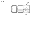
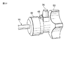
図36はプローブユニット3全体の外観を示す。このプローブユニット3は全体の長さが超音波振動の半波長の整数倍になるように設計されている。プローブユニット3は、金属製の棒状の振動伝達部材11を有する。振動伝達部材11の基端部にはホーン10のねじ穴部10aと螺合するためのねじ部12が設けられている。そして、このねじ部12が振動子ユニット2におけるホーン10のねじ穴部10aに螺着されている。これにより、プローブユニット3と、振動子ユニット2との間が組み付けられている。このとき、超音波振動子6とプローブユニット3との連結体には高周波電流が伝達される第1の高周波電気経路13が形成されている。
FIG. 36 shows the external appearance of the
振動伝達部材11の先端部にはプローブ先端3aが設けられている。プローブ先端3aは、ほぼJ字状の湾曲形状に形成されている。プローブユニット3はプローブ先端3aで処置に必要な振幅が得られるように、軸方向の途中の振動の節部数箇所で軸方向の断面積を減少させている。プローブユニット3の軸方向の途中にある振動の節位置の数箇所には弾性部材でリング状に形成されているゴムリングが取り付けられている。そして、これらのゴムリングによってプローブユニット3とシースユニット5との干渉を防止するようになっている。
A
プローブユニット3の軸方向における最も基端部側の振動の節位置にはフランジ部14が設けられている。図37に示すようにこのフランジ部14の外周面には、周方向の3箇所にキー溝状の係合凹部15が形成されている。
A
シースユニット5は、円筒体によって形成されたシース本体16と、シース本体16の先端に配設されたジョー17とを有する。シース本体16は、図7に示すように断面形状が円形の金属製の外筒18と、断面形状が非円形、例えばD形状の金属製の内筒19とを有する。外筒18と、内筒19との間には、ジョー17の駆動軸21を通すためのチャンネル22が形成されている。
The
図4Aに示すように外筒18の外周面は、絶縁チューブ23で被覆されている。図4Bに示すように内筒19の内周面は、絶縁材料によって絶縁コーティング24が形成されている。なお、内筒19の内周面に絶縁チューブを設けても良い。そして、内筒19の絶縁コーティング24によってプローブユニット3との間が電気的に絶縁されている。
As shown in FIG. 4A, the outer peripheral surface of the
外筒18の先端部には略円筒状の先端カバー25の基端部が固定されている。先端カバー25の基端部内周面側にはプローブユニット3を先端カバー25と接触しないように押えるパイプ状の押さえ部材26が取り付けられている。押さえ部材26の内側にはプローブユニット3を通すための円形断面のチャンネル20が形成されている。
A proximal end portion of a substantially cylindrical
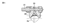
先端カバー25の先端部には図3Aに示すように外筒18の前方に向けて左右一対のジョー支持部25aが延設されている。これらのジョー支持部25aには図6に示すように2つの支点ピン27を介してジョー17の金属製のジョー本体28が回動可能に取り付けられている。このジョー17は図3Aに示すようにプローブユニット3のプローブ先端3aと対応するほぼJ字状の湾曲形状に形成されている。そして、ジョー17は、プローブユニット3のプローブ先端3aに対峙して2つの支点ピン27を中心に回動自在に支持されている(図6参照)。ジョー17は、プローブユニット3のプローブ先端3aから離れる方向に回動される開位置と、プローブユニット3のプローブ先端3a側に接近する方向に回動される閉位置とに回動操作される。ジョー17が閉位置とに回動操作されることにより、ジョー17とプローブユニット3のプローブ先端3aとの間で生体組織を把持するようになっている。
As shown in FIG. 3A, a pair of left and right
ジョー本体28は、PTFE等の樹脂からなる把持部材29と、この把持部材29を保持する金属製の把持部取付部材30とを有する。把持部取付部材30には、把持部材29がピン31により一定の角度回動可能に取り付けられている(図5参照)。さらに、ジョー本体28の後端には図4Aに示すようにピン28aを介して駆動軸21の先端部が連結されている。この駆動軸21は先端カバー25内を通り、続いて図7に示すようにシース本体16の外筒18と内筒19との間を通り、シース本体16の基端部側まで延出されている。
The
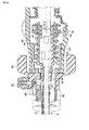
図8は、シース本体16の基端部を示す。シース本体16の基端部には、ハンドルユニット4と着脱するための着脱機構部31が設けられている。着脱機構部31は、樹脂材料で形成された円筒状の大径なつまみ部材32と、金属製の円筒体によって形成されたガイド筒体33と、樹脂材料で形成された円筒状の接続管体34とを有する。
FIG. 8 shows the proximal end portion of the
つまみ部材32は、前端部に配置されたリング状の第1の固定部32a、後端部に配置された円筒状の第2の固定部32bを有する。第1の固定部32aの内周面は、シース本体16の基端部外周面に固定されている。つまみ部材32の第2の固定部32bは、前端側に配置されたガイド筒体33の固定部35と、後端部側に配置されたハンドルユニット4との着脱部36とを有する。
The
ガイド筒体33は、前端部に配置された大径な前端フランジ部33aと、後端部側に配置された外周フランジ部33bとを有する。図9Aに示すようにガイド筒体33の前端フランジ部33aは、つまみ部材32の内部に挿入された状態で、樹脂製の2つの固定ねじ37でつまみ部材32に固定されている。
The
ガイド筒体33の内側には金属製のつなぎ管38が配設されている。このつなぎ管38の前端部内周面は、シース本体16の外筒18にレーザ溶接されて固定されている。さらに、つなぎ管38と、ガイド筒体33との間は、金属製の固定ねじ39によって固定されている。これにより、ガイド筒体33と、固定ねじ39と、つなぎ管38と、外筒18と、先端カバー25と、支点ピン27と、ジョー本体28との間が電気的に導通され、高周波電流が伝達されるシースユニット側電気経路40が形成されている。
A
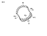
つまみ部材32の着脱部36は、図9Bに示すように周方向に沿って延設された傾斜面状のガイド溝41と、このガイド溝41の一端部に形成された係合凹部42とを有する。ガイド溝41は、つまみ部材32の後端部側に向かうにしたがって外径が小さくなるテーパー状の傾斜面を有する。係合凹部42は、ガイド溝41の傾斜面よりも小径な凹陥部によって形成されている。係合凹部42には、ハンドルユニット4側の後述する係合レバー43が係脱可能に係合されるようになっている。図33、34は係合凹部42に係合レバー43が係合された状態、図31、32は係合凹部42から係合レバー43が引き抜かれた係合解除状態をそれぞれ示す。
As shown in FIG. 9B, the attaching / detaching
接続管体34は、ガイド筒体33内にシース本体16の軸線方向にスライド自在に挿通されている。この接続管体34の先端部には、駆動軸21の基端部がピン21Aを介して固定されている(図10参照)。接続管体34の基端部には、図12、13に示す2つのガイド溝44を有する。ガイド溝44には、ハンドルユニット4側の後述する係合ピン45が係脱可能に係合されるようになっている。ガイド溝44の終端部には係合ピン45がシース本体16の軸線方向に移動することを規制する係合溝44aが形成されている。
The connecting
外周フランジ部33bは、非円形状の係合部46を有する。係合部46には、外周フランジ部33bの円形状の外周面の複数箇所、本実施の形態では3箇所を切欠させた3つの平面部46aが形成されている。3つの平面部46a間の各接合部には、平面部46aよりも大径な角部46bがそれぞれ形成されている。これにより、外周フランジ部33bには、略三角形状に近い断面形状の係合部46が形成されている。なお、この非円形状の係合部46は必ずしも略三角形状である必要は無く、四角形、五角形などの多角形など非円形であれば種々の形状が考えられる。
The outer
ハンドルユニット4は、主に固定ハンドル47と、保持筒48と、可動ハンドル49と、回動操作ノブ50と、高周波電流が伝達されるハンドルユニット側電気経路95とを有する。固定ハンドル47は、上部に保持筒48が配設されている。固定ハンドル47と保持筒48との間にはスイッチ保持部51を有する。スイッチ保持部51は、図35に示すように保持筒48の下端部に固定されたスイッチ取付け部52と、固定ハンドル47の上端部に固定されたカバー部材53とを有する。スイッチ取付け部52は、押しボタンスイッチである複数、本実施の形態では2つのハンドスイッチボタン(例えば切開用スイッチボタン54と凝固用スイッチボタン55)を有する。スイッチ取付け部52には、切開用スイッチボタン54によって操作される切開用スイッチ54aと、凝固用スイッチボタン55によって操作される凝固用スイッチ55aと、配線回路基板92とが組み込まれている。配線回路基板92には、一端が切開用スイッチ54aに接続された切開用配線93aと、一端が凝固用スイッチ55aに接続された凝固用配線93bと、一端がグランド用のコモン端子に接続されたグランド用の配線93cとが接続されている。これら3本の配線93a〜93cは丸められた状態でスイッチ保持部51内に組み込まれている。
The handle unit 4 mainly includes a fixed
可動ハンドル49は、上部にほぼU字状のアーム部56を有する。U字状のアーム部56は、図20に示すように2つのアーム56a,56bを有する。可動ハンドル49は、2つのアーム56a,56b間に保持筒48が挿入される状態で、保持筒48に組み付けられている。
The
アーム56a,56bはそれぞれ支点ピン57と、作用ピン58とを有する。保持筒48の両側部には、ピン受け穴部59と窓部60とがそれぞれ形成されている。各アーム56a,56bの支点ピン57は保持筒48のピン受け穴部59内に挿入されている。これにより、可動ハンドル49の上端部は、支点ピン57を介して保持筒48に回動可能に軸支されている。
Each of the
固定ハンドル47と可動ハンドル49の各下端部にはそれぞれ指掛け部61、62が設けられている。そして、ここに指をかけて握ることで支点ピン57を介して可動ハンドル49が回動し、固定ハンドル47に対して可動ハンドル49が開閉操作されるようになっている。
Finger hooks 61 and 62 are provided at lower ends of the fixed
可動ハンドル49の各作用ピン58は保持筒48の窓部60を通って保持筒48の内部に延出されている。保持筒48の内部には可動ハンドル49の操作力をジョー17の駆動軸21に伝達する操作力伝達機構63が設けられている。
Each
図16に示すように操作力伝達機構63は、主に金属製で円筒状のばね受け部材64と、樹脂製のスライダ部材65とを有する。ばね受け部材64は、保持筒48の中心線と同軸に配置され、プローブユニット3の挿入方向と同方向に延設されている。
As shown in FIG. 16, the operating
ばね受け部材64の基端部は、保持筒48の基端部に固定された後述する円筒状の接点ユニット66に軸回り方向に回動可能に、かつプローブユニット3の挿入方向と同方向に進退可能に連結されている。ばね受け部材64の先端部には前述したハンドルユニット4側の一対の係合ピン45が内方向に向けて突設されている。ハンドルユニット4とシースユニット5との連結時には、ハンドルユニット4側の一対の係合ピン45がシースユニット5のガイド溝44の終端部の係合溝44aに係脱可能に係合される。
The base end portion of the
ばね受け部材64の外周面には、コイルばね67と、前記スライダ部材65と、ストッパ68と、バネ受け69とが配設されている。バネ受け69には、コイルばね67の前端部が固定されている。ストッパ68は、スライダ部材65の後端側の移動位置を規制する。コイルばね67は、バネ受け69とスライダ部材65との間に一定の装備力量で装着されている。
A
スライダ部材65の外周面には周方向に沿ってリング状の係合溝65aが形成されている。この係合溝65aには図20に示すように可動ハンドル49の作用ピン58が挿入された状態で係合されている。そして、可動ハンドル49を握り、固定ハンドル47に対して可動ハンドル49が閉操作されるとこのときの可動ハンドル49の回動動作にともない作用ピン58が支点ピン57を中心に回動する。この支点ピン57の回動動作に連動しているスライダ部材65が軸方向に沿って前進方向に移動する。このとき、スライダ部材65にコイルばね67を介して連結されているばね受け部材64もスライダ部材65と一緒に進退動作する。これにより、一対の係合ピン45を介して接続管体34に可動ハンドル49の操作力が伝達され、ジョー17の駆動軸21が前進方向に移動する。そのため、ジョー17のジョー本体20が支点ピン21を介して回動するようになっている。
A ring-shaped
さらに、この操作によりジョー17の把持部材29とプローブユニット3のプローブ先端3aとの間で生体組織を挟む際に、プローブ先端3aの撓みに追従してピン31を支点として把持部材29が一定の角度回動して把持部材29の全長に渡り均一に力が掛かるようになっている。この状態で、超音波を出力することにより、血管等の生体組織の凝固、切開が可能となる。
Further, when the living tissue is sandwiched between the gripping
保持筒48の前端部には、リング状の軸受部70が形成されている。この軸受部70には、金属製で、円筒状の回転伝達部材71が軸回り方向に回動可能に連結されている。回転伝達部材71は、軸受部70の前方に突出される突出部72と、軸受部70から保持筒48の内部側に延設される大径部73とが形成されている。
A ring-shaped
突出部72には、回動操作ノブ50が外嵌される状態で固定されている。この回動操作ノブ50の前端部には、前記係合レバー43が配設されている。係合レバー43の中間部は、ピン74を介して突出部72に回動可能に連結されている。係合レバー43の基端部は、回動操作ノブ50の前面に形成されたレバー収納凹部75の内部側に延出されている。
The
回動操作ノブ50の前端部外周面には、係合レバー43を係合解除方向に操作する操作ボタン76が配設されている。この操作ボタン76には、下向きの作動ピン77が突設されている。作動ピン77は、回動操作ノブ50の壁穴を介してレバー収納凹部75の内部側に延出されている。作動ピン77の下端部には、係合レバー43の基端部がピン78を介して回動可能に連結されている。
An
突出部72の先端部には、回動操作ノブ50の抜け止めリング80が配設されている。突出部72の先端部には、雄ねじ部79が形成されている。抜け止めリング80の内周面には、雄ねじ部79と螺着される雌ねじ部80aが形成されている。そして、抜け止めリング80の雌ねじ部80aが突出部72の雄ねじ部79にねじ結合されることにより、回動操作ノブ50が回転伝達部材71に固定されている。
A retaining
図19に示すようにばね受け部材64のバネ受け69には金属製の4つの位置決めピン81が径方向外向きに突設されている。回転伝達部材71の大径部73には、ばね受け部材64の1つのピン81が挿入される長穴状の係合穴部82が形成されている。係合穴部82は、プローブユニット3の挿入方向と同方向に延設されている。これにより、可動ハンドル49の操作時にはピン81を係合穴部82に沿って移動させることにより、ばね受け部材64の進退動作が回転伝達部材71に伝達されることを防止する。
As shown in FIG. 19, four metal positioning pins 81 project radially outward from the
これに対し、回動操作ノブ50の回転操作時には、回動操作ノブ50と一緒に回転する回転伝達部材71の回転動作がピン81を介してばね受け部材64側に伝達される。これにより、回動操作ノブ50の回転操作時には、回動操作ノブ50と一緒に保持筒48の内部の回転伝達部材71と、ピン81と、ばね受け部材64と、スライダ部材65と、コイルばね67との組み付けユニットが一体的に軸回り方向に回転駆動されるようになっている。
On the other hand, during the rotation operation of the
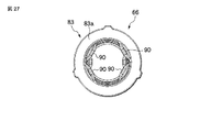
図26〜28は、円筒状の接点ユニット66を示す。接点ユニット66は、樹脂製の円筒状の電極保持部材83を有する。電極保持部材83は、図28に示すように外径の大きさが異なる3つ(第1〜第3)の電極受け部84,85,86を有する。先端部側の第1電極受け部84は、最も径が小さく、後端部側の第3電極受け部86は、最も径が大きい。
26 to 28 show a
図23に示すように第1電極受け部84は、1つの接点部材固定穴84aと、2つの貫通穴84b,84cとを有する。2つの貫通穴84b,84cの中心線は、接点部材固定穴84aの中心線に対して直交する位置に配置されている。
As shown in FIG. 23, the first
同様に、図24に示すように第2電極受け部85は、1つの接点部材固定穴85aと、2つの貫通穴85b,85cとを有する。図25に示すように第3電極受け部86は、1つの接点部材固定穴86aと、2つの貫通穴86b,86cとを有する。
Similarly, as shown in FIG. 24, the second
第1電極受け部84の接点部材固定穴84a、第2電極受け部85の接点部材固定穴85a、第3電極受け部86の接点部材固定穴86aの位置は、それぞれ電極保持部材83の周方向にずらした位置に配置されている。
The positions of the contact
図29および図30は、第1〜第3電極受け部84,85,86に組み付けられる電極部材87A,87B,87Cを示す。これらの電極部材87A,87B,87Cは、いずれも同じ形状に形成されている。ここでは、第1電極受け部84に組み付けられる電極部材87Aのみを説明し、他の第2、第3電極受け部85,86の電極部材87B,87Cの同一部分には同一の符号を付してその説明を省略する。
29 and 30
電極部材87Aは、1つの直線状の固定部87aと、2つの屈曲部87b,87cとを有する。直線状の固定部87aの一端に一方の屈曲部87b、他端に他方の屈曲部87cがそれぞれ配置される。これにより、図29に示すように電極部材87Aは、ほぼU字状に屈曲形成されている。
The
固定部87aの中央位置には穴88と、L字状の配線接続部89とを有する。2つの屈曲部87b,87cには中央位置に内側に向けて湾曲させる形状のくびれ部90がそれぞれ成形されている。
A central portion of the fixing
第1電極受け部84に電極部材87Aを組み付ける場合には電極部材87Aの固定部87aの穴88と、第1電極受け部84の接点部材固定穴85aとに固定ピン91が挿入される。この固定ピン91によって第1電極受け部84に電極部材87Aが固定される。このとき、第1電極受け部84の一方の貫通穴85bには、電極部材87Aの一方の屈曲部87bのくびれ部90、他方の貫通穴85cには、電極部材87Aの他方の屈曲部87cのくびれ部90がそれぞれ挿入される状態で配置されている。第2電極受け部85に電極部材87Bを組み付ける場合および第3電極受け部86に電極部材87Cを組み付ける場合も同様である。
When the
図22に示すように接点ユニット66の電極保持部材83の後端部には大径な固定フランジ部83aが形成されている。固定フランジ部83aの外周面には、複数、本実施の形態では3箇所に係合凸部83bが突設されている。保持筒48の後端部内周面には固定フランジ部83aの3つの係合凸部83bと対応する位置に係合凹部48aがそれぞれ形成されている。保持筒48に電極保持部材83を組み付ける場合には固定フランジ部83aの3つの係合凸部83bが保持筒48の係合凹部48aに挿入される状態で係合固定される。これにより、保持筒48に対する電極保持部材83の軸回り方向の回転が規制される。
As shown in FIG. 22, a fixed
保持筒48には、電極保持部材83の固定フランジ部83aと当接する段差部48bが形成されている。この段差部48bに電極保持部材83の固定フランジ部83aが突き当てられた状態で固定ねじ48cによって電極保持部材83が保持筒48にねじ固定されている。これにより、保持筒48に対する電極保持部材83の軸方向の移動が規制される。
The holding
接点ユニット66に組み付けられた3つの電極部材87A,87B,87Cの配線接続部89には、スイッチ保持部51に組み込まれた3本の配線93a〜93cの各端部がそれぞれ接続されている。
The respective ends of the three
接点ユニット66には、さらに図21に示すように金属製の板ばねからなるほぼC字状の電気接点部材96が設けられている。電気接点部材96は、ばね受け部材64の基端部の外周面に接続されている。
The
前記ハンドルユニット側電気経路95は、電気接点部材96と、ばね受け部材64と、位置決めピン81と、回転伝達部材71とからなる。
The handle unit side
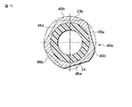
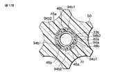
回転伝達部材71の内周面には、軸方向に沿ってほぼ中央位置にシースユニット5の外周フランジ部33bに対して係脱可能に係合する係合手段94が設けられている。図17A,17Bに示すようにこの係合手段94は、シースユニット5とハンドルユニット4との連結時に、外周フランジ部33bが挿入される挿入穴部94aと、挿入穴部94a内に配置された導電ゴムリング(付勢手段)94bとを有する。
Engagement means 94 is provided on the inner peripheral surface of the
導電ゴムリング94bの内周面形状は、外周フランジ部33bの係合部46とほぼ同形状、すなわち円形状の内周面の複数箇所、本実施の形態では3箇所を切欠させた3つの平面部94b1と、3つの平面部94b1間の各接合部に配置され、平面部94b1よりも大径な3つの角部94b2とがそれぞれ形成されている。これにより、ほぼ三角形状に近い断面形状に形成されている。そのため、図17Aに示すように導電ゴムリング94bの内周面形状と、外周フランジ部33bの係合部46とが対応している位置、すなわち外周フランジ部33bの3つの角部46bと、導電ゴムリング94bの3つの角部94b2とがそれぞれ一致している状態では、導電ゴムリング94bは自然状態の非圧縮位置で保持される。これに対し、ハンドルユニット4とシースユニット5との間をシースユニット5の中心軸の軸回り方向に相対的に回転させることにより、図17Bに示すように導電ゴムリング94bは外周フランジ部33bの3つの角部46bに圧接される圧接位置に切替えられる。このとき、外周フランジ部33bの3つの角部46bは、導電ゴムリング94bの3つの平面部94b1と当接することにより、圧縮される。
The shape of the inner peripheral surface of the
本実施の形態では、シースユニット5とハンドルユニット4との連結時に、シースユニット5の外周フランジ部33bが導電ゴムリング94bの内部に真っ直ぐに挿通される挿入動作時(図31および図32参照)には、図17Aに示すように導電ゴムリング94bは自然状態の非圧縮位置で保持される。このとき、ハンドルユニット4側の係合レバー43は、シースユニット5のつまみ部材32のガイド溝41の傾斜面に乗り上げた状態で保持される。その後、シースユニット5のつまみ部材32をハンドルユニット4に対して軸回り方向に回転させることにより、図33および図34に示すようにハンドルユニット4側の係合レバー43がガイド溝41の一端部の係合凹部42に挿入される状態で係合される。このとき、図17Bに示すように導電ゴムリング94bは外周フランジ部33bの3つの角部46bに圧接される圧接位置に切替えられる。これにより、シースユニット側電気経路40(ガイド筒体33と、固定ねじ39と、つなぎ管38と、外筒18と、先端カバー25と、支点ピン27と、ジョー本体28との間に形成される)とハンドルユニット側電気経路95(電気接点部材96と、ばね受け部材64と、位置決めピン81と、回転伝達部材71との間に形成される)との間が導電ゴムリング94bを介して導通されるようになっている。このとき、シースユニット5とハンドルユニット4との連結体には、高周波電流が伝達される第2の高周波電気経路97が形成されている。
In the present embodiment, when the
ハンドルユニット4は、図21に示すようにばね受け部材64の内周面に絶縁材料によって形成された管状部材98を有する。管状部材98は、ばね受け部材64の内周面に固定されている。これにより、プローブユニット3とハンドルユニット4との接続時には第1の高周波電気経路13と第2の高周波電気経路97との間が管状部材98によって絶縁される。
The handle unit 4 has a
管状部材98の内周面には、プローブユニット3のフランジ部14の3つの係合凹部15(図37参照)と対応する3つの係合凸部99が形成されている。プローブユニット3とハンドルユニット4との接続時には、プローブユニット3のフランジ部14の3つの係合凹部15に管状部材98の3つの係合凸部99が係脱可能に係合される。これにより、プローブユニット3とハンドルユニット4の管状部材98との回転方向の位置が規制される。そのため、回動操作ノブ50の回転操作時には保持筒48の内部の組み付けユニットと一緒にプローブユニット3と振動子ユニット2との連結体が一体的に回転駆動されるようになっている。
Three engagement
なお、プローブユニット3のフランジ部14と管状部材98との間の係合部は、上記構成に限定されるものではない。例えば、管状部材98をD字状の断面形状に形成し、プローブユニット3のフランジ部14をこれに対応するD字状の断面形状に形成してもよい。
The engaging portion between the
接点ユニット66には、振動子ユニット2の前端部が着脱可能に連結される。振動子ユニット2の後端の1本のケーブル9の内部には、図40に示すように超音波振動子用の2つの配線101、102と、高周波通電用の2つの配線103、104と、スイッチ保持部51内の配線回路基板92に接続される3つの配線105,106,107が組み込まれている。超音波振動子用の2つの配線101、102の先端部は超音波振動子6に接続されている。高周波通電用の一方の配線103の先端部は、超音波振動子6に接続されている。
A front end portion of the
振動子ユニット2の後端には、4つの電気接続用の第1〜第4の導電板111〜114が配設されている。第1の導電板111には、高周波通電用の他方の配線104の先端部が接続されている。第2〜第4の導電板112〜114には、3つの配線105,106,107がそれぞれ接続されている。
Four electrical connection first to fourth
図41は、振動子ユニット2の前端部の内部構成を示す。振動子カバー7の先端部には、接続円筒部121が形成されている。この接続円筒部121の外周面にはリングの一部が切欠された板ばね状のCリング122が装着されている。接続円筒部121の内側には外径寸法が異なる3段(第1〜第3)の円筒部123〜125が突設されている。第1の円筒部123は、外径が最も小さく、接続円筒部121の先端からの突出長さが最も長い。第2の円筒部124は、外径が第1の円筒部123よりも大きく、接続円筒部121の先端からの突出長さが第1の円筒部123よりも短い。第3の円筒部125は、外径が最も大きく、接続円筒部121の先端からの突出長さが第2の円筒部124よりも短い。
FIG. 41 shows the internal configuration of the front end portion of the
第1の円筒部123の外周面には、円筒状の第1の接点部材131が装着されている。同様に、第2の円筒部124の外周面には、円筒状の第2の接点部材132、第3の円筒部125の外周面には、円筒状の第3の接点部材133がそれぞれ装着されている。第1の接点部材131には、第2の導電板112、第2の接点部材132には、第3の導電板113、第3の接点部材133には、第4の導電板114がそれぞれ接続されている。
A cylindrical
第1の円筒部123の内周面には、円筒状の第4の接点部材134が装着されている。第4の接点部材134は、第1の導電板111に接続されている。
A cylindrical
ハンドルユニット4と振動子ユニット2との連結時には、ハンドルユニット4の接点ユニット66と、振動子ユニット2の前端部とが接続される。このとき、接点ユニット66の電極部材87Aと振動子ユニット2の第1の接点部材131との間が接続される。同時に、接点ユニット66の電極部材87Bと振動子ユニット2の第2の接点部材132との間、接点ユニット66の電極部材87Cと振動子ユニット2の第3の接点部材133との間、および接点ユニット66のC字状電気接点部材96と振動子ユニット2の第4の接点部材134との間がそれぞれ接続される。
When the handle unit 4 and the
次に、本実施の形態の作用を説明する。本実施の形態の超音波処置装置のハンドピース1は、図2に示すように振動子ユニット2と、プローブユニット3と、ハンドルユニット4と、シースユニット5の4つのユニットに取外し可能になっている。そして、ハンドピース1の使用時には、振動子ユニット2と、プローブユニット3との間が連結される。これにより、振動子ユニット2とプローブユニット3との連結体に高周波電流が伝達される第1の高周波電気経路13が形成される。
Next, the operation of the present embodiment will be described. As shown in FIG. 2, the handpiece 1 of the ultrasonic treatment apparatus according to the present embodiment can be detached from the four units of the
続いて、ハンドルユニット4と、シースユニット5との間が連結される。ハンドルユニット4と、シースユニット5との連結時には、シースユニット5のつまみ部材32を把持した状態で、接続管体34がハンドルユニット4の回転伝達部材71の内部に挿入される。このシースユニット5とハンドルユニット4との連結時には、図31および図32に示すようにハンドルユニット4側の係合レバー43は、シースユニット5のつまみ部材32のガイド溝41の傾斜面に乗り上げた状態で保持される。このとき、図17Aに示すように導電ゴムリング94bの内周面形状と、外周フランジ部33bの係合部46とが対応している位置、すなわち外周フランジ部33bの3つの角部46bと、導電ゴムリング94bの3つの角部94b2とがそれぞれ一致している状態で保持される。そのため、シースユニット5の外周フランジ部33bが導電ゴムリング94bの内部に真っ直ぐに挿通される。この挿入動作時には、図17Aに示すように導電ゴムリング94bは自然状態の非圧縮位置で保持される。この状態では、シースユニット側電気経路40とハンドルユニット側電気経路95との間は導通されていない。
Subsequently, the handle unit 4 and the
続いて、この挿入動作の終了後、シースユニット5のつまみ部材32をハンドルユニット4に対して軸回り方向に回転させる操作が行われる。この操作により、図33および図34に示すようにハンドルユニット4側の係合レバー43がガイド溝41の一端部の係合凹部42に挿入される状態で係合される。このとき、図17Bに示すように導電ゴムリング94bは外周フランジ部33bの3つの角部46bに圧接される圧接位置に切替えられる。これにより、シースユニット側電気経路40とハンドルユニット側電気経路95との間が導電ゴムリング94bを介して導通される。この結果、シースユニット5とハンドルユニット4との連結体には、高周波電流が伝達される第2の高周波電気経路97が形成される。
Subsequently, after this insertion operation is completed, an operation of rotating the
このシースユニット5の軸回り方向の回転操作時には、同時にハンドルユニット4側の一対の係合ピン45がシースユニット5のガイド溝44の終端部の係合溝44aに係脱可能に係合される。これにより、ハンドルユニット4側のばね受け部材64とシースユニット5側の接続管体34との間が係合ピン45を介して連結される。その結果、固定ハンドル47に対して可動ハンドル49を閉操作する際のハンドルユニット4側の操作力がシースユニット5側のジョー17の駆動軸21に伝達可能となる。この状態が、シースユニット5とハンドルユニット4との連結状態である。
When the
その後、シースユニット5とハンドルユニット4との連結体と、超音波振動子6とプローブユニット3との連結体とが合体される状態に組み付けられる。この組み付け作業時には、ハンドルユニット4の接点ユニット66と、振動子ユニット2の前端部とが接続される。このとき、接点ユニット66の電極部材87Aと振動子ユニット2の第1の接点部材131との間が接続される。同時に、接点ユニット66の電極部材87Bと振動子ユニット2の第2の接点部材132との間、接点ユニット66の電極部材87Cと振動子ユニット2の第3の接点部材133との間、および接点ユニット66のC字状電気接点部材96と振動子ユニット2の第4の接点部材134との間がそれぞれ接続される。これにより、シースユニット5とハンドルユニット4との連結体の第2の高周波電気経路97がケーブル9の内部の高周波通電用の配線104と接続される。さらに、ケーブル9の内部の3つの配線105,106,107とスイッチ保持部51内の配線回路基板92とが接続される。この状態が、ハンドピース1の組み付け作業の終了状態である。
Thereafter, the coupling body of the
そして、このハンドピース1の使用時には、固定ハンドル47に対して可動ハンドル49を閉操作することにより、この可動ハンドル4の操作に連動して駆動軸21を軸方向に移動させ、この駆動軸21の軸方向の進退動作に連動してジョー17をプローブユニット3のプローブ先端3aに対して開閉駆動する。これにより、ジョー17とプローブユニット3のプローブ先端3aとの間に生体組織を把持する。
When the handpiece 1 is used, the
この状態で、固定ハンドル47の切開用スイッチボタン54または凝固用スイッチボタン55のいずれか一方が選択的に押し込み操作される。凝固用スイッチボタン55の押し込み操作時には、プローブユニット3のプローブ先端3aに高周波電流を導通する第1の高周波電気経路13と、シースユニット5のジョー本体28に高周波電流を導通する第2の高周波電気経路97とにそれぞれ通電される。これにより、プローブユニット3のプローブ先端3aと、シースユニット5のジョー本体28とによって高周波処置用の2つのバイポーラ電極が構成される。そして、プローブユニット3のプローブ先端3aと、シースユニット5のジョー本体28との2つのバイポーラ電極間に高周波電流を通電することにより、ジョー17とプローブユニット3のプローブ先端3aとの間の生体組織に対してバイポーラによる高周波処置を行うことができる。
In this state, either the
切開用スイッチボタン54の押し込み操作時には、前記高周波通電と同時に超音波振動子6に駆動電流が通電され、超音波振動子6が駆動される。これにより、超音波振動子6からの超音波振動を振動伝達部材11を介してプローブ先端3aに伝達することにより、前記高周波通電と同時に超音波を利用して生体組織の切開、切除等の処置を行うことができる。なお、超音波を利用して生体組織の凝固処置を行うこともできる。
When the
また、回動操作ノブ50の回転操作時には、回動操作ノブ50と一緒に回転する回転伝達部材71の回転動作がピン81を介してばね受け部材64側に伝達される。これにより、回動操作ノブ50の回転操作時には、回動操作ノブ50と一緒に保持筒48の内部の回転伝達部材71と、ピン81と、ばね受け部材64と、スライダ部材65と、コイルばね67との組み付けユニットが一体的に軸回り方向に回転駆動される。さらに、保持筒48の内部のばね受け部材64と一緒に回転する管状部材98を介して回動操作ノブ50の回転操作力がプローブユニット3の振動伝達部材11に伝達される。これにより、保持筒48の内部の組み付けユニットと、振動子ユニット2とプローブユニット3との連結体が一緒に一体的に軸回り方向に回転駆動される。
Further, during the rotation operation of the
そこで、上記構成のものにあっては次の効果を奏する。すなわち、本実施の形態の超音波処置装置のハンドピース1では、シースユニット5のガイド筒体33の前端フランジ部33aに略三角形状の係合部46を設けている。回転伝達部材71の内周面には導電ゴムリング94bを設けている。そして、シースユニット5とハンドルユニット4との連結時には、シースユニット5のつまみ部材32をハンドルユニット4に対して軸回り方向に回転させることにより、図17Bに示すように導電ゴムリング94bが外周フランジ部33bの3つの角部46bに圧接される圧接位置に切替えられるようにした。このように、シースユニット側電気経路40とハンドルユニット側電気経路95との間を導電ゴムリング94bの圧接部分を介して導通させることにより、シースユニット側電気経路40とハンドルユニット側電気経路95との間の導通を安定させることができる。そのため、バイポーラの高周波処置が可能なハンドピース1のハンドルユニット4とシースユニット5との間を着脱可能な構成にした場合にシースユニット側電気経路40とハンドルユニット側電気経路95との間の導通が不安定になることを防止することができる。
Therefore, the above configuration has the following effects. That is, in the handpiece 1 of the ultrasonic treatment apparatus according to the present embodiment, the substantially
さらに、ハンドルユニット4内に管状部材98を設けたので、プローブユニット3とハンドルユニット4との接続時に第1の高周波電気経路13と第2の高周波電気経路97との間を管状部材98によって絶縁させることができる。プローブユニット3とハンドルユニット4との接続時には、プローブユニット3のフランジ部14の3つの係合凹部15に管状部材98の3つの係合凸部99を係脱可能に係合させる。これにより、プローブユニット3とハンドルユニット4の管状部材98との回転方向の位置が規制される。そのため、回動操作ノブ50の回転操作時に保持筒48の内部の組み付けユニットと一緒にプローブユニット3と振動子ユニット2との連結体が一体的に回転駆動させることができる。このように管状部材98によってプローブユニット3とハンドルユニット4の管状部材98との回転方向の位置規制手段を兼用させたので、ハンドルユニット4内の部品数を低減することができる。
Further, since the
さらに、ハンドルユニット4に対してシースユニット5を着脱可能に連結したので、シースユニット5の先端部のジョー17の把持部材29が磨耗した場合などにシースユニット5のみを交換することができる。そのため、ハンドルユニット4に対してシースユニット5が一体的に組み付けられている場合のようにハンドルユニット4とシースユニット5との組み付け部品全体を交換する場合に比べてコストを下げることができる。
Further, since the
本実施の形態の超音波処置装置のハンドピース1では、振動子ユニット2の後端の1本のケーブル9の内部に、図40に示すように超音波振動子用の2つの配線101、102と、高周波通電用の2つの配線103、104と、スイッチ保持部51内の配線回路基板92に接続される3つの配線105,106,107とを組み込む構成にした。そのため、ハンドピース1に複数本のケーブルを接続する必要がないので、ハンドピース1の操作性を高めることができる。
In the handpiece 1 of the ultrasonic treatment apparatus according to the present embodiment, two
さらに、本実施の形態では固定ハンドル47にスイッチ保持部51を設け、固定ハンドル47に切開用スイッチボタン54と凝固用スイッチボタン55を内蔵させて組み込んでいる。これら切開用スイッチボタン54と凝固用スイッチボタン55の接続配線はハンドピース1の内部に配設し、振動子ユニット2の後端の1本のケーブル9の内部に組み込まれた3つの配線105,106,107に接続させている。そのため、例えばハンドピース1に切開用スイッチボタン54と凝固用スイッチボタン55を外付けで装着した場合のように切開用スイッチボタン54と凝固用スイッチボタン55用の接続配線がハンドピース1に連結されることがない。その結果、ハンドピース1に接続される接続コード類をさらに少なくすることができる。
Furthermore, in the present embodiment, the
図42A,42Bは、第1の実施の形態の超音波処置装置のハンドルユニット4とシースユニット5との着脱部分の第1の変形例を示す。第1の実施の形態では、ハンドルユニット4の回転伝達部材71の内周面に導電ゴムリング94bを設けている。そして、シースユニット5の外周フランジ部33bの3つの角部46bを導電ゴムリング94bの3つの平面部94b1に当接させることにより、導電ゴムリング94bを圧縮させてシースユニット側電気経路40とハンドルユニット側電気経路95との間を導電ゴムリング94bを介して導通させる構成を示した。本変形例は、この導電ゴムリング94bに代えて3つの金属製の板ばね部材115を設けたものである。各板ばね部材115は、回転伝達部材71の内周面の周方向に等間隔で並設されている。各板ばね部材115間にはシースユニット5の外周フランジ部33bと非接触状態で保持される空間部116が形成されている。
42A and 42B show a first modified example of the attachment / detachment portion between the handle unit 4 and the
そして、図42Aに示すように外周フランジ部33bの3つの角部46bが各板ばね部材115間の空間部116とそれぞれ一致している状態では、各板ばね部材115は自然状態の非圧縮位置で保持される。これに対し、ハンドルユニット4とシースユニット5との間をシースユニット5の中心軸の軸回り方向に相対的に回転させることにより、図42Bに示すように外周フランジ部33bの3つの角部46bによって各板ばね部材115が圧接される圧接位置に切替えられる。このとき、各板ばね部材115は、外周フランジ部33bの3つの角部46bに押圧されることにより、圧縮される。
Then, as shown in FIG. 42A, in a state where the three
本変形例では、シースユニット5とハンドルユニット4との連結時に、シースユニット5の外周フランジ部33bが回転伝達部材71の内部に真っ直ぐに挿通される挿入動作時(図31および図32参照)には、図42Aに示すように各板ばね部材115は自然状態の非圧縮位置で保持される。このとき、ハンドルユニット4側の係合レバー43は、シースユニット5のつまみ部材32のガイド溝41の傾斜面に乗り上げた状態で保持される。その後、シースユニット5のつまみ部材32をハンドルユニット4に対して軸回り方向に回転させることにより、図33および図34に示すようにハンドルユニット4側の係合レバー43がガイド溝41の一端部の係合凹部42に挿入される状態で係合される。このとき、図42Bに示すように各板ばね部材115は、外周フランジ部33bの3つの角部46bに押圧されることにより、圧縮される。これにより、シースユニット側電気経路40とハンドルユニット側電気経路95との間が各板ばね部材115を介して導通されるようになっている。このとき、シースユニット5とハンドルユニット4との連結体には、高周波電流が伝達される第2の高周波電気経路97が形成される。
In this modification, when the
したがって、本変形例でも第1の実施の形態の超音波処置装置のハンドルユニット4とシースユニット5との着脱部分と同様の作用が得られる。
Therefore, also in this modification, the same operation as that of the attaching / detaching portion of the handle unit 4 and the
図43は、第1の実施の形態の超音波処置装置のハンドルユニット4とシースユニット5との着脱部分の第2の変形例を示す。本変形例は、第1の変形例の板ばね部材115に代えて図43に示す付勢部材117を設けたものである。この付勢部材117は、ゴム製のリング117aと、一対の金属接点117bとを有する。ゴム製リング117aは、ほぼ長円形状に形成されている。一対の金属接点117bは、ゴム製リング117aの長円の長辺部分の中央位置に離間対向配置されている。
FIG. 43 shows a second modification of the attachment / detachment portion between the handle unit 4 and the
そして、外周フランジ部33bの3つの角部46bが各付勢部材117間の空間部116とそれぞれ一致している状態では、各付勢部材117は自然状態の非圧縮位置(図43の状態)で保持される。外周フランジ部33bの3つの角部46bによって各付勢部材117が圧接される圧接位置に切替えられた場合には、各付勢部材117は、外周フランジ部33bの3つの角部46bにゴム製リング117aの長円の長辺の中央部分が押圧されることにより、圧縮される。このとき、一対の金属接点117b間が接触される。
In the state where the three
したがって、本変形例でも第1の実施の形態の超音波処置装置のハンドルユニット4とシースユニット5との着脱部分と同様の作用が得られる。
Therefore, also in this modification, the same operation as that of the attaching / detaching portion of the handle unit 4 and the
また、図44乃至図46は本発明の第2の実施の形態の超音波処置装置のハンドピース1の要部構成を示す。第1の実施の形態(図1乃至図41参照)では、プローブユニット3とハンドルユニット4との接続時に第1の高周波電気経路13と第2の高周波電気経路97との間を絶縁させる管状部材98をハンドルユニット4に組み込んだ構成を示した。
FIGS. 44 to 46 show the main configuration of the handpiece 1 of the ultrasonic treatment apparatus according to the second embodiment of the present invention. In the first embodiment (see FIGS. 1 to 41), a tubular member that insulates between the first high-frequency
本実施の形態は、第1の実施の形態の管状部材98に相当する絶縁材料製の管状部材141をシースユニット5側に設けたものである。すなわち、本実施の形態ではシースユニット5のシース本体16の基端部に設けられている着脱機構部31の接続管体34と絶縁材料製の管状部材141とが連結された状態で一体的に形成されている。管状部材141の基端部にはハンドルユニット4側の後述する係合ピン45が係脱可能に係合される2つのガイド溝44(図12、13を参照)を有する。
In the present embodiment, a
管状部材141の内周面には、プローブユニット3のフランジ部14の3つの係合凹部15(図37参照)と対応する3つの係合凸部99(図21参照)が形成されている。プローブユニット3とハンドルユニット4との接続時には、プローブユニット3のフランジ部14の3つの係合凹部15にシースユニット5の管状部材141の3つの係合凸部99が係脱可能に係合される。これにより、プローブユニット3とシースユニット5の管状部材141との回転方向の位置が規制される。そのため、回動操作ノブ50の回転操作時には保持筒48の内部の組み付けユニットと一緒にプローブユニット3と振動子ユニット2との連結体が一体的に回転駆動されるようになっている。
On the inner peripheral surface of the
なお、この変更部分以外の構成は、第1の実施の形態とほぼ同一である。そのため、図44乃至図46中で、第1の実施の形態と同一部分には同一の符号を付してその説明を省略する。 The configuration other than the changed portion is almost the same as that of the first embodiment. Therefore, in FIGS. 44 to 46, the same portions as those of the first embodiment are denoted by the same reference numerals, and the description thereof is omitted.
そこで、本実施の形態では、シースユニット5側に管状部材141を設けている。そのため、回動操作ノブ50の回転操作時に保持筒48の内部の組み付けユニットと一緒にプローブユニット3と振動子ユニット2との連結体が一体的に回転駆動される際に、管状部材141におけるプローブユニット3との係合部分が破損した場合に管状部材141を安価なシースユニット5と一緒に交換することができる。その結果、管状部材141の破損時に、高価なハンドルユニット4を交換する必要がないので、ハンドピース1の修理を安価に行うことができる。
Therefore, in the present embodiment, the
さらに、シースユニット5側に管状部材141を設けることにより、シースユニット5の接続管体34と絶縁材料製の管状部材141とを一体的に形成することができる。そのため、ハンドルユニット4の内部の構成部品点数を第1の実施の形態よりも少なくすることができるので、ハンドルユニット4の保持筒48の内部構成を簡素化することができる。その結果、ハンドルユニット4の保持筒48全体の軸方向の長さを第1の実施の形態よりも短くすることができ、ハンドピース1全体の小型化を図ることができる。
Furthermore, by providing the
なお、本発明は上記実施の形態に限定されるものではなく、本発明の要旨を逸脱しない範囲で種々変形実施できることは勿論である。 In addition, this invention is not limited to the said embodiment, Of course, various deformation | transformation can be implemented in the range which does not deviate from the summary of this invention.
4…ハンドルユニット(ハンドル部)、5…シースユニット(シース部)、33b…外周フランジ部、40…シースユニット側電気経路、46…係合部、94b…導電ゴムリング(付勢手段)、95…ハンドルユニット側電気経路、97…高周波電気経路。 4 ... handle unit (handle part), 5 ... sheath unit (sheath part), 33 b ... outer peripheral flange part, 40 ... sheath unit side electric path, 46 ... engagement part, 94 b ... conductive rubber ring (biasing means), 95 ... handle unit side electrical path, 97 ... high frequency electrical path.
Claims (11)
先端部および基端部を有し、前記基端部が前記超音波振動子に連結され、前記超音波振動子から出力される超音波が伝達されるプローブ部と、
先端部および基端部を有する円筒体によって形成され、前記プローブ部が挿脱可能に挿入されるシース部、前記シース部は、前記先端部に前記プローブ部に対峙して回動自在に支持されるジョーを有する,と、
前記シース部の前記基端部に着脱可能に連結され、前記ジョーを前記プローブ部に対して開閉操作するハンドル部、前記ハンドル部は前記超音波振動子が着脱自在に接続される振動子接続部を有する,と、
前記シース部と前記ハンドル部との連結体に設けられ、高周波電流が伝達される高周波電気経路と、
を具備し、
前記高周波電気経路は、
前記シース部側に配置されたシース部側電気経路と、
前記ハンドル部側に配置されたハンドル部側電気経路と、
前記シース部と前記ハンドル部との接続動作にともない前記シース部側電気経路と前記ハンドル部側電気経路との接続動作を行う電気接続部と、
を有し、
前記電気接続部は、
前記シース部の前記基端部に配置され、前記シース部の外周に形成されるとともに、前記シース部側電気経路に接続された外周フランジ部と、
前記ハンドル部の内部に配置され、前記外周フランジ部に対して係脱可能に係合する係合部と、
を有し、
前記係合部は、前記シース部と前記ハンドル部との連結時に、前記外周フランジ部が挿入される挿入穴構成部と、
前記挿入穴構成部内に配置され、前記外周フランジ部に対して非圧接状態で保持される非圧接位置と、前記外周フランジ部に対して圧接される圧接位置とに切替えられ、前記圧接位置で前記シース部側電気経路と前記ハンドル部側電気経路との間を導通させる付勢部と、
を具備することを特徴とする超音波処置装置。 An ultrasonic transducer that generates ultrasonic vibrations;
A probe portion having a distal end portion and a proximal end portion, wherein the proximal end portion is coupled to the ultrasonic transducer, and an ultrasonic wave output from the ultrasonic transducer is transmitted;
A sheath part that is formed by a cylindrical body having a distal end part and a proximal end part and into which the probe part is removably inserted, and the sheath part is rotatably supported by the distal end part against the probe part. And have Joe
A handle part that is detachably connected to the base end part of the sheath part and opens and closes the jaw with respect to the probe part, and the handle part is a vibrator connection part to which the ultrasonic vibrator is detachably connected And having
A high-frequency electrical path that is provided in a coupling body between the sheath portion and the handle portion and through which high-frequency current is transmitted;
Comprising
The high-frequency electrical path is
A sheath part side electrical path disposed on the sheath part side;
A handle portion side electrical path disposed on the handle portion side;
An electrical connection part that performs a connection operation between the sheath part side electrical path and the handle part side electrical path in connection with the connection operation of the sheath part and the handle part;
Have
The electrical connection portion is
An outer peripheral flange portion disposed at the base end portion of the sheath portion, formed on the outer periphery of the sheath portion, and connected to the sheath portion-side electrical path;
An engaging portion disposed inside the handle portion and detachably engaged with the outer peripheral flange portion;
Have
The engaging portion includes an insertion hole constituting portion into which the outer peripheral flange portion is inserted when the sheath portion and the handle portion are connected.
Switched between a non-pressure contact position that is disposed in the insertion hole component and is held in a non-pressure contact state with respect to the outer peripheral flange portion, and a pressure contact position that is pressed against the outer peripheral flange portion. An urging portion for conducting between the sheath portion side electrical path and the handle portion side electrical path;
An ultrasonic treatment apparatus comprising:
前記付勢部は、前記ハンドル部の内部に配置され、前記挿入穴構成部内に前記外周フランジ部が前記シース部の軸方向に沿って挿入される挿入動作位置では前記外周フランジ部に対して前記非圧接位置で保持され、前記外周フランジ部が前記挿入動作位置から前記シース部の中心軸の軸回り方向に回転する動作にともない前記圧接位置に切替えられることを特徴とする請求項1に記載の超音波処置装置。 The outer peripheral flange portion has an outer peripheral portion formed in a non-circular irregular shape,
The urging portion is disposed inside the handle portion, and the insertion portion is inserted into the insertion hole forming portion along the axial direction of the sheath portion at an insertion operation position with respect to the outer flange portion. 2. The pressure contact position according to claim 1, wherein the outer peripheral flange portion is held at a non-pressure contact position and is switched to the pressure contact position in accordance with an operation in which the outer peripheral flange portion rotates in a direction around an axis of a central axis of the sheath portion. Ultrasonic treatment device.
前記シース部と前記ハンドル部との接続時には、前記ゴム部を前記外周フランジ部に圧接させて前記シース部側電気経路と前記ハンドル部側電気経路との間を導通させる方向に付勢することを特徴とする請求項2に記載の超音波処置装置。 The urging portion has a ring-shaped rubber portion,
When the sheath portion and the handle portion are connected, the rubber portion is pressed against the outer peripheral flange portion and urged in a direction in which the sheath portion-side electrical path and the handle portion-side electrical path are electrically connected. The ultrasonic treatment apparatus according to claim 2, wherein the apparatus is an ultrasonic treatment apparatus.
前記シース部と前記ハンドル部との接続時には、前記付勢部材を前記外周フランジ部に圧接させて前記シース部側電気経路と前記ハンドル部側電気経路との間を導通させる方向に付勢することを特徴とする請求項1に記載の超音波処置装置。 The urging portion has a leaf spring-like urging member,
At the time of connection between the sheath portion and the handle portion, the biasing member is pressed against the outer peripheral flange portion and biased in a direction in which the sheath portion-side electrical path and the handle portion-side electrical path are electrically connected. The ultrasonic treatment apparatus according to claim 1.
先端部および基端部を有し、前記基端部が前記超音波振動子に連結され、前記超音波振動子から出力される超音波が伝達されるプローブ部と、
前記超音波振動子と前記プローブ部との連結体に設けられ、高周波電流が伝達される第1の高周波電気経路と、
先端部および基端部を有する円筒体によって形成され、前記プローブ部が挿脱可能に挿入されるシース部、前記シース部は、前記先端部に前記プローブ部に対峙して回動自在に支持されるジョーを有する,と、
前記シース部の前記基端部に着脱可能に連結され、前記ジョーを前記プローブ部に対して開閉操作するハンドル部、前記ハンドル部は前記超音波振動子が着脱自在に接続される振動子接続部を有する,と、
前記シース部と前記ハンドル部との連結体に設けられ、高周波電流が伝達される第2の高周波電気経路と、
を具備し、
前記第2の高周波電気経路は、
前記シース部側に配置されたシース部側電気経路と、
前記ハンドル部側に配置されたハンドル部側電気経路と、
前記シース部と前記ハンドル部との接続動作にともない前記シース部側電気経路と前記ハンドル部側電気経路との接続動作を行う電気接続部と、
を有し、
前記電気接続部は、
前記シース部の前記基端部に配置され、前記シース部の外周に形成されるとともに、前記シース部側電気経路に接続された外周フランジ部と、
前記ハンドル部の内部に配置され、前記外周フランジ部に対して係脱可能に係合する係合部と、
を有し、
前記係合部は、前記シース部と前記ハンドル部との連結時に、前記外周フランジ部が挿入される挿入穴構成部と、
前記挿入穴構成部内に配置され、前記ハンドル部と前記シース部との間が前記シース部の中心軸の軸回り方向に相対的に回転する動作にともない前記外周フランジ部に対して非圧接状態で保持される非圧接位置と、前記外周フランジ部に対して圧接される圧接位置とに切替えられ、前記圧接位置で前記シース部側電気経路と前記ハンドル部側電気経路との間を導通させる付勢部と、
を具備することを特徴とする超音波処置装置。 An ultrasonic transducer that generates ultrasonic vibrations;
A probe portion having a distal end portion and a proximal end portion, wherein the proximal end portion is coupled to the ultrasonic transducer, and an ultrasonic wave output from the ultrasonic transducer is transmitted;
A first high-frequency electric path that is provided in a coupling body of the ultrasonic transducer and the probe unit and that transmits a high-frequency current;
A sheath part that is formed by a cylindrical body having a distal end part and a proximal end part and into which the probe part is removably inserted, and the sheath part is rotatably supported by the distal end part against the probe part. And have Joe
A handle part that is detachably connected to the base end part of the sheath part and opens and closes the jaw with respect to the probe part, and the handle part is a vibrator connection part to which the ultrasonic vibrator is detachably connected And having
A second high-frequency electrical path that is provided in a coupling body of the sheath portion and the handle portion and through which high-frequency current is transmitted;
Comprising
The second high frequency electrical path is
A sheath part side electrical path disposed on the sheath part side;
A handle portion side electrical path disposed on the handle portion side;
An electrical connection part that performs a connection operation between the sheath part side electrical path and the handle part side electrical path in connection with the connection operation of the sheath part and the handle part;
Have
The electrical connection portion is
An outer peripheral flange portion disposed at the base end portion of the sheath portion, formed on the outer periphery of the sheath portion, and connected to the sheath portion-side electrical path;
An engaging portion disposed inside the handle portion and detachably engaged with the outer peripheral flange portion;
Have
The engaging portion includes an insertion hole constituting portion into which the outer peripheral flange portion is inserted when the sheath portion and the handle portion are connected.
It is disposed in the insertion hole constituting portion, and is in a non-pressure contact state with respect to the outer peripheral flange portion in accordance with an operation of rotating between the handle portion and the sheath portion relative to a direction around the central axis of the sheath portion. The biasing position is switched between a non-pressing position to be held and a pressing position to be pressed against the outer peripheral flange portion, and the sheath portion side electrical path and the handle portion side electrical path are conducted at the pressing position. And
An ultrasonic treatment apparatus comprising:
前記振動子接続部は、前記プローブ部と前記ハンドル部との接続時に前記プローブ部と前記第2の高周波電気経路との間を絶縁する絶縁材料によって形成された管状部材を有することを特徴とする請求項6に記載の超音波処置装置。 The handle portion has a rotation operation portion that rotationally drives the sheath portion around an axis around a center line of the sheath portion,
The vibrator connecting portion includes a tubular member formed of an insulating material that insulates between the probe portion and the second high-frequency electric path when the probe portion and the handle portion are connected. The ultrasonic treatment apparatus according to claim 6.
前記プローブ部の外周面に形成され、前記管状部材の突出部と係合する係合凹部とを有することを特徴とする請求項8に記載の超音波処置装置。 The position restricting mechanism includes a protruding portion protruding inwardly on an inner peripheral surface of the tubular member,
The ultrasonic treatment apparatus according to claim 8, further comprising an engaging recess formed on an outer peripheral surface of the probe portion and engaged with a protruding portion of the tubular member.
前記ジョーは、前記プローブ部の前記先端湾曲部と対応する形状に湾曲された先端湾曲部を有することを特徴とする請求項6に記載の超音波処置装置。 The probe portion has a distal end bending portion that is curved in a direction deviating from a center line direction of the probe portion at the distal end portion,
The ultrasonic treatment apparatus according to claim 6, wherein the jaw includes a distal-end bending portion that is bent into a shape corresponding to the distal-end bending portion of the probe portion.
前記シース部は、前記プローブ部と前記ハンドル部との接続時に前記プローブ部と前記第2の高周波電気経路との間を絶縁する絶縁材料によって形成された管状部材を有することを特徴とする請求項6に記載の超音波処置装置。 The handle portion has a rotation operation portion that rotationally drives the sheath portion around an axis around a center line of the sheath portion,
The said sheath part has a tubular member formed with the insulating material which insulates between the said probe part and the said 2nd high frequency electric path | route at the time of the connection of the said probe part and the said handle part. 6. The ultrasonic treatment apparatus according to 6.
Applications Claiming Priority (2)
| Application Number | Priority Date | Filing Date | Title |
|---|---|---|---|
| US11/623,228 | 2007-01-15 | ||
| US11/623,228 US20080171938A1 (en) | 2007-01-15 | 2007-01-15 | Ultrasonic operating apparatus |
Publications (2)
| Publication Number | Publication Date |
|---|---|
| JP2008168138A JP2008168138A (en) | 2008-07-24 |
| JP5148299B2 true JP5148299B2 (en) | 2013-02-20 |
Family
ID=39324001
Family Applications (1)
| Application Number | Title | Priority Date | Filing Date |
|---|---|---|---|
| JP2008006264A Expired - Fee Related JP5148299B2 (en) | 2007-01-15 | 2008-01-15 | Ultrasonic treatment device |
Country Status (6)
| Country | Link |
|---|---|
| US (1) | US20080171938A1 (en) |
| EP (1) | EP1943969B1 (en) |
| JP (1) | JP5148299B2 (en) |
| CN (2) | CN201230889Y (en) |
| AT (1) | ATE441371T1 (en) |
| DE (1) | DE602008000118D1 (en) |
Families Citing this family (180)
| Publication number | Priority date | Publication date | Assignee | Title |
|---|---|---|---|---|
| US7364577B2 (en) | 2002-02-11 | 2008-04-29 | Sherwood Services Ag | Vessel sealing system |
| EP1656901B1 (en) | 2001-04-06 | 2009-09-02 | Covidien AG | Vessel sealer and divider with non-conductive stop members |
| US11229472B2 (en) | 2001-06-12 | 2022-01-25 | Cilag Gmbh International | Modular battery powered handheld surgical instrument with multiple magnetic position sensors |
| US7931649B2 (en) | 2002-10-04 | 2011-04-26 | Tyco Healthcare Group Lp | Vessel sealing instrument with electrical cutting mechanism |
| US7367976B2 (en) | 2003-11-17 | 2008-05-06 | Sherwood Services Ag | Bipolar forceps having monopolar extension |
| US8182501B2 (en) | 2004-02-27 | 2012-05-22 | Ethicon Endo-Surgery, Inc. | Ultrasonic surgical shears and method for sealing a blood vessel using same |
| JP2006042913A (en) | 2004-07-30 | 2006-02-16 | Olympus Corp | Image observation apparatus |
| BRPI0518171B8 (en) | 2004-10-08 | 2021-06-22 | Ethicon Endo Surgery Inc | ultrasonic forceps coagulator apparatus |
| US7909823B2 (en) | 2005-01-14 | 2011-03-22 | Covidien Ag | Open vessel sealing instrument |
| US7628791B2 (en) | 2005-08-19 | 2009-12-08 | Covidien Ag | Single action tissue sealer |
| US20070191713A1 (en) | 2005-10-14 | 2007-08-16 | Eichmann Stephen E | Ultrasonic device for cutting and coagulating |
| US7621930B2 (en) | 2006-01-20 | 2009-11-24 | Ethicon Endo-Surgery, Inc. | Ultrasound medical instrument having a medical ultrasonic blade |
| US20080171938A1 (en) * | 2007-01-15 | 2008-07-17 | Shinya Masuda | Ultrasonic operating apparatus |
| US8911460B2 (en) | 2007-03-22 | 2014-12-16 | Ethicon Endo-Surgery, Inc. | Ultrasonic surgical instruments |
| US8226675B2 (en) | 2007-03-22 | 2012-07-24 | Ethicon Endo-Surgery, Inc. | Surgical instruments |
| US8057498B2 (en) | 2007-11-30 | 2011-11-15 | Ethicon Endo-Surgery, Inc. | Ultrasonic surgical instrument blades |
| US20080234709A1 (en) | 2007-03-22 | 2008-09-25 | Houser Kevin L | Ultrasonic surgical instrument and cartilage and bone shaping blades therefor |
| US8142461B2 (en) | 2007-03-22 | 2012-03-27 | Ethicon Endo-Surgery, Inc. | Surgical instruments |
| US8808319B2 (en) | 2007-07-27 | 2014-08-19 | Ethicon Endo-Surgery, Inc. | Surgical instruments |
| US8882791B2 (en) | 2007-07-27 | 2014-11-11 | Ethicon Endo-Surgery, Inc. | Ultrasonic surgical instruments |
| US8523889B2 (en) | 2007-07-27 | 2013-09-03 | Ethicon Endo-Surgery, Inc. | Ultrasonic end effectors with increased active length |
| US8512365B2 (en) | 2007-07-31 | 2013-08-20 | Ethicon Endo-Surgery, Inc. | Surgical instruments |
| US8430898B2 (en) | 2007-07-31 | 2013-04-30 | Ethicon Endo-Surgery, Inc. | Ultrasonic surgical instruments |
| US8252012B2 (en) | 2007-07-31 | 2012-08-28 | Ethicon Endo-Surgery, Inc. | Ultrasonic surgical instrument with modulator |
| US9044261B2 (en) | 2007-07-31 | 2015-06-02 | Ethicon Endo-Surgery, Inc. | Temperature controlled ultrasonic surgical instruments |
| JP2010540186A (en) | 2007-10-05 | 2010-12-24 | エシコン・エンド−サージェリィ・インコーポレイテッド | Ergonomic surgical instrument |
| US10010339B2 (en) | 2007-11-30 | 2018-07-03 | Ethicon Llc | Ultrasonic surgical blades |
| US9089360B2 (en) | 2008-08-06 | 2015-07-28 | Ethicon Endo-Surgery, Inc. | Devices and techniques for cutting and coagulating tissue |
| US8058771B2 (en) | 2008-08-06 | 2011-11-15 | Ethicon Endo-Surgery, Inc. | Ultrasonic device for cutting and coagulating with stepped output |
| US8142473B2 (en) | 2008-10-03 | 2012-03-27 | Tyco Healthcare Group Lp | Method of transferring rotational motion in an articulating surgical instrument |
| US8016827B2 (en) | 2008-10-09 | 2011-09-13 | Tyco Healthcare Group Lp | Apparatus, system, and method for performing an electrosurgical procedure |
| US8114122B2 (en) | 2009-01-13 | 2012-02-14 | Tyco Healthcare Group Lp | Apparatus, system, and method for performing an electrosurgical procedure |
| US20100274160A1 (en) * | 2009-04-22 | 2010-10-28 | Chie Yachi | Switching structure and surgical equipment |
| US8187273B2 (en) | 2009-05-07 | 2012-05-29 | Tyco Healthcare Group Lp | Apparatus, system, and method for performing an electrosurgical procedure |
| US9700339B2 (en) | 2009-05-20 | 2017-07-11 | Ethicon Endo-Surgery, Inc. | Coupling arrangements and methods for attaching tools to ultrasonic surgical instruments |
| US8334635B2 (en) | 2009-06-24 | 2012-12-18 | Ethicon Endo-Surgery, Inc. | Transducer arrangements for ultrasonic surgical instruments |
| US8246618B2 (en) | 2009-07-08 | 2012-08-21 | Tyco Healthcare Group Lp | Electrosurgical jaws with offset knife |
| US9017326B2 (en) | 2009-07-15 | 2015-04-28 | Ethicon Endo-Surgery, Inc. | Impedance monitoring apparatus, system, and method for ultrasonic surgical instruments |
| US8663220B2 (en) | 2009-07-15 | 2014-03-04 | Ethicon Endo-Surgery, Inc. | Ultrasonic surgical instruments |
| US8461744B2 (en) | 2009-07-15 | 2013-06-11 | Ethicon Endo-Surgery, Inc. | Rotating transducer mount for ultrasonic surgical instruments |
| US8133254B2 (en) | 2009-09-18 | 2012-03-13 | Tyco Healthcare Group Lp | In vivo attachable and detachable end effector assembly and laparoscopic surgical instrument and methods therefor |
| US8112871B2 (en) | 2009-09-28 | 2012-02-14 | Tyco Healthcare Group Lp | Method for manufacturing electrosurgical seal plates |
| US9168054B2 (en) | 2009-10-09 | 2015-10-27 | Ethicon Endo-Surgery, Inc. | Surgical generator for ultrasonic and electrosurgical devices |
| USRE47996E1 (en) | 2009-10-09 | 2020-05-19 | Ethicon Llc | Surgical generator for ultrasonic and electrosurgical devices |
| US8986302B2 (en) | 2009-10-09 | 2015-03-24 | Ethicon Endo-Surgery, Inc. | Surgical generator for ultrasonic and electrosurgical devices |
| US10441345B2 (en) | 2009-10-09 | 2019-10-15 | Ethicon Llc | Surgical generator for ultrasonic and electrosurgical devices |
| US11090104B2 (en) | 2009-10-09 | 2021-08-17 | Cilag Gmbh International | Surgical generator for ultrasonic and electrosurgical devices |
| US8961547B2 (en) | 2010-02-11 | 2015-02-24 | Ethicon Endo-Surgery, Inc. | Ultrasonic surgical instruments with moving cutting implement |
| US9259234B2 (en) | 2010-02-11 | 2016-02-16 | Ethicon Endo-Surgery, Llc | Ultrasonic surgical instruments with rotatable blade and hollow sheath arrangements |
| US8951272B2 (en) | 2010-02-11 | 2015-02-10 | Ethicon Endo-Surgery, Inc. | Seal arrangements for ultrasonically powered surgical instruments |
| US8486096B2 (en) | 2010-02-11 | 2013-07-16 | Ethicon Endo-Surgery, Inc. | Dual purpose surgical instrument for cutting and coagulating tissue |
| US8531064B2 (en) | 2010-02-11 | 2013-09-10 | Ethicon Endo-Surgery, Inc. | Ultrasonically powered surgical instruments with rotating cutting implement |
| US8419759B2 (en) | 2010-02-11 | 2013-04-16 | Ethicon Endo-Surgery, Inc. | Ultrasonic surgical instrument with comb-like tissue trimming device |
| US8469981B2 (en) | 2010-02-11 | 2013-06-25 | Ethicon Endo-Surgery, Inc. | Rotatable cutting implement arrangements for ultrasonic surgical instruments |
| US8579928B2 (en) | 2010-02-11 | 2013-11-12 | Ethicon Endo-Surgery, Inc. | Outer sheath and blade arrangements for ultrasonic surgical instruments |
| GB2480498A (en) | 2010-05-21 | 2011-11-23 | Ethicon Endo Surgery Inc | Medical device comprising RF circuitry |
| US8795327B2 (en) | 2010-07-22 | 2014-08-05 | Ethicon Endo-Surgery, Inc. | Electrosurgical instrument with separate closure and cutting members |
| US9192431B2 (en) | 2010-07-23 | 2015-11-24 | Ethicon Endo-Surgery, Inc. | Electrosurgical cutting and sealing instrument |
| US9113940B2 (en) | 2011-01-14 | 2015-08-25 | Covidien Lp | Trigger lockout and kickback mechanism for surgical instruments |
| JP5165163B2 (en) * | 2011-03-24 | 2013-03-21 | オリンパスメディカルシステムズ株式会社 | Grasping treatment device |
| US9259265B2 (en) | 2011-07-22 | 2016-02-16 | Ethicon Endo-Surgery, Llc | Surgical instruments for tensioning tissue |
| EP2770932B1 (en) * | 2011-10-24 | 2018-12-12 | Ethicon LLC | Medical instrument |
| USD680220S1 (en) | 2012-01-12 | 2013-04-16 | Coviden IP | Slider handle for laparoscopic device |
| EP2811932B1 (en) | 2012-02-10 | 2019-06-26 | Ethicon LLC | Robotically controlled surgical instrument |
| WO2013141217A1 (en) * | 2012-03-19 | 2013-09-26 | オリンパスメディカルシステムズ株式会社 | Surgical gripping device |
| US9237921B2 (en) | 2012-04-09 | 2016-01-19 | Ethicon Endo-Surgery, Inc. | Devices and techniques for cutting and coagulating tissue |
| US9439668B2 (en) | 2012-04-09 | 2016-09-13 | Ethicon Endo-Surgery, Llc | Switch arrangements for ultrasonic surgical instruments |
| US9241731B2 (en) | 2012-04-09 | 2016-01-26 | Ethicon Endo-Surgery, Inc. | Rotatable electrical connection for ultrasonic surgical instruments |
| US9724118B2 (en) | 2012-04-09 | 2017-08-08 | Ethicon Endo-Surgery, Llc | Techniques for cutting and coagulating tissue for ultrasonic surgical instruments |
| US9226766B2 (en) | 2012-04-09 | 2016-01-05 | Ethicon Endo-Surgery, Inc. | Serial communication protocol for medical device |
| US20140005705A1 (en) | 2012-06-29 | 2014-01-02 | Ethicon Endo-Surgery, Inc. | Surgical instruments with articulating shafts |
| US9820768B2 (en) | 2012-06-29 | 2017-11-21 | Ethicon Llc | Ultrasonic surgical instruments with control mechanisms |
| US9408622B2 (en) | 2012-06-29 | 2016-08-09 | Ethicon Endo-Surgery, Llc | Surgical instruments with articulating shafts |
| US9226767B2 (en) | 2012-06-29 | 2016-01-05 | Ethicon Endo-Surgery, Inc. | Closed feedback control for electrosurgical device |
| US9351754B2 (en) | 2012-06-29 | 2016-05-31 | Ethicon Endo-Surgery, Llc | Ultrasonic surgical instruments with distally positioned jaw assemblies |
| US9198714B2 (en) | 2012-06-29 | 2015-12-01 | Ethicon Endo-Surgery, Inc. | Haptic feedback devices for surgical robot |
| US10028786B2 (en) | 2012-06-29 | 2018-07-24 | Covidien Lp | Helical connector assembly |
| US9326788B2 (en) | 2012-06-29 | 2016-05-03 | Ethicon Endo-Surgery, Llc | Lockout mechanism for use with robotic electrosurgical device |
| US9393037B2 (en) | 2012-06-29 | 2016-07-19 | Ethicon Endo-Surgery, Llc | Surgical instruments with articulating shafts |
| US20140005702A1 (en) | 2012-06-29 | 2014-01-02 | Ethicon Endo-Surgery, Inc. | Ultrasonic surgical instruments with distally positioned transducers |
| US9283045B2 (en) | 2012-06-29 | 2016-03-15 | Ethicon Endo-Surgery, Llc | Surgical instruments with fluid management system |
| BR112015007010B1 (en) | 2012-09-28 | 2022-05-31 | Ethicon Endo-Surgery, Inc | end actuator |
| WO2014054761A1 (en) * | 2012-10-05 | 2014-04-10 | オリンパスメディカルシステムズ株式会社 | Treatment tool |
| US9095367B2 (en) | 2012-10-22 | 2015-08-04 | Ethicon Endo-Surgery, Inc. | Flexible harmonic waveguides/blades for surgical instruments |
| US10201365B2 (en) | 2012-10-22 | 2019-02-12 | Ethicon Llc | Surgeon feedback sensing and display methods |
| US20140135804A1 (en) | 2012-11-15 | 2014-05-15 | Ethicon Endo-Surgery, Inc. | Ultrasonic and electrosurgical devices |
| US10226273B2 (en) | 2013-03-14 | 2019-03-12 | Ethicon Llc | Mechanical fasteners for use with surgical energy devices |
| US9241728B2 (en) | 2013-03-15 | 2016-01-26 | Ethicon Endo-Surgery, Inc. | Surgical instrument with multiple clamping mechanisms |
| WO2015020147A1 (en) * | 2013-08-07 | 2015-02-12 | オリンパスメディカルシステムズ株式会社 | Ultrasonic probe and ultrasonic treatment device |
| US9814514B2 (en) | 2013-09-13 | 2017-11-14 | Ethicon Llc | Electrosurgical (RF) medical instruments for cutting and coagulating tissue |
| US9265926B2 (en) | 2013-11-08 | 2016-02-23 | Ethicon Endo-Surgery, Llc | Electrosurgical devices |
| GB2521229A (en) | 2013-12-16 | 2015-06-17 | Ethicon Endo Surgery Inc | Medical device |
| GB2521228A (en) | 2013-12-16 | 2015-06-17 | Ethicon Endo Surgery Inc | Medical device |
| US9795436B2 (en) | 2014-01-07 | 2017-10-24 | Ethicon Llc | Harvesting energy from a surgical generator |
| US9554854B2 (en) | 2014-03-18 | 2017-01-31 | Ethicon Endo-Surgery, Llc | Detecting short circuits in electrosurgical medical devices |
| US10463421B2 (en) | 2014-03-27 | 2019-11-05 | Ethicon Llc | Two stage trigger, clamp and cut bipolar vessel sealer |
| US10092310B2 (en) | 2014-03-27 | 2018-10-09 | Ethicon Llc | Electrosurgical devices |
| US9737355B2 (en) | 2014-03-31 | 2017-08-22 | Ethicon Llc | Controlling impedance rise in electrosurgical medical devices |
| US9913680B2 (en) | 2014-04-15 | 2018-03-13 | Ethicon Llc | Software algorithms for electrosurgical instruments |
| CN105310767B (en) * | 2014-07-18 | 2018-04-17 | 神讯电脑(昆山)有限公司 | Have for introscope medical electric burner |
| US10285724B2 (en) | 2014-07-31 | 2019-05-14 | Ethicon Llc | Actuation mechanisms and load adjustment assemblies for surgical instruments |
| KR101644824B1 (en) * | 2014-10-22 | 2016-08-03 | 주식회사 원메드텍 | Tendon Catheter |
| US10639092B2 (en) | 2014-12-08 | 2020-05-05 | Ethicon Llc | Electrode configurations for surgical instruments |
| US10159524B2 (en) | 2014-12-22 | 2018-12-25 | Ethicon Llc | High power battery powered RF amplifier topology |
| US10245095B2 (en) | 2015-02-06 | 2019-04-02 | Ethicon Llc | Electrosurgical instrument with rotation and articulation mechanisms |
| US10321950B2 (en) | 2015-03-17 | 2019-06-18 | Ethicon Llc | Managing tissue treatment |
| US10342602B2 (en) | 2015-03-17 | 2019-07-09 | Ethicon Llc | Managing tissue treatment |
| US10595929B2 (en) | 2015-03-24 | 2020-03-24 | Ethicon Llc | Surgical instruments with firing system overload protection mechanisms |
| US10034684B2 (en) | 2015-06-15 | 2018-07-31 | Ethicon Llc | Apparatus and method for dissecting and coagulating tissue |
| US11020140B2 (en) | 2015-06-17 | 2021-06-01 | Cilag Gmbh International | Ultrasonic surgical blade for use with ultrasonic surgical instruments |
| US11051873B2 (en) | 2015-06-30 | 2021-07-06 | Cilag Gmbh International | Surgical system with user adaptable techniques employing multiple energy modalities based on tissue parameters |
| US10898256B2 (en) | 2015-06-30 | 2021-01-26 | Ethicon Llc | Surgical system with user adaptable techniques based on tissue impedance |
| US10034704B2 (en) | 2015-06-30 | 2018-07-31 | Ethicon Llc | Surgical instrument with user adaptable algorithms |
| US11129669B2 (en) | 2015-06-30 | 2021-09-28 | Cilag Gmbh International | Surgical system with user adaptable techniques based on tissue type |
| US10357303B2 (en) | 2015-06-30 | 2019-07-23 | Ethicon Llc | Translatable outer tube for sealing using shielded lap chole dissector |
| US10765470B2 (en) | 2015-06-30 | 2020-09-08 | Ethicon Llc | Surgical system with user adaptable techniques employing simultaneous energy modalities based on tissue parameters |
| US10154852B2 (en) | 2015-07-01 | 2018-12-18 | Ethicon Llc | Ultrasonic surgical blade with improved cutting and coagulation features |
| US10413314B2 (en) * | 2015-08-26 | 2019-09-17 | Ethicon Llc | Ultrasonic surgical instrument with activation member pair and slidable cover |
| US10751108B2 (en) | 2015-09-30 | 2020-08-25 | Ethicon Llc | Protection techniques for generator for digitally generating electrosurgical and ultrasonic electrical signal waveforms |
| US10959771B2 (en) | 2015-10-16 | 2021-03-30 | Ethicon Llc | Suction and irrigation sealing grasper |
| US10595930B2 (en) | 2015-10-16 | 2020-03-24 | Ethicon Llc | Electrode wiping surgical device |
| US10213250B2 (en) | 2015-11-05 | 2019-02-26 | Covidien Lp | Deployment and safety mechanisms for surgical instruments |
| US10959806B2 (en) | 2015-12-30 | 2021-03-30 | Ethicon Llc | Energized medical device with reusable handle |
| US10179022B2 (en) | 2015-12-30 | 2019-01-15 | Ethicon Llc | Jaw position impedance limiter for electrosurgical instrument |
| US10575892B2 (en) | 2015-12-31 | 2020-03-03 | Ethicon Llc | Adapter for electrical surgical instruments |
| US11129670B2 (en) | 2016-01-15 | 2021-09-28 | Cilag Gmbh International | Modular battery powered handheld surgical instrument with selective application of energy based on button displacement, intensity, or local tissue characterization |
| US11051840B2 (en) | 2016-01-15 | 2021-07-06 | Ethicon Llc | Modular battery powered handheld surgical instrument with reusable asymmetric handle housing |
| US10716615B2 (en) | 2016-01-15 | 2020-07-21 | Ethicon Llc | Modular battery powered handheld surgical instrument with curved end effectors having asymmetric engagement between jaw and blade |
| US11229471B2 (en) | 2016-01-15 | 2022-01-25 | Cilag Gmbh International | Modular battery powered handheld surgical instrument with selective application of energy based on tissue characterization |
| US10555769B2 (en) | 2016-02-22 | 2020-02-11 | Ethicon Llc | Flexible circuits for electrosurgical instrument |
| US10646269B2 (en) | 2016-04-29 | 2020-05-12 | Ethicon Llc | Non-linear jaw gap for electrosurgical instruments |
| US10702329B2 (en) | 2016-04-29 | 2020-07-07 | Ethicon Llc | Jaw structure with distal post for electrosurgical instruments |
| US10485607B2 (en) | 2016-04-29 | 2019-11-26 | Ethicon Llc | Jaw structure with distal closure for electrosurgical instruments |
| US10987156B2 (en) | 2016-04-29 | 2021-04-27 | Ethicon Llc | Electrosurgical instrument with electrically conductive gap setting member and electrically insulative tissue engaging members |
| US10856934B2 (en) | 2016-04-29 | 2020-12-08 | Ethicon Llc | Electrosurgical instrument with electrically conductive gap setting and tissue engaging members |
| US10456193B2 (en) | 2016-05-03 | 2019-10-29 | Ethicon Llc | Medical device with a bilateral jaw configuration for nerve stimulation |
| US10245064B2 (en) | 2016-07-12 | 2019-04-02 | Ethicon Llc | Ultrasonic surgical instrument with piezoelectric central lumen transducer |
| US10893883B2 (en) | 2016-07-13 | 2021-01-19 | Ethicon Llc | Ultrasonic assembly for use with ultrasonic surgical instruments |
| US10842522B2 (en) | 2016-07-15 | 2020-11-24 | Ethicon Llc | Ultrasonic surgical instruments having offset blades |
| US10376305B2 (en) | 2016-08-05 | 2019-08-13 | Ethicon Llc | Methods and systems for advanced harmonic energy |
| US10285723B2 (en) | 2016-08-09 | 2019-05-14 | Ethicon Llc | Ultrasonic surgical blade with improved heel portion |
| USD847990S1 (en) | 2016-08-16 | 2019-05-07 | Ethicon Llc | Surgical instrument |
| US11350959B2 (en) | 2016-08-25 | 2022-06-07 | Cilag Gmbh International | Ultrasonic transducer techniques for ultrasonic surgical instrument |
| US10952759B2 (en) | 2016-08-25 | 2021-03-23 | Ethicon Llc | Tissue loading of a surgical instrument |
| US10751117B2 (en) | 2016-09-23 | 2020-08-25 | Ethicon Llc | Electrosurgical instrument with fluid diverter |
| EP3541305B1 (en) * | 2016-11-16 | 2020-12-23 | Integra Lifesciences NR Ireland Limited | Ultrasonic surgical handpiece |
| US10603064B2 (en) | 2016-11-28 | 2020-03-31 | Ethicon Llc | Ultrasonic transducer |
| US11266430B2 (en) | 2016-11-29 | 2022-03-08 | Cilag Gmbh International | End effector control and calibration |
| US11033325B2 (en) | 2017-02-16 | 2021-06-15 | Cilag Gmbh International | Electrosurgical instrument with telescoping suction port and debris cleaner |
| US10799284B2 (en) | 2017-03-15 | 2020-10-13 | Ethicon Llc | Electrosurgical instrument with textured jaws |
| US11497546B2 (en) | 2017-03-31 | 2022-11-15 | Cilag Gmbh International | Area ratios of patterned coatings on RF electrodes to reduce sticking |
| US10603117B2 (en) | 2017-06-28 | 2020-03-31 | Ethicon Llc | Articulation state detection mechanisms |
| US10820920B2 (en) | 2017-07-05 | 2020-11-03 | Ethicon Llc | Reusable ultrasonic medical devices and methods of their use |
| US11484358B2 (en) | 2017-09-29 | 2022-11-01 | Cilag Gmbh International | Flexible electrosurgical instrument |
| US11033323B2 (en) | 2017-09-29 | 2021-06-15 | Cilag Gmbh International | Systems and methods for managing fluid and suction in electrosurgical systems |
| US11490951B2 (en) | 2017-09-29 | 2022-11-08 | Cilag Gmbh International | Saline contact with electrodes |
| US11779329B2 (en) | 2019-12-30 | 2023-10-10 | Cilag Gmbh International | Surgical instrument comprising a flex circuit including a sensor system |
| US11707318B2 (en) | 2019-12-30 | 2023-07-25 | Cilag Gmbh International | Surgical instrument with jaw alignment features |
| US11986201B2 (en) | 2019-12-30 | 2024-05-21 | Cilag Gmbh International | Method for operating a surgical instrument |
| US12064109B2 (en) | 2019-12-30 | 2024-08-20 | Cilag Gmbh International | Surgical instrument comprising a feedback control circuit |
| US11723716B2 (en) | 2019-12-30 | 2023-08-15 | Cilag Gmbh International | Electrosurgical instrument with variable control mechanisms |
| US11944366B2 (en) | 2019-12-30 | 2024-04-02 | Cilag Gmbh International | Asymmetric segmented ultrasonic support pad for cooperative engagement with a movable RF electrode |
| US12023086B2 (en) | 2019-12-30 | 2024-07-02 | Cilag Gmbh International | Electrosurgical instrument for delivering blended energy modalities to tissue |
| US11937863B2 (en) | 2019-12-30 | 2024-03-26 | Cilag Gmbh International | Deflectable electrode with variable compression bias along the length of the deflectable electrode |
| US12053224B2 (en) | 2019-12-30 | 2024-08-06 | Cilag Gmbh International | Variation in electrode parameters and deflectable electrode to modify energy density and tissue interaction |
| US11696776B2 (en) | 2019-12-30 | 2023-07-11 | Cilag Gmbh International | Articulatable surgical instrument |
| US11660089B2 (en) | 2019-12-30 | 2023-05-30 | Cilag Gmbh International | Surgical instrument comprising a sensing system |
| US11812957B2 (en) | 2019-12-30 | 2023-11-14 | Cilag Gmbh International | Surgical instrument comprising a signal interference resolution system |
| US11937866B2 (en) | 2019-12-30 | 2024-03-26 | Cilag Gmbh International | Method for an electrosurgical procedure |
| US11779387B2 (en) | 2019-12-30 | 2023-10-10 | Cilag Gmbh International | Clamp arm jaw to minimize tissue sticking and improve tissue control |
| US12082808B2 (en) | 2019-12-30 | 2024-09-10 | Cilag Gmbh International | Surgical instrument comprising a control system responsive to software configurations |
| US11786291B2 (en) | 2019-12-30 | 2023-10-17 | Cilag Gmbh International | Deflectable support of RF energy electrode with respect to opposing ultrasonic blade |
| US11950797B2 (en) | 2019-12-30 | 2024-04-09 | Cilag Gmbh International | Deflectable electrode with higher distal bias relative to proximal bias |
| US11759251B2 (en) | 2019-12-30 | 2023-09-19 | Cilag Gmbh International | Control program adaptation based on device status and user input |
| US12076006B2 (en) | 2019-12-30 | 2024-09-03 | Cilag Gmbh International | Surgical instrument comprising an orientation detection system |
| US11911063B2 (en) | 2019-12-30 | 2024-02-27 | Cilag Gmbh International | Techniques for detecting ultrasonic blade to electrode contact and reducing power to ultrasonic blade |
| US11452525B2 (en) | 2019-12-30 | 2022-09-27 | Cilag Gmbh International | Surgical instrument comprising an adjustment system |
| US11589916B2 (en) | 2019-12-30 | 2023-02-28 | Cilag Gmbh International | Electrosurgical instruments with electrodes having variable energy densities |
| CN112168350B (en) * | 2020-09-18 | 2021-12-14 | 极限人工智能有限公司 | Control adapter and surgical device with same |
| US11957342B2 (en) | 2021-11-01 | 2024-04-16 | Cilag Gmbh International | Devices, systems, and methods for detecting tissue and foreign objects during a surgical operation |
Family Cites Families (7)
| Publication number | Priority date | Publication date | Assignee | Title |
|---|---|---|---|---|
| US6669690B1 (en) * | 1995-04-06 | 2003-12-30 | Olympus Optical Co., Ltd. | Ultrasound treatment system |
| JP4109096B2 (en) * | 2002-01-11 | 2008-06-25 | オリンパス株式会社 | Ultrasonic treatment device |
| JP4282523B2 (en) * | 2004-03-30 | 2009-06-24 | オリンパス株式会社 | Ultrasonic treatment device |
| WO2005099605A1 (en) * | 2004-03-30 | 2005-10-27 | Olympus Corporation | Ultrasonic treatment device and assembling/disassembling method therefor, and ultrasonic treatment system |
| WO2005122918A1 (en) * | 2004-06-15 | 2005-12-29 | Olympus Corporation | Energy treatment tool |
| EP1841357A1 (en) * | 2004-12-30 | 2007-10-10 | Koninklijke Philips Electronics N.V. | Connector for wearable electronics |
| US20080171938A1 (en) * | 2007-01-15 | 2008-07-17 | Shinya Masuda | Ultrasonic operating apparatus |
-
2007
- 2007-01-15 US US11/623,228 patent/US20080171938A1/en not_active Abandoned
-
2008
- 2008-01-15 CN CNU2008200002153U patent/CN201230889Y/en not_active Expired - Lifetime
- 2008-01-15 JP JP2008006264A patent/JP5148299B2/en not_active Expired - Fee Related
- 2008-01-15 EP EP08000654A patent/EP1943969B1/en not_active Not-in-force
- 2008-01-15 DE DE602008000118T patent/DE602008000118D1/en active Active
- 2008-01-15 AT AT08000654T patent/ATE441371T1/en not_active IP Right Cessation
- 2008-01-15 CN CN2008100010489A patent/CN101224128B/en active Active
Also Published As
| Publication number | Publication date |
|---|---|
| DE602008000118D1 (en) | 2009-10-15 |
| CN101224128A (en) | 2008-07-23 |
| JP2008168138A (en) | 2008-07-24 |
| CN101224128B (en) | 2011-06-01 |
| EP1943969A1 (en) | 2008-07-16 |
| ATE441371T1 (en) | 2009-09-15 |
| CN201230889Y (en) | 2009-05-06 |
| US20080171938A1 (en) | 2008-07-17 |
| EP1943969B1 (en) | 2009-09-02 |
Similar Documents
| Publication | Publication Date | Title |
|---|---|---|
| JP5148299B2 (en) | Ultrasonic treatment device | |
| JP5307530B2 (en) | Surgical equipment | |
| JP5210779B2 (en) | Surgical equipment | |
| JP5053872B2 (en) | Ultrasonic treatment device | |
| JP4758519B2 (en) | Surgical instruments | |
| JP4918565B2 (en) | Surgical equipment | |
| JP2009082710A (en) | Surgical operating apparatus | |
| JP2009050704A (en) | Surgical operating apparatus | |
| JP5322720B2 (en) | Surgical equipment | |
| JP5322721B2 (en) | Surgical equipment | |
| JP2009233329A (en) | Ultrasonic treatment device | |
| JP5215216B2 (en) | Surgical equipment | |
| US20090054886A1 (en) | Surgical operating apparatus | |
| JP2001008943A (en) | Ultrasonic treatment tool | |
| JP2009082712A (en) | Surgical operating apparatus | |
| JP2010162216A (en) | Ultrasonic treatment apparatus | |
| JP2004154331A (en) | Ultrasonic treating device |
Legal Events
| Date | Code | Title | Description |
|---|---|---|---|
| A621 | Written request for application examination |
Free format text: JAPANESE INTERMEDIATE CODE: A621 Effective date: 20101006 |
|
| A131 | Notification of reasons for refusal |
Free format text: JAPANESE INTERMEDIATE CODE: A131 Effective date: 20120626 |
|
| A977 | Report on retrieval |
Free format text: JAPANESE INTERMEDIATE CODE: A971007 Effective date: 20120627 |
|
| TRDD | Decision of grant or rejection written | ||
| A01 | Written decision to grant a patent or to grant a registration (utility model) |
Free format text: JAPANESE INTERMEDIATE CODE: A01 Effective date: 20121113 |
|
| A61 | First payment of annual fees (during grant procedure) |
Free format text: JAPANESE INTERMEDIATE CODE: A61 Effective date: 20121128 |
|
| R151 | Written notification of patent or utility model registration |
Ref document number: 5148299 Country of ref document: JP Free format text: JAPANESE INTERMEDIATE CODE: R151 |
|
| FPAY | Renewal fee payment (event date is renewal date of database) |
Free format text: PAYMENT UNTIL: 20151207 Year of fee payment: 3 |
|
| S111 | Request for change of ownership or part of ownership |
Free format text: JAPANESE INTERMEDIATE CODE: R313111 |
|
| R350 | Written notification of registration of transfer |
Free format text: JAPANESE INTERMEDIATE CODE: R350 |
|
| S531 | Written request for registration of change of domicile |
Free format text: JAPANESE INTERMEDIATE CODE: R313531 |
|
| R350 | Written notification of registration of transfer |
Free format text: JAPANESE INTERMEDIATE CODE: R350 |
|
| R250 | Receipt of annual fees |
Free format text: JAPANESE INTERMEDIATE CODE: R250 |
|
| R250 | Receipt of annual fees |
Free format text: JAPANESE INTERMEDIATE CODE: R250 |
|
| R250 | Receipt of annual fees |
Free format text: JAPANESE INTERMEDIATE CODE: R250 |
|
| R250 | Receipt of annual fees |
Free format text: JAPANESE INTERMEDIATE CODE: R250 |
|
| R250 | Receipt of annual fees |
Free format text: JAPANESE INTERMEDIATE CODE: R250 |
|
| LAPS | Cancellation because of no payment of annual fees |