JP5147510B2 - Manufacturing method of roller member for electrophotography - Google Patents
Manufacturing method of roller member for electrophotography Download PDFInfo
- Publication number
- JP5147510B2 JP5147510B2 JP2008102582A JP2008102582A JP5147510B2 JP 5147510 B2 JP5147510 B2 JP 5147510B2 JP 2008102582 A JP2008102582 A JP 2008102582A JP 2008102582 A JP2008102582 A JP 2008102582A JP 5147510 B2 JP5147510 B2 JP 5147510B2
- Authority
- JP
- Japan
- Prior art keywords
- elastic layer
- developing roller
- roller
- less
- coating
- Prior art date
- Legal status (The legal status is an assumption and is not a legal conclusion. Google has not performed a legal analysis and makes no representation as to the accuracy of the status listed.)
- Expired - Fee Related
Links
Images


Classifications
-
- G—PHYSICS
- G03—PHOTOGRAPHY; CINEMATOGRAPHY; ANALOGOUS TECHNIQUES USING WAVES OTHER THAN OPTICAL WAVES; ELECTROGRAPHY; HOLOGRAPHY
- G03G—ELECTROGRAPHY; ELECTROPHOTOGRAPHY; MAGNETOGRAPHY
- G03G15/00—Apparatus for electrographic processes using a charge pattern
- G03G15/06—Apparatus for electrographic processes using a charge pattern for developing
- G03G15/08—Apparatus for electrographic processes using a charge pattern for developing using a solid developer, e.g. powder developer
- G03G15/0806—Apparatus for electrographic processes using a charge pattern for developing using a solid developer, e.g. powder developer on a donor element, e.g. belt, roller
- G03G15/0818—Apparatus for electrographic processes using a charge pattern for developing using a solid developer, e.g. powder developer on a donor element, e.g. belt, roller characterised by the structure of the donor member, e.g. surface properties
-
- C—CHEMISTRY; METALLURGY
- C23—COATING METALLIC MATERIAL; COATING MATERIAL WITH METALLIC MATERIAL; CHEMICAL SURFACE TREATMENT; DIFFUSION TREATMENT OF METALLIC MATERIAL; COATING BY VACUUM EVAPORATION, BY SPUTTERING, BY ION IMPLANTATION OR BY CHEMICAL VAPOUR DEPOSITION, IN GENERAL; INHIBITING CORROSION OF METALLIC MATERIAL OR INCRUSTATION IN GENERAL
- C23C—COATING METALLIC MATERIAL; COATING MATERIAL WITH METALLIC MATERIAL; SURFACE TREATMENT OF METALLIC MATERIAL BY DIFFUSION INTO THE SURFACE, BY CHEMICAL CONVERSION OR SUBSTITUTION; COATING BY VACUUM EVAPORATION, BY SPUTTERING, BY ION IMPLANTATION OR BY CHEMICAL VAPOUR DEPOSITION, IN GENERAL
- C23C16/00—Chemical coating by decomposition of gaseous compounds, without leaving reaction products of surface material in the coating, i.e. chemical vapour deposition [CVD] processes
- C23C16/22—Chemical coating by decomposition of gaseous compounds, without leaving reaction products of surface material in the coating, i.e. chemical vapour deposition [CVD] processes characterised by the deposition of inorganic material, other than metallic material
- C23C16/30—Deposition of compounds, mixtures or solid solutions, e.g. borides, carbides, nitrides
- C23C16/40—Oxides
- C23C16/401—Oxides containing silicon
-
- G—PHYSICS
- G03—PHOTOGRAPHY; CINEMATOGRAPHY; ANALOGOUS TECHNIQUES USING WAVES OTHER THAN OPTICAL WAVES; ELECTROGRAPHY; HOLOGRAPHY
- G03G—ELECTROGRAPHY; ELECTROPHOTOGRAPHY; MAGNETOGRAPHY
- G03G15/00—Apparatus for electrographic processes using a charge pattern
- G03G15/06—Apparatus for electrographic processes using a charge pattern for developing
- G03G15/08—Apparatus for electrographic processes using a charge pattern for developing using a solid developer, e.g. powder developer
- G03G15/0806—Apparatus for electrographic processes using a charge pattern for developing using a solid developer, e.g. powder developer on a donor element, e.g. belt, roller
- G03G15/0808—Apparatus for electrographic processes using a charge pattern for developing using a solid developer, e.g. powder developer on a donor element, e.g. belt, roller characterised by the developer supplying means, e.g. structure of developer supply roller
-
- G—PHYSICS
- G03—PHOTOGRAPHY; CINEMATOGRAPHY; ANALOGOUS TECHNIQUES USING WAVES OTHER THAN OPTICAL WAVES; ELECTROGRAPHY; HOLOGRAPHY
- G03G—ELECTROGRAPHY; ELECTROPHOTOGRAPHY; MAGNETOGRAPHY
- G03G2215/00—Apparatus for electrophotographic processes
- G03G2215/08—Details of powder developing device not concerning the development directly
- G03G2215/0855—Materials and manufacturing of the developing device
- G03G2215/0858—Donor member
- G03G2215/0863—Manufacturing
-
- G—PHYSICS
- G03—PHOTOGRAPHY; CINEMATOGRAPHY; ANALOGOUS TECHNIQUES USING WAVES OTHER THAN OPTICAL WAVES; ELECTROGRAPHY; HOLOGRAPHY
- G03G—ELECTROGRAPHY; ELECTROPHOTOGRAPHY; MAGNETOGRAPHY
- G03G2215/00—Apparatus for electrophotographic processes
- G03G2215/08—Details of powder developing device not concerning the development directly
- G03G2215/0855—Materials and manufacturing of the developing device
- G03G2215/0869—Supplying member
-
- H—ELECTRICITY
- H01—ELECTRIC ELEMENTS
- H01J—ELECTRIC DISCHARGE TUBES OR DISCHARGE LAMPS
- H01J2237/00—Discharge tubes exposing object to beam, e.g. for analysis treatment, etching, imaging
- H01J2237/32—Processing objects by plasma generation
- H01J2237/33—Processing objects by plasma generation characterised by the type of processing
- H01J2237/332—Coating
- H01J2237/3321—CVD [Chemical Vapor Deposition]
Landscapes
- Chemical & Material Sciences (AREA)
- General Physics & Mathematics (AREA)
- Physics & Mathematics (AREA)
- Chemical Kinetics & Catalysis (AREA)
- Engineering & Computer Science (AREA)
- Materials Engineering (AREA)
- Mechanical Engineering (AREA)
- Metallurgy (AREA)
- Organic Chemistry (AREA)
- General Chemical & Material Sciences (AREA)
- Inorganic Chemistry (AREA)
- Dry Development In Electrophotography (AREA)
- Rolls And Other Rotary Bodies (AREA)
- Electrophotography Configuration And Component (AREA)
- Chemical Vapour Deposition (AREA)
Description
本発明は、電子写真画像形成装置において用いられるトナーを担持する現像ローラなどに用いられる電子写真用ローラ部材(以降、単に「ローラ部材」ともいう)の製造方法に関する。 The present invention relates to a method for producing an electrophotographic roller member (hereinafter, also simply referred to as “roller member”) used for a developing roller carrying toner used in an electrophotographic image forming apparatus.
従来、複写機やレーザープリンター等の電子写真画像形成装置は現像ローラを具備している。 Conventionally, an electrophotographic image forming apparatus such as a copying machine or a laser printer has a developing roller.
電子写真画像形成装置においては、非磁性一成分接触現像方式、磁性一成分非接触現像方式が広く使用されている。非磁性一成分接触現像方式とは、非磁性トナーを現像ローラ上に弾性ブレード等でコーティングし、現像ローラと感光ドラムが接触した状態で、電圧を印加し、トナーを感光ドラム上の静電潜像に転移させて現像を行う方式である。磁性一成分非接触現像方式とは、磁性トナーを内部のマグネットの磁気力によって現像ローラ上に拘束し、そのトナーの量を規制手段で調整し、現像ローラと感光ドラムが非接触の状態で、電圧を印加し、トナーを感光ドラムに飛翔させて現像を行う方式である。 In electrophotographic image forming apparatuses, a non-magnetic one-component contact developing method and a magnetic one-component non-contact developing method are widely used. In the non-magnetic one-component contact development method, non-magnetic toner is coated on the developing roller with an elastic blade or the like, a voltage is applied in a state where the developing roller and the photosensitive drum are in contact, and the toner is electrostatic latent on the photosensitive drum. In this method, the image is transferred to an image and developed. In the magnetic one-component non-contact developing method, the magnetic toner is restrained on the developing roller by the magnetic force of the internal magnet, the amount of the toner is adjusted by the regulating means, and the developing roller and the photosensitive drum are in a non-contact state. In this method, voltage is applied and toner is caused to fly to the photosensitive drum for development.
たとえば、非磁性一成分接触現像方式においては、感光ドラムに当接して回転する現像ローラの表面に非磁性トナーを担持させて非磁性トナーを現像領域に搬送する。そして、当接部において、静電潜像のパターンにしたがって非磁性トナーが現像ローラから感光ドラムに移る。感光ドラムが一般的な円柱状のドラムである場合、現像ローラとしては、感光ドラムとの間で安定した当接幅を確保するために、通常、芯金の外周面上に導電性弾性層を成形した導電性ゴムローラが用いられる。 For example, in the non-magnetic one-component contact development system, non-magnetic toner is carried on the surface of a developing roller that rotates in contact with the photosensitive drum, and the non-magnetic toner is conveyed to the development area. Then, at the contact portion, the nonmagnetic toner moves from the developing roller to the photosensitive drum according to the pattern of the electrostatic latent image. When the photosensitive drum is a general cylindrical drum, the developing roller usually has a conductive elastic layer on the outer peripheral surface of the metal core in order to ensure a stable contact width with the photosensitive drum. A molded conductive rubber roller is used.
そして、このような導電性ゴムローラには、弾性層の磨耗を防止し、現像ローラの表面にトナーが固着し、フィルミングが発生することを防止するために、弾性層の上に更に単層または複層の被膜を形成することが広く知られている。この被膜を形成する方法の一つとして特許文献1では、ディップコートにより被覆層を形成してなる、寸法精度の良好な現像ローラを開示している。
Further, in such a conductive rubber roller, in order to prevent abrasion of the elastic layer and to prevent toner from adhering to the surface of the developing roller and filming, a single layer or a layer on the elastic layer is further provided. It is widely known to form a multilayer coating. As one of the methods for forming this coating film,
しかし、塗工法によって被膜を形成する場合、通常、塗膜の乾燥、硬化工程が必要となる。また、硬化工程において加熱を必要とする場合、弾性層の材料にも耐熱性が求められる。このため、弾性層の材料が制約されてしまうことがある。また、溶剤が使用される場合、使用後の溶剤の処理に手間がかかることがある。 However, when a coating film is formed by a coating method, a coating film drying and curing process is usually required. Moreover, when heating is required in the curing step, the material of the elastic layer is also required to have heat resistance. For this reason, the material of the elastic layer may be restricted. Moreover, when a solvent is used, it may take time to process the solvent after use.
一方、特許文献2は、比抵抗104Ω・cm以上、1012Ω・cm以下のセラミックで形成された半導電層をプラズマ溶射により形成し、さらに封孔処理をした被膜を表面に有するトナー担持体を開示している。また、特許文献3は、プラズマを形成してコーティングされた0.1μm乃至5.0μmの、プラズマCVD法等で形成してなるセラミックコーティング層を有するトナー保持体を開示している。
On the other hand,
しかし、特許文献2及び特許文献3は、いずれもステンレスやアルミニウムなどの基体上に被膜を形成することを開示しており、弾性層の表面に被膜を形成することを開示も示唆もしていない。
近年の電子写真画像形成装置の高精細化及び高速化に対して、電子写真用ローラ部材の性能にも、より高度なものが要求されるようになってきている。特に、真円度などの寸法精度についてはより一層の向上が求められている。したがって、本発明の目的は、寸法精度の高い電子写真用ローラ部材の製造方法を提供することにある。 In recent years, as the electrophotographic image forming apparatuses have higher definition and higher speed, higher performance is required for the performance of the electrophotographic roller member. In particular, further improvement is required for dimensional accuracy such as roundness. Accordingly, an object of the present invention is to provide a method of manufacturing an electrophotographic roller member with high dimensional accuracy.
上記の目的に鑑み、本発明者等は、被膜の形成方法として、プラズマCVD法により、弾性層上に被膜を形成することについて検討を重ねた。その結果、弾性層上にプラズマCVD法により被覆層を形成し、寸法精度の高い電子写真用ローラ部材を得るために好適な製膜条件を見出すに至った。 In view of the above object, the present inventors have repeatedly studied forming a film on an elastic layer by plasma CVD as a method for forming a film. As a result, a coating layer was formed by a plasma CVD method on the elastic layer, and have found a suitable deposition conditions in order to obtain a high electrophotographic row La member dimensional accuracy.
本発明にかかる電子写真用ローラ部材の製造方法は、導電性軸芯体と、その外周面に形成した厚さが0.5mm以上、5.0mm以下であり、引張弾性率が1MPa以上、100MPa以下の弾性層とを有するローラ基体の該弾性層の外周面にプラズマCVD法により被膜を形成する工程を有する電子写真用ローラ部材の製造方法であって、該工程は、
(1)チャンバー内の一組の平行に配置した第1及び第2の平板電極の間に、前記弾性層の表面と前記各平板電極との距離がそれぞれ20mm以上、100mm以下となるように配置する工程と、
(2)前記チャンバー内に圧力が13.3Pa以上、666.6Pa以下となるように原料ガスを導入する工程と、
(3)前記原料ガスを導入したチャンバー内で前記ローラ基体を、被処理面の周速が6mm/s以上、170mm/s以下となるように回転させつつ、出力0.3W/cm2以上、2.0W/cm2以下の電力を前記第1の平板電極に印加して該チャンバー内にプラズマを発生させ、前記弾性層の表面に被膜を形成する工程と、を含み、
前記被膜が、SiOxを主成分とするものであることを特徴とする。
The method for producing an electrophotographic roller member according to the present invention includes a conductive shaft core and a thickness formed on the outer peripheral surface of 0.5 to 5.0 mm, and a tensile modulus of 1 to 100 MPa. An electrophotographic roller member manufacturing method including a step of forming a film by plasma CVD on an outer peripheral surface of the elastic layer of a roller base having the following elastic layer, the step comprising:
(1) Between the first and second flat plate electrodes arranged in parallel in the chamber, the distance between the surface of the elastic layer and each flat plate electrode is 20 mm or more and 100 mm or less, respectively. And a process of
(2) introducing a source gas so that the pressure is 13.3 Pa or more and 666.6 Pa or less in the chamber;
(3) While rotating the roller base so that the peripheral speed of the surface to be processed is 6 mm / s or more and 170 mm / s or less in the chamber into which the source gas is introduced, the output is 0.3 W / cm 2 or more, 2.0 W / cm 2 less is applied to the first plate electrodes of the power to generate a plasma within the chamber, seen including a step of forming a film on the surface of the elastic layer,
The coating is characterized by comprising SiOx as a main component .
本発明によれば、真円度が高く、寸法安定性に優れ、また被膜のムラが少ない現像ローラ等に用いることのできる高品質な電子写真用ローラ部材を製造することができる。 According to the present invention, it is possible to manufacture a high-quality electrophotographic roller member that can be used for a developing roller having high roundness, excellent dimensional stability, and little coating unevenness.
次に、本発明にかかる電子写真用ローラ部材の一例としての現像ローラの製造方法を例にとって詳細に説明する。 Next, a method for producing a developing roller as an example of an electrophotographic roller member according to the present invention will be described in detail.
本発明にかかる現像ローラの軸に直交する方向の概略断面図を図2に示す。図2に示したとおり、本発明に係る電子写真用ローラ部材は、導電性軸芯体9と、その外周面に設けられた弾性層10と、該弾性層10の外周面上にプラズマCVD法によって形成してなる被膜11とを具備している。
FIG. 2 shows a schematic cross-sectional view in the direction perpendicular to the axis of the developing roller according to the present invention. As shown in FIG. 2, the electrophotographic roller member according to the present invention includes a
該弾性層10はの厚さは0.5mm以上、5.0mm以下であり、引張弾性率が1MPa以上、100MPa以下とする。
The
本発明において、導電性軸芯体9の外周面上に弾性層10を設ける方法は、特に限定されず、従来から知られている押出成形法、射出成形法、注型法などの方法によって設けることができる。
In the present invention, the method of providing the
弾性層の層構成は、本発明に記載された特徴を有すれば、特に限定されず、単層の構成としてもよいし、2層以上の構成としてもよい。 The layer configuration of the elastic layer is not particularly limited as long as it has the characteristics described in the present invention, and may be a single-layer configuration or a configuration of two or more layers.
本発明に使用される導電性軸芯体9としては、従来よりこの種の現像ローラに用いられているものが使用可能である。
As the conductive
導電性軸芯体9を構成する材料の具体例としては例えば以下のものが挙げられる。銅、アルミニウム、チタン、ニッケル、又はこれらの金属を含む合金鋼(ステンレス(SUS、SUMなど)、ジュラルミン、真鍮又は青銅など)。カーボンブラックや炭素繊維を配合した樹脂等。ここで、合金鋼としては、ステンレス鋼、ニッケルクロム鋼、ニッケルクロムモリブテン鋼、クロム鋼、クロムモリブテン鋼、Al、Cr、Mo及び/又はVを添加した窒化用鋼などが挙げられる。これらのなかでは、強度の観点から、金属製のものが好ましい。更に防錆対策として導電性軸芯体にめっきや酸化処理を施すことができる。導電性軸芯体9の形状としては、例えば棒状体又はパイプ状体のものが使用できる。必要に応じて、その表面にプライマー処理層を形成してもよい。この導電性軸芯の外径は、通常、4mmから20mmの範囲であることが好ましい。
Specific examples of the material constituting the
前記弾性層10は、0.5mm以上、5.0mm以下の厚みを有する。厚さを上記範囲内とした場合、弾性層成形における制御が容易であり、現像ローラの寸法精度の向上に有利である。弾性層の厚みは、ローラ基体の半径から導電性軸芯体9の半径を差し引いて求めることができる。弾性層10の厚さは三次元座標測定機(商品名:ザイザックスRVF600A;株式会社東京精密製)等を用いて測定することができる。
The
また、弾性層10は、1MPa以上、100MPa以下の引張弾性率を有する必要がある。弾性層の引張弾性率を上記数値範囲内とした場合、接触現像の際の現像ローラの過度の変形を抑制できる。また、トナーに対する機械的なストレスが過度となることがない。そのため、現像ローラ表面へのトナーの融着を抑制でき、トナー表面から外添剤が脱離するなどのトナーの経時的劣化を抑制できる。
Moreover, the
弾性層10の引張弾性率は、JIS−K−7113に記載の方法により測定することができる。具体的には、引張試験機のチャックへ前記ローラ基体の弾性層からサンプリングした被験試料を取り付け、チャック間の長さ80mm、測定速度20mm/minの条件で、測定環境を温度20℃、相対湿度50%で引張試験を行い測定することができる。本発明においては、ローラ基体の弾性層から切り出した図5(a)に示す形状を有する長さ100mm、ローラ半周分の弾性層を被験試料32として用いることができる。引張試験機としては、例えば、テンシロンRTC−1250A(商品名、オリエンテック社製)を使用することができる。
The tensile elastic modulus of the
さらに、弾性層10は、線膨張率が0.5×10⁻⁴/℃以上、5.0×10-4/℃以下であるものが好ましい。線膨張率が0.5×10-4/℃以上の場合、現像ローラの摺擦力が好ましい範囲となり、外添剤のトナーからの遊離、ワックスの漏出を防ぐことができる。これによりトナーの劣化や、画像形成時のカブリの発生を防ぐことができる。また、線膨張率が5.0×10-4/℃以下であると使用環境による現像ローラの寸法変化が小さく、画像不良の発生を抑制することができる。すなわち、弾性層の線膨張率が0.5×10-4/℃以上、5.0×10-4/℃以下であることによって、より画像形成性に優れた現像ローラを製造することができる。
Furthermore, the
弾性層10の線膨張率は、たとえば、熱機械分析装置を用いて測定することができる。具体的には、熱機械分析装置へ前記ローラ基体の弾性層からサンプリングした被験試料を取り付け、窒素雰囲気下に昇温速度5℃/minで23℃から50℃まで昇温し、得られた熱線膨張曲線から線膨張率を求めることができる。本発明においては、ローラ基体の弾性層から切り出した図5(b)に示す形状を有する長さ20mmの弾性層を被験試料33として用いた。熱機械分析装置としては、例えば、TMA−60(商品名、島津製作所製)を使用することができる。
The linear expansion coefficient of the
本発明における弾性層に使用される材料は、特に限定されるものではないが、通常、熱可塑性樹脂やゴムが好ましい。 The material used for the elastic layer in the present invention is not particularly limited, but usually a thermoplastic resin or rubber is preferred.
熱可塑性樹脂の具体例を以下に列挙する。ポリエチレン系樹脂(低密度ポリエチレン、高密度ポリエチレン、直鎖状低密度ポリエチレン、エチレン−酢酸ビニル共重合樹脂など)、ポリプロピレン系樹脂、アクリロニトリルーブタジエンースチレン樹脂、ポリアミド樹脂、ポリカーボネート樹脂、ポリスチレン系樹脂、ポリイミド、ポリエチレンテレフタレート、ポリブチレンテレフタレート、フッ素樹脂、ポリアミド樹脂(ポリアミド6、ポリアミド66、MXD6など)、ポリオレフィン系エラストマー、スチレン系エラストマー、ポリエステル系エラストマーなど。これらの熱可塑性樹脂は、単独でまたは2以上を組み合わせて用いてよい。
Specific examples of the thermoplastic resin are listed below. Polyethylene resin (low density polyethylene, high density polyethylene, linear low density polyethylene, ethylene-vinyl acetate copolymer resin, etc.), polypropylene resin, acrylonitrile-butadiene-styrene resin, polyamide resin, polycarbonate resin, polystyrene resin, Polyimide, polyethylene terephthalate, polybutylene terephthalate, fluororesin, polyamide resin (
ゴムの具体例を以下に列挙する。スチレン−ブタジエンゴム、アクリロニトリル−ブタジエンゴム、エピクロロヒドリンゴム、イソプレンゴム、イソブチレン−イソプレンゴム、エチレン−プロピレンゴム(EPR)、エチレン−プロピレン−ジエン三元共重合体(EPDM)、クロロプレンゴム、アクリルゴム、天然ゴム、フッ素ゴムなど。これらのゴムは、単独でまたは2以上を組み合わせて用いてよい。 Specific examples of rubber are listed below. Styrene-butadiene rubber, acrylonitrile-butadiene rubber, epichlorohydrin rubber, isoprene rubber, isobutylene-isoprene rubber, ethylene-propylene rubber (EPR), ethylene-propylene-diene terpolymer (EPDM), chloroprene rubber, acrylic rubber , Natural rubber, fluorine rubber and so on. These rubbers may be used alone or in combination of two or more.
熱可塑性樹脂や熱可塑性樹脂組成物は、ゴムに比較して添加剤が少ないため、弾性層としたときの当該弾性層からの低分子量物質の滲み出しが少ないため、弾性層10の構成材料としてはより好適である。特に、動的架橋熱可塑性樹脂組成物から形成されてなる弾性層は優れたセット性を示すため好ましい。弾性層がセット性に優れると、現像ローラは、感光ドラムや規制ブレードとの当接部に凹みなどの圧縮永久歪を生じにくく、長期にわたり使用が停止されても画像に影響を及ぼすことがない。動的架橋熱可塑性樹脂とは、熱可塑性樹脂マトリックス中に架橋したゴム成分を微分散させた樹脂である。具体例としては以下のものを挙げることができる。
・ポリプロピレン中にEPDMやEPRのオレフィン系ゴムの架橋粒子を微分散させたもの;
・スチレン−エチレン−ブタジエン−スチレンブロック共重合体(SEBS)やスチレン−エチレンープロピレンースチレンブロック共重合体(SEPS)、スチレンーイソプレンースチレン共重合体(SIS)などのスチレン系ゴムの架橋粒子を微分散させたもの。
The thermoplastic resin and the thermoplastic resin composition have fewer additives than rubber, and therefore, when the elastic layer is formed, the low-molecular-weight substance does not ooze out from the elastic layer. Is more preferred. In particular, an elastic layer formed from a dynamically crosslinked thermoplastic resin composition is preferable because it exhibits excellent setting properties. When the elastic layer is excellent in setability, the developing roller is unlikely to cause compression set such as a dent in the contact portion with the photosensitive drum or the regulating blade, and does not affect the image even if the use is stopped for a long time. . The dynamically crosslinked thermoplastic resin is a resin in which a crosslinked rubber component is finely dispersed in a thermoplastic resin matrix. Specific examples include the following.
-EPDM or EPR olefin rubber cross-linked particles finely dispersed in polypropylene;
・ Styrene rubber cross-linked particles such as styrene-ethylene-butadiene-styrene block copolymer (SEBS), styrene-ethylene-propylene-styrene block copolymer (SEPS), styrene-isoprene-styrene copolymer (SIS) Is finely dispersed.
さらに、弾性層10には必要に応じて導電剤、充填剤、増量剤、酸化防止剤、老化防止剤、加工助剤、加硫剤、加硫促進剤、又はスコーチ防止剤等の公知の各種添加剤を添加しすることができる。
Further, the
たとえば、導電剤としては以下のものが挙げられる。 Examples of the conductive agent include the following.
A:周期律表第1族金属の塩(LiCF3SO3、NaClO4、LiClO4、LiAsF6、LiBF4、NaSCN、KSCN、NaClなど);
B:アンモニウム塩(NH4Cl、NH4SO4、NH4NO3など);
C:周期律表第2族金属の塩(Ca(ClO4)2、Ba(ClO4)2など);
D:これらA〜Cの塩と多価アルコール(1,4−ブタンジオール、エチレングリコール、ポリエチレングリコール、プロピレングリコール、ポリプロピレングリコールなど)やそれらの誘導体との錯体;
E:これらA〜Cの塩とモノオール(エチレングリコールモノメチルエーテル、エチレングリコールモノエチルエーテル、ポリエチレングリコールモノメチルエーテル、ポリエチレングリコールモノエチルエーテルなど)との錯体;
F:陽イオン性界面活性剤(第四級アンモニウム塩など);
G:陰イオン性界面活性剤(脂肪族スルホン酸塩、アルキル硫酸エステル塩、アルキルリン酸エステル塩など);
H:両性界面活性剤(ベタインなど);
I:適当な粒子の表面に金属(アルミニウム、金、銀、銅、クロム、コバルト、鉄、鉛、白金、ロジウムなど)を電解処理、スプレー塗工、混合振とうにより付着させた粉体やカーボンブラック系の導電剤など。カーボンブラック系の導電剤としては、例えばアセチレンブラック、ケッチェンブラック、PAN系カーボンブラック、ピッチ系カーボンブラック、又はカーボンナノチューブが挙げられる。
A:
B: ammonium salt (NH 4 Cl, NH 4 SO 4 , NH 4 NO 3 etc.);
C:
D: Complex of these salts of A to C with a polyhydric alcohol (1,4-butanediol, ethylene glycol, polyethylene glycol, propylene glycol, polypropylene glycol, etc.) or a derivative thereof;
E: Complex of these A to C salts and monools (ethylene glycol monomethyl ether, ethylene glycol monoethyl ether, polyethylene glycol monomethyl ether, polyethylene glycol monoethyl ether, etc.);
F: Cationic surfactant (such as quaternary ammonium salt);
G: anionic surfactant (aliphatic sulfonate, alkyl sulfate ester salt, alkyl phosphate ester salt, etc.);
H: amphoteric surfactant (betaine etc.);
I: Powder or carbon in which metal (aluminum, gold, silver, copper, chromium, cobalt, iron, lead, platinum, rhodium, etc.) is adhered to the surface of appropriate particles by electrolytic treatment, spray coating, or mixed shaking Black conductive agent. Examples of the carbon black-based conductive agent include acetylene black, ketjen black, PAN-based carbon black, pitch-based carbon black, and carbon nanotube.
これらの導電剤の中でも特に前記カーボンブラック系の導電剤が、性能、品質、コストの面から好適である。 Among these conductive agents, the carbon black-based conductive agent is particularly preferable in terms of performance, quality, and cost.
充填剤又は増量剤の具体例を以下に列挙する。シリカ、石英微粉末、ケイソウ土、酸化亜鉛、塩基性炭酸マグネシウム、活性炭酸カルシウム、ケイ酸マグネシウム、ケイ酸アルミニウム、二酸化チタン、タルク、雲母粉末、硫酸アルミニウム、硫酸カルシウム、硫酸バリウム、ガラス繊維、有機補強剤、有機充填剤など。これらの充填剤の表面を有機珪素化合物等で処理して疎水化してもよい。またこれらになんら限定されるものではなく公知の物が使用可能である。 Specific examples of the filler or extender are listed below. Silica, quartz fine powder, diatomaceous earth, zinc oxide, basic magnesium carbonate, activated calcium carbonate, magnesium silicate, aluminum silicate, titanium dioxide, talc, mica powder, aluminum sulfate, calcium sulfate, barium sulfate, glass fiber, organic Reinforcing agents, organic fillers, etc. The surface of these fillers may be hydrophobized by treatment with an organosilicon compound or the like. Moreover, it does not limit at all to this and a well-known thing can be used.
酸化防止剤としては、ヒンダードフェノール系酸化防止剤、フェノール系酸化防止剤、リン系酸化防止剤、アミン系酸化防止剤、又は硫黄系酸化防止剤などの高分子化合物に対して使用される公知の材料が使用できる。 As antioxidant, it is well-known used with respect to high molecular compounds, such as a hindered phenolic antioxidant, a phenolic antioxidant, a phosphorus antioxidant, an amine antioxidant, or a sulfur antioxidant. Can be used.
加工助剤としては公知の材料が使用可能である。ステアリン酸やオレイン酸などの脂肪酸、あるいは脂肪酸の金属塩やエステル等が挙げられる。 Known materials can be used as processing aids. Examples include fatty acids such as stearic acid and oleic acid, and metal salts and esters of fatty acids.
前記ローラ基体の外周面上に被膜を形成する前に、被膜の弾性層からの剥離が生じないように密着性を向上させるため、弾性層の外周面上をコロナ処理、フレーム処理、エキシマUV処理等の公知の表面改質方法にて改質してもよい。 Before forming a coating on the outer peripheral surface of the roller base, corona treatment, frame treatment, and excimer UV treatment are performed on the outer peripheral surface of the elastic layer in order to improve adhesion so that the coating does not peel off from the elastic layer. You may modify | reform with well-known surface modification methods, such as.
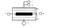
次に、前記ローラ基体の弾性層の表面にプラズマCVD法により被膜を形成する工程について図1に基づいて説明する。 Next, the process of forming a film on the surface of the elastic layer of the roller base by plasma CVD will be described with reference to FIG.
<<工程(1)>>
先ず、高周波プラズマCVD装置を用意する。この高周波プラズマCVD装置は、図1に示した通り、チャンバー7を備える。チャンバー7には、原料ガス供給部1、希ガス供給部2、一組の平板電極(第1の平板電極301、第2の平板電極303)、第1の平板電極301に接続された高周波電源4、減圧装置5、回転装置6が取り付けられている。第1及び第2の平板電極301、303は互いに平行に配置されている。平板電極301、303の形状は、特に限定されないが、通常、長方形が好ましい。これら平板電極の間には、回転装置6に接続した状態でローラ基体8が取り付けられる。ローラ基体8は、通常、その回転軸を、平板電極の電極の間の中央位置に、また、平板電極の表面と平行に配置することが好ましい。また、複数の基体を配置する場合は、平板電極と各基体の距離がそれぞれ等しくなる様に配置することが好ましい。前記の平板電極の一方には高周波電源4が接続されている。前記一組の平板電極には必要に応じて水、空気、液体窒素などを使用した冷却手段を設けても良い。
<< Step (1) >>
First, a high frequency plasma CVD apparatus is prepared. This high-frequency plasma CVD apparatus includes a
上記、高周波プラズマCVD装置で使用する高周波電源の周波数はプラズマ放電が可能であれば、特に限定されないが、0.1KHz〜5.0GHz、特には13.56MHz〜108MHzの範囲の周波数とすることが好ましい。この範囲内であると、チャンバー内で発生するプラズマの状態が安定するため、より均一な被膜を形成することができる。 The frequency of the high-frequency power source used in the above-described high-frequency plasma CVD apparatus is not particularly limited as long as plasma discharge is possible. However, the frequency may be in the range of 0.1 KHz to 5.0 GHz, particularly 13.56 MHz to 108 MHz. preferable. Within this range, the state of the plasma generated in the chamber is stabilized, so that a more uniform film can be formed.
次いで、平板電極301及び平板電極303の間にローラ基体8を回転可能に配置する。このとき、電力が印加される第1の平板電極301とローラ基体8の弾性層の表面との距離を20mm以上、100mm以下とする。この距離が20mmよりも小さいと被膜が不均一となることがあり、100mmよりも大きいと被膜の形成性が低下し、染み出しなどが発生する場合がある。
Next, the
<<工程(2)>>
チャンバー7の内部に圧力が13.3Pa以上、666.6Pa以下となるように原料ガスを導入する。原料ガスの圧力を上記の範囲内とすることにより、他の条件との関連において、チャンバー内でプラズマが安定に発生する。その結果、均一な被膜を弾性層上に形成することができる。
<< Step (2) >>
The source gas is introduced into the
<<工程(3)>>
ローラ基体8の被処理面(被膜が形成される面)の周速が6mm/秒以上、170mm/秒以下となるようにローラ基体を回転させつつ、出力0.3W/cm2以上、2.0W/cm2以下の電力を第1の平板電極301に印加する。そしてチャンバー7の内部にプラズマを発生させて弾性層10の表面に被膜を形成する。
<< Step (3) >>
1. Output 0.3 W / cm 2 or more while rotating the roller base so that the peripheral speed of the surface to be treated (surface on which the film is formed) of the
このように、本発明における被膜の形成は、所謂、高周波プラズマCVD(気相成長)法により行われる。高周波プラズマCVD法とは、原料ガスを高周波によってプラズマ化することで原料ガスをラジカル化し、該ラジカルを反応させて安定化し、処理面上に反応生成物からなる被膜を堆積させるプロセスを有する方法である。 Thus, the formation of the film in the present invention is performed by a so-called high-frequency plasma CVD (vapor phase growth) method. The high-frequency plasma CVD method is a method having a process of radicalizing a raw material gas by converting the raw material gas into high-frequency plasma, reacting and stabilizing the radical, and depositing a film made of a reaction product on the processing surface. is there.
原料ガスのプラズマ化は、グロー放電によって実現される。このグロー放電の方式によって、直流グロー放電を利用する方法、高周波グロー放電を利用する方法、マイクロ波放電を利用する方法などが知られている。本発明は高周波グロー放電を利用するものである。プラズマCVD法は、高速電子による原料ガスの分解を利用するため、生成エネルギーの大きな原料ガスを解離することができる。生成したプラズマは、電子温度とガス温度が異なる熱的非平衡状態にあり、ローラ基体の処理面の温度が低くても比較的均一な被膜を形成することができるという利点を有する。 The source gas is turned into plasma by glow discharge. A method using a direct current glow discharge, a method using a high frequency glow discharge, a method using a microwave discharge, and the like are known according to the glow discharge method. The present invention utilizes high frequency glow discharge. Since the plasma CVD method utilizes the decomposition of the source gas by high-speed electrons, the source gas having a large generation energy can be dissociated. The generated plasma is in a thermal non-equilibrium state in which the electron temperature and the gas temperature are different, and has an advantage that a relatively uniform film can be formed even if the temperature of the processing surface of the roller base is low.
本発明における平板電極の単位面積あたりの出力は0.3W/cm2以上、2.0W/cm2以下である。この出力が0.3W/cm2よりも小さいとプラズマ状態が不安定となり、被膜にムラが生じ、を引き起こす恐れがある。一方、この出力が2.0W/cm2よりも大きいとローラ基体表面への損傷が発生し変形が生じてしまい、寸法の安定性、外径の精度が低下することがある。なお、本発明における電極の面積とは平行におかれた平板電極一組の合計面積を意味する。本発明における一組の電極は、両者が同一の面積であることが好ましい。 Output per unit area of the plate electrode in the present invention is 0.3 W / cm 2 or more and 2.0 W / cm 2 or less. If this output is less than 0.3 W / cm 2 , the plasma state becomes unstable, and the coating film may become uneven, which may cause a problem. On the other hand, when the output is larger than 2.0 W / cm 2 , the roller base surface is damaged and deformed, and the dimensional stability and the outer diameter accuracy may be lowered. In addition, the area of the electrode in the present invention means the total area of a set of flat plate electrodes placed in parallel. The pair of electrodes in the present invention preferably have the same area.
本発明におけるローラ基体に被膜を形成する際の処理面の周速は6mm/s以上、170mm/s以下となるように、ローラ基体を回転する。処理面の周速が6mm/sよりも小さいと被膜の厚みが不均一となり、170mm/sよりも大きいと弾性層外周への慣性が大きくなることにより、ローラ基体が変形し、寸法安定性や外径の精度が低減することがある。 In the present invention, the roller base is rotated so that the peripheral speed of the treatment surface when forming a coating on the roller base is 6 mm / s or more and 170 mm / s or less. When the peripheral speed of the treated surface is less than 6 mm / s, the thickness of the coating becomes non-uniform, and when it exceeds 170 mm / s, the inertia to the outer periphery of the elastic layer increases, thereby deforming the roller base, resulting in dimensional stability and The accuracy of the outer diameter may be reduced.
上記高周波プラズマCVD装置で使用する原料ガスとしては、例えば以下のものが挙げられる。ガス化し得る水素化硅素(シラン類)(SiH4等);ハロゲンで置換されたシラン誘導体(SiH2Cl2、SiH2F2等);ハロゲン化硅素(SiF4、Si2F6、SiC14、SiBr4等);シロキサン類(ヘキサメチルジシロキサン等);ボラン類(B2H6等);ハロゲンガス(フッ素、塩素、臭素、ヨウ素等);ハロゲン化合物(BrF、ClF、ClF5、BrF5、IBr等);水素ガス;ハロゲン化水素(HF、HCl、HBr、HI等);ガス状態の又はガス化しうる炭化水素化合物(CH4、C2H6、C3H8、C4H10、C2H2、C6H6等);ハロゲン化物(CF4等)等。
Examples of the source gas used in the high-frequency plasma CVD apparatus include the following. Hydrogenated silicon hydrides (silanes) (SiH 4 etc.); halogen substituted silane derivatives (SiH 2 Cl 2 , SiH 2 F 2 etc.); silicon halides (SiF 4 , Si 2 F 6 , SiC1 4) , SiBr 4 etc.); siloxanes (hexamethyldisiloxane etc.); boranes (B 2 H 6 etc.); halogen gases (fluorine, chlorine, bromine, iodine etc.); halogen compounds (BrF, ClF, ClF 5 , BrF) 5, IBr, etc.); a hydrogen gas; hydrogen halide (HF, HCl, HBr, HI and the like); hydrocarbon compounds which may or gasification of gaseous state (CH 4, C 2 H 6 , C 3
本発明における被膜はこれらの原料ガスを使用して製膜される被膜である。好ましい被膜としては、SiOxを主成分とするもの、ダイヤモンドライクカーボン(Diamond like Carbon(DLCと表すことがある))からなるもの、パーフルオロ系高分子などの含フッ素被膜などが挙げられる。 The coating in the present invention is a coating formed using these raw material gases. Preferred examples of the coating include those composed mainly of SiOx, those composed of diamond-like carbon (sometimes referred to as DLC), and fluorine-containing coatings such as perfluoro polymers.
ここでSiOxからなる被膜とは、以下の条件を満たす被膜を指す:
・O―Si―Oを主骨格とすること;
・表面分析により全元素におけるSiとOの占める割合が60%以上であること;
・さらにはSi−O、及びSi―Cの化学結合を有し、かつSiとOの存在比率のO/Siが1.00以上、1.95以下、SiとCの存在比率のC/Siが0.05以上、1.00以下であること。
Here, the film made of SiOx refers to a film satisfying the following conditions:
・ O-Si-O as the main skeleton;
-The proportion of Si and O in all elements is 60% or more by surface analysis;
-Furthermore, it has a chemical bond of Si-O and Si-C, and O / Si of the abundance ratio of Si and O is 1.00 or more and 1.95 or less, C / Si of the abundance ratio of Si and C Is 0.05 or more and 1.00 or less.
DLCは、高硬度、電気絶縁性、赤外線透過性などを持つカーボンの総称である。具体的には、炭素を主骨格とし、かつ若干の水素を含有し,ダイヤモンド結合(SP3結合)とグラファイト結合(SP2結合)の両方の結合が混在しているアモルファス構造のカーボンを意味する。 DLC is a general term for carbon having high hardness, electrical insulation, infrared transmission, and the like. Specifically, it means carbon having an amorphous structure having carbon as a main skeleton, containing some hydrogen, and having both diamond bonds (SP 3 bonds) and graphite bonds (SP 2 bonds). .
被膜の厚みとしては、弾性層を磨耗から保護し、弾性層からの染み出しを低減する観点から15nm以上、5000nm以下が好ましく、染み出し防止性の観点からさらに好ましくは300nm以上、3000nm以下である。被膜の厚みを15nm以上とすると被膜が十分に形成され、容易に均一な被膜を形成することができる。また、厚みを5000nm以下とすると被膜形成時間が短縮され生産性が向上し、被膜の剛性が好適な範囲となる。 The thickness of the coating is preferably 15 nm or more and 5000 nm or less from the viewpoint of protecting the elastic layer from abrasion and reducing seepage from the elastic layer, and more preferably 300 nm or more and 3000 nm or less from the viewpoint of preventing bleeding. . When the thickness of the coating is 15 nm or more, the coating is sufficiently formed and a uniform coating can be easily formed. On the other hand, when the thickness is 5000 nm or less, the film formation time is shortened, the productivity is improved, and the rigidity of the film is in a suitable range.
以上のような材料、導電性物質を使用して製造された現像ローラは、体積抵抗率が、1×10⁴Ω・cm以上、1×10¹⁴Ω・cm以下であることが好ましい。現像ローラの体積抵抗率を1×10⁴Ω・cm以上とすると電流のリークに起因する画像不良を容易に防ぐことができる。また、体積抵抗率を1×10¹⁴Ω・cm以上とするとベタ画像の濃度不足などの画像不良の発生を抑えることができる。 The developing roller manufactured using the above materials and conductive materials preferably has a volume resistivity of 1 × 10 4 Ω · cm or more and 1 × 10 14 Ω · cm or less. When the volume resistivity of the developing roller is 1 × 10 4 Ω · cm or more, image defects caused by current leakage can be easily prevented. Further, when the volume resistivity is 1 × 10 14 Ω · cm or more, it is possible to suppress the occurrence of image defects such as insufficient density of a solid image.
次に上記本発明の製造方法によって得られた現像ローラを有する電子写真画像形成装置及び電子写真プロセスカートリッジについて図3を用いて説明する。図3は、本発明の製造方法によって得られた現像ローラを有する電子写真画像形成装置の一例の概略構成を示す断面図である。 Next, an electrophotographic image forming apparatus and an electrophotographic process cartridge having a developing roller obtained by the manufacturing method of the present invention will be described with reference to FIG. FIG. 3 is a cross-sectional view showing a schematic configuration of an example of an electrophotographic image forming apparatus having a developing roller obtained by the manufacturing method of the present invention.
上記電子写真画像形成装置においては、潜像担持体としての感光ドラム12が矢印方向に回転し、感光ドラム12を帯電処理するための帯電部材19によって一様に帯電される。そして、感光ドラム12に静電潜像を書き込む露光手段であるレーザー光18により、その表面に静電潜像が形成される。上記静電潜像は、感光ドラム12に対して接触配置される現像装置17によってトナー15を付与されることにより現像され、トナー像として可視化される。
In the electrophotographic image forming apparatus, the
現像は露光部にトナー像を形成するいわゆる反転現像を行っている。可視化された感光ドラム12上のトナー像は、転写部材である転写ローラ24によって記録媒体である紙29に転写される。トナー像を転写された紙29は、定着装置22により定着処理され、装置外に排紙されプリント動作が終了する。
Development is so-called reversal development in which a toner image is formed on the exposed portion. The visualized toner image on the
一方、転写されずに感光ドラム12上に残存した転写残トナーは、感光ドラム12表面をクリーニングするためのクリーニング部材であるクリーニングブレード21により掻き取られ廃トナー容器20に収納される。クリーニングされた感光ドラム12は上述作用を繰り返し行う。
On the other hand, the untransferred toner remaining on the
現像装置17は、一成分トナーとして非磁性トナーを収容した現像容器と、現像容器内の長手方向に延在する開口部に位置し感光ドラム12と対向設置されたトナー担持体としての現像ローラ13とを備えている。図3に示した電子写真画像形成装置においては、この現像ローラ13により感光ドラム12上の静電潜像を現像して可視化するようになっている。なお、図3において、27は、紙29を搬送するための転写搬送ベルトである。23、26及び28は各々、転写搬送ベルト27の回動に用いられる駆動ローラ、テンションローラ及び従動ローラである。25は、バイアス電源である。更に30は、不図示の給紙カセットから紙29を給紙する給紙ローラである。また、31は、給紙ローラ30により給紙された紙29を吸着して転写搬送ベルト27に担持させるための吸着ローラである。
The developing
図4は、本発明の製造方法によって得られた現像ローラを有する電子写真プロセスカートリッジの一例の概略構成を示す断面図である。図4に示した電子写真プロセスカートリッジは、現像ローラ13と規制ブレード16とを備えた現像装置17を有している。かつ、少なくともトナー塗布部材14と帯電部材19とを有しており、これらが一体的に保持されてなるものであり、電子写真画像形成装置に着脱可能に設けられる。
FIG. 4 is a cross-sectional view showing a schematic configuration of an example of an electrophotographic process cartridge having a developing roller obtained by the manufacturing method of the present invention. The electrophotographic process cartridge shown in FIG. 4 has a developing
トナー塗布部材14の構造としては、発泡骨格状スポンジ構造や軸芯体上にレーヨン、ポリアミド等の繊維を植毛したファーブラシ構造のものが、現像ローラ13へのトナー供給および未現像トナーの剥ぎ取りの点から好ましい。例えば、軸芯体上にポリウレタンフォームを設けた弾性ローラをトナー塗布部材14として用いることができる。
As the structure of the
以下、実施例によりさらに本発明を詳細に説明するが、本発明はこれらにより何ら限定されるものではない。 EXAMPLES Hereinafter, although an Example demonstrates this invention further in detail, this invention is not limited at all by these.
本実施例において得られたローラ基体の弾性層の厚み、弾性層の引張弾性率および線膨張率の測定並びに本実施例において得られた現像ローラの被膜の厚みの測定、被膜形成性、寸法安定性及び被膜表面の成分分析は次のようにして行った。 Measurement of the elastic layer thickness of the roller substrate obtained in this example, tensile elastic modulus and linear expansion coefficient of the elastic layer, measurement of the film thickness of the developing roller obtained in this example, film formability, dimensional stability The analysis of the property and the component of the coating surface was performed as follows.
<弾性層の厚み>
本実施例におけるロ−ラ基体の弾性層の厚みは、次のようにして測定した。
<Thickness of elastic layer>
The thickness of the elastic layer of the roller substrate in this example was measured as follows.
ザイザックスRVF600A(商品名、東京精密社製)にてローラ基体と導電性軸芯体の半径差を弾性層の厚みとして測定した。 The difference in radius between the roller base and the conductive shaft core was measured as the thickness of the elastic layer with ZAYAX RVF600A (trade name, manufactured by Tokyo Seimitsu Co., Ltd.).
<弾性層の引張弾性率>
本実施例におけるローラ基体の弾性層の引張弾性率は、JIS−K−7113に記載の方法に準じて測定した。引張試験機はテンシロンRTC−1250A(商品名、オリエンテック社製)を使用した。本実施例にて得られたローラ基体から、図5(a)に示す形状を有する長さ100mm、ローラ半周分の弾性層をサンプリングして被験試料とした。被験試料の両端各10mmを上記引張試験機のチャックへ取り付けた。チャック間の長さ80mm、測定速度20mm/分の条件で、測定環境を温度20℃、相対湿度50%とし引張弾性率を求めた。5回の測定を行い、得られた引張弾性率の平均値を弾性層の引張弾性率とした。
<Tensile modulus of elastic layer>
The tensile elastic modulus of the elastic layer of the roller base in this example was measured according to the method described in JIS-K-7113. Tensilon RTC-1250A (trade name, manufactured by Orientec Co., Ltd.) was used as the tensile tester. From the roller base body obtained in this example, an elastic layer having a shape shown in FIG. 5A having a length of 100 mm and a half circumference of the roller was sampled and used as a test sample. 10 mm of each end of the test sample was attached to the chuck of the tensile tester. The tensile elastic modulus was determined under the conditions of a length between chucks of 80 mm and a measurement speed of 20 mm / min, a measurement environment of 20 ° C. and a relative humidity of 50%. Measurement was performed five times, and the average value of the obtained tensile elastic moduli was defined as the tensile elastic modulus of the elastic layer.
<弾性層の線膨張率>
本実施例にて得られたローラ基体の弾性層の線膨張率は次のようにして測定した。
<Linear expansion coefficient of elastic layer>
The linear expansion coefficient of the elastic layer of the roller base obtained in this example was measured as follows.
本実施例にて得られたローラ基体から、図5(b)に示す形状を有する長さ20mm、ローラ全周分の弾性層を繰り抜き取って被験試料とした。この被験試料を熱機械分析装置TMA−60(商品名、島津製作所製)に取り付け、窒素雰囲気下に昇温速度5℃/minで23℃から50℃まで昇温し、得られた熱線膨張曲線から線膨張率を求めた。なお、測定は5回行い、その平均値を弾性層の線膨張率とした。 From the roller base obtained in this example, an elastic layer having a shape shown in FIG. 5B having a length of 20 mm and the entire circumference of the roller was drawn out to be used as a test sample. This test sample was attached to a thermomechanical analyzer TMA-60 (trade name, manufactured by Shimadzu Corporation), heated from 23 ° C. to 50 ° C. at a temperature rising rate of 5 ° C./min in a nitrogen atmosphere, and the obtained thermal linear expansion curve From the above, the linear expansion coefficient was obtained. The measurement was performed 5 times, and the average value was taken as the coefficient of linear expansion of the elastic layer.
<被膜の厚み・被膜形成性>
本実施例にて得られた現像ローラの被膜の厚みは次のようにして測定した。
<Thickness of film / film formability>
The film thickness of the developing roller obtained in this example was measured as follows.
本実施例にて得られた現像ローラの被膜の厚みは、薄膜測定装置F20−EXR(商品名、FILMETRICS社製)にて測定した。現像ローラの長手方向で等分された3箇所、周方向で等分された3箇所、合計9箇所における被膜の厚みを、温度20℃、相対湿度50%の環境下で測定し、得られた値の平均値を被膜の厚みとした。また、被膜の形成状態をデジタルマイクロスコープVHX−500(商品名、キーエンス社製)にて観察し、被覆状態を観察し、被覆面積を求め、被膜の形成性は以下の基準にて評価した。
5:被膜が形成されており、膜厚のバラツキは最大値/最小値が10%以下である。
4:被膜が形成されており、膜厚のバラツキは最大値/最小値が20%以下である。
3:被膜が形成されており、膜厚のバラツキは最大値/最小値が30%以下である。
2:被膜が形成されているが、被膜が平滑ではなく凹凸があり、膜厚のバラツキは最大値/最小値が30%よりも大きい。
1:被膜が形成されておらず、現像ローラの表面積の10%以上の範囲は膜で覆われていない。
The film thickness of the developing roller obtained in this example was measured with a thin film measuring apparatus F20-EXR (trade name, manufactured by FILMETRICS). It was obtained by measuring the thickness of the coating film at 9 places in total, 3 places equally divided in the longitudinal direction of the developing roller and 3 places equally divided in the circumferential direction in an environment of a temperature of 20 ° C. and a relative humidity of 50%. The average value was taken as the thickness of the coating. Moreover, the formation state of the film was observed with a digital microscope VHX-500 (trade name, manufactured by Keyence Corporation), the covering state was observed, the covering area was determined, and the film forming property was evaluated according to the following criteria.
5: A film is formed, and the maximum / minimum value of the variation in film thickness is 10% or less.
4: A film is formed, and the maximum / minimum value of the variation in film thickness is 20% or less.
3: A film is formed, and the maximum / minimum value of the variation in film thickness is 30% or less.
2: Although a film is formed, the film is not smooth and has irregularities, and the variation in film thickness has a maximum value / minimum value larger than 30%.
1: No film is formed, and a range of 10% or more of the surface area of the developing roller is not covered with the film.
<被膜表面の成分分析>
本実施例にて得られた現像ローラの被膜表面の成分分析は、X線光電子分光装置Quantum2000(商品名、アルバック・ファイ社製)にて行った。X線源としてALKαを用い、元素の存在比率O/Si及びC/Siを求めた。
<Component analysis of coating surface>
Component analysis of the coating roller surface obtained in this example was performed with an X-ray photoelectron spectrometer Quantum 2000 (trade name, manufactured by ULVAC-PHI). Using ALKα as the X-ray source, the abundance ratios of elements O / Si and C / Si were determined.
本実施例にて得られた現像ローラについて下記の評価を行った。 The following evaluation was performed on the developing roller obtained in this example.
<寸法安定性>
本実施例にて得られた現像ローラの形状の真円度・振れを以下の方法にて測定し、評価した。なお、測定環境は温度20℃、相対湿度60%とした。
<Dimensional stability>
The roundness and runout of the shape of the developing roller obtained in this example were measured and evaluated by the following methods. The measurement environment was a temperature of 20 ° C. and a relative humidity of 60%.
<<真円度>>
真円度については、真円度・円筒形状測定機「ラウンドテストRA−726」(商品名、ミツトヨ社製)を用いて100本の現像ローラを測定し、その平均値を真円度とした。
5:真円度最大値−真円度最小値が10μm以下で、極めて優れており現像ローラの真円度として最適である。
4:真円度最大値−真円度最小値が10μmより大きく、20μm以下で良好であり実用上問題がない。
3:真円度最大値−真円度最小値が20μmより大きく、30μm以下で現像ローラとして使用可能なレベルである。
2:真円度最大値−真円度最小値が30μmより大きく、40μmより小さく現像ローラとして実用上問題がある。
1:真円度最大値−真円度最小値が40μm以上で現像ローラとして使用が困難である。
<< Roundness >>
As for roundness, 100 developing rollers were measured using a roundness / cylindrical shape measuring machine “Round Test RA-726” (trade name, manufactured by Mitutoyo Corporation), and the average value was defined as roundness. .
5: roundness maximum value−roundness minimum value is 10 μm or less, which is extremely excellent, and is optimal as the roundness of the developing roller.
4: Maximum roundness value-minimum roundness value is greater than 10 μm and good at 20 μm or less, and there is no practical problem.
3: Maximum roundness value-minimum roundness value is a level that is larger than 20 μm and 30 μm or less and can be used as a developing roller.
2: Maximum roundness-minimum roundness is larger than 30 μm and smaller than 40 μm, and there is a practical problem as a developing roller.
1: Roundness maximum value−roundness minimum value is 40 μm or more, and it is difficult to use as a developing roller.
<<振れ>>
振れについては外径・振れ測定機「レーザースキャンマイクロメーター」(商品名、ミツトヨ社製)を用いて、振れの値の中において長手方向でもっとも大きな値をそのローラの振れとし、100本計測した値を平均し、振れとした。
5:振れが20μm以下で、極めて優れており現像ローラとして最適である。
4:振れが20μmより大きく、30μm以下で良好であり実用上問題がない。
3:振れが30μmより大きく、40μm以下で現像ローラとして使用可能なレベルである。
2:振れが40μmより大きく、45μm以下で実用上問題がある。
1:振れが45μmよりも大きく現像ローラとして使用が困難。
<< Runout >>
As for the runout, an outer diameter / runout measuring device “Laser Scan Micrometer” (trade name, manufactured by Mitutoyo Corporation) was used, and 100 runouts were measured with the largest runout value in the longitudinal direction as the runout of the roller. The values were averaged and taken as runout.
5: The runout is 20 μm or less, which is extremely excellent and optimal as a developing roller.
4: The deflection is larger than 20 μm and good at 30 μm or less, and there is no practical problem.
3: At a level where the runout is larger than 30 μm and 40 μm or less, it can be used as a developing roller.
2: There is a practical problem when the deflection is larger than 40 μm and 45 μm or less.
1: Larger than 45 μm and difficult to use as a developing roller.
原材料について、本実施例において特に記載が無い場合、市販の高純度品を使用した。 For raw materials, commercially available high-purity products were used unless otherwise specified in this example.
[実施例1]
(弾性層の作製)
下記の材料を上記原材料を直径(D)30mm、長さ(L)960mm、L/D=32の2軸押出機にて混練し、熱可塑性樹脂組成物のペレットを調製した。
・熱可塑性樹脂(動的架橋熱可塑性樹脂(TPVと表す)(商品名:サントプレーン8211−35;エーイーエスジャパン社製)):100質量部、
・プロセスオイル(商品名:PW380;出光興産社製):30質量部、
・導電剤(MTカーボンブラック(商品名:Thermax Floform N990;CANCARB社製)):30質量部。
[Example 1]
(Production of elastic layer)
The following raw materials were kneaded with a twin screw extruder having a diameter (D) of 30 mm, a length (L) of 960 mm, and L / D = 32 to prepare pellets of a thermoplastic resin composition.
Thermoplastic resin (dynamically cross-linked thermoplastic resin (represented as TPV) (trade name: Santoprene 8211-35; manufactured by AES Japan)): 100 parts by mass,
Process oil (trade name: PW380; manufactured by Idemitsu Kosan Co., Ltd.): 30 parts by mass
Conductive agent (MT carbon black (trade name: Thermax Floor N990; manufactured by CANCARB)): 30 parts by mass.
クロスヘッドに接続した押出成形機(商品名:ケムロック459X;ロード社製)を用いて上記のペレットを熔融押出しし、プライマー処理を施した導電性軸芯体(SUM製、直径6mm、長さ240mm)の外周面上に弾性層を形成した。両端部の弾性層を切断して取り除き、両端部に軸受部を設けた。これにより、軸芯体方向の弾性層部の長さを232mmとした後、該弾性層部を回転砥石で研磨し、直径12mm、厚みが3.0mmの弾性層を有するローラ基体を得た。 A conductive shaft core (made by SUM, diameter: 6 mm, length: 240 mm) obtained by melting and extruding the above pellets using an extrusion molding machine (trade name: Chemlock 459X; manufactured by Rhode) connected to a crosshead. The elastic layer was formed on the outer peripheral surface. The elastic layers at both ends were cut and removed, and bearings were provided at both ends. Thus, after the length of the elastic layer portion in the axial direction was 232 mm, the elastic layer portion was polished with a rotating grindstone to obtain a roller base having an elastic layer having a diameter of 12 mm and a thickness of 3.0 mm.
得られたローラ基体の弾性層の厚み、弾性層の引張弾性率および線膨張率を前記方法にて測定した。測定結果を表1に示す。 The thickness of the elastic layer of the obtained roller base, the tensile elastic modulus and the linear expansion coefficient of the elastic layer were measured by the above methods. The measurement results are shown in Table 1.
(被膜の作製)
図1に示した構成の高周波プラズマCVD装置を用意した。平板電極301及び303は、長さ(図1において左右方向の長さ)が300mm、幅20mmの長方形のステンレス(SUS316)製とした。これらの平板電極は、互いの間隔が112mmとなるように平行にチャンバー内に配置した。次いで、上記の方法で得られたローラ基体を、平板電極301と303との間に配置した。ここで、該ローラ基体の回転軸と該平板電極の表面とが平行となるように、かつ、該ローラ基体の被処理面と平板電極301との距離(電力印加側の電極表面とローラ基体処理面との最短距離)が50mmとなるように配置した。その後、真空ポンプを用いて該チャンバー内を1.0Paまで減圧した。次いで、ヘキサメチルジシロキサン蒸気1.0sccm、酸素1.5sccm及びアルゴンガス22.5sccmの混合ガスをチャンバー内に導入した。ここで「sccm」は、前記原料ガスが温度0℃、1気圧のときの毎分あたりの体積流量を表す(体積の単位はcm3)。チャンバー内の反応ガスの圧力は、25.3Paになるように調整した。
(Preparation of coating)
A high frequency plasma CVD apparatus having the configuration shown in FIG. 1 was prepared. The
チャンバー内の圧力が一定になった後、高周波電源により周波数13.56MHz、120wの電力を、平板電極301に印加し、出力1W/cm2の電力を投じて、平板電極301及び303の間にプラズマを発生させた。チャンバー内に設置したローラ基体は被処理面の周速が30mm/秒となるように回転させて、3分間処理を行った。処理が終了後、電力印加を停止し、チャンバー内に大気圧になるまで空気を導入し被膜が形成された現像ローラを取り出した。この現像ローラについて、上記した各種の評価を行った。
After the pressure in the chamber becomes constant, power of a frequency of 13.56 MHz and 120 w is applied to the
また、本実施例にかかる現像ローラの被膜表面の元素の原子数比O/Si及びC/Siを上記成分分析により求めたところ、それぞれ1.56及び0.32であり、被膜はSiOxであった。また、被膜の厚みは1000nmであった。被膜の成膜条件を表2に示す。また、得られた弾性ローラの評価結果を表3に示す。 Further, the atomic ratios O / Si and C / Si of the elements on the surface of the film of the developing roller according to this example were determined by the above component analysis, and were 1.56 and 0.32, respectively, and the film was SiOx. It was. The thickness of the coating was 1000 nm. Table 2 shows film forming conditions. Table 3 shows the evaluation results of the obtained elastic roller.
[実施例2]
導電剤の使用量を50質量部とし、さらに、充填剤としてタルクを50質量部使用した。それ以外は、実施例1と同様にしてローラ基体を作製し、該ローラ基体を用いて実施例1と同様にして現像ローラを作製した。弾性層の物性、被膜の成膜条件並びに得られた現像ローラの評価結果を表1〜3に示す。なお、被膜の厚みは1000nmであった。
[Example 2]
The amount of the conductive agent used was 50 parts by mass, and 50 parts by mass of talc was used as a filler. Other than that, a roller base was produced in the same manner as in Example 1, and a developing roller was produced in the same manner as in Example 1 using the roller base. Tables 1 to 3 show the physical properties of the elastic layer, the film formation conditions, and the evaluation results of the developing roller obtained. The thickness of the coating was 1000 nm.
[実施例3]
プロセスオイルの使用量を100質量部とした。それ以外は、実施例1と同様にしてローラ基体を作製し、該ローラ基体を用いて実施例1と同様にして現像ローラを作製した。弾性層の物性、被膜の成膜条件並びに得られた現像ローラの評価結果を表1〜3に示す。なお、被膜の厚みは1000nmであった。
[Example 3]
The amount of process oil used was 100 parts by mass. Other than that, a roller base was produced in the same manner as in Example 1, and a developing roller was produced in the same manner as in Example 1 using the roller base. Tables 1 to 3 show the physical properties of the elastic layer, the film formation conditions, and the evaluation results of the developing roller obtained. The thickness of the coating was 1000 nm.
[実施例4]
実施例1と同様にしてローラ基体を作製した。原料ガスとしてのヘキサメチルジシロキサン蒸気をトルエン蒸気に変え、アルゴンガスの導入量を24.0sccmに変えて被膜をDLC被膜とした。それ以外は実施例1と同様にして現像ローラを得た。弾性層の物性、被膜の成膜条件並びに得られた現像ローラの評価結果を表1〜3に示す。なお、被膜の厚みは1020nmであった。
[Example 4]
A roller base was produced in the same manner as in Example 1. Hexamethyldisiloxane vapor as a source gas was changed to toluene vapor, and the amount of argon gas introduced was changed to 24.0 sccm to form a DLC coating. Otherwise, a developing roller was obtained in the same manner as in Example 1. Tables 1 to 3 show the physical properties of the elastic layer, the film formation conditions, and the evaluation results of the developing roller obtained. The thickness of the coating was 1020 nm.
[実施例5]
下記の弾性層の原材料を10リットルニーダーで混練した後に、これに上記加硫促進剤及び加硫剤を添加して2本ロールを用いて混練し、ゴム組成物とした。
・ゴム(NBR(商品名:N235S;JSR社製;アクリロニトリル36wt%)):100質量部、
・導電剤(MTカーボンブラック(商品名:Thermax Floform N990;CANCARB社製)):50質量部、
・充填剤(酸化亜鉛):5質量部、
・加工助剤(ステアリン酸):1質量部、
・加硫剤(硫黄):1質量部、
・加硫促進剤(メルカプトベンゾチアゾール):1質量部。
[Example 5]
The raw material of the following elastic layer was kneaded with a 10 liter kneader, and then the above vulcanization accelerator and vulcanizing agent were added thereto and kneaded using two rolls to obtain a rubber composition.
Rubber (NBR (trade name: N235S; manufactured by JSR; acrylonitrile 36 wt%)): 100 parts by mass
Conductive agent (MT carbon black (trade name: Thermax Floor N990; manufactured by CANCARB)): 50 parts by mass,
Filler (zinc oxide): 5 parts by mass
Processing aid (stearic acid): 1 part by mass
・ Vulcanizing agent (sulfur): 1 part by mass,
-Vulcanization accelerator (mercaptobenzothiazole): 1 part by mass.
このゴム組成物を用いたこと以外は、実施例1と同様にしてローラ基体を作製し、当該ローラ基体を用いて実施例1と同様にして現像ローラを得た。弾性層の物性、被膜の成膜条件並びに得られた現像ローラの評価結果を表1〜3に示す。被膜の厚みは1000nmであった。 A roller base was produced in the same manner as in Example 1 except that this rubber composition was used, and a developing roller was obtained in the same manner as in Example 1 using the roller base. Tables 1 to 3 show the physical properties of the elastic layer, the film formation conditions, and the evaluation results of the developing roller obtained. The thickness of the coating was 1000 nm.
[実施例6]
熱可塑性樹脂をエチレン酢酸ビニル共重合樹脂(EV170(商品名、三井デュポンポリケミカル社製))(表1中においてEVAと表示した)に変えた。それ以外は実施例1と同様にしてローラ基体を作製し、当該ローラ基体を用いて実施例1と同様にして現像ローラを得た。弾性層の物性、被膜の成膜条件並びに得られた現像ローラの評価結果を表1〜3に示す。被膜の厚みは1000nmであった。
[Example 6]
The thermoplastic resin was changed to an ethylene vinyl acetate copolymer resin (EV170 (trade name, manufactured by Mitsui DuPont Polychemical)) (shown as EVA in Table 1). Otherwise, a roller base was produced in the same manner as in Example 1, and a developing roller was obtained in the same manner as in Example 1 using the roller base. Tables 1 to 3 show the physical properties of the elastic layer, the film formation conditions, and the evaluation results of the developing roller obtained. The thickness of the coating was 1000 nm.
[実施例7]
導電性軸芯体を直径11.0mmの導電性軸芯体に変え、弾性層の厚みを0.5mmとした以外は実施例1と同様にしてローラ基体を作製し、当該ローラ基体を用いて実施例1と同様にして現像ローラを得た。弾性層の物性、被膜の成膜条件並びに得られた現像ローラの評価結果を表1〜3に示す。被膜の厚みは1000nmであった。
[Example 7]
A roller base was prepared in the same manner as in Example 1 except that the conductive shaft core was changed to a conductive shaft core having a diameter of 11.0 mm and the thickness of the elastic layer was 0.5 mm. A developing roller was obtained in the same manner as in Example 1. Tables 1 to 3 show the physical properties of the elastic layer, the film formation conditions, and the evaluation results of the developing roller obtained. The thickness of the coating was 1000 nm.
[実施例8]
導電性軸芯体を直径2.0mmの導電性軸芯体に変え、弾性層の厚みを5.0mmとした以外は実施例1と同様にしてローラ基体を作製し、当該ローラ基体を用いて実施例1と同様にして現像ローラを得た。弾性層の物性、被膜の成膜条件並びに得られた現像ローラの評価結果を表1〜3に示す。被膜の厚みは1000nmであった。
[Example 8]
A roller base is prepared in the same manner as in Example 1 except that the conductive shaft core is changed to a conductive shaft core having a diameter of 2.0 mm and the thickness of the elastic layer is 5.0 mm. A developing roller was obtained in the same manner as in Example 1. Tables 1 to 3 show the physical properties of the elastic layer, the film formation conditions, and the evaluation results of the developing roller obtained. The thickness of the coating was 1000 nm.
[実施例9]
プロセスオイルの使用量を150質量部、導電剤の使用量を10質量部に変えた以外は実施例1と同様にしてローラ基体を作製し、当該ローラ基体を用いて実施例1と同様にして現像ローラを得た。弾性層の物性、被膜の成膜条件並びに得られた現像ローラの評価結果を表1〜3に示す。被膜の厚みは1000nmであった。
[Example 9]
A roller base was prepared in the same manner as in Example 1 except that the amount of process oil used was changed to 150 parts by mass and the amount of conductive agent used was changed to 10 parts by mass. A developing roller was obtained. Tables 1 to 3 show the physical properties of the elastic layer, the film formation conditions, and the evaluation results of the developing roller obtained. The thickness of the coating was 1000 nm.
[実施例10]
熱可塑性樹脂を動的架橋熱可塑性樹脂(TPVと表す)(サントプレーン8211−87(商品名)、エーイーエスジャパン社製)に変え、また、プロセスオイルの使用量を0質量部に変えた以外は実施例1と同様にしてローラ基体を作製した。そして、当該ローラ基体を用いて実施例1と同様にして現像ローラを得た。弾性層の物性、被膜の成膜条件並びに得られた現像ローラの評価結果を表1〜3に示す。被膜の厚みは1000nmであった。
[Example 10]
The thermoplastic resin was changed to a dynamically crosslinked thermoplastic resin (referred to as TPV) (Santoprene 8211-87 (trade name), manufactured by AES Japan), and the amount of process oil used was changed to 0 parts by mass. A roller base was prepared in the same manner as in Example 1. A developing roller was obtained in the same manner as in Example 1 using the roller base. Tables 1 to 3 show the physical properties of the elastic layer, the film formation conditions, and the evaluation results of the developing roller obtained. The thickness of the coating was 1000 nm.
[実施例11]
真空チャンバー内の反応ガスの圧力を13.3Paに変えた以外は実施例1と同様にして、現像ローラを得た。弾性層の物性、被膜の成膜条件並びに得られた現像ローラの評価結果を表1〜3に示す。被膜の厚みは800nmであった。
[Example 11]
A developing roller was obtained in the same manner as in Example 1 except that the pressure of the reaction gas in the vacuum chamber was changed to 13.3 Pa. Tables 1 to 3 show the physical properties of the elastic layer, the film formation conditions, and the evaluation results of the developing roller obtained. The thickness of the coating was 800 nm.
[実施例12]
真空チャンバー内の反応ガスの圧力を666.6Paに変えた以外は実施例1と同様にして現像ローラを得た。弾性層の物性、被膜の成膜条件並びに得られた現像ローラの評価結果を表1〜3に示す。被膜の厚みは1100nmであった。
[Example 12]
A developing roller was obtained in the same manner as in Example 1 except that the pressure of the reaction gas in the vacuum chamber was changed to 666.6 Pa. Tables 1 to 3 show the physical properties of the elastic layer, the film formation conditions, and the evaluation results of the developing roller obtained. The thickness of the coating was 1100 nm.
[実施例13]
ローラ基体の被処理面の周速を6.0mm/sとした以外は実施例1と同様にして現像ローラを得た。弾性層の物性、被膜の成膜条件並びに得られた現像ローラの評価結果を表1〜3に示す。被膜の厚みは1000nmであった。
[Example 13]
A developing roller was obtained in the same manner as in Example 1 except that the peripheral speed of the processing surface of the roller base was changed to 6.0 mm / s. Tables 1 to 3 show the physical properties of the elastic layer, the film formation conditions, and the evaluation results of the developing roller obtained. The thickness of the coating was 1000 nm.
[実施例14]
ローラ基体の被処理面の周速を170.0mm/sとした以外は実施例1と同様にして現像ローラを得た。弾性層の物性、被膜の成膜条件並びに得られた現像ローラの評価結果を表1〜3に示す。被膜の厚みは1000nmであった。
[Example 14]
A developing roller was obtained in the same manner as in Example 1 except that the peripheral speed of the surface to be processed of the roller base was 170.0 mm / s. Tables 1 to 3 show the physical properties of the elastic layer, the film formation conditions, and the evaluation results of the developing roller obtained. The thickness of the coating was 1000 nm.
[実施例15]
出力を0.3W/cm2となるように調整した以外は実施例1と同様にして現像ローラを得た。弾性層の物性、被膜の成膜条件並びに得られた現像ローラの評価結果を表1〜3に示す。被膜の厚みは800nmであった。
[Example 15]
A developing roller was obtained in the same manner as in Example 1 except that the output was adjusted to 0.3 W / cm 2 . Tables 1 to 3 show the physical properties of the elastic layer, the film formation conditions, and the evaluation results of the developing roller obtained. The thickness of the coating was 800 nm.
[実施例16]
出力を2.0w/cm2となるように調整した以外は実施例1と同様にして現像ローラを得た。弾性層の物性、被膜の成膜条件並びに得られた現像ローラの評価結果を表1〜3に示す。被膜の厚みは1100nmであった。
[Example 16]
A developing roller was obtained in the same manner as in Example 1 except that the output was adjusted to 2.0 w / cm 2 . Tables 1 to 3 show the physical properties of the elastic layer, the film formation conditions, and the evaluation results of the developing roller obtained. The thickness of the coating was 1100 nm.
[実施例17]
平板電極の間隔が52mmとなるように平行にチャンバー内に配置し、電極とローラ基体との距離を20mmに変えた以外は実施例1と同様にして現像ローラを得た。弾性層の物性、被膜の成膜条件並びに得られた現像ローラの評価結果を表1〜3に示す。被膜の厚みは1100nmであった。
[Example 17]
A developing roller was obtained in the same manner as in Example 1 except that the flat electrodes were placed in the chamber in parallel so that the distance between the electrodes was 52 mm, and the distance between the electrode and the roller base was changed to 20 mm. Tables 1 to 3 show the physical properties of the elastic layer, the film formation conditions, and the evaluation results of the developing roller obtained. The thickness of the coating was 1100 nm.
[実施例18]
平板電極の間隔が212mmとなるように平行にチャンバー内に配置し、電極とローラ基体との距離を100mmとした以外は実施例1と同様にして現像ローラを得た。弾性層の物性、被膜の成膜条件並びに得られた現像ローラの評価結果を表1〜3に示す。被膜の厚みは800nmであった。
[Example 18]
A developing roller was obtained in the same manner as in Example 1 except that the flat electrodes were arranged in the chamber in parallel so that the distance between them was 212 mm, and the distance between the electrode and the roller base was 100 mm. Tables 1 to 3 show the physical properties of the elastic layer, the film formation conditions, and the evaluation results of the developing roller obtained. The thickness of the coating was 800 nm.
[比較例1]
反応ガスの圧力を6.66Paとした以外は実施例1と同様にして現像ローラを得た。弾性層の物性、被膜の成膜条件並びに得られた現像ローラの評価結果を表1〜3に示す。被膜の厚みは700nmであった。
[Comparative Example 1]
A developing roller was obtained in the same manner as in Example 1 except that the pressure of the reaction gas was changed to 6.66 Pa. Tables 1 to 3 show the physical properties of the elastic layer, the film formation conditions, and the evaluation results of the developing roller obtained. The thickness of the coating was 700 nm.
[比較例2]
反応ガスの圧力を733.3Paに変えた以外は実施例1と同様にして現像ローラを得た。弾性層の物性、被膜の成膜条件並びに得られた現像ローラの評価結果を表1〜3に示す。被膜の厚みは1500nmであった。
[Comparative Example 2]
A developing roller was obtained in the same manner as in Example 1 except that the pressure of the reaction gas was changed to 733.3 Pa. Tables 1 to 3 show the physical properties of the elastic layer, the film formation conditions, and the evaluation results of the developing roller obtained. The thickness of the coating was 1500 nm.
[比較例3]
ローラ基体の被処理面の周速を5.0mm/sとした以外は実施例1と同様にして現像ローラを得た。弾性層の物性、被膜の成膜条件並びに得られた現像ローラの評価結果を表1〜3に示す。被膜の厚みは1000nmであった。
[Comparative Example 3]
A developing roller was obtained in the same manner as in Example 1 except that the peripheral speed of the processing surface of the roller base was set to 5.0 mm / s. Tables 1 to 3 show the physical properties of the elastic layer, the film formation conditions, and the evaluation results of the developing roller obtained. The thickness of the coating was 1000 nm.
[比較例4]
ローラ基体の被処理面の周速を180mm/sとした以外は実施例1と同様にして現像ローラを得た。弾性層の物性、被膜の成膜条件並びに得られた現像ローラの評価結果を表1〜3に示す。被膜の厚みは1000nmであった。
[Comparative Example 4]
A developing roller was obtained in the same manner as in Example 1 except that the peripheral speed of the surface to be processed of the roller base was 180 mm / s. Tables 1 to 3 show the physical properties of the elastic layer, the film formation conditions, and the evaluation results of the developing roller obtained. The thickness of the coating was 1000 nm.
[比較例5]
出力を0.2w/cm2とした以外は実施例1と同様にして現像ローラを得た。弾性層の物性、被膜の成膜条件並びに得られた現像ローラの評価結果を表1〜3に示す。被膜の厚みは600nmであった。
[Comparative Example 5]
A developing roller was obtained in the same manner as in Example 1 except that the output was 0.2 w / cm 2 . Tables 1 to 3 show the physical properties of the elastic layer, the film formation conditions, and the evaluation results of the developing roller obtained. The thickness of the coating was 600 nm.
[比較例6]
出力を2.5w/cm2とした以外は実施例1と同様にして現像ローラを得た。弾性層の物性、被膜の成膜条件並びに得られた現像ローラの評価結果を表1〜3に示す。被膜の厚みは1500nmであった。
[Comparative Example 6]
A developing roller was obtained in the same manner as in Example 1 except that the output was 2.5 w / cm 2 . Tables 1 to 3 show the physical properties of the elastic layer, the film formation conditions, and the evaluation results of the developing roller obtained. The thickness of the coating was 1500 nm.
[比較例7]
平板電極の間隔が42mmとなるように平行にチャンバー内に配置し、電極とローラ基体との距離を15mmとした以外は実施例1と同様にして現像ローラを得た。弾性層の物性、被膜の成膜条件並びに得られた現像ローラの評価結果を表1〜3に示す。被膜の厚みは1300nmであった。
[Comparative Example 7]
A developing roller was obtained in the same manner as in Example 1 except that the flat electrodes were placed in the chamber in parallel so that the distance between them was 42 mm, and the distance between the electrode and the roller base was 15 mm. Tables 1 to 3 show the physical properties of the elastic layer, the film formation conditions, and the evaluation results of the developing roller obtained. The thickness of the coating was 1300 nm.
[比較例8]
平板電極の間隔が232mmとなるように平行にチャンバー内に配置し、電極とローラ基体との距離を110mmとした以外は実施例1と同様にして現像ローラを得た。弾性層の物性、被膜の成膜条件並びに得られた現像ローラの評価結果を表1〜3に示す。被膜の厚みは600nmであった。
[Comparative Example 8]
A developing roller was obtained in the same manner as in Example 1 except that the flat electrodes were placed in parallel in the chamber so that the distance between the electrodes was 232 mm, and the distance between the electrode and the roller base was 110 mm. Tables 1 to 3 show the physical properties of the elastic layer, the film formation conditions, and the evaluation results of the developing roller obtained. The thickness of the coating was 600 nm.

次に、上記実施例1〜18に係る現像ローラを用いて以下の評価を行った。結果を表4に示す。 Next, the following evaluation was performed using the developing roller according to Examples 1 to 18 described above. The results are shown in Table 4.
[トナー劣化]
各実施例にて得られた現像ローラの各々を組み込んだ電子写真プロセスカートリッジ(商品名:CRG−311BLK;キヤノン株式会社製)を作製した。この電子写真プロセスカートリッジをカラーレーザープリンター(商品名:サテラLBP5400;キヤノン株式会社製)に搭載した。温度30℃、相対湿度80%の高温、高湿条件下で、A4サイズの用紙(商品名:キヤノンカラーレーザーコピアペーパー;坪量81.4g/m2、厚さ92μm、白色度92%)へ20ppmの印刷速度で1%印字物の画像を連続して3500枚印刷した。それに引き続いて全白画像を1枚印刷し、当該全白画像についてカブリの有無を目視で検査した。得られた結果に基づき、下記の基準でトナー劣化を評価した。
5:肉眼ではトナー劣化によるカブリを確認できなかった。
4:トナー劣化によるカブリが少なく画像上問題がないもの。
3:トナー劣化によるカブリが確認されるが実用可能なレベル。
2:トナー劣化によるカブリが確認され、実用上問題があるもの。
1:ひどいカブリが確認されトナー劣化が大きいもの。
[Toner deterioration]
An electrophotographic process cartridge (trade name: CRG-311BLK; manufactured by Canon Inc.) incorporating each of the developing rollers obtained in each example was produced. This electrophotographic process cartridge was mounted on a color laser printer (trade name: Satera LBP5400; manufactured by Canon Inc.). To A4 size paper (product name: Canon color laser copier paper; basis weight 81.4 g / m 2 , thickness 92 μm, whiteness 92%) under high temperature and high humidity conditions of 30 ° C. and 80% relative humidity 3500 images of 1% printed matter were continuously printed at a printing speed of 20 ppm. Subsequently, an all-white image was printed, and the entire white image was visually inspected for the presence of fog. Based on the obtained results, toner deterioration was evaluated according to the following criteria.
5: Fog due to toner deterioration could not be confirmed with the naked eye.
4: No fogging due to toner deterioration and no problem in image.
3: Fog due to toner deterioration is confirmed, but at a practical level.
2: Fog due to toner deterioration is confirmed, and there is a problem in practical use.
1: Severe fogging is confirmed and toner deterioration is large.
[セット性]
本実施例にて得られた現像ローラを電子写真プロセスカートリッジ(CRG−311BLK(商品名、キヤノン株式会社製))に組み込んだ。これを、過酷高温/高湿環境の恒温槽内(温度40℃、相対湿度95%)で30日放置した。この後に、温度20℃、相対湿度50%の環境へ移動し一日放置し、この電子写真プロセスカートリッジをカラーレーザープリンターLBP5400(商品名、キヤノン社製)本体に搭載しハーフトーン画像を印刷した。得られた画像を目視で検査し、圧接跡の画像への影響を下記の基準に基づき評価した。尚、ハーフトーン画像は濃度計(商品名:マクベスカラーチェッカーRD−1255;マクベス株式会社製)を用いた測定による濃度が0.7である画像を使用した。
5:圧接跡の画像不良無し。
4:圧接跡の画像不良が極めて薄く見受けられるが画像に影響なし。
3:圧接跡が薄く見られるが、実用上問題とならない程度の画像不良がある。
2:圧接跡が見られ、画像不良が見受けられ実用上問題がある。
1:圧接跡による画像に明らかな問題があり、実用できない。
[Setability]
The developing roller obtained in this example was incorporated into an electrophotographic process cartridge (CRG-311BLK (trade name, manufactured by Canon Inc.)). This was left for 30 days in a constant temperature bath (temperature 40 ° C., relative humidity 95%) in a severe high temperature / high humidity environment. Thereafter, the electrophotographic process cartridge was moved to an environment with a temperature of 20 ° C. and a relative humidity of 50% and allowed to stand for one day, and this electrophotographic process cartridge was mounted on a color laser printer LBP5400 (trade name, manufactured by Canon Inc.) to print a halftone image. The obtained image was visually inspected, and the influence of the press contact mark on the image was evaluated based on the following criteria. In addition, the halftone image used the image whose density | concentration by the measurement using a densitometer (brand name: Macbeth color checker RD-1255; Macbeth Co., Ltd.) is 0.7.
5: No image defect on the press contact mark.
4: The image defect of the press contact mark is very thin, but the image is not affected.
3: Although the pressure contact trace is seen thin, there is an image defect that does not cause a practical problem.
2: Pressure contact marks are seen, image defects are observed, and there are practical problems.
1: There is a clear problem in the image due to the pressure contact mark, and it cannot be put into practical use.
[画像評価]
本実施例にて得られた現像ローラを電子写真プロセスカートリッジ(CRG−311BLK(商品名、キヤノン株式会社製))に組み込んだ。これを、カラーレーザープリンターLBP5400(商品名、キヤノン社製)本体に搭載し、温度20℃、相対湿度50%の環境下で、非磁性一成分ブラックトナーで上記と同じハーフトーン画像を100枚出力した。得られた画像を目視にて検査し画像不良の有無を総合的に確認し実用性の判断を行い下記基準に基づき画像評価を行った。尚、ハーフトーン画像は濃度計マクベスカラーチェッカーRD−1255(商品名、マクベス株式会社製を用いた測定による濃度が0.7である画像を使用した。)
5:画像不良無し。
4:画像不良がほぼ見られない。
3:実用上問題とならない程度の画像不良がある。
2:画像不良が見受けられ実用上問題がある。
1:画像に明らかな問題があり、実用できない。
[Image evaluation]
The developing roller obtained in this example was incorporated into an electrophotographic process cartridge (CRG-311BLK (trade name, manufactured by Canon Inc.)). This is mounted on the main body of the color laser printer LBP5400 (trade name, manufactured by Canon Inc.) and outputs 100 halftone images as described above with non-magnetic one-component black toner in an environment of a temperature of 20 ° C. and a relative humidity of 50%. did. The obtained image was visually inspected to comprehensively confirm the presence or absence of an image defect, to determine practicality, and to evaluate the image based on the following criteria. The halftone image was a densitometer Macbeth Color Checker RD-1255 (trade name, an image having a density of 0.7 as measured by Macbeth Co., Ltd.).
5: No image defect.
4: Image defect is hardly seen.
3: There is an image defect that does not cause a practical problem.
2: An image defect is observed and there is a problem in practical use.
1: The image has a clear problem and cannot be put into practical use.
[染み出し]
本実施例にて得られた現像ローラを、温度40℃、相対湿度95%の環境試験機内に1ヶ月放置した後に、目視にて現像ローラ表面の染み出しを検査した。さらに該現像ローラを電子写真プロセスカートリッジ(商品名:CRG−311BLK;キヤノン株式会社製)に組み込んだ。これを、カラーレーザープリンター(商品名:LBP5400;キヤノン社製)の本体に装着し、温度20℃、相対湿度50%の環境下にて上記と同じハーフトーン画像を出力し、画像を目視にて検査し画像への影響を確認し以下の基準にて染み出しを評価した。尚、ハーフトーン画像は濃度計マクベスカラーチェッカーRD−1255(商品名、マクベス株式会社製を用いた測定による濃度が0.7である画像を使用した。)
5:現像ローラ表面に染み出しが無く、画像への影響も無い。
4:現像ローラ表面に僅かに染み出しがみられるが画像上何ら問題はない。
3:現像ローラ表面に染み出しがみられ、画像上にわずかに画像損失が見られるが実用上問題ない。
2:現像ローラ表面に染み出しがみられ、画像上に画像損失がみられ、実用上問題がある。
1:染み出しが非常に多く、実用不可。
[Exudation]
The developing roller obtained in this example was left in an environmental test machine at a temperature of 40 ° C. and a relative humidity of 95% for 1 month, and then the surface of the developing roller was visually inspected. Further, the developing roller was incorporated into an electrophotographic process cartridge (trade name: CRG-311BLK; manufactured by Canon Inc.). This is mounted on the main body of a color laser printer (trade name: LBP5400; manufactured by Canon Inc.), and the same halftone image as above is output under an environment of a temperature of 20 ° C. and a relative humidity of 50%. Inspection and the effect on the image were confirmed, and exudation was evaluated according to the following criteria. The halftone image was a densitometer Macbeth Color Checker RD-1255 (trade name, an image having a density of 0.7 as measured by Macbeth Co., Ltd.).
5: There is no bleeding on the surface of the developing roller, and there is no influence on the image.
4: Slight oozing is observed on the surface of the developing roller, but there is no problem on the image.
3: Exudation is observed on the surface of the developing roller, and a slight image loss is observed on the image, but there is no practical problem.
2: Exudation is observed on the surface of the developing roller, image loss is observed on the image, and there is a problem in practical use.
1: Exudation is very large and not practical.
これらの結果から、実施例1〜18に係るローラ部材の被膜が、現像ローラとしての実使用に十分に耐え得る性能を有していることが分った。 From these results, it was found that the coating film of the roller member according to Examples 1 to 18 has a performance that can sufficiently withstand actual use as a developing roller.
1 原料ガス供給部
2 希ガス供給部
301、303 平板電極
4 高周波電源
5 減圧装置
6 回転装置
7 真空チャンバー
8 ローラ基体
9 導電性軸芯体
10 弾性層
11 被膜
12 感光ドラム
13 現像ローラ
14 トナー塗布部材
15 トナー
16 規制ブレード
17 現像装置
18 レーザー光
19 帯電部材
20 廃トナー容器
21 クリーニングブレード
22 定着装置
23 駆動ローラ
24 転写ローラ
25 バイアス電源
26 テンションローラ
27 転写搬送ベルト
28 従動ローラ
29 紙
30 給紙ローラ
31 吸着ローラ
32 引張弾性率測定用被験試料
33 線膨張率測定用被験試料
DESCRIPTION OF
Claims (5)
該工程は、
(1)チャンバーの内部に平行に配置した第1及び第2の平板電極の間に、前記弾性層の表面と前記各平板電極との距離がそれぞれ20mm以上、100mm以下となるように配置する工程と、
(2)前記チャンバー内に圧力が13.3Pa以上、666.6Pa以下となるように原料ガスを導入する工程と、
(3)前記原料ガスを導入したチャンバー内で前記ローラ基体を、被処理面の周速が6mm/s以上、170mm/s以下となるように回転させつつ、出力0.3W/cm2以上、2.0W/cm2以下の電力を前記第1の平板電極に印加して該チャンバー内にプラズマを発生させ、前記弾性層の表面に被膜を形成する工程と、
を含み、
前記被膜が、SiOxを主成分とするものであることを特徴とする電子写真用ローラ部材の製造方法。 The elastic layer of the roller base having a conductive shaft core and an elastic layer having a thickness of 0.5 mm or more and 5.0 mm or less formed on the outer peripheral surface and a tensile elastic modulus of 1 MPa or more and 100 MPa or less. An electrophotographic roller member manufacturing method comprising a step of forming a film on the outer peripheral surface by a plasma CVD method,
The process
(1) The process of arrange | positioning between the 1st and 2nd flat plate electrode arrange | positioned in parallel with the inside of a chamber so that the distance of the surface of the said elastic layer and each said flat plate electrode may be 20 mm or more and 100 mm or less, respectively. When,
(2) introducing a source gas so that the pressure is 13.3 Pa or more and 666.6 Pa or less in the chamber;
(3) While rotating the roller base so that the peripheral speed of the surface to be processed is 6 mm / s or more and 170 mm / s or less in the chamber into which the source gas is introduced, the output is 0.3 W / cm 2 or more, Applying a power of 2.0 W / cm 2 or less to the first plate electrode to generate plasma in the chamber, and forming a coating on the surface of the elastic layer;
Only including,
The method for producing a roller member for electrophotography , wherein the coating is mainly composed of SiOx .
・O―Si―Oを主骨格として有すること、
・該被膜の表面分析により、全元素におけるSiとOの占める割合が60%以上であること、
・Si−O、及びSi―Cの化学結合を有し、SiとOの存在比率(O/Si)が1.00以上、1.95以下であり、かつ、SiとCの存在比率(C/Si)が0.05以上、1.00以下であること。 The method for producing a roller member for electrophotography according to claim 1 or 2 , wherein the coating satisfies the following conditions:
-Having O-Si-O as the main skeleton,
-According to the surface analysis of the coating, the proportion of Si and O in all elements is 60% or more,
-It has a chemical bond of Si-O and Si-C, the abundance ratio of Si and O (O / Si) is 1.00 or more and 1.95 or less, and the abundance ratio of Si and C (C / Si) is 0.05 or more and 1.00 or less.
Priority Applications (1)
| Application Number | Priority Date | Filing Date | Title |
|---|---|---|---|
| JP2008102582A JP5147510B2 (en) | 2007-04-27 | 2008-04-10 | Manufacturing method of roller member for electrophotography |
Applications Claiming Priority (3)
| Application Number | Priority Date | Filing Date | Title |
|---|---|---|---|
| JP2007118783 | 2007-04-27 | ||
| JP2007118783 | 2007-04-27 | ||
| JP2008102582A JP5147510B2 (en) | 2007-04-27 | 2008-04-10 | Manufacturing method of roller member for electrophotography |
Publications (3)
| Publication Number | Publication Date |
|---|---|
| JP2008291349A JP2008291349A (en) | 2008-12-04 |
| JP2008291349A5 JP2008291349A5 (en) | 2011-05-26 |
| JP5147510B2 true JP5147510B2 (en) | 2013-02-20 |
Family
ID=39943596
Family Applications (1)
| Application Number | Title | Priority Date | Filing Date |
|---|---|---|---|
| JP2008102582A Expired - Fee Related JP5147510B2 (en) | 2007-04-27 | 2008-04-10 | Manufacturing method of roller member for electrophotography |
Country Status (4)
| Country | Link |
|---|---|
| US (1) | US7947339B2 (en) |
| JP (1) | JP5147510B2 (en) |
| CN (1) | CN101669074B (en) |
| WO (1) | WO2008136491A1 (en) |
Families Citing this family (27)
| Publication number | Priority date | Publication date | Assignee | Title |
|---|---|---|---|---|
| KR100683180B1 (en) * | 2005-06-23 | 2007-02-15 | 삼성전자주식회사 | Developing roller including carbone nanobube for electrophotographic device and method for fabricating the same |
| JP5338103B2 (en) * | 2008-03-26 | 2013-11-13 | 富士ゼロックス株式会社 | Elastic member for image forming apparatus, charging device for image forming apparatus, and image forming apparatus |
| JP5247515B2 (en) * | 2009-02-13 | 2013-07-24 | キヤノン株式会社 | Developing roller, developing method, electrophotographic process cartridge, and electrophotographic image forming apparatus |
| JP2011060737A (en) * | 2009-09-14 | 2011-03-24 | Tohoku Ricoh Co Ltd | Reforming device, post-treatment apparatus, and picture forming apparatus |
| JP5270505B2 (en) * | 2009-10-05 | 2013-08-21 | 株式会社神戸製鋼所 | Plasma CVD equipment |
| JP5501033B2 (en) * | 2010-03-01 | 2014-05-21 | 井前工業株式会社 | Guide roller and manufacturing method thereof |
| CN102959473B (en) | 2010-06-30 | 2015-07-22 | 佳能株式会社 | Conductive member, process cartridge, and device for forming electrophotographic image |
| KR101454128B1 (en) | 2010-07-13 | 2014-10-22 | 캐논 가부시끼가이샤 | Electro-conductive member for electrophotography, process cartridge, and electrophotographic apparatus |
| WO2012011223A1 (en) | 2010-07-20 | 2012-01-26 | キヤノン株式会社 | Conductive member, process cartridge, and electrophotographic device |
| EP2660658B1 (en) | 2010-12-28 | 2017-08-16 | Canon Kabushiki Kaisha | Developing roller, process cartridge and electrophotographic apparatus |
| JP5875416B2 (en) | 2011-03-22 | 2016-03-02 | キヤノン株式会社 | Conductive member for electrophotography |
| US20120251171A1 (en) | 2011-03-29 | 2012-10-04 | Canon Kabushiki Kaisha | Conductive member |
| JP5893432B2 (en) | 2011-03-30 | 2016-03-23 | キヤノン株式会社 | Ion conductive resin and electrophotographic conductive member |
| JP6029336B2 (en) | 2011-06-15 | 2016-11-24 | キヤノン株式会社 | Developing roller, process cartridge, and electrophotographic apparatus |
| US8913930B2 (en) | 2011-06-29 | 2014-12-16 | Canon Kabushiki Kaisha | Developing roller, electrophotographic process cartridge, and electrophotographic image forming apparatus |
| JP5649533B2 (en) * | 2011-07-29 | 2015-01-07 | 株式会社都ローラー工業 | Method for forming hydrophilic DLC film on substrate and hydrophilic DLC film forming substrate |
| JP5972150B2 (en) | 2011-12-19 | 2016-08-17 | キヤノン株式会社 | Electrophotographic conductive member, process cartridge, and electrophotographic image forming apparatus |
| WO2013094164A1 (en) | 2011-12-22 | 2013-06-27 | キヤノン株式会社 | Electrocondutive member, process cartridge, and electrophotography device |
| JP5693441B2 (en) | 2011-12-26 | 2015-04-01 | キヤノン株式会社 | Electrophotographic conductive member, process cartridge, and electrophotographic apparatus |
| JP5723354B2 (en) | 2011-12-28 | 2015-05-27 | キヤノン株式会社 | Developing member, process cartridge, and image forming apparatus for electrophotography |
| CN103242571B (en) * | 2012-02-02 | 2016-08-03 | 住友橡胶工业株式会社 | Conductive rubber composition and use its transfer roll |
| JP6023604B2 (en) | 2012-02-17 | 2016-11-09 | キヤノン株式会社 | Developing member, process cartridge, and electrophotographic apparatus |
| JP6040776B2 (en) * | 2013-01-10 | 2016-12-07 | 株式会社リコー | Developing roller surface processing method, developing roller, developing device, and process cartridge |
| JP6207352B2 (en) * | 2013-11-13 | 2017-10-04 | キヤノン株式会社 | Developer carrier, developing device, process cartridge, image forming apparatus |
| US10078286B2 (en) | 2015-04-10 | 2018-09-18 | Canon Kabushiki Kaisha | Charging member, process cartridge and electrophotographic apparatus |
| US9740133B2 (en) | 2015-09-30 | 2017-08-22 | Canon Kabushiki Kaisha | Charging member, process cartridge and electrophotographic image forming apparatus |
| JP7209137B2 (en) * | 2019-09-12 | 2023-01-20 | 株式会社都ローラー工業 | Substrate with SiOx layer |
Family Cites Families (17)
| Publication number | Priority date | Publication date | Assignee | Title |
|---|---|---|---|---|
| US4560634A (en) * | 1981-05-29 | 1985-12-24 | Tokyo Shibaura Denki Kabushiki Kaisha | Electrophotographic photosensitive member using microcrystalline silicon |
| JPS58158929A (en) * | 1982-03-17 | 1983-09-21 | Kokusai Electric Co Ltd | Plasma generator |
| JPH01142748A (en) * | 1987-11-30 | 1989-06-05 | Toshiba Corp | Developing device |
| JPH01144078A (en) * | 1987-12-01 | 1989-06-06 | Toshiba Corp | Developing device |
| JP2705090B2 (en) | 1988-04-08 | 1998-01-26 | 富士ゼロックス株式会社 | Developing method and developing device therefor |
| JPH09212004A (en) * | 1996-02-06 | 1997-08-15 | Matsushita Electric Ind Co Ltd | Intermediate transfer medium and electrophotographic device having intermediate transfer medium |
| JP2001042634A (en) * | 1999-07-29 | 2001-02-16 | Canon Inc | Developer carrier and developing device |
| US6463250B1 (en) * | 2000-10-04 | 2002-10-08 | Nexpress Solutions Llc | Externally heated deformable fuser roller |
| JP2002173599A (en) * | 2000-12-04 | 2002-06-21 | Canon Inc | Electroconductive thermoplastic elastomer composition and developing roller using the same and development apparatus using the roller |
| JP3897582B2 (en) * | 2000-12-12 | 2007-03-28 | キヤノン株式会社 | Vacuum processing method, vacuum processing apparatus, semiconductor device manufacturing method, and semiconductor device |
| JP2004177469A (en) * | 2002-11-25 | 2004-06-24 | Canon Inc | Image forming method and image forming apparatus |
| JP2004212865A (en) * | 2003-01-08 | 2004-07-29 | Shin Etsu Polymer Co Ltd | Semiconductive roll and image forming apparatus |
| JP2005157040A (en) * | 2003-11-27 | 2005-06-16 | Bridgestone Corp | Toner carrier and image forming apparatus |
| JP2006235045A (en) * | 2005-02-23 | 2006-09-07 | Fuji Xerox Co Ltd | Electrifying apparatus, image forming apparatus using the same, and electrifying member |
| JP2006258934A (en) * | 2005-03-15 | 2006-09-28 | Canon Inc | Charging member, electrophotographic apparatus and process cartridge using the charging member |
| JP2007010764A (en) | 2005-06-28 | 2007-01-18 | Canon Chemicals Inc | Developing roller and method for manufacturing developing roller |
| US7727134B2 (en) | 2005-11-10 | 2010-06-01 | Canon Kabushiki Tokyo | Developing roller, process for its production, developing assembly and image forming apparatus |
-
2008
- 2008-04-10 JP JP2008102582A patent/JP5147510B2/en not_active Expired - Fee Related
- 2008-04-23 WO PCT/JP2008/058305 patent/WO2008136491A1/en active Application Filing
- 2008-04-23 CN CN2008800134920A patent/CN101669074B/en not_active Expired - Fee Related
- 2008-10-29 US US12/260,906 patent/US7947339B2/en not_active Expired - Fee Related
Also Published As
| Publication number | Publication date |
|---|---|
| US20090061109A1 (en) | 2009-03-05 |
| CN101669074B (en) | 2012-06-27 |
| JP2008291349A (en) | 2008-12-04 |
| CN101669074A (en) | 2010-03-10 |
| US7947339B2 (en) | 2011-05-24 |
| WO2008136491A1 (en) | 2008-11-13 |
Similar Documents
| Publication | Publication Date | Title |
|---|---|---|
| JP5147510B2 (en) | Manufacturing method of roller member for electrophotography | |
| US8503916B2 (en) | Developing roller, process cartridge, and electrophotographic image forming apparatus | |
| US7627276B2 (en) | Developing roller, electrophotographic process cartridge, and electrophotographic image forming apparatus | |
| JP5339769B2 (en) | Developing roller, developing device, process cartridge, and electrophotographic image forming apparatus | |
| JP5451254B2 (en) | Developing roller, electrophotographic process cartridge including the developing roller, and electrophotographic image forming apparatus | |
| US8309287B2 (en) | Developing roller, electrophotographic process cartridge and electrophotographic image-forming apparatus | |
| JP5311926B2 (en) | Electrophotographic image forming apparatus | |
| JP5247418B2 (en) | Developing roller, electrophotographic process cartridge, and image forming apparatus | |
| JP5328287B2 (en) | Electrophotographic image forming apparatus | |
| JP2010066481A (en) | Charging device | |
| JP2009258641A (en) | Charging member, and process cartridge and image forming apparatus using the same | |
| JP2010152125A (en) | Developing roller, process cartridge, image forming apparatus, and method for manufacturing developing roller |
Legal Events
| Date | Code | Title | Description |
|---|---|---|---|
| A521 | Written amendment |
Free format text: JAPANESE INTERMEDIATE CODE: A523 Effective date: 20110405 |
|
| A621 | Written request for application examination |
Free format text: JAPANESE INTERMEDIATE CODE: A621 Effective date: 20110405 |
|
| A977 | Report on retrieval |
Free format text: JAPANESE INTERMEDIATE CODE: A971007 Effective date: 20120723 |
|
| A131 | Notification of reasons for refusal |
Free format text: JAPANESE INTERMEDIATE CODE: A131 Effective date: 20120731 |
|
| A521 | Written amendment |
Free format text: JAPANESE INTERMEDIATE CODE: A523 Effective date: 20120911 |
|
| TRDD | Decision of grant or rejection written | ||
| A01 | Written decision to grant a patent or to grant a registration (utility model) |
Free format text: JAPANESE INTERMEDIATE CODE: A01 Effective date: 20121030 |
|
| A61 | First payment of annual fees (during grant procedure) |
Free format text: JAPANESE INTERMEDIATE CODE: A61 Effective date: 20121127 |
|
| R151 | Written notification of patent or utility model registration |
Ref document number: 5147510 Country of ref document: JP Free format text: JAPANESE INTERMEDIATE CODE: R151 |
|
| FPAY | Renewal fee payment (event date is renewal date of database) |
Free format text: PAYMENT UNTIL: 20151207 Year of fee payment: 3 |
|
| LAPS | Cancellation because of no payment of annual fees |