JP5146530B2 - Digital broadcast transmitter / receiver - Google Patents
Digital broadcast transmitter / receiver Download PDFInfo
- Publication number
- JP5146530B2 JP5146530B2 JP2010509070A JP2010509070A JP5146530B2 JP 5146530 B2 JP5146530 B2 JP 5146530B2 JP 2010509070 A JP2010509070 A JP 2010509070A JP 2010509070 A JP2010509070 A JP 2010509070A JP 5146530 B2 JP5146530 B2 JP 5146530B2
- Authority
- JP
- Japan
- Prior art keywords
- slot
- pcr
- dummy
- digital broadcast
- slots
- Prior art date
- Legal status (The legal status is an assumption and is not a legal conclusion. Google has not performed a legal analysis and makes no representation as to the accuracy of the status listed.)
- Expired - Fee Related
Links
Images


Classifications
-
- H—ELECTRICITY
- H04—ELECTRIC COMMUNICATION TECHNIQUE
- H04N—PICTORIAL COMMUNICATION, e.g. TELEVISION
- H04N21/00—Selective content distribution, e.g. interactive television or video on demand [VOD]
- H04N21/40—Client devices specifically adapted for the reception of or interaction with content, e.g. set-top-box [STB]; Operations thereof
- H04N21/43—Processing of content or additional data, e.g. demultiplexing additional data from a digital video stream; Elementary client operations, e.g. monitoring of home network or synchronising decoder's clock; Client middleware
- H04N21/44—Processing of video elementary streams, e.g. splicing a video clip retrieved from local storage with an incoming video stream, rendering scenes according to MPEG-4 scene graphs
- H04N21/4402—Processing of video elementary streams, e.g. splicing a video clip retrieved from local storage with an incoming video stream, rendering scenes according to MPEG-4 scene graphs involving reformatting operations of video signals for household redistribution, storage or real-time display
- H04N21/440281—Processing of video elementary streams, e.g. splicing a video clip retrieved from local storage with an incoming video stream, rendering scenes according to MPEG-4 scene graphs involving reformatting operations of video signals for household redistribution, storage or real-time display by altering the temporal resolution, e.g. by frame skipping
-
- H—ELECTRICITY
- H04—ELECTRIC COMMUNICATION TECHNIQUE
- H04N—PICTORIAL COMMUNICATION, e.g. TELEVISION
- H04N21/00—Selective content distribution, e.g. interactive television or video on demand [VOD]
- H04N21/40—Client devices specifically adapted for the reception of or interaction with content, e.g. set-top-box [STB]; Operations thereof
- H04N21/43—Processing of content or additional data, e.g. demultiplexing additional data from a digital video stream; Elementary client operations, e.g. monitoring of home network or synchronising decoder's clock; Client middleware
- H04N21/434—Disassembling of a multiplex stream, e.g. demultiplexing audio and video streams, extraction of additional data from a video stream; Remultiplexing of multiplex streams; Extraction or processing of SI; Disassembling of packetised elementary stream
- H04N21/4344—Remultiplexing of multiplex streams, e.g. by modifying time stamps or remapping the packet identifiers
Description
この発明は、デジタル放送送受信装置に関する。 The present invention relates to a digital broadcast transmission / reception apparatus.
近年、映像・音声のデジタル処理技術がめざましく進歩し、それにともないデジタル放送も高精細化が進んでおり、今後はスーパーハイビジョンといったさらに高精細なサービスも検討されている。 In recent years, digital processing technology for video and audio has been remarkably advanced, and accordingly, digital broadcasting has been improved in definition, and in the future, higher definition services such as Super Hi-Vision are also being considered.
従来のデジタル放送送受信装置の動作を、BSデジタル放送を例にとって、以下、図13〜図17Cを参照しながら説明する。図13は従来のBSデジタル放送受信装置の構成である。図13は、従来のBSデジタル放送受信装置が信号をアンテナで受信し、トランスポートストリーム(TS)信号として出力するまでの主要部を示しており、映像・音声処理部や表示部などは省略している。このBSデジタル放送受信装置は、チューナ1001、復調器1002、主信号復号器1003、TMCC復号器1004、ダミースロット挿入器1005、TS選択速度変換器1006、メモリ1007を備えている。TMCC復号器1004は伝送制御データであるTMCC(Transmission and Multiplexing Configuration and Control)信号を復号する。ダミースロット挿入器1005はダミー(無効)スロットを挿入する。TS選択速度変換器1006は必要なTS信号を選択・分離し、速度変換を行う。メモリ1007はTS選択速度変換器1006が処理を行う際に一時的にデータを蓄える。
The operation of a conventional digital broadcast transmitting / receiving apparatus will be described below with reference to FIGS . 13 to 17C , taking BS digital broadcast as an example. FIG. 13 shows the configuration of a conventional BS digital broadcast receiving apparatus. FIG. 13 shows a main part until a conventional BS digital broadcast receiving apparatus receives a signal with an antenna and outputs it as a transport stream (TS) signal, and a video / audio processing part, a display part, etc. are omitted. ing. This BS digital broadcast receiving apparatus includes a
図14はBSデジタル放送の変調方式のスロット割り当てを示す。図14は、変調方式および符号化率と、スロット数の最小単位と、有効スロット数と、無効スロット数との関係を示している。 FIG. 14 shows slot assignment of a modulation scheme for BS digital broadcasting. FIG. 14 shows the relationship among the modulation scheme and coding rate, the minimum unit of the number of slots, the number of valid slots, and the number of invalid slots.
図15Aから図15CはBSデジタル放送の変調モードのフレーム配置の例である。図15Aから図15Cにおいて、四角の枠は夫々のスロットを表し、夫々の四角の枠の左に記載されている数値はスロット番号を表している。図15Aの場合は、1つ目のチャネル「CH1」がスロット番号「1」からスロット番号「46」を使用して、変調方式がTC8PSKである場合を示している。そうして、2つ目のチャネル「CH2」はスロット番号「47」を変調方式QPSK(1/2)で使用し、スロット番号「48」はダミースロットである場合を示している。図15Bと図15Cは、他の場合を示しているが、説明は省略する。 15A to 15C are examples of the frame arrangement in the modulation mode of BS digital broadcasting. In FIG. 15A to FIG. 15C, the square frame represents each slot, and the numerical value described on the left of each square frame represents the slot number. FIG. 15A shows a case where the first channel “CH1” uses slot numbers “1” to “46” and the modulation scheme is TC8PSK. Thus, the second channel “CH2” uses the slot number “47” in the modulation scheme QPSK (1/2), and the slot number “48” is a dummy slot. FIG. 15B and FIG. 15C show other cases, but the description is omitted.
図16は図13におけるTS選択速度変換器1006の詳細を示す図である。TS選択速度変換器1006は、書き込みアドレスカウンタ1063、読み出しアドレスカウンタ1066、分周回路1067、スロット数算出器1068を備えている。ライトイネーブル(WE)1061はメモリの書き込みを制御するライトイネーブル(WE)信号であり、書き込みクロック1062は書き込みに使われる。書き込みアドレスカウンタ1063はメモリ1007に書き込むアドレスを生成する。リードイネーブル(RE)1064はメモリ1007の読み出しを制御する。読み出しクロック1065はメモリ1007の読み出しに使われる。読み出しアドレスカウンタ1066はメモリ1007の読み出しアドレスを生成する。分周回路1067はクロックを分周・生成する。スロット数算出器1068はユーザーの選択チャンネルから割り当てスロット数を算出する。
FIG. 16 is a diagram showing details of the TS
図17Aから図17CはBSデジタル放送の変調モードとデジタル放送受信装置のTS出力例である。図17Aから図17Cにおいて、四角の枠は夫々のスロットを表し、夫々の四角の枠の左に記載されている数値はスロット番号を表している。図17Aの場合は、1つ目のチャネル「CH1」がスロット番号「1」からスロット番号「44」を使用して、変調方式がTC8PSKである場合を示している。そうして、2つ目のチャネル「CH2」はスロット番号「45」を変調方式BPSK(1/2)で使用し、スロット番号「46」からスロット番号「48」まではダミースロットである場合を示している。図17Bと図17Cは、他の場合を示しているが、説明は省略する。 FIG. 17A to FIG. 17C are examples of BS digital broadcast modulation modes and TS output examples of the digital broadcast receiver. In FIG. 17A to FIG. 17C, a square frame represents each slot, and a numerical value written to the left of each square frame represents a slot number. In the case of FIG. 17A, the first channel “CH1” uses the slot number “1” to the slot number “44”, and the modulation scheme is TC8PSK. Then, the second channel “CH2” uses the slot number “45” in the modulation scheme BPSK (1/2), and the slot numbers “46” to “48” are dummy slots. Show. FIG. 17B and FIG. 17C show other cases, but the description is omitted.
以上、BSデジタル放送での変調方式のスロット割り当ての例や、BSデジタル放送の変調モードのフレーム配置の例や、BSデジタル放送の変調モードとデジタル放送受信装置のTS出力例などを説明した。次に、従来のデジタル放送送受信装置の動作を動作順に説明する。 Above, and examples of slot assignment of a modulation scheme at the BS digital broadcasting, and examples of the frame arrangement of the modulation mode of BS digital broadcasting, have been described, such as TS output example of a modulation mode and the digital broadcast receiver of B S digital broadcast. Next, the operation of the conventional digital broadcast transmitting / receiving apparatus will be described in the order of operation.
アンテナから1GHz帯のBS−IF信号が出力され、デジタル放送受信装置のチューナ1001にそのBS−IF信号が供給される。チューナ1001は、希望チャンネルを選局し、直交検波し、直交検波した信号を復調器1002に供給する。復調器1002は変調信号のキャリア再生、クロック再生、イコライジングなどを行う。復調器1002は、復調した信号を主信号復号器1003とTMCC復号器1004へ供給する。TMCC復号器1004は、誤り訂正やデインターリーブ等を実行して復号したTMCC信号を復調器1002と主信号復号器1003とダミースロット挿入器1005とTS選択速度変換器1006に送り、これらを制御に用いられる。主信号復号器1003は誤り訂正やデインターリーブ等された主信号TSをダミースロット挿入器1005に出力する。
A 1 GHz band BS-IF signal is output from the antenna, and the BS-IF signal is supplied to the
デジタル放送規格では状況に応じて使い分けられるように複数の変調方式と符号化率が規定されており、変調方式と符号化率の組み合わせに応じて伝送効率が異なる。BSデジタル放送では、伝送効率に応じて、図14のスロット割り当てのように、ダミー(無効)スロットが割り当てられている。図15Aから図15Cは、この割り当てルールに従ってスロットをフレームに割り付けた一例を示している。TC8PSKに比べ伝送効率の低いQPSKやBPSKでは、伝送効率に応じてダミースロットが割り当てられる。また、デジタル放送では送信装置と受信装置の時刻同期を行うため、PCR(Program Clock Reference)と呼ばれる基準信号がMPEG2−TSのパケット内に付加されている。複数の変調方式を伝送する複数TSの合成においては、各TSの時間基準を送受間で保持するため、それぞれのTSでのダミースロットをヌルパケットとしてPCRが設定される。デジタル放送送信装置では図14の割り当てルールに従って、TS信号の変調モード(変調方式と符号化率)に応じてダミースロットが挿入され、PCRが付加される。その後ダミースロットが除去されて、多重化・変調が行われて送出される。また、デジタル放送受信装置においても、ダミースロット挿入器1005で、図14の割り当てルールに従って変調モードに応じてダミースロットを挿入する。この処理により、受信装置の出力のレートが変調モードによらず一定になるという利点がある。 In the digital broadcasting standard, a plurality of modulation schemes and coding rates are defined so that they can be used according to the situation, and the transmission efficiency varies depending on the combination of the modulation scheme and the coding rate. In BS digital broadcasting, dummy (invalid) slots are allocated according to transmission efficiency, as in slot allocation in FIG. 15A to 15C show an example in which slots are assigned to frames in accordance with this assignment rule. In QPSK and BPSK, which have lower transmission efficiency than TC8PSK, dummy slots are assigned according to the transmission efficiency. Also, in digital broadcasting, a reference signal called PCR (Program Clock Reference) is added to an MPEG2-TS packet in order to synchronize the time of a transmitting device and a receiving device. In the synthesis of a plurality of TSs that transmit a plurality of modulation schemes, in order to maintain the time reference of each TS between transmission and reception, PCR is set with dummy slots in each TS as null packets. In the digital broadcast transmission apparatus, dummy slots are inserted and PCRs are added according to the modulation mode (modulation method and coding rate) of the TS signal according to the assignment rule of FIG. Thereafter, the dummy slot is removed, multiplexed and modulated, and transmitted. Also in the digital broadcast receiving apparatus, the dummy slot inserter 1005 inserts a dummy slot according to the modulation mode in accordance with the assignment rule of FIG. This processing has an advantage that the output rate of the receiving apparatus becomes constant regardless of the modulation mode.
TS選択速度変換器1006では、復号されたTS信号のうち、必要な(ユーザーが選択したチャンネルに関連した)TSのみを選択・分離して出力する。TSは、選択されたTSのみをメモリ1007に一旦蓄え、読み出すことで、選択・分離される。また、変調モードに応じて読み出しクロックを制御することで速度変換が行われる。
The TS
TSの選択・分離および速度変換の動作について、図15Bのフレーム配置を例に取ってさらに説明する。図15Bに記載の「1」〜「48」の数字はスロット番号である。例えば、ユーザーが「CH1」を選択したい場合、TS選択速度変換器1006は、スロット番号「1」からスロット番号「48」スロットまで順に処理をする際にスロット番号「1」からスロット番号「44」の期間のみでWE1061を有効にすることでメモリ1007には「CH1」のTSのみが書き込まれ、「CH2」のTSは書き込まれない。このようにWE1061信号を制御することでTSの選択を行うことができる。また、メモリ1007から読み出す際には、分周回路1067が分周したクロックを読み出しクロック1065として読み出される。分周比はユーザーの選択しているチャンネル情報とTMCC情報から、スロット数算出器1068が算出する。選択スロット数をN、全スロット数をNmaxとすると「分周比=N/Nmax」となる。図15Bの「CH1」のフレーム配置では、「CH1」には44スロット割り当てられており、全スロット数は48なので「分周比=44/48」となる。このときのTS出力は図17Bのように48スロットの時間に44スロットを出力するように、速度変換されている。
The operation of TS selection / separation and speed conversion will be further described taking the frame arrangement of FIG. 15B as an example. The numbers “1” to “48” shown in FIG. 15B are slot numbers. For example, when the user wants to select “CH1”, the TS
しかしながら上述の従来例のような構成では、次のような問題点を有している。今後、ハイビジョン放送やスーパーハイビジョン放送といった放送の高精細化が進むにしたがって伝送する情報のレートが増大することが考えられる。従来の構成では、変調モードによっては、図17Cのようにダミースロットが挿入されているために、出力レートに比べ、実効レートが低くなってしまう(図17Cの例では1/4)。そのため、高精細な映像を伝送するために情報レートが増大した場合、出力レートが高くなりすぎてしまい、後段で非常に高速な処理が必要になる。また、DVB−ASIといった標準のインターフェースのレートに収まらなくなる。 However, the configuration as in the above-described conventional example has the following problems. In the future, it is conceivable that the rate of information to be transmitted will increase as the definition of broadcasting such as high-definition broadcasting and super high-definition broadcasting increases. In the conventional configuration, depending on the modulation mode, since the dummy slot is inserted as shown in FIG. 17C, the effective rate becomes lower than the output rate (1/4 in the example of FIG. 17C). For this reason, when the information rate increases in order to transmit high-definition video, the output rate becomes too high, and very high-speed processing is required later. Also, it will not fit within the standard interface rate such as DVB-ASI.
デジタル放送受信装置は、メモリと、TS信号をメモリに対し所定の書き込みクロックで書き込みメモリに書き込んだTS信号の一部を選択して読み出しクロックで読み出し出力するTS速度変換器と、TS速度変換器から出力されるTS信号のPCRを付け替えるPCR付け替え器とを備える。TS選択速度変換器は変調方式と符号化率と選択スロット数と全スロット数とに応じて分周比を算出し、PCR付け替え器は変調方式と前記符号化率に応じてPCRを付け替える。 A digital broadcast receiver includes a memory, a TS speed converter that selects a part of the TS signal written to the memory with a predetermined write clock for the TS signal, and reads and outputs the TS signal with the read clock, and a TS speed converter And a PCR changer for changing the PCR of the TS signal output from. The TS selection rate converter calculates the frequency division ratio according to the modulation scheme, coding rate, number of selected slots, and the total number of slots , and the PCR changer changes PCR according to the modulation scheme and the coding rate.
デジタル放送送信装置は、ダミースロットを挿入しないデジタル放送受信装置にTS信号を送信するデジタル放送送信装置であって、TS信号が正常にTSデコードできるようにTS信号にダミースロットを考慮せずPCRを付与する。 The digital broadcast transmission apparatus is a digital broadcast transmission apparatus that transmits a TS signal to a digital broadcast reception apparatus that does not insert a dummy slot, and performs PCR without considering the dummy slot in the TS signal so that the TS signal can be normally TS decoded. Give.
デジタル放送受信装置は、メモリと、TS信号をメモリに対し所定の書き込みクロックで書き込み、メモリに書き込んだTS信号の一部を選択して読み出しクロックで読み出し出力するTS選択速度変換器とを備え、TS選択速度変換器は変調方式と符号化率と選択スロット数に応じて読み出しレートを算出する。 The digital broadcast receiving apparatus includes a memory and a TS selection speed converter that writes a TS signal to the memory with a predetermined write clock, selects a part of the TS signal written to the memory, and reads and outputs with a read clock. The TS selection speed converter calculates a read rate according to the modulation scheme, coding rate, and number of selected slots.
以下、本発明の実施の形態について図を用いて説明する。 Hereinafter, embodiments of the present invention will be described with reference to the drawings.
(実施の形態1)
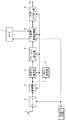
図1は本発明の実施の形態1におけるデジタル放送受信装置のブロック構成図を示す。図1において、チューナ1、復調器2、主信号復号器3、TMCC復号器4、ダミースロット挿入器5、TS選択速度変換器6、メモリ7は、図13のチューナ1001、復調器1002、主信号復号器1003、TMCC復号器1004、ダミースロット挿入器1005、TS選択速度変換器1006、メモリ1007と同様である。PCR付け替え器8はPCRの付け替えを行う。TS選択速度変換器6に関しては従来のデジタル放送受信装置と同様にTSの選択と速度変換を行うが、読み出しクロックの生成方法が異なっている。(Embodiment 1)
FIG. 1 is a block diagram of a digital broadcast receiving apparatus according to
図2は本発明のTS選択速度変換器6の詳細図である。図2におけるWE61、書き込みクロック62、書き込みアドレスカウンタ63、RE64、読み出しクロック65、読み出しアドレスカウンタ66、スロット数算出器68は、図16のWE1061、書き込みクロック1062、書き込みアドレスカウンタ1063、RE1064、読み出しクロック1065、読み出しアドレスカウンタ1066、スロット数算出器1068と同様である。変調モード分周比算出器69は変調方式および符号化率に応じて読み出しクロックの分周比を算出する。そして、分周回路67は、変調モード分周比算出器69が算出したクロックの分周比に基づいてクロックを分周・生成する。
FIG. 2 is a detailed view of the TS
以上のように構成されたデジタル放送受信装置について、以下、図を参照しながら動作を説明する。アンテナから信号を受信し、復調、復号処理を経て、ダミースロットを挿入して後段に出力するまでは従来のデジタル放送受信装置と同様の動作であるので、説明は省略する。 The operation of the digital broadcast receiving apparatus configured as described above will be described below with reference to the drawings. Since the operation from receiving a signal from an antenna, demodulating and decoding, inserting a dummy slot and outputting the signal to the subsequent stage is the same as that of a conventional digital broadcast receiving apparatus, description thereof is omitted.
ダミースロットを挿入されたTSはTS選択速度変換器6に入力される。まずは、TSの選択動作について、従来のデジタル放送受信装置との差異を説明する。本発明のデジタル放送受信装置では、TSを選択・出力する際にダミースロットを出力しないことを特徴とする。図15Cのフレームにおける「CH2」を選択したい場合、従来のデジタル放送受信装置では、スロット番号「45」からスロット番号「48」までの期間にWE1061信号を有効にして、メモリ1007に書き込む。本発明のデジタル放送受信装置では、有効スロットであるスロット番号「45」およびスロット番号「47」の期間のみWE61信号を有効にしてメモリ7に書き込む。このようなWE61信号の制御を行うことで、ダミースロット出力しないTSの選択が可能である。
The TS into which the dummy slot is inserted is input to the TS
次に、速度変換動作について説明する。従来のデジタル放送受信装置では、選択スロット数のみに応じて分周比を決定する。一方、本発明のデジタル放送受信装置では、変調方式および符号化率によっても分周比を決定する。前述のように、デジタル放送では変調方式および符号化率に応じてダミースロットの挿入量が決定される。本発明の速度変換ではダミースロットを考慮せずに速度変換をするので、「分周比=有効スロット数/(有効スロット数+無効スロット数)」となる。さらに、従来同様に選択スロットによる分周も行うため、最終的には「分周比=N/Nmax×有効スロット数/(有効スロット数+無効スロット数)」となる。 Next, the speed conversion operation will be described. In the conventional digital broadcast receiving apparatus, the frequency division ratio is determined only according to the number of selected slots. On the other hand, in the digital broadcast receiving apparatus of the present invention, the frequency division ratio is also determined by the modulation method and coding rate. As described above, in digital broadcasting, the amount of dummy slot insertion is determined according to the modulation method and coding rate. In the speed conversion according to the present invention, the speed conversion is performed without considering the dummy slot, so that “frequency division ratio = number of effective slots / (number of effective slots + number of invalid slots)”. Further, since the frequency division by the selected slot is also performed as in the prior art, the final result is “frequency division ratio = N / Nmax × number of effective slots / (number of valid slots + number of invalid slots)”.
図3Aから図3Cは本発明のBSデジタル放送の変調モードとTS出力例を示す図である。図3Aから図3Cにおいて、四角の枠は夫々のスロットを表し、夫々の四角の枠の左に記載されている数値はスロット番号を表している。図3Aは「CH1」と「CH2」の全体を示し、図3Bは「CH1」に相当し、図3Cは「CH2」に相当する。図15Cの例において、「CH2」を選択する際は、N=4、Nmax=48、有効スロット数=2、無効スロット数=2であるので、「CH2」を選択する際の分周比は、「4/48×2/(2+2)」となる。 FIG. 3A to FIG. 3C are diagrams showing a modulation mode and a TS output example of BS digital broadcasting according to the present invention. In FIG. 3A to FIG. 3C, a square frame represents each slot, and a numerical value written to the left of each square frame represents a slot number. 3A shows the entirety of “CH1” and “CH2”, FIG. 3B corresponds to “CH1”, and FIG. 3C corresponds to “CH2”. In the example of FIG. 15C, when “CH2” is selected, N = 4, Nmax = 48, the number of valid slots = 2, and the number of invalid slots = 2, so the frequency division ratio when selecting “CH2” is , “4/48 × 2 / ( 2 + 2) ”.
このときの出力TSは図3Cのようになり、48スロットの期間に2スロット分のデータが出力される。そのため、出力レートは実効レートとなり、従来の半分のレートで出力することができる。しかしながら、送信装置ではダミースロットが挿入されて出力されることを想定して時間調整のPCRが付加されているため、単にダミースロットを除去しただけでは出力TSのPCRに矛盾が生じてしまう。 The output TS at this time is as shown in FIG. 3C, and data for two slots is output in a period of 48 slots. Therefore, the output rate is an effective rate and can be output at half the conventional rate. However, in the transmission apparatus, a time adjustment PCR is added on the assumption that a dummy slot is inserted and output. Therefore, simply removing the dummy slot causes a contradiction in the PCR of the output TS.
そこで、本発明ではダミースロットなしで選択・速度変換されたTSがPCR付け替え器8に入力されて、PCR付け替え器8はPCRの付け替えを行う。そこで、図4はMPEG2−TSのパケット構成を示す。図4において、括弧内に記載されている数値はバイト数を表している。
Therefore, in the present invention, the TS that has been selected and speed-converted without a dummy slot is input to the
図4は、MPEG2−TSのパケット構成を示す。PCRは、図4に示すMPEG2−TSのパケット構成のように、188バイトのMPEG2−TSパケットのOptional Fieldsに48ビットで割り当てられている。 FIG. 4 shows the packet structure of MPEG2-TS. As shown in the MPEG2-TS packet structure shown in FIG. 4, the PCR is assigned to Optional Fields of 188-byte MPEG2-TS packet with 48 bits.
また、図5はMPEG2−TSでの多重化の構造を示している。図5において、「x0000」は数値表現形式を規定している記号である。MPEG2−TSではPCRは図5のように多重化されており、一般に以下の手順で抽出される。まず、パケット番号が「0」のパケットが探され、解析されて、PMTのPIDが取得される。次に、PIDがPMTのPIDと一致するパケットが探され、解析が行われて、PCRのPIDが取得される。最後にPIDがPCRのPIDと一致するパケットが探され、PCRの値が取得される。このようにして抽出されたPCRの値を本発明では次のように付け替える。 FIG. 5 shows a multiplexing structure in MPEG2-TS. In FIG. 5, “x0000” is a symbol that defines a numerical expression format. In MPEG2-TS, PCR is multiplexed as shown in FIG. 5 and is generally extracted by the following procedure. First, a packet whose packet number is “0” is searched and analyzed, and the PID of the PMT is acquired. Next, a packet whose PID matches the PID of the PMT is searched and analyzed, and the PID of the PCR is obtained. Finally, a packet whose PID matches the PID of the PCR is searched for, and the PCR value is obtained. In the present invention, the PCR values thus extracted are replaced as follows.
あるPCRをPCRnとし、その次のPCRをPCRn+1とする。そうして、PCRn+1とPCRnとの間のデータ量をPCRn+1とPCRnの値の差分で割ると、時間当たりのデータ量に相当する値が得られる。PCR付け替え器8に入力されるTSはTS選択速度変換器6でダミースロットが除去されているため、PCRn+1とPCRnと間のデータ量は「有効スロット数/(有効スロット数+無効スロット数)」となっている。そこで、PCRn+1とPCRnの値の差分も「有効スロット数/(有効スロット数+無効スロット数)」となるようPCRn+1を算出して、付け替えられる。この作業により、ダミースロットを除去したTSにおいてもPCRの矛盾がなくなり、正常に映像・音声を再生することができる。
One PCR is designated as PCRn, and the next PCR is designated as
なお、実施の形態1ではBSデジタル放送のフレーム構成を例にとったが、異なるフレーム構成においても実施の形態1と同様の受信装置の構成および処理フローで同様の効果を得ることができることは明らかである。そこで、図6はフレーム構成の例を示す。例えば、図6に示すようなフレーム構成を例に挙げて、以下説明する。図6において、枠の左に縦方向に記載されている数値はスロット番号を表し、各スロットにおけるパケット601を横方向に並べて示している。図6は、簡単のため、1フレームを10スロットとし、スロット番号「1」からスロット番号「5」に「CH1」が、スロット番号「6」からスロット番号「10」に「CH2」が割り当てられている場合を示している。また、スロットはスロットの下位概念であるパケット601(ここでは1スロット28パケット)に分割されている。また、変調方式の伝送効率の差をスロット単位のダミー挿入で解消し、符号化率による伝送効率の差をパケット単位のダミー挿入で解消するようなフレーム構成となっている。変調方式に応じたスロット単位のダミー603の挿入や、符号化率に応じたパケット単位のダミー602の挿入が行われている。
In the first embodiment, the BS digital broadcast frame configuration is taken as an example, but it is clear that the same effect can be obtained with the same configuration and processing flow of the receiving apparatus as in the first embodiment even in a different frame configuration. It is. FIG. 6 shows an example of the frame configuration. For example, a frame configuration as shown in FIG. 6 will be described as an example. In FIG. 6, the numerical value written in the vertical direction on the left of the frame represents the slot number, and the
次に、図7Aから図7Cはパケット単位での速度変換のTS出力を示す。図7Aは送信側でのフレームを示す。図7Bは受信側で「CH2」を選択時に全ダミーを除去する場合を示し、図7Cは受信側で「CH2」を選択時にスロット単位にダミーを除去する場合を示している。図6のようなフレーム構成の場合、図7Aに示す出力と図7Bに示す出力とが考えられる。図7Bは、すべてのダミーデータを除去する出力の場合を示し。図7Cは、スロット単位のダミーデータのみを除去し、1スロット当たりのパケット数は固定にした出力の場合を示す。これはメモリ7に書き込む際のWE61信号期間にパケット単位のダミーデータを含まなければ図7BのTS選択となり、含めれば図7CのTS選択となる。このときの分周比に関しては、図7B、図7CいずれのTS出力においても「分周比=選択パケット数/1フレームの全パケット数」とすることで、速度変換可能である。具体的な分周比は図7Bの場合は全スロット数が28パケット×10スロットの280パケットであるのに対し、選択パケット数が14パケット×4スロットの56パケットであることから、「分周比=56/280」となる。図7Cの場合は、同様に、選択パケット数が28パケット×4であることから「分周比=112/280」となる。同様にPCRに関してもPCRn+1とPCRnの値の差分も「選択パケット数/1フレームの全パケット数」となるように付け替えればよい。
Next, FIGS. 7A to 7C show the TS output of rate conversion in units of packets. FIG. 7A shows a frame on the transmission side. FIG. 7B shows a case where all dummies are removed when “CH2” is selected on the receiving side, and FIG. 7C shows a case where dummies are removed per slot when “CH2” is selected on the receiving side. In the case of the frame configuration as shown in FIG. 6, the output shown in FIG. 7A and the output shown in FIG. 7B can be considered. FIG. 7B shows the case of output from which all dummy data is removed. FIG. 7C shows a case where only dummy data for each slot is removed and the number of packets per slot is fixed. This is the TS selection of FIG. 7B if the dummy data for each packet is not included in the WE61 signal period when writing to the
このように、図6のフレーム構成においても実施の形態1と同様の構成および処理手順にて同様の効果を得ることができる。 Thus, the same effect can be obtained with the same configuration and processing procedure as in the first embodiment also in the frame configuration of FIG.
(実施の形態2)
次に、本発明の実施の形態2について説明する。実施の形態2は、出力するTSのダミースロットの有無と、PCRの付け替えを行うか行わないかの切換えを任意に変更できるようにしたものである。図8は本発明の実施の形態2におけるデジタル放送受信装置のブロック図である。なお、図8において、上記実施の形態1の図1と同一部分には同一符号を付し、詳しい説明は省略する。(Embodiment 2)
Next, a second embodiment of the present invention will be described. In the second embodiment, the presence / absence of the dummy slot of the TS to be output and the switching of whether or not to replace the PCR can be arbitrarily changed. FIG. 8 is a block diagram of a digital broadcast receiving apparatus according to
本発明のデジタル放送受信装置におけるTSの選択動作に関しては、ハードウェアの構成を変更することなく、WE61を有効にする期間にダミースロット期間を含めるかどうかを切り替えるだけで従来のデジタル放送受信装置の動作と切り替えることができる。同様に、速度変換動作に関しては「分周比=N/Nmax×有効スロット数/(有効スロット数+無効スロット数)」の分周比算出式において、「無効スロット数=0」とすることで、従来のデジタル放送受信装置と同様の速度変換処理に切り替えることができる。さらに、PCR付け替え処理に関しては、PCR付け替え値を決定する式「有効スロット数/(有効スロット数+無効スロット数)」において「無効スロット数=0」とすれば従来のデジタル放送受信装置と同様の動作に切り替えることができる。
With regard to the TS selection operation in the digital broadcast receiving apparatus of the present invention, the conventional digital broadcast receiving apparatus can be selected only by switching whether or not to include the dummy slot period in the period for enabling the
そうして、図8は本発明の実施の形態2におけるデジタル放送受信装置のブロック構成図を示す。図8において、実施の形態2におけるデジタル放送受信装置では、出力モード信号発生器9が設けられている。図8に示す実施の形態2におけるデジタル放送受信装置と、図1に示した実施の形態1におけるデジタル放送受信装置のブロック構成図との主な相違点は、この出力モード信号発生器9である。出力モード信号発生器9以外については、図1に示す実施の形態1におけるデジタル放送受信装置と同様であるため、出力モード信号発生器9を中心に説明する。出力モード信号発生器9は、TS選択速度変換器6およびPCR付け替え器8に出力モード信号を送る。送られた出力モード信号によって、例えば出力モード信号がHIであればTSの出力モードはダミースロットを挿入したTS出力のモードに切り替えられ、出力モード信号がLOWであればダミースロットを含まないTS出力のモードに切り替えられる。
FIG. 8 is a block diagram of the digital broadcast receiving apparatus according to
このような構成を取ることで、後段に出力するTSのモードを任意に切り替えることができるため、接続の互換性、柔軟性に優れた構成となる。 By adopting such a configuration, the mode of the TS to be output to the subsequent stage can be arbitrarily switched, so that the configuration is excellent in connection compatibility and flexibility.
なお、図6のようなフレーム構成で、ダミースロットの出力モードを図7Bまたは図7Cのようにさらに切り替えることが可能である。 In the frame configuration as shown in FIG. 6, the output mode of the dummy slot can be further switched as shown in FIG. 7B or 7C.
(実施の形態3)
次に、本発明における実施の形態3について説明する。発明の実施の形態3は、上述の出力モードの切換えをTMCCに割り当てた信号に基づいて変更できるようにしたものである。図9は本発明の実施の形態3におけるデジタル放送受信装置のブロック図を示す。なお、図9において実施の形態2の図8と同一部分には同一符号を付して詳しい説明は省略する。図9における、図8との差異は出力モード信号発生器9にTMCC復号装置4で復号されたTMCC信号が入力されている点である。以下、この点を中心に説明する。(Embodiment 3)
Next, a third embodiment of the present invention will be described. In the third embodiment of the present invention, the switching of the output mode described above can be changed based on a signal assigned to the TMCC. FIG. 9 shows a block diagram of a digital broadcast receiving apparatus according to
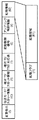
図10はBSデジタル放送のTMCC情報の構成を示す。図10において、括弧内に記載されている数値はバイト数を示している。例えば、TMCCの「拡張領域」の所定のビットに出力モードを表す信号が割り当てられている。デジタル放送受信装置は、このビットが0であれば従来のデジタル放送受信装置の出力モードで、1であれば本発明のデジタル放送受信装置の出力モードで出力する。このような構成を取ることで、本発明のデジタル放送受信装置は、TMCC信号に応じて自動的に出力モードを切り替えることができる。これにより、例えば伝送レートの低い放送は従来の出力モードで、高い放送は本発明の出力モードと言った具合に使い分けることが可能である。 FIG. 10 shows the structure of TMCC information of BS digital broadcasting. In FIG. 10, the numerical value described in parentheses indicates the number of bytes. For example, a signal indicating an output mode is assigned to a predetermined bit of the “extension area” of TMCC. If this bit is 0, the digital broadcast receiving apparatus outputs in the output mode of the conventional digital broadcast receiving apparatus. If the bit is 1, the digital broadcast receiving apparatus outputs in the output mode of the digital broadcast receiving apparatus of the present invention. By taking such a configuration, the digital broadcast receiving apparatus of the present invention can automatically switch the output mode according to the TMCC signal. Thus, for example, a broadcast with a low transmission rate can be used in a conventional output mode, and a broadcast with a high transmission rate can be properly used as an output mode of the present invention.
なお、図6のようなフレーム構成で、ダミースロットの出力モードを図7Bまたは図7Cのようにさらに切り替える場合には、TMCCにさらにもう1ビットを割り当てれば、出力モードを選択可能であることは明らかである。 When the output mode of the dummy slot is further switched as shown in FIG. 7B or 7C in the frame configuration as shown in FIG. 6, the output mode can be selected by assigning another bit to TMCC. Is clear.
(実施の形態4)
次に、本発明における実施の形態4について説明する。前述のように、デジタル放送では、伝送効率に応じてダミースロットを割り当てることとなっている。そのため従来の送信装置側では、受信装置側がダミースロットを挿入することを前提にダミースロットを考慮してPCRを設定し、送信装置側からはダミースロットのない状態で受信装置に送信する。本発明の受信装置側でダミースロットを付加せずに出力することを前提にしている。そこであらかじめ、受信装置側でダミースロットを除去することを想定して、送信装置側でPCRを付加する際にダミースロットを考慮せずPCRを付加する。(Embodiment 4)
Next, a fourth embodiment of the present invention will be described. As described above, in digital broadcasting, dummy slots are assigned according to transmission efficiency. Therefore, on the conventional transmitting apparatus side, the PCR is set in consideration of the dummy slot on the premise that the receiving apparatus side inserts the dummy slot, and the transmitting apparatus side transmits to the receiving apparatus without the dummy slot. It is assumed that the receiving apparatus of the present invention outputs without adding a dummy slot. Therefore, assuming that the receiving apparatus side removes the dummy slot in advance, the PCR is added without considering the dummy slot when adding the PCR on the transmitting apparatus side.
このように送信装置側でPCR設定されたTS信号を受信するデジタル放送受信装置の構成は、従来の図13におけるデジタル放送受信装置のTS選択速度変換器1006が図2の構成になったものである。この構成において、実施の形態1と同様のTS選択処理および速度変換処理を行うことで、実効レートでTSを出力することができる。
In this way, the configuration of the digital broadcast receiving device that receives the TS signal set by PCR on the transmitting device side is the one in which the conventional TS
(実施の形態5)
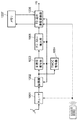
次に、本発明における実施の形態5について説明する。図11は、本発明の実施の形態5における多重化装置の構成例を示す図である。発明の実施の形態5における多重化装置は、ダミースロット付加器10、PCR打ち直し器11、PCRモード切り替えスイッチ12、ダミースロット除去器13、TS多重器14、変調器15を備えている。(Embodiment 5)
Next, a fifth embodiment of the present invention will be described. FIG. 11 is a diagram illustrating a configuration example of the multiplexing device according to the fifth embodiment of the present invention. The multiplexing apparatus according to the fifth embodiment of the present invention includes a
実施の形態5での送信側の多重化処理において、実施の形態4と異なっている点は、ダミースロットを考慮してPCRを付加するモードとダミースロットを考慮せずにPCRを付加するモードとを選択的に切り替えることができる点である。以下、この点を中心に説明する。 The multiplexing process on the transmission side in the fifth embodiment differs from the fourth embodiment in that a mode in which PCR is added in consideration of dummy slots and a mode in which PCR is added without consideration of dummy slots. It is a point which can be switched selectively. Hereinafter, this point will be mainly described.
あらかじめ、PCRを付加されたTSはダミースロット付加器10に入力され、変調方式と符号化率に応じてダミースロットが付加される。PCR打ち直し器11は、ダミースロットが付加されたTSに対してダミースロットを考慮してPCRを付加しなおしたTSを生成する。ダミースロット付加器10から出力されるPCRを打ち直さないTSとPCR打ち直し器11から出力されるダミースロットが付加されたTSの2系統がPCRモード切り替えスイッチ12に入力される。PCRモード切り替えスイッチ12は、PCRモード選択信号によってダミースロットを考慮してPCRを打ち直したTSか、ダミースロットを考慮せずにPCRを付加したTSの選択を行う。選択されたTSのみが、ダミースロット除去器13を介して、TS多重器14に供給される。TS多重器14は複数のTSやTMCC情報などを多重し、変調器15に供給する。変調器15は供給された情報を変調し、変調波として出力する。なお、PCRモード切り替えスイッチ12は、ダミースロットを挿入する出力モードと実効レートでの出力モードとを切り替える出力モード切り替え器の一例である。
The TS to which PCR is added in advance is input to the
このような構成とすることで、PCRの付加方法を番組や変調方式に応じて任意に選択することが可能となる。 With such a configuration, it is possible to arbitrarily select a PCR addition method according to a program or a modulation method.
(実施の形態6)
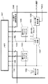
次に、本発明における実施の形態6について説明する。図12は、本発明の実施の形態6の多重化装置の構成例を示す図である。図12に示した本実施の形態の多重化装置の構成例が図11に示した実施の形態5の多重化装置の構成例と異なる点は、PCRモード選択信号がTS多重器14にも入力されている点である。以下、この点を中心に説明する。(Embodiment 6)
Next, a sixth embodiment of the present invention will be described. FIG. 12 is a diagram illustrating a configuration example of the multiplexing device according to the sixth embodiment of the present invention. The configuration example of the multiplexing device of the present embodiment shown in FIG. 12 is different from the configuration example of the multiplexing device of the fifth embodiment shown in FIG. 11 in that the PCR mode selection signal is also input to the
PCRモード選択信号はPCRモード切り替えスイッチ12に入力され、PCRモード切り替えスイッチ12はダミースロットを考慮してPCRを打ち直したTSか、ダミースロットを考慮せずにPCRを付加したTSの選択を行う。それととともに、PCRモード選択信号はTS多重器14にも入力される。TS多重器14は、PCRモード選択信号をTMCCの拡張領域に割り付けてTSに多重化する。
The PCR mode selection signal is input to the PCR
受信装置側は、このようにしてTMCCの拡張領域に割り当てられたPCRモード選択信号の情報を利用することで、送信側でのPCR付加のモードがダミースロットを考慮したモードか、考慮していないモードかを判別することができる。そこで、送信側がダミースロットを考慮してPCRを付加していれば、受信装置側でもダミースロットを付加して出力し、送信側がダミースロットを考慮せずにPCRを付加していれば、受信装置側でもダミースロットを付加しないといった処理を自動で行うことができる。なお、受信装置側でのダミースロットの付加や除去の処理は、実施の形態2と同様であるため、説明は省略する。
By using the information of the PCR mode selection signal assigned to the TMCC extension area in this way, the receiving device side does not consider whether the mode of PCR addition on the transmitting side is a mode that considers dummy slots or not. The mode can be determined. Therefore, if the transmitting side adds a PCR in consideration of a dummy slot, the receiving apparatus also adds a dummy slot and outputs it. If the transmitting side adds a PCR without considering a dummy slot, the receiving apparatus On the side, processing such as adding no dummy slot can be performed automatically. Note that the processing for adding and removing dummy slots on the receiving device side is the same as that in
なお、本発明の実施例ではBSデジタル放送を例に取ったが、本発明はBSデジタル放送に限定されるものではなく、地上波デジタル放送、CATVデジタル放送などの様々なデジタル放送にて実施可能である。 In the embodiment of the present invention, BS digital broadcasting is taken as an example, but the present invention is not limited to BS digital broadcasting, and can be implemented in various digital broadcasting such as terrestrial digital broadcasting and CATV digital broadcasting. It is.
以上の説明から明らかな通り、本発明のデジタル放送受信装置は、ダミースロットを含まずにTSを出力するTS選択機能と、変調方式と符号化率と選択スロット数に応じて分周した読み出しクロックで速度変換を行う速度変換機能と、変調方式と符号化率に応じてPCRを付け替えるPCR付け替え機能を備えることにより、TSの出力レートを実効レートに抑えてTSを出力できる。 As is apparent from the above description, the digital broadcast receiving apparatus of the present invention includes a TS selection function for outputting a TS without including a dummy slot, a read clock divided according to the modulation scheme, coding rate, and number of selected slots. By providing a speed conversion function for performing speed conversion and a PCR replacement function for replacing the PCR according to the modulation method and coding rate, the TS output rate can be suppressed to the effective rate and the TS can be output.
本発明にかかるデジタル放送受信装置は、ダミースロットの有無に応じたPCR管理を行うTS多重化装置によって多重化されたTS信号を、出力レートを実効レートに抑えて出力することができるものであり、伝送量の大きな信号を扱うデジタル放送受信装置等において有用である。 The digital broadcast receiving apparatus according to the present invention is capable of outputting a TS signal multiplexed by a TS multiplexing apparatus that performs PCR management according to the presence or absence of a dummy slot while suppressing the output rate to an effective rate. It is useful in a digital broadcast receiving apparatus that handles signals with a large transmission amount.
1 チューナ
2 復調器
3 主信号復号器
4 TMCC復号器
5 ダミースロット挿入器
6 TS選択速度変換器
7 メモリ
8 PCR付け替え器
9 出力モード信号発生器
10 ダミースロット付加器
11 PCR打ち直し器
12 PCRモード切り替えスイッチ
13 ダミースロット除去器
14 TS多重器
15 変調器DESCRIPTION OF
Claims (1)
1以上のチャンネルで構成され、前記チャンネルは変調方式と前記変調方式の符号化率との組み合わせに割り当てられた有効スロット及び無効スロットから構成されるTS信号から、選局されたチャンネルに含まれる有効スロットを前記メモリに所定のクロックで書き込み、前記メモリに書き込んだ前記選局されたチャンネルに含まれる有効スロットを、前記選局されたチャンネルの全てのスロットにおける有効スロットの割合で前記所定のクロックを分周したクロックで読み出し出力するTS選択速度変換器と、
前記選局されたチャンネルに含まれるPCRの値を、前記選局されたチャンネルの全てのスロットにおける有効ストッロの割合となるように算出して、前記選局されたチャンネルに含まれるPCRの値を前記算出したPCRの値に付け替えるPCR付け替え器と、
を備えるデジタル放送受信装置。Memory,
The channel is composed of one or more channels, and the channel is included in the channel selected from the TS signal composed of the effective slot and the invalid slot allocated to the combination of the modulation scheme and the coding rate of the modulation scheme. The slot is written to the memory with a predetermined clock, and the effective slot included in the selected channel written to the memory is changed to the effective clock included in all the slots of the selected channel. TS selection speed converter that reads out and outputs with the divided clock,
The PCR value included in the selected channel is calculated so as to be the ratio of effective slots in all slots of the selected channel, and the PCR value included in the selected channel is calculated. A PCR changer for changing the calculated PCR value ;
A digital broadcast receiving apparatus.
Priority Applications (1)
| Application Number | Priority Date | Filing Date | Title |
|---|---|---|---|
| JP2010509070A JP5146530B2 (en) | 2008-04-21 | 2009-04-20 | Digital broadcast transmitter / receiver |
Applications Claiming Priority (4)
| Application Number | Priority Date | Filing Date | Title |
|---|---|---|---|
| JP2008109797 | 2008-04-21 | ||
| JP2008109797 | 2008-04-21 | ||
| PCT/JP2009/001789 WO2009130875A1 (en) | 2008-04-21 | 2009-04-20 | Digital broadcast transmission/reception device |
| JP2010509070A JP5146530B2 (en) | 2008-04-21 | 2009-04-20 | Digital broadcast transmitter / receiver |
Publications (2)
| Publication Number | Publication Date |
|---|---|
| JPWO2009130875A1 JPWO2009130875A1 (en) | 2011-08-11 |
| JP5146530B2 true JP5146530B2 (en) | 2013-02-20 |
Family
ID=41216617
Family Applications (1)
| Application Number | Title | Priority Date | Filing Date |
|---|---|---|---|
| JP2010509070A Expired - Fee Related JP5146530B2 (en) | 2008-04-21 | 2009-04-20 | Digital broadcast transmitter / receiver |
Country Status (2)
| Country | Link |
|---|---|
| JP (1) | JP5146530B2 (en) |
| WO (1) | WO2009130875A1 (en) |
Families Citing this family (2)
| Publication number | Priority date | Publication date | Assignee | Title |
|---|---|---|---|---|
| WO2015075880A1 (en) * | 2013-11-22 | 2015-05-28 | パナソニック インテレクチュアル プロパティ コーポレーション オブ アメリカ | Transmission method, receiving method, transmission device and receiving device |
| JP6506009B2 (en) * | 2013-11-22 | 2019-04-24 | パナソニック インテレクチュアル プロパティ コーポレーション オブ アメリカPanasonic Intellectual Property Corporation of America | Transmission method, reception method, transmission apparatus, and reception apparatus |
Citations (4)
| Publication number | Priority date | Publication date | Assignee | Title |
|---|---|---|---|---|
| JPH10322388A (en) * | 1997-05-16 | 1998-12-04 | Nippon Hoso Kyokai <Nhk> | Digital signal transmission method and digital signal transmission system |
| JPH11205789A (en) * | 1998-01-16 | 1999-07-30 | Nec Corp | Transmission rate converter of mpeg2 transport stream |
| JP2002026853A (en) * | 2000-07-04 | 2002-01-25 | Sony Corp | Device and method for outputting transport stream |
| JP2004088758A (en) * | 2002-07-04 | 2004-03-18 | Matsushita Electric Ind Co Ltd | Apparatus and method for conversion of digital stream |
-
2009
- 2009-04-20 JP JP2010509070A patent/JP5146530B2/en not_active Expired - Fee Related
- 2009-04-20 WO PCT/JP2009/001789 patent/WO2009130875A1/en active Application Filing
Patent Citations (4)
| Publication number | Priority date | Publication date | Assignee | Title |
|---|---|---|---|---|
| JPH10322388A (en) * | 1997-05-16 | 1998-12-04 | Nippon Hoso Kyokai <Nhk> | Digital signal transmission method and digital signal transmission system |
| JPH11205789A (en) * | 1998-01-16 | 1999-07-30 | Nec Corp | Transmission rate converter of mpeg2 transport stream |
| JP2002026853A (en) * | 2000-07-04 | 2002-01-25 | Sony Corp | Device and method for outputting transport stream |
| JP2004088758A (en) * | 2002-07-04 | 2004-03-18 | Matsushita Electric Ind Co Ltd | Apparatus and method for conversion of digital stream |
Also Published As
| Publication number | Publication date |
|---|---|
| WO2009130875A1 (en) | 2009-10-29 |
| JPWO2009130875A1 (en) | 2011-08-11 |
Similar Documents
| Publication | Publication Date | Title |
|---|---|---|
| KR101138281B1 (en) | Format method of transport stream packet for improve receiving performance and digital broadcasting transmission and reception apparatus and method thereof | |
| RU2461128C2 (en) | Receiving device and receiving method, program and receiving system | |
| JP2007104085A (en) | Digital broadcast method and apparatus employing communication line | |
| JP2009525657A (en) | Transport stream jitter removal | |
| CN109873692B (en) | Reception method and reception LSI | |
| JP4339322B2 (en) | Transport stream receiving apparatus for providing multiple screens and control method thereof | |
| JP5145261B2 (en) | Digital data transmitter and digital data receiver | |
| JP5146530B2 (en) | Digital broadcast transmitter / receiver | |
| WO2011001863A1 (en) | Data processing device, data processing method, and program | |
| JP5970957B2 (en) | TRANSMISSION DEVICE, TRANSMISSION METHOD, RECEPTION DEVICE, RECEPTION METHOD, PROGRAM, AND ELECTRONIC DEVICE | |
| JP5476997B2 (en) | Receiving apparatus and method, program, and receiving system | |
| JP2012060481A (en) | Receiver, reception method and program | |
| JP4475273B2 (en) | Information processing apparatus and method | |
| JP4374107B2 (en) | TS multiplexing transmitter, receiver and transmission system | |
| JP2001078158A (en) | Transmitting device, multiplexing device and receiving device for cable television | |
| JP2009278186A (en) | Rate converter | |
| JP7046809B2 (en) | Receiver and receiving method | |
| JP2002185901A (en) | Digital broadcast receiver | |
| JP4099743B2 (en) | Recording apparatus and method, and recording medium | |
| JP4786619B2 (en) | Recording device | |
| JP3885068B2 (en) | Digital data receiving apparatus, digital data receiving method, and computer program | |
| JPH11340936A (en) | Method and device for multiplexing data | |
| JP2005354732A (en) | Transmission apparatus for cable television, multiplexer and reception apparatus | |
| US10178040B2 (en) | Data processing device, receiving device, data processing method, and program | |
| JP6063281B2 (en) | Transmission device, reception device, and programs thereof |
Legal Events
| Date | Code | Title | Description |
|---|---|---|---|
| A521 | Request for written amendment filed |
Free format text: JAPANESE INTERMEDIATE CODE: A523 Effective date: 20101015 |
|
| A621 | Written request for application examination |
Free format text: JAPANESE INTERMEDIATE CODE: A621 Effective date: 20111226 |
|
| A621 | Written request for application examination |
Free format text: JAPANESE INTERMEDIATE CODE: A621 Effective date: 20111226 |
|
| A131 | Notification of reasons for refusal |
Free format text: JAPANESE INTERMEDIATE CODE: A131 Effective date: 20120619 |
|
| A521 | Request for written amendment filed |
Free format text: JAPANESE INTERMEDIATE CODE: A523 Effective date: 20120806 |
|
| A131 | Notification of reasons for refusal |
Free format text: JAPANESE INTERMEDIATE CODE: A131 Effective date: 20120911 |
|
| A521 | Request for written amendment filed |
Free format text: JAPANESE INTERMEDIATE CODE: A523 Effective date: 20121004 |
|
| TRDD | Decision of grant or rejection written | ||
| A01 | Written decision to grant a patent or to grant a registration (utility model) |
Free format text: JAPANESE INTERMEDIATE CODE: A01 Effective date: 20121030 |
|
| A61 | First payment of annual fees (during grant procedure) |
Free format text: JAPANESE INTERMEDIATE CODE: A61 Effective date: 20121112 |
|
| R151 | Written notification of patent or utility model registration |
Ref document number: 5146530 Country of ref document: JP Free format text: JAPANESE INTERMEDIATE CODE: R151 |
|
| FPAY | Renewal fee payment (event date is renewal date of database) |
Free format text: PAYMENT UNTIL: 20151207 Year of fee payment: 3 |
|
| LAPS | Cancellation because of no payment of annual fees |