JP5144792B2 - Lamp - Google Patents
Lamp Download PDFInfo
- Publication number
- JP5144792B2 JP5144792B2 JP2011148856A JP2011148856A JP5144792B2 JP 5144792 B2 JP5144792 B2 JP 5144792B2 JP 2011148856 A JP2011148856 A JP 2011148856A JP 2011148856 A JP2011148856 A JP 2011148856A JP 5144792 B2 JP5144792 B2 JP 5144792B2
- Authority
- JP
- Japan
- Prior art keywords
- housing
- radiator
- lamp
- air guide
- guide wall
- Prior art date
- Legal status (The legal status is an assumption and is not a legal conclusion. Google has not performed a legal analysis and makes no representation as to the accuracy of the status listed.)
- Expired - Fee Related
Links
- 230000004888 barrier function Effects 0.000 claims description 28
- 230000000903 blocking effect Effects 0.000 claims description 19
- 239000000758 substrate Substances 0.000 claims description 19
- 230000002093 peripheral effect Effects 0.000 claims description 12
- 230000000694 effects Effects 0.000 description 14
- 230000017525 heat dissipation Effects 0.000 description 13
- 238000004519 manufacturing process Methods 0.000 description 6
- 238000012545 processing Methods 0.000 description 6
- 238000013461 design Methods 0.000 description 4
- 230000001965 increasing effect Effects 0.000 description 4
- 230000002411 adverse Effects 0.000 description 3
- 230000008901 benefit Effects 0.000 description 3
- 238000009423 ventilation Methods 0.000 description 3
- 238000013459 approach Methods 0.000 description 1
- 239000004568 cement Substances 0.000 description 1
- 239000003086 colorant Substances 0.000 description 1
- 239000004020 conductor Substances 0.000 description 1
- 230000008878 coupling Effects 0.000 description 1
- 238000010168 coupling process Methods 0.000 description 1
- 238000005859 coupling reaction Methods 0.000 description 1
- 238000005034 decoration Methods 0.000 description 1
- 238000007599 discharging Methods 0.000 description 1
- 230000005611 electricity Effects 0.000 description 1
- 230000002708 enhancing effect Effects 0.000 description 1
- 230000001815 facial effect Effects 0.000 description 1
- 230000001795 light effect Effects 0.000 description 1
- 238000012423 maintenance Methods 0.000 description 1
- 238000000034 method Methods 0.000 description 1
- 230000008569 process Effects 0.000 description 1
- 230000005855 radiation Effects 0.000 description 1
Images
Classifications
-
- F—MECHANICAL ENGINEERING; LIGHTING; HEATING; WEAPONS; BLASTING
- F21—LIGHTING
- F21V—FUNCTIONAL FEATURES OR DETAILS OF LIGHTING DEVICES OR SYSTEMS THEREOF; STRUCTURAL COMBINATIONS OF LIGHTING DEVICES WITH OTHER ARTICLES, NOT OTHERWISE PROVIDED FOR
- F21V29/00—Protecting lighting devices from thermal damage; Cooling or heating arrangements specially adapted for lighting devices or systems
-
- F—MECHANICAL ENGINEERING; LIGHTING; HEATING; WEAPONS; BLASTING
- F21—LIGHTING
- F21V—FUNCTIONAL FEATURES OR DETAILS OF LIGHTING DEVICES OR SYSTEMS THEREOF; STRUCTURAL COMBINATIONS OF LIGHTING DEVICES WITH OTHER ARTICLES, NOT OTHERWISE PROVIDED FOR
- F21V3/00—Globes; Bowls; Cover glasses
-
- F—MECHANICAL ENGINEERING; LIGHTING; HEATING; WEAPONS; BLASTING
- F21—LIGHTING
- F21K—NON-ELECTRIC LIGHT SOURCES USING LUMINESCENCE; LIGHT SOURCES USING ELECTROCHEMILUMINESCENCE; LIGHT SOURCES USING CHARGES OF COMBUSTIBLE MATERIAL; LIGHT SOURCES USING SEMICONDUCTOR DEVICES AS LIGHT-GENERATING ELEMENTS; LIGHT SOURCES NOT OTHERWISE PROVIDED FOR
- F21K9/00—Light sources using semiconductor devices as light-generating elements, e.g. using light-emitting diodes [LED] or lasers
- F21K9/20—Light sources comprising attachment means
- F21K9/23—Retrofit light sources for lighting devices with a single fitting for each light source, e.g. for substitution of incandescent lamps with bayonet or threaded fittings
- F21K9/232—Retrofit light sources for lighting devices with a single fitting for each light source, e.g. for substitution of incandescent lamps with bayonet or threaded fittings specially adapted for generating an essentially omnidirectional light distribution, e.g. with a glass bulb
-
- F—MECHANICAL ENGINEERING; LIGHTING; HEATING; WEAPONS; BLASTING
- F21—LIGHTING
- F21V—FUNCTIONAL FEATURES OR DETAILS OF LIGHTING DEVICES OR SYSTEMS THEREOF; STRUCTURAL COMBINATIONS OF LIGHTING DEVICES WITH OTHER ARTICLES, NOT OTHERWISE PROVIDED FOR
- F21V17/00—Fastening of component parts of lighting devices, e.g. shades, globes, refractors, reflectors, filters, screens, grids or protective cages
-
- F—MECHANICAL ENGINEERING; LIGHTING; HEATING; WEAPONS; BLASTING
- F21—LIGHTING
- F21V—FUNCTIONAL FEATURES OR DETAILS OF LIGHTING DEVICES OR SYSTEMS THEREOF; STRUCTURAL COMBINATIONS OF LIGHTING DEVICES WITH OTHER ARTICLES, NOT OTHERWISE PROVIDED FOR
- F21V29/00—Protecting lighting devices from thermal damage; Cooling or heating arrangements specially adapted for lighting devices or systems
- F21V29/50—Cooling arrangements
- F21V29/60—Cooling arrangements characterised by the use of a forced flow of gas, e.g. air
- F21V29/67—Cooling arrangements characterised by the use of a forced flow of gas, e.g. air characterised by the arrangement of fans
- F21V29/673—Cooling arrangements characterised by the use of a forced flow of gas, e.g. air characterised by the arrangement of fans the fans being used for intake
-
- F—MECHANICAL ENGINEERING; LIGHTING; HEATING; WEAPONS; BLASTING
- F21—LIGHTING
- F21V—FUNCTIONAL FEATURES OR DETAILS OF LIGHTING DEVICES OR SYSTEMS THEREOF; STRUCTURAL COMBINATIONS OF LIGHTING DEVICES WITH OTHER ARTICLES, NOT OTHERWISE PROVIDED FOR
- F21V29/00—Protecting lighting devices from thermal damage; Cooling or heating arrangements specially adapted for lighting devices or systems
- F21V29/50—Cooling arrangements
- F21V29/60—Cooling arrangements characterised by the use of a forced flow of gas, e.g. air
- F21V29/67—Cooling arrangements characterised by the use of a forced flow of gas, e.g. air characterised by the arrangement of fans
- F21V29/677—Cooling arrangements characterised by the use of a forced flow of gas, e.g. air characterised by the arrangement of fans the fans being used for discharging
-
- F—MECHANICAL ENGINEERING; LIGHTING; HEATING; WEAPONS; BLASTING
- F21—LIGHTING
- F21V—FUNCTIONAL FEATURES OR DETAILS OF LIGHTING DEVICES OR SYSTEMS THEREOF; STRUCTURAL COMBINATIONS OF LIGHTING DEVICES WITH OTHER ARTICLES, NOT OTHERWISE PROVIDED FOR
- F21V29/00—Protecting lighting devices from thermal damage; Cooling or heating arrangements specially adapted for lighting devices or systems
- F21V29/50—Cooling arrangements
- F21V29/70—Cooling arrangements characterised by passive heat-dissipating elements, e.g. heat-sinks
- F21V29/83—Cooling arrangements characterised by passive heat-dissipating elements, e.g. heat-sinks the elements having apertures, ducts or channels, e.g. heat radiation holes
-
- F—MECHANICAL ENGINEERING; LIGHTING; HEATING; WEAPONS; BLASTING
- F21—LIGHTING
- F21V—FUNCTIONAL FEATURES OR DETAILS OF LIGHTING DEVICES OR SYSTEMS THEREOF; STRUCTURAL COMBINATIONS OF LIGHTING DEVICES WITH OTHER ARTICLES, NOT OTHERWISE PROVIDED FOR
- F21V29/00—Protecting lighting devices from thermal damage; Cooling or heating arrangements specially adapted for lighting devices or systems
- F21V29/50—Cooling arrangements
- F21V29/70—Cooling arrangements characterised by passive heat-dissipating elements, e.g. heat-sinks
- F21V29/74—Cooling arrangements characterised by passive heat-dissipating elements, e.g. heat-sinks with fins or blades
- F21V29/76—Cooling arrangements characterised by passive heat-dissipating elements, e.g. heat-sinks with fins or blades with essentially identical parallel planar fins or blades, e.g. with comb-like cross-section
- F21V29/763—Cooling arrangements characterised by passive heat-dissipating elements, e.g. heat-sinks with fins or blades with essentially identical parallel planar fins or blades, e.g. with comb-like cross-section the planes containing the fins or blades having the direction of the light emitting axis
-
- F—MECHANICAL ENGINEERING; LIGHTING; HEATING; WEAPONS; BLASTING
- F21—LIGHTING
- F21Y—INDEXING SCHEME ASSOCIATED WITH SUBCLASSES F21K, F21L, F21S and F21V, RELATING TO THE FORM OR THE KIND OF THE LIGHT SOURCES OR OF THE COLOUR OF THE LIGHT EMITTED
- F21Y2105/00—Planar light sources
- F21Y2105/10—Planar light sources comprising a two-dimensional array of point-like light-generating elements
-
- F—MECHANICAL ENGINEERING; LIGHTING; HEATING; WEAPONS; BLASTING
- F21—LIGHTING
- F21Y—INDEXING SCHEME ASSOCIATED WITH SUBCLASSES F21K, F21L, F21S and F21V, RELATING TO THE FORM OR THE KIND OF THE LIGHT SOURCES OR OF THE COLOUR OF THE LIGHT EMITTED
- F21Y2115/00—Light-generating elements of semiconductor light sources
- F21Y2115/10—Light-emitting diodes [LED]
Landscapes
- Engineering & Computer Science (AREA)
- General Engineering & Computer Science (AREA)
- Physics & Mathematics (AREA)
- Microelectronics & Electronic Packaging (AREA)
- Optics & Photonics (AREA)
- Arrangement Of Elements, Cooling, Sealing, Or The Like Of Lighting Devices (AREA)
- Non-Portable Lighting Devices Or Systems Thereof (AREA)
- Cooling Or The Like Of Electrical Apparatus (AREA)
Description
本発明は、灯具に関するもので、特に放熱機能を有する灯具に係わるものである。 The present invention relates to a lamp, and particularly relates to a lamp having a heat dissipation function.
従来形態1の灯具として、図5に示す従来の中華民国公告第I316121号の「灯具」を参照すると、従来の灯具8には一個のハウジング81が含まれ、ハウジング81は一個の第一ハウジング体811と一個の第二ハウジング体812により構成される。その内に、第一ハウジング体811には一個の風排出部811aと一個の風進入部812aが設けられる。また、ハウジング81の内部には一個の放熱器82、一個の発光部材83と一個の放熱ファン84が設けられ、そして放熱器82は発光部材83と放熱ファン84の間に位置するように形成される。これにより、放熱ファン84が回転される時、外部の気流は風進入部812aを経由して吸入され、そして空気を導引して放熱器82を通過した後、再び風排出部811aから吹き出されることにより、発光部材83が作動時に生じられる熱エネルギーを低く抑えることができるようにしたものがある。
Referring to the “lamp” in the conventional public notice of the Republic of China No. I316121 shown in FIG. 5 as the lamp of the
また、従来形態2の灯具の構造としては、例えば図6に示される中華民国公告第M346745号の「端向排熱式LED灯具」を参照すると、従来の灯具には一個のハウジング91、一個の放熱器92、一個のファン93および一個のLED灯ユニット94が含まれる。ハウジング91は一個の上ハウジング911と一個の下ハウジング912により構成される。上ハウジング91には複数個の通気孔911aが設けられ、下ハウジング92には一個の貫穿孔921aが設けられる。放熱器92はハウジング91内に位置するとともに、下ハウジング912の貫穿孔912aとの間には通気路95を有するように形成される。ファン93もハウジング91の内に位置するとともに、放熱器92に結合される。LED灯ユニット94は放熱器92に結合される。これにより、ファン93が運転される時、外部の空気をそれぞれの通気孔911aを経由して吸入させた後、再び通気路95から貫穿孔912aを経て排出されることにより、LED灯ユニット94から生じる熱エネルギーを駆動して排出することができるようにとしたものがある。
Further, as the structure of the lamp of the
上記の図5に掲示されるような従来形態1の灯具においては、一般的に次のような問題点を有している。従来の灯具8を実際に供すると、灯具8のハウジング81は第一ハウジング体811と第二ハウジング体812によって組み合わせてなるものであるため、部材の数が増えてしまうばかりか、全体の構造が相対的に複雑になるとともに、放熱器82、発光部材83と放熱ファン84がハウジング81の内に被覆されるため、ハウジング81に他に複数個の孔からなる風排出部811aと風進入部812aを設けなければならず、そのために加工が不便になるとともに、製造コストが高くなるという問題点があった。
The lamp of the
また、装飾上における全体的な美観の需要性に応じて、従来の灯具8を装飾板の内部、例えば天井板などの場所に嵌入して内蔵させる場合、従来の灯具8の風排出部811aと風進入部812aがハウジング81に設けられるため、風排出部811aと風進入部812aも装飾板の内部、いわゆる天井板の上方に埋め込まれ、そして発光部材83だけが天井板の表面から露出することになる。しかし天井板の上方と建物そのもののセメントとの間の空間は一般的に密閉空間に形成されており、外部の空気との循環が難くなり、そして空気の流通が悪くなるため、放熱の効果に悪影響を及ぼし、さらに熱が溜まってしまうため、従来の灯具8の使用寿命に悪影響を及ぼしてしまうという問題点があった。
Further, when the
また、上記の図6に掲示されるような従来形態2の灯具においては、一般的に次のような問題点を有している。従来の灯具9のハウジング91は上ハウジング911と下ハウジング912により構成されるため、前述と同様に部材の数が増えてしまうばかりか、全体的構造が相対的に複雑になるという問題点があった。また、従来の灯具9の放熱器92と貫穿孔912aの間には通気路95を有するように形成されるが、依然として上ハウジング911に複数個の通気孔911aを設けなければならず、そのために従来の灯具9の構造においても同様に加工が不便になるとともに、製造コストが高くなるという問題点があった。さらに、従来の灯具9の構造においては、灯具9を天井板に嵌入して隠して設置しなければならない場合、通気路95は天井板の表面から露出しているが、それぞれの通気孔911aは依然として天井板の上方に埋め込まれるため、空気の流通と放熱の効果が悪くなり、さらに熱が溜まって灯具の使用寿命に悪影響を及ぼしてしまうという問題点があった。このように、上記のような従来の灯具の構造をさらに改良を必要とするものであった。
Further, the lamp of the
本発明はこのような問題点に鑑みて発明されたものであって、その主な目的とするところは、ハウジングにおいていかなる風進入孔または風排出孔を他に加工して設ける必要性をなくすことにより、構造の複雑性を有効に低く抑えるとともに、加工製造が便利になる灯具を提供することである。 The present invention has been invented in view of such problems, and its main object is to eliminate the need to provide any other wind inlet hole or wind outlet hole in the housing. Thus, it is possible to provide a lamp that effectively suppresses the complexity of the structure and is convenient for processing and manufacturing.
本発明の第二の目的は、灯具を嵌入内蔵式に取り付ける場合、外部の空気が灯具にスムースに進入することを確保することにより、全体の放熱の効果を高めるとともに、正常に作動するのを確保することができる灯具を提供することにある。 The second object of the present invention is to improve the overall heat dissipation effect and ensure normal operation by ensuring that external air smoothly enters the lamp when the lamp is mounted in a built-in manner. The object is to provide a lamp that can be secured.
上記目的を達成するために、本発明による灯具は、一個のハウジング、一個の放熱器、一個の放熱ファンおよび一個の発光モジュールを有する。ハウジングの一端には一個の組立口が設けられ、もう一方の一端には一個の電気の接続部材が設けられ、ハウジングが組立口に隣接する内側の周壁は一個の導風壁からなる。放熱器には一個の基板が含まれ、基板はハウジングの組立口に結合される。基板には少なくとも一個の阻隔板が設けられ、放熱器は少なくとも一個の阻隔板によって一個の気流通路が形成される。少なくとも一個の阻隔板とハウジングの導風壁の間には一個の第一導風口が形成され、気流通路とハウジングの導風壁の間には一個の第二導風口が形成される。放熱ファンは放熱器と結合し、放熱ファンには一個のファンホイールが含まれる。一個の発光モジュールは放熱器の基板に結合される。 In order to achieve the above object, a lamp according to the present invention has one housing, one heat radiator, one heat radiating fan, and one light emitting module. One end of the housing is provided with one assembly port, the other end is provided with one electrical connection member, and the inner peripheral wall of the housing adjacent to the assembly port is composed of one air guide wall. The radiator includes a single substrate, and the substrate is coupled to the assembly port of the housing. The substrate is provided with at least one blocking plate, and the radiator has one air flow path formed by at least one blocking plate. One first air inlet is formed between the at least one barrier plate and the air guide wall of the housing, and one second air inlet is formed between the air flow passage and the air guide wall of the housing. The heat dissipating fan is combined with the heat dissipator, and the heat dissipating fan includes one fan wheel. One light emitting module is coupled to the radiator substrate.
また、本発明による灯具は、基板の阻隔板は二個であり、二個の阻隔板間隔をもって相対するように気流通路が形成されることもできる。基板の阻隔板は一個であり、阻隔板は基板の外周縁を囲むように形成され、阻隔板にはハウジングの導風壁に向くように外側表面が形成され、外側表面と導風壁の間には第一導風口が形成され、さらに阻隔板には気流通路と連通する凹欠部が設けられ、凹欠部とハウジングの導風壁との間には第二導風口が形成されることもできる。また、放熱ファンには一個の係止片が設けられ、係止片は放熱器の凹欠部の位置に位置合わせるように形成されることもできる。また、放熱器の凹欠部の相対する両側の端縁にはそれぞれ一個の翼片が設けられ、二個の翼片はハウジングの導風壁に向いて延伸するように形成され、係止片は二個の翼片の間に位置するように形成されることもできる。また、放熱器の二個の翼片はハウジングの導風壁に当接するように形成されることもできる。また、他に一個の透光カバーが含まれ、透光カバーは放熱器と結合し、透光カバーには一個の開口部が含まれ、発光モジュールは開口部を通じて透光カバーの内部に収容されることもできる。また、透光カバーの外側の周壁には一個の導流肩部が設けられ、そしてハウジングの組立口に隣接する一端の端縁と導流肩部の間には一個の導流エアギャップが形成されることもできる。また、放熱器の気流通路には複数個のフィンが設けられ、それぞれのフィンの間には隙間が含まれることもできる。また、それぞれのフィンの相対する両端はそれぞれハウジングの導風壁に当接するように形成されることもできる。また、それぞれのフィンの相対する両端とハウジングの導風壁の間にはそれぞれ一個の隙間が形成されることもできる。また、それぞれのフィンの片側には一個の位置決め板が形成され、放熱ファンは放熱器の位置決め板に固定されることもできる。また、放熱器の少なくとも一個の阻隔板にはハウジングの導風壁に向くように第一端と第二端が含まれ、阻隔板の第一端と第二端はそれぞれハウジングの導風壁に当接するように形成されることもできる。また、ハウジングの内部には複数個の固定柱が設けられ、放熱器の外側の周縁には固定柱に対応するように複数個の取り付け部が形成され、放熱器は複数個の固定部材を利用して取り付け部と固定柱によって固定するように形成されることもできる。また、放熱ファンには一個のファンホイールが含まれ、ファンホイールは一個の回転範囲が含まれ、ファンホイールの半径方向において、放熱器の二個の阻隔板の間には一個の半径方向の距離が含まれ、ファンホイールは二個の阻隔板の間に位置するように形成され、そして半径方向の距離は回転範囲より大きくなるように、または同じになるように形成されることもできる。 In the lamp according to the present invention, the number of the barrier plates of the substrate is two, and the airflow passage can be formed so as to face each other with a distance between the two barrier plates. The board has a single barrier plate, and the barrier plate is formed so as to surround the outer peripheral edge of the substrate. The barrier plate is formed with an outer surface facing the air guide wall of the housing, and between the outer surface and the air guide wall. A first air inlet is formed on the wall, and a notch that communicates with the air flow passage is provided on the barrier plate, and a second air inlet is formed between the notch and the air guide wall of the housing. You can also. In addition, the heat dissipating fan may be provided with one locking piece, and the locking piece may be formed so as to be aligned with the position of the recessed portion of the radiator. In addition, one wing piece is provided at each of the opposite edges of the recessed portion of the radiator, and the two wing pieces are formed so as to extend toward the air guide wall of the housing. Can also be formed to be located between two wing pieces. Further, the two wing pieces of the radiator can be formed so as to contact the air guide wall of the housing. In addition, another transparent cover is included, the transparent cover is coupled to the radiator, the transparent cover includes one opening, and the light emitting module is accommodated in the transparent cover through the opening. You can also. In addition, one guide shoulder is provided on the outer peripheral wall of the translucent cover, and one guide air gap is formed between one end edge adjacent to the housing assembly opening and the guide shoulder. Can also be done. In addition, a plurality of fins may be provided in the airflow passage of the radiator, and a gap may be included between the fins. Moreover, the opposing both ends of each fin can also be formed so that it may contact | abut to the wind guide wall of a housing, respectively. In addition, a single gap may be formed between the opposing ends of each fin and the air guide wall of the housing. In addition, one positioning plate is formed on one side of each fin, and the heat radiating fan can be fixed to the positioning plate of the radiator. Further, at least one barrier plate of the radiator includes a first end and a second end so as to face the air guide wall of the housing, and the first end and the second end of the barrier plate are respectively connected to the air guide wall of the housing. It can also be formed to abut. In addition, a plurality of fixed pillars are provided inside the housing, and a plurality of mounting portions are formed on the outer periphery of the radiator to correspond to the fixed pillars. The radiator uses a plurality of fixing members. Then, it can be formed so as to be fixed by the mounting portion and the fixing column. In addition, the heat dissipation fan includes one fan wheel, the fan wheel includes one rotation range, and in the radial direction of the fan wheel, one radial distance is included between the two barrier plates of the radiator. The fan wheel may be formed so as to be positioned between the two barrier plates, and the radial distance may be formed to be greater than or equal to the rotation range.
本発明の灯具によれば、ハウジングにおいていかなる風進入孔または風排出孔も他に加工して設ける必要性がないため、構造の複雑性を有効に低く抑えるとともに、加工製造が便利になるという利点がある。 According to the lamp of the present invention, since it is not necessary to provide any other wind entrance hole or wind exhaust hole in the housing, it is possible to effectively reduce the complexity of the structure and to make the manufacturing process convenient. There is.
本発明の灯具によれば、灯具を嵌入内蔵式に取り付ける場合、外部の気流が灯具にスムーズに進入することを確保することにより、全体の放熱の効果を高めるとともに、正常に作動するのを確保することができるという利点がある。 According to the lamp of the present invention, when the lamp is installed in a built-in type, it is ensured that the external air flow smoothly enters the lamp, thereby enhancing the overall heat dissipation effect and ensuring normal operation. There is an advantage that you can.
本発明の実施の形態について、以下、図面を参照して説明する。 Embodiments of the present invention will be described below with reference to the drawings.
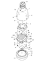
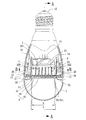
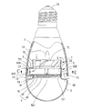
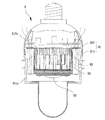
図1は本発明の実施例1の灯具の分解斜視図で、図2は本発明の実施例1の灯具の組み立てられた状態の断面図で、図3は図2のA−A線に沿った断面図である。図1〜3を参照すると、本発明の灯具には少なくとも一個のハウジング1、一個の放熱器2、一個の放熱ファン3および一個の発光モジュール4が含まれる。ハウジング1は放熱器2と放熱ファン3と発光モジュール4とが結合するのに用いられる。放熱器2はハウジング1の内部に設けられる。放熱ファン3は放熱器2と結合する。発光モジュール4は放熱器2と結合し、そして同様にハウジング1の内部に位置するように形成される。
1 is an exploded perspective view of a lamp according to a first embodiment of the present invention, FIG. 2 is a sectional view of the lamp according to the first embodiment of the present invention in an assembled state, and FIG. 3 is taken along line AA in FIG. FIG. 1-3, the lamp of the present invention includes at least one
ハウジング1は一個の中空のハウジング体からなり、ハウジング1の一端には一個の組立口11が設けられ、他端には一個の電気の接続部材12が設けられる。組立口11はハウジング1の内部と連通するように形成されることにより、放熱器2をハウジング1の内部にスムースに組み立てることができ、そしてハウジング1が組立口11に隣接する内側の周壁は一個の導風壁13からなる。電気の接続部材12は各種の外部の電源と電気的に連接することができる構造設計からなるため、本発明の灯具の主な電力源とすることができる。
The
図1aは本発明の実施例1の灯具の放熱器の外観斜視図である。図1aを参照すると、放熱器2は熱伝導性の材質によって製造され、放熱器2には一個の基板21が含まれる。基板21はハウジング1の組立口11に結合され、基板21には少なくとも一個の阻隔板22が設けられる。放熱器2は少なくとも一個の阻隔板22によって一個の気流通路221を形成する。本実施形態において、基板21には相互に離隔して対面するように二個の阻隔板22が設けられ、二個の阻隔板22の間には一個の気流通路221が形成される。
FIG. 1 a is an external perspective view of a radiator of the lamp according to the first embodiment of the present invention. Referring to FIG. 1 a, the
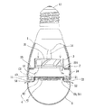
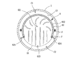
図4は図2のB−B線に沿った断面図である。図4を参照すると、二個の阻隔板22にはそれぞれハウジング1の導風壁13に向くように外側表面222が設けられる。二個の阻隔板22の外側表面222と導風壁13の間には一個の第一導風口C1が形成され、そして気流通路221とハウジング1の導風壁13の間には一個の第二導風口C2が形成される。その内、第一個の導風口C1と第二導風口C2は放熱ファン3の作動方向に従って風進入口または風排出口として選択することができ、例えば、第一導風口C1が風進入口として用いられる時、第二導風口C2を風排出口として用いることができ、また、第一導風口C1が風排出口として用いられる時、第二導風口C2を風進入口として用いることもできる。
FIG. 4 is a cross-sectional view taken along line BB in FIG. Referring to FIG. 4, the two
放熱ファン3は放熱器2と結合する。放熱ファン3は選択的に軸流式ファンまたは遠心式ファンからなることができ、好ましくは一個の軸流式ファンからなる。また、放熱ファン3には一個のファンホイール31が含まれ、そして放熱ファン3は例えばねじなどの固定部材Fを利用して放熱器2と固定することができるため、放熱器2によって予定される放熱効果を提供することができる。
The
発光モジュール4には一個の発光部材41と一個の制御基板42が含まれる。発光部材41は発光ダイオード(LED)、ランプまたはその他の発光機能を有する部材からなることができる。制御基板42は発光部材41と電気的に接続されるため、発光部材41が光を発するように制御することができる。本実施形態において、発光部材41は発光ダイオードからなるため、使用寿命と電気節約の効果を高めることができる。制御基板42はハウジング1の電気的接続部材12に電気的に接続され、そして制御基板42は放熱器2の基板21に貼接されることにより、放熱器2によって発光モジュール4が実際に作動時における温度を効果的に低く抑えることができるため、よりよい放熱効果を獲得することができる。
The
本発明の灯具を実際に使用する場合、例えば灯具を壁、天井板またはその他の照明を行おうとする場所に取り付けることができる。例を挙げてみると、灯具のハウジング1を装飾板の天井板の上方に埋め込み、そしてハウジング1の組立口11と発光モジュール4の発光部材41だけを天井板の表面から露出させる。他に、組立口11に隣接する導風壁13と放熱器2の間には第一導風口C1と第二導風口C2が形成されることにより、第一導風口C1と第二導風口C2も相対的に天井板の表面から露出するように形成される。さらに、ハウジング1の電気的接続部材12は一般的な電源を供給するシステムと電気的に連接することができ、そして電源を発光モジュール4の制御基板42まで提供することができるため、発光部材41が光を発するように制御することができる。また、図2を参照すると、放熱ファン3が運転されると、外部の空気を第一導風口C1を経由してハウジング1の内部と放熱器2の気流通路221まで導入させる。この時、図3を参照すると、更に進んで気流を第二導風口C2導出させることにより、発光モジュール4から生じられる熱エネルギーを補助的に駆動して排出することができる。
When the lamp of the present invention is actually used, for example, the lamp can be mounted on a wall, a ceiling plate, or other place where lighting is to be performed. As an example, the
上述した構造的特徴によると、本発明の実施例1の灯具の主要な利点は、本発明の灯具のハウジング1が直接組立口11と放熱器2の両者の間の構造空間を利用して第一導風口C1と第二導風口C2を形成させることができることにある。さらに詳しく言えば、放熱器2をハウジング1の組立口11に結合させる場合、二個の阻隔板22と導風壁13の間には第一導風口C1が形成され、そして気流通路221と導風壁13の間には第二導風口C2が形成される。そのため、本発明の灯具は直接組立の機能を有する組立口11を利用して第一導風口C1と第二導風口C2を形成させることにより、ハウジング1には他に加工を行っていかなる風進入孔または風排出孔を設ける必要がないため、全体の構造の複雑性を有効に低く抑えることができるとともに、加工の利便性を高めて製造コストを低く抑えることができる。また、仮に本発明の灯具を装飾板の天井板などの場所に嵌入して隠して設置する場合、第一導風口C1と第二導風口C2も対応するように天井板の表面に露出するように形成することができる。そのため、放熱ファン3によって空気をスムースに導入したり導出したりすることができるため、全体の放熱の機能を高めることができるとともに、本発明の灯具の使用寿命を有効に延ばすことができる。
According to the structural features described above, the main advantage of the lamp of the first embodiment of the present invention is that the
上述した本発明の実施例1の灯具の構造設計の概念に基づいて、本発明においても下記のように少なくとも一個の附属の構造特徴またはその組合せを含むことにより、本発明の灯具の機能はさらに完璧になる。 Based on the concept of the structural design of the lamp of the first embodiment of the present invention described above, the function of the lamp of the present invention is further improved by including at least one attached structural feature or a combination thereof as described below. Become perfect.
再び図1を参照すると、本発明の灯具には好ましくは他に一個の透光カバー5が含まれる。透光カバー5は放熱器2と結合し、そして透光カバー5には一個の開口部51が含まれ、発光モジュール4は開口部51を通じて透光カバー5の内部に収容される。その内、開口部51の外周面には外ねじ部511が設けられ、放熱器2は発光モジュール4の周辺において螺接部23が形成され、そして透光カバー5は外ねじ部511を利用して放熱器2の螺接部23に螺接して結合することができる。これにより、発光モジュール4は透光カバー5を通じて光を投射し、そして透光カバー5は使用上の需要性に応じて異なる顔色または種類の透光カバーを選択することにより、異なる光の効果を生じさせることができる。その他に、透光カバー5によって発光モジュール4を保護することを兼ねて用いることができる。全体的に言えば、上述した技術的特徴によれば、光を投射する効果と発光モジュール4を保護する効果を高めることができる。
Referring again to FIG. 1, the lamp of the present invention preferably further includes one
再び図1を参照すると、上述した透光カバー5の外側の周壁には一個の導流肩部52が設けられ、導流肩部52は開口51に隣接するように形成される。図2を参照すると、ハウジング1が組立口11に隣接する一端の端縁と導流肩部52の間には一個の導流エアギャップ53が形成され、それにより、放熱ファン3は導流エアギャップ53を経由して水平に気流を導引して第一導風口C1と第二導風口C2に進出することができ、そして導流肩部52を利用して気流をさらにスムースに導流エアギャップ53から進出させることができる。全体的に言えば、上述した技術的特徴によれば、空気の導流効果を高めることができる。
Referring again to FIG. 1, one
再び図1を参照すると、本発明の灯具の放熱器2の気流通路221には好ましくは複数個のフィン24が設けられ、それぞれのフィン24は互いの間には隙間を有するように形成され、そして二個の阻隔板22の間に位置するように形成される。これにより、放熱ファン3が気流を導引して気流通路221を通過する時、それぞれのフィン24によって放熱面積を増やすことができる。全体的に言えば、上述した技術的特徴によれば、放熱の効果を高めることができる。
Referring to FIG. 1 again, the
再び図4を参照すると、上述したそれぞれのフィン24の相対する両端はそれぞれハウジング1の導風壁13に当接するように形成される。これにより、放熱器2がハウジング1の組立口11に結合される時、放熱器2は確実にハウジング1の組立口11の内に貼接されるため、ハウジング1と放熱器2の結合の安定性を高めることができる。また、上述したそれぞれのフィン24の相対する両端とハウジング1の導風壁13の間もまたそれぞれ当接するように形成される一個の隙間が形成されることにより、放熱器2がハウジング1の組立口11の内に貼接されていなくても、それぞれのフィン24によって依然として第二導風口C2の風進入量または風排出量に惡影響を及ぼすのを防止することができるため、風の導入量を高めることができる。
Referring again to FIG. 4, the opposite ends of each
再び図1を参照すると、上述したそれぞれのフィン24が基板21から遠く離れる側には一個の位置決め板25が形成されることにより、放熱ファン3は例えばねじ等の固定部材Fを利用して放熱器2の位置決め板25と螺接することができ、そして放熱ファン3を固定するという機能を達することができるとともに、使用者によって放熱ファン3を随時にかつ簡単に放熱器2から取り外すことができるため、メンテナンスの上において大変便利になる。全体的に言えば、上述した技術的特徴によれば、取り外しの便利性を高めることができる。
Referring to FIG. 1 again, a
再び図4を参照すると、本発明の灯具の放熱器2の二個の阻隔板22にはそれぞれハウジング1の導風壁13に向くように形成された第一端223と第二端224が含まれ、阻隔板22の第一端223と第二端224はそれぞれハウジング1の導風壁13に当接するように形成されることにより、阻隔板22の設計を利用してさらに効果的に第一導風口C1と第二導風口C2を予め区画することができ、それにより、放熱ファン3が気流を導引して第一導風口C1と第二導風口C2に進入する過程において、阻隔板22によって乱流が生じるのを防止することができる。全体的に言えば、上述した技術的特徴によれば、噪音を低く抑えることができるとともに、気流がスムースに流通するのを確保することができる。
Referring again to FIG. 4, the two
再び図1を参照すると、本発明の灯具のハウジング1の内部には好ましくは複数個の固定柱14が設けられ、放熱器2の外側の周縁には固定柱14に対応するように複数個の取り付け部26が形成される。放熱器2は複数個のねじなどの固定部材Fを利用して取り付け部26と固定柱14を経由して螺接することにより、放熱器2を確実に組立口11に固定することができ、そしてハウジング1の導風壁13と合わせて精確に第一導風口C1と第二導風口C2を形成することができる。全体的に言えば、上述した技術的特徴によれば、組立時の利便性を高めることができる。
Referring again to FIG. 1, a plurality of fixed
再び図2を参照すると、本発明の灯具の放熱ファン3のファンホイール31には一個の回転範囲Rが含まれ、そしてファンホイール31の半径方向において放熱器2の二個の阻隔板22の間には一個の半径方向の距離Dが含まれる。ファンホイール31は二個の阻隔板22の間に位置するように構成され、そして半径方向の距離Dは好ましくは回転範囲Rより大きくなるように、または同じになるように形成される。これにより、放熱ファン3のファンホイール31は確実に気流を二個の阻隔板22の間の気流通路221に導入することができるため、予定される放熱効果を提供することができる。全体的に言えば、上述した技術的特徴によれば、放熱の効果を高めることができる。
Referring to FIG. 2 again, the
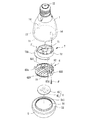
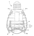
図5は本発明の実施例2の灯具の分解斜視図であり、図6は本発明の実施例2の灯具の放熱器の組み立てられた状態の断面図であり、そして図7は図6のC−C線に沿った断面図である。図5を参照すると、本発明の実施例2の灯具には少なくとも一個のハウジング1、一個の放熱器6、一個の放熱ファン7および一個の発光モジュール4が含まれる。その内、実施例2におけるハウジング1と発光モジュール4は上述した実施例1のハウジング1と発光モジュール4と略同じであるため、ここでは再び説明しない。また、実施例2においては、実施例1と同様に上述した灯具に掲示されている各部の付属構造、特徴またはその組合せを含むことができ(例えば透光カバー5などを増設する等)、これは本発明の技術分野に属する通常の常識を有するものには容易に理解できることである。
5 is an exploded perspective view of the lamp of Example 2 of the present invention, FIG. 6 is a cross-sectional view of the assembled radiator of the lamp of Example 2 of the present invention, and FIG. It is sectional drawing along CC line. Referring to FIG. 5, the lamp according to the second embodiment of the present invention includes at least one
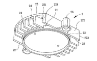
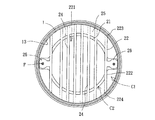
本発明の実施例2の放熱器6には一個の基板61が含まれる。基板61はハウジング1の組立口11に結合される。放熱器6には基板61の外周縁を囲むように一個の阻隔板62が設けられる。阻隔板62の内側には一個の気流通路621が形成される。阻隔板62にはハウジング1の導風壁13に向くように外側表面622が形成される。図6、7を参照すると、阻隔板62の外側表面622と導風壁13の間には一個の第一導風口C1が形成され、そして阻隔板62には気流通路621と連通する一個の凹欠部623が設けられ、凹欠部623とハウジング1の導風壁13の間には一個の第二導風口C2が形成される。その内、第一導風口C1と第二導風口C2は放熱ファン7の作動方向に応じて風進入口または風排出口として選択することができる。また、凹欠部623の相対する両側の端縁にはそれぞれ一個の翼片624が設けられる。二個の二翼片624はハウジング1の導風壁13に向いて延伸するように形成され、そして二個の翼片624は好ましくはハウジング1の導風壁13に当接するように形成され、それにより、第一導風口C1と第二導風口C2を区画することができる。
The
放熱ファン7は放熱器6に結合される。放熱ファン7には一個のファンホイール71が含まれ、ファンホイール71は一個のファンフレーム72の内部に収容されることにより、放熱ファン7のファンフレーム72は、例えばねじなどの固定部材Fと合わせて放熱器6を固定することができる。また、ファンフレーム72の周縁には一個の係止片721が設けられる。係止片721はファンフレーム72の周縁に一体になるように成形されるか、または取外し自在にファンフレーム72の周縁の片体に結合される。係止片721は放熱器6の凹欠部623の位置に位置合わせるように形成され、そして好ましくは二個の翼片624の間に位置するように形成される。
The
放熱ファン7のファンホイール71が作動する時、例えば図6、7に示すように、外部の気流を第一導風口C1を経由してハウジング1の内部と放熱器6の気流通路621まで導入した後、上記気流を第二導風口C2から再び外部へ導出することにより、発光モジュール4から生じられる熱エネルギーを補助的に駆動して排出することができる。
When the
上述した構造的特徴によると、本発明の実施例2の灯具の主要な利点は、本発明の灯具のハウジング1には他に加工を行っていかなる風進入孔または風排出孔を設ける必要がなく、そして仮に本発明の灯具を装飾板の天井板などの場所に嵌入して隠して設置する場合であっても、第一導風口C1と第二導風口C2も対応するように天井板の表面に露出するように取り付けることができるため、放熱ファン7によって気流をスムースに導入したり導出したりすることができる。さらに重要なのは、実施例2において灯具は阻隔板62によって単一の第一導風口C1と第二導風口C2を形成することができるため、風量を集中させることができる。また、例えば係止片721または翼片624などの設計によって、第二導風口C2から導出される気流がハウジング1の内部と第一導風口C1まで回流してしまうことを有効に防ぐことができるため、乱流が生じるのを防ぐことができる。
According to the structural features described above, the main advantage of the lamp of the second embodiment of the present invention is that the
上述のように、本発明の灯具によれば、ハウジング1において他にいかなる風進入孔または風排出孔も設ける必要性がなく、直接ハウジング1と放熱器2の間に形成される第一導風口C1と第二導風口C2によって風進入と風排出の機能を提供することができるため、構造の複雑性を有効に低く抑えることができるとともに、加工製造の便利性を高めることができる。また、本発明の灯具を天井板に嵌入して隠して取り付ける場合でも、第一導風口C1と第二導風口C2の設計を利用することにより、外部の空気が灯具にスムースに進出するのを確保することができ、さらに全体的な放熱効果を兼ねて高めることができるため、灯具の使用寿命を延ばすことができる。
As described above, according to the lamp of the present invention, there is no need to provide any other wind inlet hole or wind outlet hole in the
本発明は、その精神と必須の特徴的事項から逸脱することなく他のやり方で実施することができる。従って、本明細書に記載した好ましい実施例は例示的なものであり、限定を意図するものではない。 The present invention may be implemented in other ways without departing from the spirit and essential characteristics thereof. Accordingly, the preferred embodiments described herein are illustrative and not intended to be limiting.
1 ハウジング
11 組立口
12 電気の接続部材
13 導風壁
14 固定柱
2 放熱器
21 基板
22 阻隔板
221 気流通路
222 外側表面
223 第一端
224 第二端
23 螺接部
24 フィン
25 位置決め板
26 取り付け部
3 放熱ファン
31 ファンホイール
4 発光モジュール
41 発光部材
42 制御基板
5 透光カバー
51 開口部
511 外ねじ部
52 導流肩部
53 導流エアギャップ
6 放熱器
61 基板
62 阻隔板
621 気流通路
622 外側表面
623 凹欠部
624 翼片
7 放熱ファン
71 ファンホイール
72 ファンフレーム
721 係止片
8 灯具
81 ハウジング
811 第一ハウジング体
811a 風排出部
812 第二ハウジング体
812a 風進入部
82 放熱器
83 発光部材
84 放熱ファン
9 灯具
91 ハウジング
911 上ハウジング
911a 通気孔
912 下ハウジング
912a 貫穿孔
92 放熱器
93 ファン
94 LED灯ユニット
95 通気路
C1 第一導風口
C2 第二導風口
D 距離
F 固定部材
R 回転範囲
DESCRIPTION OF
Claims (15)
Applications Claiming Priority (4)
| Application Number | Priority Date | Filing Date | Title |
|---|---|---|---|
| TW100108662 | 2011-03-15 | ||
| TW100108662 | 2011-03-15 | ||
| TW100118373 | 2011-05-25 | ||
| TW100118373A TWI426214B (en) | 2011-03-15 | 2011-05-25 | Lamp |
Publications (2)
| Publication Number | Publication Date |
|---|---|
| JP2012195274A JP2012195274A (en) | 2012-10-11 |
| JP5144792B2 true JP5144792B2 (en) | 2013-02-13 |
Family
ID=45459665
Family Applications (1)
| Application Number | Title | Priority Date | Filing Date |
|---|---|---|---|
| JP2011148856A Expired - Fee Related JP5144792B2 (en) | 2011-03-15 | 2011-07-05 | Lamp |
Country Status (6)
| Country | Link |
|---|---|
| US (1) | US8610339B2 (en) |
| EP (1) | EP2500622B1 (en) |
| JP (1) | JP5144792B2 (en) |
| KR (1) | KR101311398B1 (en) |
| CN (3) | CN103499033B (en) |
| TW (1) | TWI426214B (en) |
Families Citing this family (21)
| Publication number | Priority date | Publication date | Assignee | Title |
|---|---|---|---|---|
| TWI426214B (en) * | 2011-03-15 | 2014-02-11 | Sunonwealth Electr Mach Ind Co | Lamp |
| TWI408313B (en) * | 2011-05-23 | 2013-09-11 | Sunonwealth Electr Mach Ind Co | Led lamp |
| TWI411748B (en) * | 2011-06-21 | 2013-10-11 | Sunonwealth Electr Mach Ind Co | Lamp device |
| TWI443283B (en) * | 2011-10-31 | 2014-07-01 | Edison Opto Corp | Heat sink and lamp using the same |
| CN102628555A (en) * | 2012-03-28 | 2012-08-08 | 长春希达电子技术有限公司 | Combined type printed circuit board (PCB) light source and light-emitting diode lamp containing PCB light source |
| TWI529346B (en) | 2012-05-03 | 2016-04-11 | 建準電機工業股份有限公司 | Lamp |
| KR101414650B1 (en) * | 2012-05-09 | 2014-07-03 | 엘지전자 주식회사 | Lighting apparatus |
| CN103423676B (en) * | 2012-05-18 | 2015-11-18 | 建准电机工业股份有限公司 | lamps |
| JP2013247078A (en) * | 2012-05-29 | 2013-12-09 | Nec Lighting Ltd | Lighting device |
| TWI491832B (en) * | 2012-11-16 | 2015-07-11 | Sunonwealth Electr Mach Ind Co | Lamp |
| US9200794B2 (en) | 2013-06-03 | 2015-12-01 | LEDLab, LLC | Fan cooled LED light and housing |
| KR101435857B1 (en) * | 2013-12-17 | 2014-09-23 | 엘지전자 주식회사 | Lighting apparatus |
| JP6483828B2 (en) * | 2014-08-19 | 2019-03-13 | ケイアイ グリッド カンパニー リミテッド | LED lamp |
| JP6341949B2 (en) * | 2016-04-04 | 2018-06-13 | 中村 正一 | LED lighting device |
| US9605840B1 (en) * | 2016-05-23 | 2017-03-28 | Green Inova Lighting Technology (Shenzhen) Limited | LED kit |
| FR3060202B1 (en) * | 2016-12-12 | 2019-07-05 | Aptiv Technologies Limited | DEVICE FOR DISSIPATING HEAT FROM A MULTIMEDIA CONTROL UNIT |
| CN108317411B (en) * | 2018-03-15 | 2024-03-15 | 广东小崧科技股份有限公司 | LED down lamp with high-efficient heat dissipation baffle |
| CN108870344B (en) * | 2018-08-21 | 2024-04-02 | 广东凯西欧光健康有限公司 | Heat radiation module and lamp |
| CN109404799B (en) * | 2018-12-11 | 2024-04-09 | 陈楚流 | A fan hidden ceiling light |
| CN113566129A (en) * | 2021-08-09 | 2021-10-29 | 湖南和平光电科技有限公司 | LED fluorescent tube with water conservancy diversion ventilation structure |
| WO2024153589A1 (en) * | 2023-01-16 | 2024-07-25 | Signify Holding B.V. | A lamp with active cooling |
Family Cites Families (20)
| Publication number | Priority date | Publication date | Assignee | Title |
|---|---|---|---|---|
| TW346745U (en) | 1998-03-30 | 1998-12-01 | yong-cang Chen | Structure for entrance stopper of pigeon cage |
| US7144140B2 (en) * | 2005-02-25 | 2006-12-05 | Tsung-Ting Sun | Heat dissipating apparatus for lighting utility |
| TWI262276B (en) * | 2005-11-24 | 2006-09-21 | Ind Tech Res Inst | Illumination module |
| JP2007265892A (en) * | 2006-03-29 | 2007-10-11 | Yuki Enterprise:Kk | Bulb type led lamp |
| US20080212333A1 (en) * | 2007-03-01 | 2008-09-04 | Bor-Jang Chen | Heat radiating device for lamp |
| TWI334528B (en) | 2007-06-15 | 2010-12-11 | Foxconn Tech Co Ltd | Heat sink clip and heat dissipation assembly |
| CN101368719B (en) * | 2007-08-13 | 2011-07-06 | 太一节能系统股份有限公司 | LED lamps |
| CN201246718Y (en) * | 2008-07-22 | 2009-05-27 | 大和灯具工业股份有限公司 | LED lighting device |
| US7575346B1 (en) * | 2008-07-22 | 2009-08-18 | Sunonwealth Electric Machine Industry Co., Ltd. | Lamp |
| TWM346745U (en) * | 2008-07-25 | 2008-12-11 | Forcecon Technology Co Ltd | LED Lamp with heat-dissipation toward the terminal direction |
| TWM353319U (en) * | 2008-09-17 | 2009-03-21 | Essiso Technology Co Ltd | Light emitting module and light emitting device |
| CN101749570B (en) * | 2008-12-08 | 2012-09-19 | 富准精密工业(深圳)有限公司 | LED light fitting and light engine thereof |
| JP2010153198A (en) * | 2008-12-25 | 2010-07-08 | Nec Lighting Ltd | Luminaire |
| US8057075B2 (en) * | 2009-03-13 | 2011-11-15 | Sunonwealth Electric Machine Industry Co., Ltd. | Lamp device |
| CN101858505B (en) * | 2009-04-13 | 2013-04-24 | 富准精密工业(深圳)有限公司 | Light-emitting diode (LED) lamp |
| TWM372927U (en) | 2009-08-20 | 2010-01-21 | Wei-Fan Zhuo | Lamp structure having multiple zooming effect |
| CN201547729U (en) * | 2009-11-24 | 2010-08-11 | 东莞市友美电源设备有限公司 | Heat dissipation structure of LED bulb lamp |
| CN201706458U (en) * | 2010-05-27 | 2011-01-12 | 建准电机工业股份有限公司 | Lamp and radiator thereof |
| JP5026605B1 (en) * | 2011-03-08 | 2012-09-12 | パナソニック株式会社 | Illumination device and blower for illumination device |
| TWI426214B (en) * | 2011-03-15 | 2014-02-11 | Sunonwealth Electr Mach Ind Co | Lamp |
-
2011
- 2011-05-25 TW TW100118373A patent/TWI426214B/en not_active IP Right Cessation
- 2011-06-09 CN CN201310460341.2A patent/CN103499033B/en not_active Expired - Fee Related
- 2011-06-09 CN CN201110153729.9A patent/CN102679198B/en not_active Expired - Fee Related
- 2011-06-09 CN CN2011201924244U patent/CN202118600U/en not_active Expired - Lifetime
- 2011-07-05 JP JP2011148856A patent/JP5144792B2/en not_active Expired - Fee Related
- 2011-08-16 US US13/210,861 patent/US8610339B2/en not_active Expired - Fee Related
- 2011-08-22 EP EP11006797.2A patent/EP2500622B1/en not_active Not-in-force
-
2012
- 2012-01-10 KR KR1020120002770A patent/KR101311398B1/en not_active Expired - Fee Related
Also Published As
| Publication number | Publication date |
|---|---|
| EP2500622A2 (en) | 2012-09-19 |
| US8610339B2 (en) | 2013-12-17 |
| EP2500622B1 (en) | 2015-03-18 |
| TWI426214B (en) | 2014-02-11 |
| CN103499033B (en) | 2016-01-20 |
| CN202118600U (en) | 2012-01-18 |
| KR20120105352A (en) | 2012-09-25 |
| CN102679198A (en) | 2012-09-19 |
| CN103499033A (en) | 2014-01-08 |
| KR101311398B1 (en) | 2013-09-25 |
| TW201237318A (en) | 2012-09-16 |
| EP2500622A3 (en) | 2012-10-03 |
| US20120236576A1 (en) | 2012-09-20 |
| CN102679198B (en) | 2014-03-26 |
| JP2012195274A (en) | 2012-10-11 |
Similar Documents
| Publication | Publication Date | Title |
|---|---|---|
| JP5144792B2 (en) | Lamp | |
| JP2012195273A (en) | Lamp | |
| JP5227445B2 (en) | LED lamp | |
| US8960965B2 (en) | Lamp | |
| JP5156071B2 (en) | Lamp and its radiator | |
| TWI457518B (en) | Lamp | |
| TWI414721B (en) | Lamp | |
| TWI411748B (en) | Lamp device | |
| CN103375697B (en) | Lamp fitting | |
| CN204213869U (en) | Lighting device | |
| CN103423676B (en) | lamps | |
| KR101560700B1 (en) | Heat radiating structure of LED lamp for improved heat dissipation | |
| TW201038875A (en) | Light emitting diode lamp |
Legal Events
| Date | Code | Title | Description |
|---|---|---|---|
| TRDD | Decision of grant or rejection written | ||
| A01 | Written decision to grant a patent or to grant a registration (utility model) |
Free format text: JAPANESE INTERMEDIATE CODE: A01 Effective date: 20121030 |
|
| A01 | Written decision to grant a patent or to grant a registration (utility model) |
Free format text: JAPANESE INTERMEDIATE CODE: A01 |
|
| A61 | First payment of annual fees (during grant procedure) |
Free format text: JAPANESE INTERMEDIATE CODE: A61 Effective date: 20121122 |
|
| FPAY | Renewal fee payment (event date is renewal date of database) |
Free format text: PAYMENT UNTIL: 20151130 Year of fee payment: 3 |
|
| R150 | Certificate of patent or registration of utility model |
Free format text: JAPANESE INTERMEDIATE CODE: R150 |
|
| R250 | Receipt of annual fees |
Free format text: JAPANESE INTERMEDIATE CODE: R250 |
|
| R250 | Receipt of annual fees |
Free format text: JAPANESE INTERMEDIATE CODE: R250 |
|
| LAPS | Cancellation because of no payment of annual fees |