JP5144741B2 - Driving device for driving a fixed element - Google Patents
Driving device for driving a fixed element Download PDFInfo
- Publication number
- JP5144741B2 JP5144741B2 JP2010500338A JP2010500338A JP5144741B2 JP 5144741 B2 JP5144741 B2 JP 5144741B2 JP 2010500338 A JP2010500338 A JP 2010500338A JP 2010500338 A JP2010500338 A JP 2010500338A JP 5144741 B2 JP5144741 B2 JP 5144741B2
- Authority
- JP
- Japan
- Prior art keywords
- driving device
- filler material
- dispenser
- movable
- piston
- Prior art date
- Legal status (The legal status is an assumption and is not a legal conclusion. Google has not performed a legal analysis and makes no representation as to the accuracy of the status listed.)
- Expired - Fee Related
Links
Images


Classifications
-
- B—PERFORMING OPERATIONS; TRANSPORTING
- B27—WORKING OR PRESERVING WOOD OR SIMILAR MATERIAL; NAILING OR STAPLING MACHINES IN GENERAL
- B27F—DOVETAILED WORK; TENONS; SLOTTING MACHINES FOR WOOD OR SIMILAR MATERIAL; NAILING OR STAPLING MACHINES
- B27F7/00—Nailing or stapling; Nailed or stapled work
- B27F7/02—Nailing machines
-
- B—PERFORMING OPERATIONS; TRANSPORTING
- B25—HAND TOOLS; PORTABLE POWER-DRIVEN TOOLS; MANIPULATORS
- B25C—HAND-HELD NAILING OR STAPLING TOOLS; MANUALLY OPERATED PORTABLE STAPLING TOOLS
- B25C7/00—Accessories for nailing or stapling tools, e.g. supports
-
- B—PERFORMING OPERATIONS; TRANSPORTING
- B27—WORKING OR PRESERVING WOOD OR SIMILAR MATERIAL; NAILING OR STAPLING MACHINES IN GENERAL
- B27G—ACCESSORY MACHINES OR APPARATUS FOR WORKING WOOD OR SIMILAR MATERIALS; TOOLS FOR WORKING WOOD OR SIMILAR MATERIALS; SAFETY DEVICES FOR WOOD WORKING MACHINES OR TOOLS
- B27G1/00—Machines or devices for removing knots or other irregularities or for filling-up holes
Description
本発明は、固定素子を加工面、例えば構造材に打ち込むための打ち込み装置に関する。この打ち込み装置を使用して、釘などの固定素子を木材に打ち込むものであり、また以下に限定するものではないが、とくに、本発明は、パレットおよび梱包箱(クレート)の製造、床板張りの固定、家具製造、ならびにトリムおよびアーキトレーブの固定といった用途に用いる釘打ち機に関する。 The present invention relates to a driving device for driving a fixing element into a work surface, for example, a structural material. This driving device is used to drive a fixing element such as a nail into wood, and is not limited to the following. In particular, the present invention relates to the manufacture of pallets and packing boxes (crate), and flooring. The present invention relates to a nailing machine used for fixing, furniture manufacturing, and fixing of trim and architraves.
上述のタイプの装置を用いるとき、必要な深さまで釘を打ち込む際に材料に残る凹みが、容認できないほど見映えを悪くする。仕上がりを改善するため、凹みをウッドフィラー(木製填隙材)で充填することができるが、このウッドフィラーの場合、養生後に後仕上げが必要となる。このことは、労力を伴う作業であり、生産コストが増大する。 When using a device of the type described above, the dents remaining in the material when nailing to the required depth make it unacceptably unsightly. In order to improve the finish, the dent can be filled with a wood filler (wood gap material). In the case of this wood filler, post-finishing is required after curing. This is a labor-intensive operation and increases the production cost.
本発明の目的は、加工面内に固定素子を打ち込むと同時に、固定素子が貫入する際に材料内に生ずるいかなる凹みをも充填する打ち込み装置を得ることにある。 It is an object of the present invention to obtain a driving device that fills any indentation that occurs in the material as the fixing element penetrates while simultaneously driving the fixing element into the work surface.
本発明によれば、固定素子を加工面内に打ち込む打ち込み装置であって、固定素子を加工面内に打ち込む打ち込み機構を備えた、該打ち込み装置(釘打ち機)を提供し、この打ち込み装置は、さらに、
固定素子の加工面内への突入ポイントにほぼ対応するポイントで加工面上にフィラー材料が堆積するよう構成した出口を有する、フィラー材料の供給手段と、
打ち込み装置が加工面に向かって進行するのに応じて供給手段を作動させて、加工面上にフィラー材料を堆積する、作動手段と、
打ち込み装置が加工面から後退するのに応じて、固定素子の端部上で加工面を横切るよう移動可能であり、堆積したフィラー材料を、打ち込み装置の動作の結果として加工面内に生じたいかなる凹みも平滑化しかつ充填する可動手段と
を備えたことを特徴とする。
According to the present invention, there is provided a driving device for driving a fixing element into a machining surface, the driving device (nail driving machine) having a driving mechanism for driving the fixing element into the processing surface. ,further,
A filler material supply means having an outlet configured to deposit filler material on the processing surface at a point substantially corresponding to a point of entry into the processing surface of the fixed element;
Actuating means for actuating the supply means as the driving device advances toward the work surface to deposit filler material on the work surface;
As the driving device retreats from the work surface, it can be moved across the work surface on the end of the fixed element, and the deposited filler material can be removed from any work surface that is produced as a result of the operation of the driving device. A movable means for smoothing and filling the dent is also provided.
供給手段は、本体、伸張状態に向けて押圧したピストン手段、およびリザーバを有するピストンポンプ構成のディスペンサを備えることができる。
したがって、打ち込み装置が加工面に近付くにつれてピストンは押し込まれ、フィラー材料はディスペンサ内を移動し、かつ固定素子の加工面内への突入ポイントに対応するポイントで加工面上に堆積し、これにより、使用にあたり、固定素子がフィラー材料内を通過して、フィラー材料の一部を加工面内に引き込む。ピストンポンプの動作に必要なエネルギーは、打ち込み装置の使用者が行う、打ち込み装置を加工面の近傍に接近させる動作から得られる。
Supply means, the body, pressing the piston means toward the expanded state, and can comprise a dispenser piston pump arrangement having a reservoir.
Thus, as the driving device approaches the work surface, the piston is pushed in, the filler material moves through the dispenser, and accumulates on the work surface at a point corresponding to the point of entry of the fixed element into the work surface, thereby In use, the fixing element passes through the filler material and draws a portion of the filler material into the work surface. The energy required for the operation of the piston pump is obtained from the operation performed by the user of the driving device to bring the driving device closer to the processing surface.
供給手段を作動させる作動手段は、ディスペンサの本体から突出し、加工面に接触するシャフトを有することができる。このようにして、シャフトとディスペンサの本体部分との間における接触および相対運動により、ディスペンサの動作が生じる。シャフトは、フィラー材料が出口を通過するよう、中空とすることができる。ピストン内に一方向バルブを組み込むことで、出口から供給手段へのフィラー材料の逆流を防ぐことができる。このようにして、ばね負荷の抑制されない作用の下で、ピストンの復帰運動により、フィラー材料のリザーバからの流入を誘発することができる。 The actuating means for actuating the supply means can have a shaft that protrudes from the body of the dispenser and contacts the work surface. In this way, contact and relative movement between the shaft and the body portion of the dispenser cause the operation of the dispenser. The shaft can be hollow so that the filler material passes through the outlet. By incorporating a one-way valve in the piston, the backflow of filler material from the outlet to the supply means can be prevented. In this way, the inflow of the filler material from the reservoir can be induced by the return movement of the piston under the action of unrestrained spring loading.
ピストンポンプ構成のディスペンサは、ピストン手段の移動行程中にピストン手段(11)によりカバーされる逃がし孔(スピルポート)を有し、ピストン手段の初期移動の際には、逃がし孔が開口し、フィラー材料がリザーバに逆流するとともに、初期移動後のさらなる移動の際に、ピストン手段が逃がし孔を閉鎖し、出口からフィラー材料を分注する構成とする。リザーバは、可撓性材料で形成することができ、例えば剛性フレームに収容することができる。このことにより、リザーバは、ディスペンサの動作に関連する容積変化を調整することができ、またリザーバからガスを排出することが可能となる。 The dispenser having the piston pump configuration has an escape hole (spill port) covered by the piston means (11) during the movement of the piston means, and the escape hole is opened during the initial movement of the piston means. As the material flows back into the reservoir, the piston means closes the relief hole and dispenses the filler material from the outlet during further movement after the initial movement. The reservoir can be formed of a flexible material and can be housed in a rigid frame, for example. This allows the reservoir to adjust for volume changes associated with the operation of the dispenser and to discharge gas from the reservoir.
打ち込み装置の前進移動中に、加工面との接触の結果、供給手段が動作する構成とすることができる。 During the forward movement of the driving device, the supply means can operate as a result of contact with the machining surface.
出口の軸線方向を、の前記打ち込み装置から加工面への固定素子移動方向に対して傾斜させることができる。出口の軸線方向は、固定素子の移動方向に交差させることができる。このとき、出口は、打ち込み装置が動作中、固定素子の経路にほぼ位置する位置で加工面上にフィラー材料を分注する。このようにして、固定素子の経路に対する出口の傾斜角とともに、ディスペンサピストンのストロークは、加工面を横切って出口が移動する距離を決定する。このような移動によれば、打ち込み装置の動作により生じたいかなる凹みにもフィラー材料を落し込むよう、フィラー材料を払拭することができる。 The axial direction of the outlet can be inclined with respect to the moving direction of the fixed element from the driving device to the processing surface. The axial direction of the outlet can intersect the moving direction of the fixed element. At this time, the outlet dispenses the filler material on the work surface at a position substantially located in the path of the fixing element while the driving device is operating. Thus, the stroke of the dispenser piston, as well as the angle of inclination of the outlet with respect to the path of the fixed element, determines the distance that the outlet moves across the work surface. According to such movement, the filler material can be wiped off so as to drop the filler material into any dent caused by the operation of the driving device.
供給手段の出口は、前記打ち込み装置の前記加工面(36)からの後退に応じて移動可能にし、この移動により堆積したフィラー材料がいかなる凹みをも充填するようにする。この場合、作業後に打ち込み装置が加工面から加工面に直交する方向に上昇するとき、例えば押圧ばねの作用の下に、出口の動作は加工面との接触を維持し、これにより、加工面内に生じたいかなる凹みをも掃引しかつ充填することができる。 The outlet of the supply means is movable in response to the retraction of the driving device from the working surface (36) so that the filler material deposited by this movement fills any depressions. In this case, when the driving device ascends in the direction perpendicular to the machining surface after the work, for example, under the action of a pressing spring, the outlet movement maintains contact with the machining surface, thereby allowing the Any dents produced in the can be swept and filled.
代案として、打ち込み装置の後退に応じて移動可能な可動手段は、ワイパーおよびローラから選択するものとすることができる。可動手段は、打ち込み装置が加工面に向かって前進する際に、可動手段が、打ち込み装置から加工面へ向かう固定素子の移動方向を横断して延在する第1位置から、固定素子の移動方向から外れる第2位置に後退し、また打ち込み装置が加工面から後退する際に、可動手段が第2位置から第1位置に前進して、堆積したフィラー材料がいかなる凹みをも充填するように、移動可能とすることができる。可動手段が第1と第2位置との間を移動するとき、可動手段は、最初に加工面に向かって移動し、その後に加工面から離れるよう移動する構成とする。可動手段は、円弧状経路に沿って移動可能とすることができる。 As an alternative, the movable means that can move in response to the retraction of the driving device can be selected from wipers and rollers. The moving means moves in the direction of movement of the fixed element from the first position where the moving means extends across the moving direction of the fixed element from the driving apparatus toward the processing surface when the driving apparatus advances toward the processing surface. So that when the driving device is retracted from the work surface, the movable means is advanced from the second position to the first position so that the deposited filler material fills any depressions. It can be movable. When the movable means moves between the first and second positions, the movable means first moves toward the processing surface and then moves away from the processing surface. The movable means can be movable along an arcuate path.
可動手段は、カム機構、ラックおよびピニオン組立体、およびにウォーム駆動から選択した作動手段であって、打ち込み装置が加工面に対して前進および後退するとき作動する作動手段によって移動可能にすることができる。 The movable means is an actuating means selected from a cam mechanism, a rack and pinion assembly, and a worm drive, and is movable by an actuating means that is actuated when the driving device moves forward and backward relative to the work surface. it can.
可動手段は、可撓性材料、例えば弾性材料で形成することができる。また、可動手段は、低摩擦係数を有する材料で形成する、および/または低摩擦係数を有する材料を用いて可動手段を被覆することができる。 The movable means can be formed of a flexible material, such as an elastic material. Also, the movable means can be formed of a material having a low coefficient of friction and / or can be coated with a material having a low coefficient of friction.
ワイパーには、可撓性を増大する、くびれ領域を設けることができる。 The wiper can be provided with a constricted region that increases flexibility.
押圧(バイアス)手段を設け、可動手段を加工面に向けて押圧する構成とすることができる。 A pressing (bias) means may be provided, and the movable means may be pressed toward the processing surface.
フィラー材料は、リザーバ内ではほぼ液体の状態から、分注後に固体状態に変化するよう調整することができる。出口内でフィラー材料が硬化するのを防ぐため、内圧の作用下でフィラー材料を通過させるが、内圧作用がない場合には気密封止を生ずる一方向バルブを出口に組み込む。このようにして、順次の使用間に出口をシールし、空気および湿気の侵入、ならびにフィラー材料における揮発成分の損失を防止する。 The filler material can be adjusted to change from a substantially liquid state in the reservoir to a solid state after dispensing. In order to prevent the filler material from curing in the outlet, a one-way valve is incorporated at the outlet that allows the filler material to pass under the action of internal pressure but creates a hermetic seal when there is no internal pressure action. In this way, the outlet is sealed between successive uses to prevent air and moisture ingress and loss of volatile components in the filler material.
ガードを設け、このガードにより加工面上に堆積したフィラー材料を包囲する構成とすることができる。ガードは、少なくとも部分的に可撓性を有するものとする。固定素子を加工面内に打ち込むとき、出口は、ガードの一部をなすものとする。このようなガードは、固定素子がフィラー材料を高速で通過する時に、フィラー材料が飛散するのを防ぐのに役立つ。 A guard may be provided, and the filler material deposited on the processed surface may be surrounded by the guard. The guard is at least partially flexible. When the fixing element is driven into the machining surface, the outlet is part of the guard. Such guards help prevent the filler material from splashing as the stationary element passes through the filler material at high speed.
可動手段は、打ち込み装置の可動の脚部内に配置することができる。加工面に接触するよう構成した脚部の表面を滑り止め面として設ける。可動の脚部は、ほぼU字状とする。出口は、U字状の脚部の開口側内に突入する。 The movable means can be arranged in a movable leg of the driving device. The surface of the leg part configured to contact the processing surface is provided as a non-slip surface. The movable leg is substantially U-shaped. The outlet enters the opening side of the U-shaped leg.
フィラー材料用のディスペンサの全体を、ディスポーザブル(使い捨て)物品として形成することができ、この物品はフィラー材料を使い切ったときに交換する。このようなディスポーザブル部材は、ガードも含む。あるいは、ディスペンサは、フィラー材料のディスポーザブルリザーバをディスペンサの残りの部分に取り付けるよう組み込むことができる。ディスペンサ自体は、いくつかのリザーバを取り付けた後に交換することができる。
本発明のよりよい理解を得るため、また本発明をどのように実施するかをより明確にするため、添付の図面につき、本発明の実施形態を例示として説明する。
The entire dispenser for the filler material can be formed as a disposable article that is replaced when the filler material is used up. Such a disposable member also includes a guard. Alternatively, the dispenser can be incorporated to attach a disposable reservoir of filler material to the remainder of the dispenser. The dispenser itself can be replaced after installing several reservoirs.
In order to provide a better understanding of the present invention and to clarify how to implement the present invention, embodiments of the present invention will be described by way of example with reference to the accompanying drawings.
図1〜図3は、従来の釘打ち機にとって重要な特徴を図示しており、釘43を細条状に形成し、この釘43は、取付孔48によって保持するマガジン(図示せず)から、ガンバレル35における溝孔45を経て供給する。ピストン41の上面に加わるガス圧により、ピストン41で打ち込みピン42を動作させ、第1トリガー機構(図示せず)によってガス流を調整する。第2に、連動トリガー機構を可動脚部44に取り付け、これにより、釘打ち機が作動するために、双方のトリガー機構が動作しなければならないようにする。このことは、既知の安全策であり、釘打ち機の不慮の発射を防止する。
1 to 3 illustrate important features for a conventional nailing machine, in which a nail 43 is formed in a strip shape, and this nail 43 is removed from a magazine (not shown) held by a mounting hole 48. FIG. , And supplied through a slot 45 in the
図2に示すように、脚部44は、伸張位置に向けてばね負荷を受ける。図3に示すように、トリガー機構を作動させるためは、脚部44を押し下げ、釘打ち機バレル35の端部を木製ブロック36に近接させなければならない。
As shown in FIG. 2, the
本発明によれば、2個のトリガー機構が作動する時、打ち込みピン42は、バレル35内のオリフィス47を通って下降し、ディスペンサノズル34は、オリフィス47の軸線、したがって、打ち込むときに釘43の運動軸線に交差する傾斜ライン上に位置する。図2に示すように、ディスペンサノズル34は、伸張位置に向けてばね負荷を受ける。ディスペンサノズル34の端部にシュー32を取り付け、ディスペンサノズルから木製ブロック36の表面にフィラーを案内する。釘打ち機を木のブロック36に近接させ、脚部44を押し下げかつ連動トリガーを作動することで、この動作がディスペンサを作動し(図示せず)、ディスペンサノズル34から、打ち込む釘の経路上における木製ブロック36の表面にフィラー材料を堆積することで、釘43がフィラー材料内を通過しかつフィラー材料の一部を木製ブロック36内に引き込む。
According to the present invention, when the two trigger mechanisms are activated, the driving
フィラー材料は、分注前のほぼ液体状態から、分注後の固体状態に変化するよう設計する。 The filler material is designed to change from a substantially liquid state before dispensing to a solid state after dispensing.
図4〜図7は、釘打ち機バレル35を木製ブロック36に対して垂直に動かすときのディスペンサノズル34およびシュー32の運動を示す。釘位置31は、釘の打込み予定位置を示す。図4は、初期的に、ディスペンサからのばね力(図4〜図7には図示せず)により、木製ブロック36に対してシュー32が圧着する状態を示す。シュー32は、釘位置31をカバーする。釘打ち機が図5に示す位置に移動するにつれ、ノズルは、傾斜ガイド33に沿って移動し、シュー32は、釘位置31から離れて木製ブロック36の表面を横切るよう移動する。ノズル34の動作によりディスペンサポンプが作動し、釘位置31またはその近傍における木製ブロック36の表面にフィラー材料を堆積させる。図6は、図5よりもバレル35が木製ブロック36に接近した状態を示しており、シュー32による釘位置31のカバーがより外れた状態になる。図7は、脚部44(図4〜図7には図示せず)が連動トリガーを作動させ、釘打ち機の発射準備ができるポイントでノズル34を完全に押し下げられた状態を示す。ディスペンサは、木製ブロック36の表面に必要量のフィラーを送出する。つぎに、釘打ち機が作動し、木製ブロック36内に釘を発射する。発射後、釘打ち機が木製ブロック36から離れるにつれ、シュー32は、木製ブロック36に接触したまま釘位置31上で摺動して戻る。シュー32の動作により、釘位置31近傍のフィラー材料を、木製ブロック36における釘が形成した空洞(窪み)内に流入させて平滑化する。
4-7 illustrate the movement of the
図8および図9は、フィラーディスペンサの断面図および側面図を示す。図4〜図7につき説明したノズル34にディスペンサ出口21を接続する。ディスペンサ出口21は中空管とし、この中空管は、復帰ばね19に取り付けたピントル15に堅固に取り付ける。ピントル15をディスペンサ出口21に連結し、ピストン11がピントル15に衝合せず、したがって通路を封止しない場合に、ピントルとディスペンサ出口との間における環状の隙間を経てフィラー材料が流通できるようにする。ピストン11を摺動可能にディスペンサ口21に取り付け、ピストンばね18によりピントル15の背面にピストン11を圧着させ、ディスペンサ10の本体内のフィラーとディスペンサ出口21との間の接続を閉鎖する。ディスペンサ10本体内の圧力がピストンばね18によって決まる圧力を越えるとき、ピストン11はピントル15の背部から離れるよう移動し、フィラー材料がディスペンサ出口21を通過することができる。逃がし孔20および入口14をリザーバ25(図12に図示)に接続する。ディスペンサ出口21を押し下げることで、ピストンばね18は、ピストン11をディスペンサ10本体の下方に動かす。ピストン11は、ディスペンサ出口21を封止するピントル15に接触する。この動作により、フィラー材料は、逃がし孔20を通ってディスペンサ本体10から流出し、リザーバ25に戻る。着座部16に係合するチェックボール12は、入口14からの逆流を防止する。
8 and 9 show a cross-sectional view and a side view of the filler dispenser. The
図10および図11は、ディスペンサ出口21の移動における極限位置を示す。ディスペンサ出口21が図10に示す位置から図11に示す位置に移動することで、ピストン11を、逃がし孔20上に移動させてカバーする。逃がし孔20がカバーされずにいる間、ピストン11の動作によりディスペンサ10本体内のフィラー材料を逃がし孔20から押出し、また同時に、ピストン11は、ディスペンサ出口21を閉鎖した状態を維持するピントル15と接触した状態に留まる。ピストン11が逃がし孔20をカバーしているとき、逃がし孔を経るリザーバ25への逆流は防止される。また、吸気孔14を経る逆流は、チェックボール12によって防止する。ディスペンサ出口21がさらに移動することにより、ディスペンサ本体10の内圧が上昇し、ピストンばね18に圧着するようピストン11を変位させ、ピストン11とピントル15の背面との間の封止が断たれる。図11に示す位置までのディスペンサの残りのストロークにわたり、フィラー材料がディスペンサ出口21を通って移動する。したがって、分注されるフィラー材料の量は、ピストン11の断面積およびディスペンサ出口21のストローク端部に対する逃がし孔20の位置の関数である。さらに、逃がし孔20をカバーするまでフィラー材料の送給は開始されず、したがって、ストロークの初期に送給は生ずることがなく、このため、ディスペンサ出口21との不慮の接触がフィラー材料の送給を生ずることはない。
10 and 11 show the extreme positions in the movement of the
図12は、リザーバ25に接続したディスペンサ本体10を示す。リザーバは、理想的には、リザーバ内のフィラー材料の量が変化するにつれて、圧力変化なしに、形状および容積が容易に変化できる可撓性かつ非伸縮性で構成する。可撓性リザーバ25は、好適には、防護のため、堅固なフレームまたは容器内に収容する。
FIG. 12 shows the
図13〜図16は、ワイパー52を組み込み、図1〜図12につき説明するシュー32の機能を付与するフィラーディスペンサシステムを示す。ワイパー52は、ディスペンサシステムの本体55に取り付けたリンク53によって支持し、このリンク53を釘打ち機バレル35に取り付ける。リンク53およびワイパー52の構成配置は、ワイパーの先導端縁を規制して、ディスペンサ10の軸線に接近する円弧状経路を追従させる。このワイパー52を、図16に示す極限位置に向けてばね付加する。釘打ち機が木製ブロック36に接近するとき、ワイパーは、まず木製ブロック36の表面に接触し、これにより、先導端縁が釘位置31の位置をカバーする。図10および図11に相当する位置に近接するよう釘打ち機を押し下げるとき、ワイパー32は、釘位置31を横断して釘位置31から離れるよう後退し、ワイパー52の内面が窪み57内でディスペンサノズル51に接触する。さらに、釘打ち機が図13の位置に移動することにより、ディスペンサノズル51に作用して、ワイパー52内の窪み57から接続流路を経て、木製ブロック36の表面に若干量のフィラー材料を押し出して送給する。図13の状態では、釘打ち機は、発射準備が整い、脚部44(図13には図示しない)における連動トリガーに連結される。フィラー材料を通過するよう釘を発射した後、釘打ち機を、木製ブロック36の表面から離れるよう表面に直交する方向に持ち上げるとき、ワイパー52は、ばね(図示せず)によって表面に接触した状態を維持する。ワイパー52は、釘位置31に向かって復帰移動し、釘位置31での釘打ち動作により生じた凹みにフィラー材料を落し込んで平滑化する。ディスペンサおよびリザーバと共に、本体55、リンク53、ならびにワイパー52は、消耗の際に部分的にまたは全体的に取り替える使い捨て物品として安価に製造することができる。この設計によれば、平滑化動作用のストロークが不必要なことからストロークを大幅に短縮することができるため、ディスペンサを簡素化し、逃がし孔および戻り通路を省くことができる。
FIGS. 13-16 illustrate a filler dispenser system that incorporates a
図17〜図19は、可撓性ガード58をワイパー52に装着する状況を示す。釘を発射する瞬間に、可撓性ガード58が、ワイパー52と共に、木製ブロック36の表面のフィラー材料を包囲する。可撓性ガード58は、フィラー材料を収容し、釘がフィラー材料に高速で貫入するときの飛散を防ぐ。可撓性ガードは、上述のディスポーザブルシステムの一部とすることができる。
17 to 19 show a situation in which the
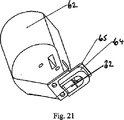
図20および図21は、図1〜図12につき説明したディスペンサシステム用のガードシステムを示す。スプラッターガード64をフィラーディスペンサ本体62に取り付けたブラケット65に取り付ける。これら構成部材は、ディスペンサ、リザーバ、およびフィラー材料とともに、ディスポーザブルシステムの一部を形成することができる。ディスペンサノズル34が完全に押し下がった位置にあるとき、ディスペンサノズル34におけるシュー32は、ほぼC字状のスプラッターガードの開放している端部間の隙間を埋める。釘打ち機を発射し、釘がフィラー材料に衝突するとき、スプラッターガードは、木製ブロック36の表面に対して、釘位置31の周りを完全に包囲するシールを形成する。
20 and 21 show a guard system for the dispenser system described with reference to FIGS. The
図22および図23は、未使用の期間中にディスペンサ内でフィラー材料が硬化するのを防ぐ一方向バルブとして作用する構成簡単な封止システムを示す。これら図面は、固定アーマチュア82に取り付けたディスペンサ本体10を示し、この固定アーマチュア82を通過するディスペンサ出口21をシュー32に取り付ける。この構成において、シューは、側壁にオリフィス88を有するほぼ円筒形状にし、このオリフィスからフィラー材料を送給する。弾性スリーブ84をシュー32の円筒形表面上で摺動させ、弾性スリーブ84の材料を緊張状態にする。シュー32の内部からの陽圧により、スリーブをシューの表面から持ち上がらせ、フィラー材料を流出させる。空気、埃および湿気がオリフィス88から侵入するのを防止し、またフィラー材料の揮発性成分からの低圧蒸気がオリフィスから漏れることができないようにすることで、フィラー材料の早期硬化を防止する。
22 and 23 show a simple sealing system configured to act as a one-way valve to prevent the filler material from curing in the dispenser during periods of unused. These drawings show the
多くの変更を、本発明から逸脱することなく、行うことができる。例えば、ディスペンサは異なるバルブおよびピストンデザインを使用でき、またはスプラッターガードシステムを釘打ち機バレルに永久的に固着することができる。 Many modifications can be made without departing from the invention. For example, the dispenser can use different valve and piston designs, or the splatter guard system can be permanently affixed to the nailer barrel.
図24〜図27に示す釘打ち機は、ノズル51を有しかつディスペンサ本体62に取り付けた、ディスペンサ10を有する。ノズル51は以下のように構成する、すなわち、釘打ち機を加工面(図示せず)に向けて移動して動作させるとき、ノズルが加工面に係合し、またディスペンサ10をディスペンサ本体62内に後退させ、これにより所定量のフィラーを加工面上で釘の経路内(図示せず)に分注するように構成する。
The nailing machine shown in FIGS. 24 to 27 has a
従来のように、釘打ち機本体に向かって上方に突出する支柱46に脚部44を取り付ける。上述のように、脚部44は、釘打ち機の本体に対して相対移動可能であり、伸張位置に向けて押圧される。加工面に接触する結果として脚部が後退するとき、従来通り、釘打ち機用の作動機構の一部として、第2の連動トリガー機構(図示せず)が得られる。
As in the prior art, the
カムアクチュエータ90を釘打ち機本体55の所定位置に設け、この場合、脚部44が後退するにつれて、脚部上に設けたカム91と係合するように設ける。脚部44は、ほぼU字状をしており、加工面上の釘を打ち込む領域を取り囲む。脚部44の下面に滑り止め表面、例えば中程度〜高程度のショア硬度を有する熱可撓性エラストマー、を設け、意図した領域に釘を確実に打ち込むことができるようにする。滑り止め表面に隆起を設けることで、加工面に対するグリップを向上することができる。必要に応じて、滑り止め表面を取り外し、新たな材料と交換することで、釘を打ち込む加工面との十分な係合を確実に維持することができる。ディスペンサのノズル51は、脚部が後退するにつれてU字状の脚部44の開口側内に突入し、これにより、所望の位置にフィラーを分注する。
The cam actuator 90 is provided at a predetermined position of the nailing
ワイパーブレード組立体92をU字状の脚部44内に取り付け、またこのワイパーブレード組立体92は、キャリア94に取り付けたワイパーブレード93を有する。ワイパーブレードは、低摩擦係数を有する可撓性、または好適には弾力性の材料、例えばポリテトラフルオロエチレン(PTFE)、シリコーンまたはポリプロピレン材料で形成し、ワイパーブレードが加工材上を滑らかに通過できるようにする。必要に応じて、ブレード93には、摩擦係数を減少させる表面コーティングを設けることができる。ワイパーブレード93は、加工面を繰り返し移動する結果として摩耗し易く、また例えば加工面の凹凸に接触する結果として損傷する恐れがある。したがって、ワイパーブレードは、少なくとも交換可能なコンポーネントとし、必要であればいつでも容易に取り外し、また新しいコンポーネントと交換できるようにする。このワイパーブレード93ワイパーブレード組立体92に、押圧(バイアス)手段、例えばコイルばねまたはねじりばねにより取り付けることができ、ワイパーブレードの自由端縁を加工面の方向に押圧する。
A
例えば、キャリアを脚部44内に摺動可能に、例えばキャリアがほぼ側方に、ディスペンサノズル51に対して接近および遠ざかることを可能にする窪み95内で摺動可能に取り付ける。窪み95は、ディスペンサノズル51に最も近接する領域でほぼ側方に延在し、しかし、各端部では上方に向かって(加工面から離れるよう)傾斜する。これにより、行程の各終了部分において、加工面から少なくとも部分的に、ワイパーブレードを持ち上がる。このような動作は、湾曲した、または円弧状の経路に沿う移動により都合よく得られる。
For example, the carrier is slidably mounted within the
脚部44を貫通する回転可能シャフト96にカム91を取り付ける。また、カムの回転に応じて回転可能となるよう、脚部44内の回転可能シャフトに、作動アーム97の一の方端部を取り付ける。作動アーム97の他方の端部をキャリア94に回転可能に連結する。押圧手段、例えば図示したねじりばね98またはコイルばねを設け、キャリア94およびワイパーブレード93をディスペンサノズル51の方向押圧する。
A
図27に明示するように、ワイパーブレード93には、ワイパーブレードの屈曲を容易にする、くびれ領域99を形成する。
As clearly shown in FIG. 27, the
図24〜図27に示す釘打ち機の使用にあたり、使用者が加工面に向けて加工面にほぼ直交する方向に釘打ち機を押し込むにつれて、カムアクチュエータ90がカム91に係合し、カムを図24で見て時計回りに回転させる。カム91の回転により、シャフト96および作動アーム97が連動して回転することで、キャリア94および付属のワイパーブレード93をディスペンサノズル51から離れる方向に移動させ、また一連の行程の終了時に加工面から少なくとも部分的にワイパーブレード93を持ち上げる。
When the nailing machine shown in FIGS. 24 to 27 is used, as the user pushes the nailing machine in a direction substantially perpendicular to the machining surface toward the machining surface, the cam actuator 90 engages with the
同時に、ディスペンサノズル51が加工面に接触し、押し下げることで、釘を打ち込むべき領域で加工面上に、ビードの形態をした所定量のフィラーを分注する。
At the same time, the
脚部44が加工面に接触した状態で、釘打ち機を加工面に対する所定距離範囲内に移動したとき、釘打ち機は発射準備が整い、普通のトリガー(図示せず)を押し下げることで釘を発射する。釘は、釘打ち機から抜け出て、ビード状のフィラーを通過して加工面内に突入し、フィラー材料の一部を加工面内に引き込む。
When the nailing machine is moved within a predetermined distance range with respect to the machining surface with the
次に、使用者が加工面からこの加工面に直交する方向に釘打ち機を持ち上げ、カムアクチュエータ90が後退することにより、カム91がねじりばね98の押圧力の下で回転することで、キャリア94およびワイパーブレード93をディスペンサノズル51の方向に移動させ、再度、一連の行程の終了時にワイパーブレード93を少なくとも部分的に加工面から持ち上げる。
Next, the user lifts the nailing machine from the machining surface in a direction perpendicular to the machining surface, and the cam actuator 90 moves backward so that the
ワイパーブレード93がディスペンサノズル51に向かって移動するにつれて、キャリア94は窪み95に沿って走行するため、加工面に接近するとともにディスペンサノズルに向かって移動する。ワイパーブレードの下降移動と相まって、ワイパーブレードが加工面に対して角度が付くよう(すなわち、実質的に直角ではない角度が付くよう)、くびれ領域においてワイパーブレード93が屈曲することにより、「スミアリング(擦り付け)」動作を生じ、この動作により最初に釘ヘッドが加工面内に進入するとき釘ヘッドにより形成された凹み内にフィラー材料を落し込み、次に凹みから盛り上がっている過剰のフィラー材料を除去する。
As the
くびれ領域による可撓性と組み合わさった、一連の行程の終了時にワイパーブレード93の持ち上がり動作は、行程の各方向の終了時に動きの方向が変化したとき、ワイパーブレードがある角度付き方向から他の方向に容易に「フリップする(翻る)」ことを可能にし、ワイパーブレードがいかなる凹凸にも引っ掛かることなく加工面上をより容易に通過することを可能にする。つまり、くびれ領域99は、ヒンジの形態として作用する。このように、ワイパーブレード93の下方端縁は、運動の方向に関係なく、常に上側領域を追尾する。
The lifting movement of the
カム91および作動アーム97を使用することは重要ではなく、代替機構を用使用して、釘打ち機の下降運動をワイパーブレード組立体92の横断運動に伝達することができ、例えばラックおよびピニオン組立体またはウォーム駆動を使用することができるということを理解されたい。さらに、ワイパーブレード93を、付加的にまたは代替的に、下側端縁の周りに回動可能にし、ブレード表面をフィラー材料に係合させ、また釘ヘッドにより生じ加工面の凹みにフィラー材料を押し込むようにすることができる。代案として、ワイパーブレードを、他の手段、例えば下方押圧ローラ等で代替し、釘ヘッドにより生じた加工面の凹み内にフィラー材料を落し込むことができる。
The use of
Claims (15)
前記固定素子の前記加工面内への突入ポイント(31)にほぼ対応するポイントで前記加工面上にフィラー材料が堆積するよう構成した出口(34)を有する、フィラー材料の供給手段(10)と、
前記打ち込み装置が前記加工面に向かって進行するのに応じて前記供給手段を作動させて、前記加工面上に前記フィラー材料を堆積し、前記固定素子を前記加工面に打ち込むとき、前記固定素子が前記フィラー材料を通過するようにした、作動手段(21,51)と、
前記打ち込み装置が前記加工面から後退するのに応じて、前記固定素子の端部上で前記加工面を横切るよう移動可能であり、堆積した前記フィラー材料を、前記打ち込み装置の動作の結果として前記加工面内に生じたいかなる凹みも平滑化しかつ充填する可動手段(32,52,93)と
を備えたことを特徴とする打ち込み装置。In the driving device for driving the fixing element (43) into the processing surface (36), the driving device includes a driving mechanism (41, 42) for driving the fixing element into the processing surface.
A filler material supply means (10) having an outlet (34) configured to deposit filler material on the processed surface at a point substantially corresponding to the entry point (31) of the fixing element into the processed surface; ,
When the driving device is operated toward the processing surface to operate the supply means to deposit the filler material on the processing surface and to drive the fixing element into the processing surface, the fixing element Actuating means (21, 51) adapted to pass through the filler material ;
As the driving device retracts from the processing surface, the driving device is movable across the processing surface on the end of the fixing element, and the deposited filler material is removed as a result of the operation of the driving device. A driving device characterized by comprising movable means (32, 52, 93) for smoothing and filling any dents produced in the work surface.
Applications Claiming Priority (1)
| Application Number | Priority Date | Filing Date | Title |
|---|---|---|---|
| PCT/GB2007/001074 WO2008117000A1 (en) | 2007-03-23 | 2007-03-23 | Device for driving a fixing element |
Publications (2)
| Publication Number | Publication Date |
|---|---|
| JP2010522094A JP2010522094A (en) | 2010-07-01 |
| JP5144741B2 true JP5144741B2 (en) | 2013-02-13 |
Family
ID=38769678
Family Applications (1)
| Application Number | Title | Priority Date | Filing Date |
|---|---|---|---|
| JP2010500338A Expired - Fee Related JP5144741B2 (en) | 2007-03-23 | 2007-03-23 | Driving device for driving a fixed element |
Country Status (6)
| Country | Link |
|---|---|
| US (1) | US20130186928A1 (en) |
| EP (1) | EP2129502A1 (en) |
| JP (1) | JP5144741B2 (en) |
| CN (1) | CN101687336A (en) |
| AU (1) | AU2007350184A1 (en) |
| WO (1) | WO2008117000A1 (en) |
Families Citing this family (4)
| Publication number | Priority date | Publication date | Assignee | Title |
|---|---|---|---|---|
| EP2234767B1 (en) * | 2008-01-29 | 2018-10-17 | Nail Seal Limited | Recess filling apparatus |
| CN106671220B (en) * | 2017-02-27 | 2022-06-21 | 青岛世纪乾源展示用品有限公司 | Semi-automatic wooden case nailing machine |
| CN107097308B (en) * | 2017-06-02 | 2019-05-24 | 丁文海 | A kind of architectural engineering self-retaining plate nailing device |
| CN111152162A (en) * | 2020-02-26 | 2020-05-15 | 建德席次机械设备有限公司 | Motor-driven self-filling nail-shooting hammer |
Family Cites Families (11)
| Publication number | Priority date | Publication date | Assignee | Title |
|---|---|---|---|---|
| DE1248906B (en) * | 1965-12-15 | 1968-03-14 | 6320 Aisfeld Karl Unger | Portable pneumatic wooden dowel shooting device with dowel feed |
| CH497948A (en) * | 1967-11-02 | 1970-10-31 | Bilek Anton | Portable, pneumatic wood dowel insertion device |
| US4146339A (en) * | 1977-04-04 | 1979-03-27 | Fleming Caster Industries, Inc. | Apparatus for filling staple depressions |
| SU891438A1 (en) * | 1977-09-21 | 1981-12-23 | Экспериментальное Проектно-Конструкторское Бюро Всесоюзного Объединения "Союзлесдрев" | Appparatus for pressing-in tenons |
| JPS59182071A (en) * | 1983-03-31 | 1984-10-16 | 松下電工株式会社 | Nail driver |
| JPS6279976A (en) * | 1985-09-30 | 1987-04-13 | マルケイ木工株式会社 | Method for nailing wood nail |
| US5143572A (en) * | 1990-02-23 | 1992-09-01 | Hatch J Mel | Dowel shooting apparatus |
| US5092508A (en) * | 1990-11-14 | 1992-03-03 | Amaro Vigil Rio | Compressed air nail machine |
| JPH07237149A (en) * | 1994-02-28 | 1995-09-12 | Sekisui Chem Co Ltd | Automatic nail driver and nail driving method by this driver |
| US5947362A (en) * | 1997-10-09 | 1999-09-07 | Omli; Allan T. | Fastener driver cap feeder assembly |
| EP2234767B1 (en) * | 2008-01-29 | 2018-10-17 | Nail Seal Limited | Recess filling apparatus |
-
2007
- 2007-03-23 JP JP2010500338A patent/JP5144741B2/en not_active Expired - Fee Related
- 2007-03-23 CN CN200780053057A patent/CN101687336A/en active Pending
- 2007-03-23 AU AU2007350184A patent/AU2007350184A1/en not_active Abandoned
- 2007-03-23 EP EP07712960A patent/EP2129502A1/en not_active Withdrawn
- 2007-03-23 WO PCT/GB2007/001074 patent/WO2008117000A1/en active Application Filing
- 2007-03-23 US US12/532,721 patent/US20130186928A1/en not_active Abandoned
Also Published As
| Publication number | Publication date |
|---|---|
| EP2129502A1 (en) | 2009-12-09 |
| US20130186928A1 (en) | 2013-07-25 |
| CN101687336A (en) | 2010-03-31 |
| JP2010522094A (en) | 2010-07-01 |
| WO2008117000A1 (en) | 2008-10-02 |
| AU2007350184A1 (en) | 2008-10-02 |
Similar Documents
| Publication | Publication Date | Title |
|---|---|---|
| TWI374797B (en) | Fastener driving device | |
| JP5144741B2 (en) | Driving device for driving a fixed element | |
| US7255256B2 (en) | Finish nailer with contoured contact trip foot | |
| RU2518826C2 (en) | Pneumatic drive machine | |
| EP3022131B1 (en) | Dispenser and method for dispensing fluids from a fluid container | |
| CA2794982C (en) | Flanged fuel cell and locating structure for combustion tool | |
| JP2008018484A (en) | Driving machine | |
| JP2007537942A (en) | Non-ventilated liquid product dispenser | |
| US6460739B1 (en) | Dispenser | |
| JP4761257B2 (en) | Fastener driving machine | |
| US8152039B2 (en) | Recess filling apparatus | |
| JP5748104B2 (en) | Driving machine | |
| JP5286939B2 (en) | Driving machine | |
| GB2440590A (en) | Nail gun with means to deposit filler material | |
| PL193683B1 (en) | Hand holdable pump spray apparatus | |
| RU2004137288A (en) | DISPENSER FOR PORTIONAL DISPOSAL OF PASTE MASSES | |
| JP5575687B2 (en) | Trigger type ejector | |
| JP3840865B2 (en) | Driving machine | |
| JP4062538B2 (en) | Driving machine | |
| US20200324398A1 (en) | Clinch fastener system | |
| JP5628730B2 (en) | Trigger type ejector | |
| JP3846538B2 (en) | Trigger valve device for driving machine | |
| JP4457348B2 (en) | Driving machine | |
| JP2014046279A (en) | Trigger type ejection device | |
| JP2011194543A (en) | Driving machine |
Legal Events
| Date | Code | Title | Description |
|---|---|---|---|
| A131 | Notification of reasons for refusal |
Free format text: JAPANESE INTERMEDIATE CODE: A131 Effective date: 20120522 |
|
| A521 | Request for written amendment filed |
Free format text: JAPANESE INTERMEDIATE CODE: A523 Effective date: 20120817 |
|
| TRDD | Decision of grant or rejection written | ||
| A01 | Written decision to grant a patent or to grant a registration (utility model) |
Free format text: JAPANESE INTERMEDIATE CODE: A01 Effective date: 20121113 |
|
| A01 | Written decision to grant a patent or to grant a registration (utility model) |
Free format text: JAPANESE INTERMEDIATE CODE: A01 |
|
| A61 | First payment of annual fees (during grant procedure) |
Free format text: JAPANESE INTERMEDIATE CODE: A61 Effective date: 20121122 |
|
| FPAY | Renewal fee payment (event date is renewal date of database) |
Free format text: PAYMENT UNTIL: 20151130 Year of fee payment: 3 |
|
| R150 | Certificate of patent or registration of utility model |
Ref document number: 5144741 Country of ref document: JP Free format text: JAPANESE INTERMEDIATE CODE: R150 Free format text: JAPANESE INTERMEDIATE CODE: R150 |
|
| R250 | Receipt of annual fees |
Free format text: JAPANESE INTERMEDIATE CODE: R250 |
|
| R250 | Receipt of annual fees |
Free format text: JAPANESE INTERMEDIATE CODE: R250 |
|
| R250 | Receipt of annual fees |
Free format text: JAPANESE INTERMEDIATE CODE: R250 |
|
| R250 | Receipt of annual fees |
Free format text: JAPANESE INTERMEDIATE CODE: R250 |
|
| LAPS | Cancellation because of no payment of annual fees |