JP5141663B2 - Apparatus and method for manufacturing carrier tape wound body with electronic components held - Google Patents
Apparatus and method for manufacturing carrier tape wound body with electronic components held Download PDFInfo
- Publication number
- JP5141663B2 JP5141663B2 JP2009256652A JP2009256652A JP5141663B2 JP 5141663 B2 JP5141663 B2 JP 5141663B2 JP 2009256652 A JP2009256652 A JP 2009256652A JP 2009256652 A JP2009256652 A JP 2009256652A JP 5141663 B2 JP5141663 B2 JP 5141663B2
- Authority
- JP
- Japan
- Prior art keywords
- reel
- carrier tape
- electronic component
- wound
- core
- Prior art date
- Legal status (The legal status is an assumption and is not a legal conclusion. Google has not performed a legal analysis and makes no representation as to the accuracy of the status listed.)
- Active
Links
Images


Landscapes
- Packages (AREA)
- Winding Of Webs (AREA)
- Registering, Tensioning, Guiding Webs, And Rollers Therefor (AREA)
Description
本発明は、複数の電子部品を保持したキャリアテープである電子部品保持済キャリアテープをリールに巻いて電子部品保持済キャリアテープ巻回体を製造する製造装置および方法に関する。 The present invention relates to a manufacturing apparatus and method for manufacturing a carrier tape wound body having an electronic component held by winding a carrier tape having an electronic component held thereon, which is a carrier tape holding a plurality of electronic components, on a reel.
近年、チップ状の電子部品の搬送、保管あるいは電子部品実装装置への供給のために、複数の電子部品を所定の間隔を開けて保持し、リールに巻き取られるキャリアテープが用いられている。キャリアテープは、可撓性を有する帯状体である。キャリアテープとしては、例えば、電子部品を収納するための凹部が所定のピッチで配列されたエンボスキャリアテープがある。 In recent years, a carrier tape that holds a plurality of electronic components at predetermined intervals and is wound around a reel is used for transporting, storing, or supplying a chip-shaped electronic component to an electronic component mounting apparatus. The carrier tape is a flexible strip. As the carrier tape, for example, there is an embossed carrier tape in which concave portions for storing electronic components are arranged at a predetermined pitch.
また、自動的に、複数の電子部品の特性を検査し、良品の電子部品のみをキャリアテープに保持させ、複数の電子部品を保持したキャリアテープ(以下、電子部品保持済キャリアテープと言う。)をリールに巻き取るテーピング装置が知られている。従来のテーピング装置では、リールに対して電子部品保持済キャリアテープを1列に巻いていた。 Further, the carrier tape automatically inspects the characteristics of the plurality of electronic components, holds only the good electronic components on the carrier tape, and holds the plurality of electronic components (hereinafter referred to as an electronic component-retained carrier tape). There is known a taping device that winds a wire around a reel. In the conventional taping device, the carrier tape with electronic parts held is wound around the reel in a single row.
なお、特許文献1には、それぞれ別個の電子部品保持済キャリアテープを巻き取ることのできる2つの巻き取り用の溝を有するリールが記載されている。
また、特許文献2には、複数列で繰り出される帯状体を複数のリールを用いて同時に巻き取る巻き取り装置が記載されている。 Patent Document 2 describes a winding device that simultaneously winds a belt-like body fed out in a plurality of rows using a plurality of reels.
従来のテーピング装置は、所定の個数の電子部品を保持した電子部品保持済キャリアテープをリールに巻き終えると、それを知らせるアラームを発生すると共に、動作を終了する。作業者は、それに応じて、電子部品保持済キャリアテープを巻き終えたリールを、電子部品保持済キャリアテープが巻かれていないリール(以下、空のリールと言う。)に交換して、テーピング装置の動作を再開させていた。 The conventional taping device, when the electronic component-retained carrier tape holding a predetermined number of electronic components has been wound around the reel, generates an alarm to notify that and ends the operation. In response to this, the operator replaces the reel on which the electronic component-retained carrier tape has been wound with a reel on which the electronic component-retained carrier tape is not wound (hereinafter referred to as an empty reel), and taping apparatus Was restarting.
ここで、作業者が上述のように電子部品保持済キャリアテープを巻き終えたリールを空のリールに交換する作業(以下、リール交換作業と言う。)を行っている間は、テーピング装置は稼働しておらず、また、作業者は他の作業を行うことができない。従って、リール交換作業を挟んで、電子部品保持済キャリアテープをリールに巻き取る処理が繰り返し行われる場合には、所定の時間(例えば1日)内に占めるリール交換作業の時間が長いほど、テーピング装置の稼働率が低下すると共に作業者の作業時間が長くなって、電子部品の生産性が低下する。そのため、電子部品の生産性向上のためには、所定の時間内に占めるリール交換作業の時間の短縮が望まれる。 Here, the taping device is in operation while the worker is performing the work of replacing the reel on which the electronic component-retained carrier tape has been wound as described above with an empty reel (hereinafter referred to as reel replacement work). In addition, the worker cannot perform other work. Therefore, when the process of winding up the electronic component-retained carrier tape on the reel is repeatedly performed with the reel replacement operation interposed therebetween, the longer the reel replacement operation time in a predetermined time (for example, one day), the longer the taping. As the operating rate of the apparatus decreases, the work time of the operator becomes longer, and the productivity of electronic parts decreases. For this reason, in order to improve the productivity of electronic components, it is desired to reduce the time for reel replacement work within a predetermined time.
特許文献1および2に記載された技術によれば、同時に複数本の電子部品保持済キャリアテープを巻き取ることができるため、所定時間内に処理できる電子部品の数は多くなる。しかし、同時に複数本の電子部品保持済キャリアテープを巻き取る場合でも、リール交換作業が発生する時間間隔は、1列の電子部品保持済キャリアテープを巻き取る場合と同じある。そのため、この技術によっては、所定の時間内に占めるリール交換作業の時間を短縮することはできない。
According to the techniques described in
本発明はかかる問題点に鑑みてなされたもので、その目的は、リール交換作業を挟んで、電子部品保持済キャリアテープをリールに巻き取る処理が繰り返し行われる場合において、所定の時間内に占めるリール交換作業の時間を短縮することを可能にした電子部品保持済キャリアテープ巻回体の製造装置および方法を提供することにある。 The present invention has been made in view of such problems, and its object is to occupy a predetermined time when the process of winding the carrier tape with electronic components on the reel is repeatedly performed with the reel replacement operation interposed therebetween. An object of the present invention is to provide an apparatus and a method for manufacturing a carrier tape wound body having an electronic component held therein, which makes it possible to shorten the time for reel replacement work.
本発明の電子部品保持済キャリアテープ巻回体の製造装置および方法は、複数の電子部品を保持したキャリアテープである電子部品保持済キャリアテープが、電子部品保持済キャリアテープを複数列に巻くことのできる中心軸方向の長さを有する芯部を備えたリールの芯部の周りに巻かれてなる電子部品保持済キャリアテープ巻回体を製造する。 An apparatus and method for manufacturing an electronic component-retained carrier tape wound body according to the present invention is such that an electronic component-retained carrier tape, which is a carrier tape holding a plurality of electronic components, winds the electronic component-retained carrier tape in multiple rows An electronic component-retained carrier tape winding body is manufactured by being wound around a reel core portion having a core portion having a length in the central axis direction.
本発明の製造装置は、リール駆動装置と、案内部材と、変位機構とを備えている。リール駆動装置は、リールを、芯部の中心軸を中心として回転させる。案内部材は、電子部品保持済キャリアテープのうちリールの芯部の周りに巻かれる前の部分をリールに案内する。変位機構は、電子部品保持済キャリアテープが、リールの芯部の中心軸方向における位置を変えながらリールの芯部の周りに複数列に巻かれるように、リールが回転しているときにリールと案内部材との位置関係を変化させる。 The manufacturing apparatus of the present invention includes a reel driving device, a guide member, and a displacement mechanism. The reel driving device rotates the reel around the central axis of the core portion. The guide member guides a portion of the carrier tape having the electronic component held thereon before being wound around the core portion of the reel to the reel. The displacement mechanism is configured such that when the reel is rotating, the electronic component-retained carrier tape is wound in a plurality of rows around the reel core while changing the position of the reel core in the central axis direction. The positional relationship with the guide member is changed.
本発明の製造装置において、変位機構は、案内部材を、リールの回転に同期して周期的に芯部の中心軸方向に往復運動させてもよい。この場合、リール駆動装置は、リールが装着される回転軸と、回転軸を回転させるモータとを有し、変位機構は、モータによって駆動されて案内部材を往復運動させてもよい。 In the manufacturing apparatus of the present invention, the displacement mechanism may cause the guide member to reciprocate in the central axis direction of the core portion periodically in synchronization with the rotation of the reel. In this case, the reel driving device may include a rotating shaft on which the reel is mounted and a motor that rotates the rotating shaft, and the displacement mechanism may be driven by the motor to reciprocate the guide member.
本発明の製造方法は、リールを、芯部の中心軸を中心として回転させ、リールが回転しているときに、電子部品保持済キャリアテープのうちリールの芯部の周りに巻かれる前の部分とリールとの位置関係を変化させて、電子部品保持済キャリアテープを、リールの芯部の中心軸方向における位置を変えながらリールの芯部の周りに複数列に巻く。 In the manufacturing method of the present invention, the reel is rotated around the central axis of the core, and when the reel is rotating, the portion of the carrier tape that has been held around the electronic component before being wound around the core of the reel By changing the positional relationship between the reel and the reel, the electronic component-retained carrier tape is wound in a plurality of rows around the reel core while changing the position of the reel core in the central axis direction.
なお、本発明において、「複数列」というのは、電子部品保持済キャリアテープにおける複数の部分がリールの芯部の中心軸方向に並ぶことを指す。 In the present invention, “a plurality of rows” means that a plurality of portions of the carrier tape with electronic components held are aligned in the central axis direction of the core portion of the reel.
本発明の電子部品保持済キャリアテープ巻回体の製造装置または方法によれば、電子部品保持済キャリアテープが、リールの芯部の中心軸方向における位置を変えながらリールの芯部の周りに複数列に巻かれてなる電子部品保持済キャリアテープ巻回体が製造される。本発明によれば、リール交換作業を挟んで、電子部品保持済キャリアテープをリールに巻き取る処理が繰り返し行われる場合において、電子部品保持済キャリアテープを1列にのみ巻くことのできる中心軸方向の長さを有する芯部を備えたリールの芯部の周りに、電子部品保持済キャリアテープを1列に巻く場合に比べて、リール交換作業が発生する時間間隔が長くなる。これにより、本発明によれば、所定の時間内に占めるリール交換作業の時間を短縮することが可能になるという効果を奏する。 According to the apparatus or method for manufacturing an electronic component-retained carrier tape wound body of the present invention, a plurality of electronic component-retained carrier tapes are arranged around the reel core while changing the position of the reel core in the central axis direction. A carrier tape wound body with electronic components held in a row is manufactured. According to the present invention, in the case where the process of winding the electronic component-retained carrier tape on the reel is repeatedly performed with the reel replacement operation interposed therebetween, the electronic component-retained carrier tape can be wound only in one row. Compared with the case where the electronic component-retained carrier tape is wound in one row around the reel core portion having the core portion having the length, the time interval at which the reel replacement operation occurs becomes longer. Thereby, according to this invention, there exists an effect that it becomes possible to shorten the time of the reel replacement | exchange operation | work which occupies within predetermined time.
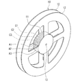
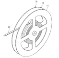
以下、本発明の実施の形態について図面を参照して詳細に説明する。始めに、図1および図2を参照して、本発明の一実施の形態に係る電子部品保持済キャリアテープ巻回体について説明する。図1は、本実施の形態に係る電子部品保持済キャリアテープ巻回体を示す斜視図である。図2は、図1に示した電子部品保持済キャリアテープ巻回体おけるリールを示す斜視図である。 Hereinafter, embodiments of the present invention will be described in detail with reference to the drawings. First, with reference to FIG. 1 and FIG. 2, the electronic component holding | maintenance carrier tape winding body which concerns on one embodiment of this invention is demonstrated. FIG. 1 is a perspective view showing an electronic component-retained carrier tape winding body according to the present embodiment. FIG. 2 is a perspective view showing a reel in the carrier tape wound body with the electronic component held as shown in FIG.
本実施の形態に係る電子部品保持済キャリアテープ巻回体(以下、単に巻回体と記す。)1は、リール10と、複数の電子部品30を保持したキャリアテープ21である電子部品保持済キャリアテープ20とを備えている。図2に示したように、リール10は、円柱形状の芯部11と、この芯部11の中心軸方向の両端に接合された2枚の側板12とを有している。リール10には、芯部11の中心軸の位置に、芯部11および2枚の側板12を貫通するように形成された孔13が形成されている。
An electronic component-retained carrier tape winding body (hereinafter simply referred to as a wound body) 1 according to the present embodiment is a
図1には、キャリアテープ21が、電子部品30を収納するための凹部22が所定のピッチで配列されたエンボスキャリアテープである例を示している。この例では、各凹部22に電子部品30が収納されている。電子部品保持済キャリアテープ20については、後で更に詳しく説明する。
FIG. 1 shows an example in which the
リール10の芯部11は、電子部品保持済キャリアテープ20を複数列に巻くことのできる中心軸方向の長さを有している。電子部品保持済キャリアテープ20は、リール10の芯部11の中心軸方向における位置を変えながらリール10の芯部11の周りに複数列に巻かれている。図1には、芯部11が、電子部品保持済キャリアテープ20を3列に巻くことのできる中心軸方向の長さを有し、電子部品保持済キャリアテープ20が、リール10の芯部11の周りに3列に巻かれている例を示している。しかし、芯部11は、電子部品保持済キャリアテープ20を2列以上巻くことのできる中心軸方向の長さを有し、電子部品保持済キャリアテープ20は、リール10の芯部11の周りに2列以上巻かれていればよい。
The
ここで、図1に示したように電子部品保持済キャリアテープ20がリール10の芯部11の周りに3列に巻かれる場合を例にとって、電子部品保持済キャリアテープ20の巻き方について、具体的に説明する。まず、図2に示したように、芯部11の外周面を中心軸方向に3等分して形成された3つの領域を領域A1,A2,A3とし、領域A1,A2,A3の中心の位置をそれぞれ位置C1,C2,C3とする。領域A2は、領域A1と領域A3の間に位置する。位置C1,C2の間隔と位置C2,C3の間隔は互いに等しい。
Here, taking as an example the case where the electronic component-retained
電子部品保持済キャリアテープ20は、まず、芯部11の外周面上において、例えば領域A1,A2,A3の順に芯部11の中心軸方向における位置を変えながら、つる巻き状に3回巻かれる。これにより、電子部品保持済キャリアテープ20のうち最内周の1層目部分が芯部11の周りに3列に巻かれる。このときの電子部品保持済キャリアテープ20の位置の変化の方向を第1の方向とする。次に、電子部品保持済キャリアテープ20は、1層目部分の上において、第1の方向とは反対の第2の方向に芯部11の中心軸方向における位置を変えながら、つる巻き状に3回巻かれる。これにより、電子部品保持済キャリアテープ20のうちの2層目部分が、1層目部分の周りに3列に巻かれる。以下、1層目部分の形成時の巻き方と、2層目部分の形成時の巻き方が交互に繰り返されて、電子部品保持済キャリアテープ20は、リール10の芯部11の周りに、1層当たり3列で、複数層に巻かれる。
First, the electronic component-retained
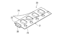
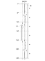
次に、図3ないし図5を参照して、電子部品保持済キャリアテープ20について詳しく説明する。図3は、キャリアテープ21の一部を示す平面図である。図4は、図3における4−4線の位置におけるキャリアテープ21の断面を示す断面図である。図5は、電子部品保持済キャリアテープ20の一部を示す斜視図である。キャリアテープ21は、可撓性を有する帯状体である。図3および図4には、キャリアテープ21がエンボスキャリアテープである例を示している。この例では、キャリアテープ21は、所定のピッチで配列された複数の凹部22と、例えば凹部22のピッチと等しいピッチで配列された複数の送り用の孔23とを有している。図5に示したように、電子部品保持済キャリアテープ20は、キャリアテープ21と、キャリアテープ21の複数の凹部22に収納された複数の電子部品30とを有している。電子部品30は、例えば、表面実装されるチップ部品である。電子部品保持済キャリアテープ20は、更に、複数の凹部22と複数の電子部品30を覆うように、キャリアテープ21に接合されたカバーテープ24を有している。
Next, with reference to FIG. 3 thru | or FIG. 5, the electronic component holding |
ここで、本実施の形態に係る電子部品保持済キャリアテープ巻回体の製造装置(以下、単に、巻回体の製造装置または製造装置と記す。)を含むテーピング装置について説明する。テーピング装置は、部品整列供給装置(パーツフィーダー)と、特性検査装置と、本実施の形態に係る巻回体の製造装置とを含んでいる。部品整列供給装置は、投入された複数の電子部品30を整列させて特性検査装置に供給する。特性検査装置は、部品整列供給装置より供給された複数の電子部品30の特性を順次検査し、良品の電子部品30のみを順次、キャリアテープ21の凹部22に収納する。特性検査装置は、更に、電子部品30が収納された凹部22を順次覆うように、カバーテープ24をキャリアテープ21に接合して、電子部品保持済キャリアテープ20を形成し、これを巻回体の製造装置に供給する。巻回体の製造装置は、特性検査装置より供給された電子部品保持済キャリアテープ20を、リール10の芯部11の周りに巻いて巻回体1を製造する。
Here, a description will be given of a taping apparatus including a manufacturing apparatus for an electronic component-retained carrier tape winding body (hereinafter simply referred to as a winding body manufacturing apparatus or manufacturing apparatus) according to the present embodiment. The taping device includes a parts alignment supply device (part feeder), a characteristic inspection device, and a wound body manufacturing device according to the present embodiment. The component alignment supply device aligns the supplied
次に、図6の流れ図を参照して、上記テーピング装置の動作について説明する。テーピング装置によって処理される複数の電子部品30は、テーピング装置の部品整列供給装置に投入される。テーピング装置では、部品整列供給装置によって複数の電子部品30を整列させて特性検査装置に供給する(ステップS101)。次に、特性検査装置によって、複数の電子部品30の特性を検査し(ステップS102)、良品の電子部品30のみを順次、キャリアテープ21の凹部22に収納し、電子部品30が収納された凹部22を順次覆うようにカバーテープ24をキャリアテープ21に接合して、電子部品保持済キャリアテープ20を形成する(ステップS103)。次に、巻回体の製造装置によって、所定の個数の電子部品30を保持した電子部品保持済キャリアテープ20をリール10に巻き取って、巻回体1を製造する。テーピング装置は、所定の個数の電子部品30を保持した電子部品保持済キャリアテープ20をリール10に巻き終えると、それを知らせるアラームを発生すると共に、動作を終了する。なお、ステップS102、S103、S104は、1つの電子部品30に関しては図6に示したように時系列的に実行されるが、異なる電子部品に対しては同時に実行される。1つの巻回体1の製造が完了すると、作業者は、巻回体1を、電子部品保持済キャリアテープ20が巻かれていないリール10(以下、空のリールと言う。)に交換して、テーピング装置の動作を再開させる。
Next, the operation of the taping device will be described with reference to the flowchart of FIG. The plurality of
次に、巻回体1の完成後に行われる編集作業について説明する。この編集作業は、巻回体1に含まれる1本の電子部品保持済キャリアテープ20を、それぞれ、巻回体1に含まれる電子部品30の個数よりも少ない個数の電子部品30を含む複数の分割テープに分割し、各分割テープを、この分割テープを1列にのみ巻くことのできる中心軸方向の長さを有する芯部を備えたリールの芯部の周りに1列に巻いて、供給用巻回体を作製する作業である。供給用巻回体は、例えば電子部品実装装置において電子部品30の供給源として使用される。
Next, editing work performed after the winding
なお、一般的に、電子部品実装装置において使用される供給用巻回体におけるリールの径は、従来のテーピング装置によって電子部品保持済キャリアテープ20を巻くリールの径よりも小さい。そのため、従来のテーピング装置によって、電子部品保持済キャリアテープ20を、このテープ20を1列にのみ巻くことのできる中心軸方向の長さを有する芯部を備えたリールの芯部の周りに1列に巻いた場合においても、上述の編集作業は行われていた。
In general, the diameter of the reel in the supply winding body used in the electronic component mounting apparatus is smaller than the diameter of the reel on which the electronic component holding
現在、1本の電子部品保持済キャリアテープ20が複数列に巻かれた本実施の形態に係る巻回体1を電子部品30の供給源として使用できる電子部品実装装置は存在しない。しかし、本実施の形態に係る巻回体1を使用できる電子部品実装装置が実現すれば、上記供給用巻回体を作製することなく、巻回体1を電子部品実装装置に供給することも可能になる。
Currently, there is no electronic component mounting apparatus that can use the
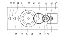
次に、本実施の形態に係る巻回体の製造装置について説明する。図7は、本実施の形態に係る巻回体の製造装置、リールおよび電子部品保持済キャリアテープを示す平面図である。図8は、図7に示した製造装置、リールおよび電子部品保持済キャリアテープを示す側面図である。図9は、図7に示した製造装置における主要部を示す側面図である。本実施の形態に係る巻回体の製造装置40は、ハウジング41と、リール駆動装置50と、案内部材42と、変位機構60とを備えている。リール駆動装置50と変位機構60は、ハウジング41に取り付けられている。巻回体の製造装置40は、更に、ハウジング41に対して、回転可能に取り付けられたローラ90を備えている。なお、ローラ90は、図8にのみ示している。
Next, the manufacturing apparatus of the wound body which concerns on this Embodiment is demonstrated. FIG. 7 is a plan view showing the wound body manufacturing apparatus, the reel, and the carrier tape with electronic components held therein according to the present embodiment. FIG. 8 is a side view showing the manufacturing apparatus, the reel, and the carrier tape holding electronic components shown in FIG. FIG. 9 is a side view showing the main part of the manufacturing apparatus shown in FIG. The wound
リール駆動装置50は、リール10が装着される回転軸51と、回転軸51を回転させるモータ52とを有している。リール10は、図2に示した孔13に回転軸51が挿入され、且つ孔13と回転軸51の位置関係が固定されることによって、回転軸51に装着される。リール駆動装置50は、モータ52によって回転軸51を回転させることによって、リール10を、芯部11の中心軸を中心として回転させる。図7において、回転軸51に装着された状態におけるリール10の芯部11の中心軸方向、すなわち回転軸51の中心軸方向を、記号Cを付した矢印で表す。
The
案内部材42は、電子部品保持済キャリアテープ20のうちリール10の芯部11の周りに巻かれる前の部分をリール10に案内するローラである。案内部材42は、電子部品保持済キャリアテープ20が接する円柱部42aと、この円柱部42aの軸方向の両側に設けられた2つのフランジ部42bとを有している。また、案内部材42は、回転軸51に装着された状態におけるリール10の2枚の側板12の外周の近傍に配置されている。図7および図8に示したように、電子部品保持済キャリアテープ20のうちリール10の芯部11の周りに巻かれる前の部分は、円柱部42aの外周面に接し且つ2つのフランジ部42bに挟まれて、その位置が規制されて、リール10に案内される。
The
変位機構60は、電子部品保持済キャリアテープ20が、リール10の芯部11の中心軸方向Cにおける位置を変えながらリール10の芯部11の周りに複数列に巻かれるように、リール10が回転しているときにリール10と案内部材42との位置関係を変化させる。本実施の形態では、特に、変位機構60は、モータ52によって駆動されて、案内部材42を、リール10の回転に同期して周期的に芯部11の中心軸方向Cに往復運動させる。
The
以下、変位機構60について詳しく説明する。変位機構60は、ハウジング41に対して回転可能に取り付けられた軸61,62,63と、ハウジング41に対して固定された軸64と、回転軸51の中心軸方向Cに進退可能にハウジング41に取り付けられた軸65とを有している。案内部材42は、軸65に対して回転可能に取り付けられている。
Hereinafter, the
変位機構60は、更に、回転軸51に固定された歯車71と、軸61に固定された歯車72,73と、軸62に固定された歯車74と、軸63に固定された歯車75とを備えている。歯車72は、歯車71に噛み合っている。歯車74は、歯車73と歯車75に噛み合っている。
The
変位機構60は、更に、カム80を有している。カム80は、原動節81と従動節82を備えている。原動節81は、周囲に溝83が形成された円柱形状を有し、軸63に固定されている。従動節82は、移動体84と、この移動体84に固定されたピン85とを有している。ピン85は、原動節81の溝83に挿入されている。移動体84は、軸64に対して回転軸51の中心軸方向Cに進退可能に取り付けられていると共に、軸65に固定されている。
The
歯車72の歯数は、歯車71の歯数の2倍である。例えば、歯車71の歯数は20であり、歯車72の歯数は40である。歯車74の歯数は、歯車73の歯数の3倍である。例えば、歯車74の歯数は60であり、歯車73の歯数は20である。歯車75の歯数は、歯車74の歯数と等しく、例えば60である。
The number of teeth of the
このような構成の変位機構60では、回転軸51が回転すると、それに連動してカム80の原動節81が回転する。原動節81の回転数は、回転軸51の回転数の1/6である。原動節81が回転すると、従動節82のピン85が原動節81の溝83に従って変位することによって、従動節82が回転軸51の中心軸方向Cに往復運動し、それに伴い、軸65および案内部材42が回転軸51の中心軸方向Cに往復運動する。このようにして、変位機構60は、モータ52によって駆動されて、案内部材42を、リール10の回転に同期して周期的に芯部11の中心軸方向Cに往復運動させる。案内部材42の往復運動の周期は、リール10の回転の周期の1/6である。
In the
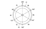
次に、図10ないし図12を参照して、カム80の原動節81について詳しく説明する。図10は、カム80の原動節81を示す平面図である。図11は、図10に示した原動節81の側面図である。図12は、図10に示した原動節81における溝83を展開して示す展開図である。図11および図12に示したように、溝83は、原動節81の円周方向に6等分して形成された6つの領域R1,R2,R3,R4,R5,R6を有している。ここで、図9と同じ方向から原動節81を見たときに、図11に示したように、基準位置から反時計回り方向に進むときに値が大きくなるように角度を表す。領域R1,R2,R3,R4,R5,R6は、それぞれ、0°〜60°、60°〜120°、120°〜180°、180°〜240°、240°〜300°、300°〜360°の範囲の領域である。
Next, the driving
また、原動節81の中心軸に垂直な3つの基準面P1,P2,P3を以下のように定義する。基準面P2は、基準面P1と基準面P3の間に位置する。基準面P1,P2の間隔と基準面P2,P3の間隔は、互いに等しく、且つ図2に示した位置C1,C2の間隔および位置C2,C3の間隔と等しい。図12に示したように、領域R1では、溝83の中心は基準面P1上に位置する。領域R2では、溝83の中心は、60°から約80°の範囲において基準面P1上の位置から基準面P2上の位置へ徐々に移動し、領域R2の残り範囲において基準面P2上に位置する。領域R3では、溝83の中心は、120°から約140°の範囲において基準面P2上の位置から基準面P3上の位置へ徐々に移動し、領域R3の残り範囲において基準面P3上に位置する。領域R4では、溝83の中心は基準面P3上に位置する。領域R5では、溝83の中心は、240°から約260°の範囲において基準面P3上の位置から基準面P2上の位置へ徐々に移動し、領域R5の残り範囲において基準面P2上に位置する。領域R6では、溝83の中心は、300°から約320°の範囲において基準面P2上の位置から基準面P1上の位置へ徐々に移動し、領域R6の残り範囲において基準面P1上に位置する。
Further, three reference planes P1, P2, P3 perpendicular to the central axis of the driving
従動節82のピン85は、原動節81の回転に伴って、ピン85の中心が溝83の中心に従って移動するように往復運動する。ピン85の中心が基準面P1上に位置するとき、案内部材42は、電子部品保持済キャリアテープ20のうちリール10の芯部11の周りに巻かれる前の部分を、芯部11の外周面のうちの領域A1の周りに案内する位置にある。ピン85の中心が基準面P2上に位置するとき、案内部材42は、電子部品保持済キャリアテープ20のうちリール10の芯部11の周りに巻かれる前の部分を、芯部11の外周面のうちの領域A2の周りに案内する位置にある。ピン85の中心が基準面P3上に位置するとき、案内部材42は、電子部品保持済キャリアテープ20のうちリール10の芯部11の周りに巻かれる前の部分を、芯部11の外周面のうちの領域A3の周りに案内する位置にある。
The
次に、本実施の形態に係る巻回体の製造装置40の動作および本実施の形態に係る巻回体の製造方法について説明する。巻回体の製造装置40において、モータ52が回転すると、回転軸51およびリール10が回転すると共に、モータ52によって変位機構60が駆動されて、案内部材42はリール10の回転に同期して周期的に芯部11の中心軸方向Cに往復運動する。案内部材42の往復運動の周期は、リール10の回転の周期の1/6である。
Next, an operation of the wound
巻回体の製造装置40の動作開始前においては、案内部材42は、例えば、電子部品保持済キャリアテープ20のうちリール10の芯部11の周りに巻かれる前の部分を、芯部11の外周面のうちの領域A1に案内する位置に設定される。また、特性検査装置によって形成された電子部品保持済キャリアテープ20の端は、作業者によって、例えばリール10の芯部11の外周面上の領域A1に位置するように、芯部11に固定される。その後、巻回体の製造装置40が動作を開始することによって、電子部品保持済キャリアテープ20は、リール10の芯部11の周りに巻かれる。このとき、案内部材42は、特性検査装置によって形成された電子部品保持済キャリアテープ20のうちリール10の芯部11の周りに巻かれる前の部分をリール10に案内する。案内部材42は、前述のように、リール10の回転の周期の1/6で、芯部11の中心軸方向Cに往復運動する。
Prior to the start of the operation of the wound
従動節82のピン85の中心が基準面P1上に位置するとき、案内部材42は、電子部品保持済キャリアテープ20のうちリール10の芯部11の周りに巻かれる前の部分を、芯部11の外周面のうちの領域A1の周りに案内する。ピン85の中心が基準面P2上に位置するとき、案内部材42は、電子部品保持済キャリアテープ20のうちリール10の芯部11の周りに巻かれる前の部分を、芯部11の外周面のうちの領域A2の周りに案内する。ピン85の中心が基準面P3上に位置するとき、案内部材42は、電子部品保持済キャリアテープ20のうちリール10の芯部11の周りに巻かれる前の部分を、芯部11の外周面のうちの領域A3の周りに案内する。
When the center of the
上述の案内部材42の作用により、電子部品保持済キャリアテープ20は、まず、リール10の芯部11の外周面上において、領域A1,A2,A3の順に芯部11の中心軸方向における位置を第1の方向に変えながら、つる巻き状に3回巻かれる。これにより、電子部品保持済キャリアテープ20のうち最内周の1層目部分が芯部11の周りに3列に巻かれる。次に、電子部品保持済キャリアテープ20は、1層目部分の上において、第1の方向とは反対の第2の方向に芯部11の中心軸方向における位置を変えながら、つる巻き状に3回巻かれる。これにより、電子部品保持済キャリアテープ20のうちの2層目部分が1層目部分の周りに3列に巻かれる。以下、1層目部分の形成時の巻き方と、2層目部分の形成時の巻き方が交互に繰り返されて、電子部品保持済キャリアテープ20は、リール10の芯部11の周りに、1層当たり3列で、複数層に巻かれる。
By the action of the
図13は、図7および図8におけるリール10と電子部品保持済キャリアテープ20を示す斜視図である。図13は、巻回体1が完成する前の状態を表している。所定の個数の電子部品30を保持した電子部品保持済キャリアテープ20をリール10に巻き終えると、図1に示した巻回体1が完成する。
FIG. 13 is a perspective view showing the
本実施の形態に係る巻回体1の製造方法は、本実施の形態に係る巻回体の製造装置40によって実行される。この巻回体1の製造方法では、リール10を、芯部11の中心軸を中心として回転させ、リール10が回転しているときに、電子部品保持済キャリアテープ20のうちリール10の芯部11の周りに巻かれる前の部分とリール10との位置関係を変化させて、電子部品保持済キャリアテープ20を、リール10の芯部11の中心軸方向における位置を変えながらリール10の芯部11の周りに複数列に巻く。
The manufacturing method of the
なお、本実施の形態に係る巻回体の製造装置40は、図8に示したローラ90を備えている。このローラ90は、案内部材42と異なり、往復運動は行わない。巻回体の製造装置40では、リール10の代りに、電子部品保持済キャリアテープ20を1列にのみ巻くことのできる中心軸方向の長さを有する芯部を備えたリール(以下、1列用リールと言う。)を回転軸51に装着し、電子部品保持済キャリアテープ20を、案内部材42ではなくローラ90によって1列用リールに案内することにより、電子部品保持済キャリアテープ20を1列用リールの芯部の周りに1列に巻くこともできるようになっている。
In addition, the
次に、本実施の形態に係る巻回体の製造装置40および巻回体の製造方法、ならびに巻回体1の効果について説明する。本実施の形態によれば、電子部品保持済キャリアテープ20が、リール10の芯部11の中心軸方向における位置を変えながらリール10の芯部11の周りに複数列に巻かれてなる巻回体1が得られる。ここで、本実施の形態において、リール10の芯部11の周りに巻かれる電子部品保持済キャリアテープ20の列の数をN(Nは2以上の整数)とする。
Next, the
また、電子部品保持済キャリアテープ20を1列用リールの芯部の周りに1列に巻く場合を比較例とし、この比較例によって製造された巻回体を、比較例の巻回体とする。なお、比較例における1列用リールの径は、本実施の形態におけるリール10の径と等しいものとする。
Moreover, the case where the electronic component holding
本実施の形態によれば、比較例の巻回体における1本の電子部品保持済キャリアテープ20に比べて多くの(具体的にはN倍の個数の)電子部品30を保持した1本の電子部品保持済キャリアテープ20を備えた巻回体1を製造することができる。そのため、本実施の形態によれば、電子部品保持済キャリアテープ20を巻き終えたリールを空のリールに交換するリール交換作業を挟んで、電子部品保持済キャリアテープ20をリールに巻き取る処理が繰り返し行われる場合において、比較例に比べて、リール交換作業が発生する時間間隔が約N倍に長くなる。これにより、本実施の形態によれば、所定の時間内に占めるリール交換作業の時間を短縮することが可能になる。
According to the present embodiment, one
また、本実施の形態によれば、1回の編集作業において、比較例に比べて、N倍の数の供給用巻回体を作製することができる。そのため、本実施の形態によれば、編集作業を効率的に行うことができる。 Moreover, according to this Embodiment, the winding body for supply of N times can be produced in one editing operation compared with a comparative example. Therefore, according to the present embodiment, editing work can be performed efficiently.
なお、現在、テーピング装置における、電子部品を保持する前のキャリアテープの供給源として、電子部品を保持する前のキャリアテープがリールの芯部の周りに複数列に巻かれたものは存在する。しかし、現在、本実施の形態に係る巻回体1のように、電子部品保持済キャリアテープ20が、リール10の芯部11の中心軸方向における位置を変えながらリール10の芯部11の周りに複数列に巻かれたものは存在していない。また、現在、電子部品実装装置では、電子部品の供給源として、電子部品保持済キャリアテープ20がリールの芯部の周りに1列に巻かれたものが使用されている。また、これまで、電子部品実装装置における電子部品の供給源として、本実施の形態に係る巻回体1のように、電子部品保持済キャリアテープ20が、リール10の芯部11の中心軸方向における位置を変えながらリール10の芯部11の周りに複数列に巻かれたものを必要とするような課題は認識されていない。
Currently, as a supply source of a carrier tape before holding an electronic component in a taping device, there is a carrier tape before holding an electronic component wound around a core portion of a reel in a plurality of rows. However, at present, like the
以下、具体的な例を用いて、本実施の形態による効果について更に説明する。ここでは、テーピング装置の特性検査装置によって、1分間にキャリアテープ21の凹部22に収納される電子部品30の個数の平均値を180個とする。また、比較例では、10,000個の電子部品30を保持した電子部品保持済キャリアテープ20を、1列用リールの芯部の周りに1列に巻いて、比較例の巻回体を製造するものとする。また、本実施の形態における実施例では、30,000個の電子部品保持済キャリアテープ20を、リール10の芯部11の中心軸方向における位置を変えながらリール10の芯部11の周りに3列に巻いて、巻回体1を製造するものとする。比較例と実施例のいずれにおいても、テーピング装置の平均稼働台数は18台とし、1回のリール交換作業の時間を2.12分とする。また、比較例と実施例のいずれにおいても、編集作業では、2,000個の電子部品30を含む分割テープがリールの芯部の周りに1列に巻かれた供給用巻回体を作製するものとする。
Hereinafter, the effect by this Embodiment is further demonstrated using a specific example. Here, the average value of the number of
比較例では、1台のテーピング装置においてリール交換作業が発生する時間間隔は、10,000(個)÷180(個/分)+2.12(分)、すなわち約57.7分となり、18台のテーピング装置が稼働しているときのリール交換作業が発生する時間間隔は、約3.20分となる。比較例では、作業者が1人の場合には、約3.20分おきにリール交換作業が発生し、リール交換作業に2.12分掛かることから、作業者がリール交換作業以外の作業に利用可能な時間は約1.08分しかない。比較例において、作業者が2人で、1人が9台のテーピング装置に関する作業を行う場合でも、1人の作業者につき、約6.40分おきにリール交換作業が発生し、リール交換作業に2.12分掛かることから、1人の作業者がリール交換作業以外の作業に利用可能な時間は約4.28分しかない。いずれの場合においても、作業者がリール交換作業以外の作業に利用可能な時間は非常に短く、実際には、その時間内でリール交換作業以外の作業を行うことができない場合が発生し得る。 In the comparative example, the time interval at which the reel replacement work occurs in one taping device is 10,000 (pieces) / 180 (pieces / minute) +2.12 (minutes), that is, about 57.7 minutes. The time interval at which the reel replacement work occurs when the taping device is operating is about 3.20 minutes. In the comparative example, when there is one worker, reel replacement work occurs every 3.20 minutes, and the reel replacement work takes 2.12 minutes. The available time is only about 1.08 minutes. In the comparative example, even if there are two workers and one person performs work on nine taping devices, reel replacement work occurs every 6.40 minutes for each worker. Since it takes 2.12 minutes, one worker can use only about 4.28 minutes for work other than reel replacement work. In any case, the time that an operator can use for work other than the reel replacement work is very short, and in fact, it may occur that the work other than the reel replacement work cannot be performed within that time.
実施例では、1台のテーピング装置においてリール交換作業が発生する時間間隔は、30,000(個)÷180(個/分)+2.12(分)、すなわち約168.8分となり、18台のテーピング装置が稼働しているときのリール交換作業が発生する時間間隔は、約9.38分となる。実施例では、作業者が1人の場合には、約9.38分おきにリール交換作業が発生し、リール交換作業に2.12分掛かることから、作業者がリール交換作業以外の作業に利用可能な時間は約7.26分となる。実施例において、作業者が2人で、1人が9台のテーピング装置に関する作業を行う場合には、1人の作業者につき、約18.76分おきにリール交換作業が発生し、リール交換作業に2.12分掛かることから、1人の作業者がリール交換作業以外の作業に利用可能な時間は約16.6分となる。いずれの場合においても、比較例に比べて、作業者がリール交換作業以外の作業に利用可能な時間は大幅に増加し、その時間内でリール交換作業以外の作業を行うことが十分に可能になる。 In the embodiment, the time interval at which the reel replacement work occurs in one taping device is 30,000 (pieces) / 180 (pieces / minute) +2.12 (minutes), that is, about 168.8 minutes, 18 units. The time interval at which the reel replacement work occurs when the taping apparatus is operating is about 9.38 minutes. In the embodiment, when there is one worker, the reel replacement work occurs every 9.38 minutes, and the reel replacement work takes 2.12 minutes. The available time will be about 7.26 minutes. In the embodiment, when two workers are involved and one person performs work related to nine taping devices, reel replacement work occurs every 18.76 minutes for each worker. Since the work takes 2.12 minutes, the time that one worker can use for work other than the reel replacement work is about 16.6 minutes. In any case, compared to the comparative example, the time available for the operator to perform work other than the reel replacement work is greatly increased, and it is possible to perform work other than the reel replacement work within that time. Become.
次に、比較例と実施例とで、所定の時間内に占めるリール交換作業の時間について比較する。ここでは、720分の間、2人の作業者によって18台のテーピング装置に関する作業を行うものとする。この場合、比較例では、1人の作業者につき、約6.40分おきにリール交換作業が発生することから、720分の間に発生するリール交換作業の回数は、約112.5回となる。一方、実施例では、1人の作業者につき、約18.76分おきにリール交換作業が発生することから、720分の間に発生するリール交換作業の回数は、約38.4回となる。従って、実施例では、比較例に比べて、1人の作業者につき、720分の間に発生するリール交換作業の回数を約74.1回少なくすることができる。また、実施例では、比較例に比べて、1人の作業者につき、720分の間に占めるリール交換作業の時間を、約157.1分短縮することができる。 Next, in the comparative example and the embodiment, the time for the reel replacement work that occupies within a predetermined time is compared. Here, it is assumed that work for 18 taping devices is performed by two workers for 720 minutes. In this case, in the comparative example, the reel replacement work is generated every 6.40 minutes per worker, and therefore the number of reel replacement work generated during 720 minutes is about 112.5 times. Become. On the other hand, in the embodiment, since the reel exchange work is performed every 18.76 minutes per worker, the number of reel exchange work that occurs during 720 minutes is about 38.4 times. . Therefore, in the embodiment, compared with the comparative example, the number of reel replacement operations that occur in 720 minutes per worker can be reduced by about 74.1 times. Further, in the embodiment, the time required for the reel replacement work for one worker for 720 minutes can be shortened by about 157.1 minutes as compared with the comparative example.
また、実施例によれば、比較例に比べて、リール交換作業の時間の短縮分だけ、テーピング装置の稼働時間を長くすることができる。従って、実施例によれば、比較例に比べて、1人の作業者につき、720分当たり、157.1(分)×180(個/分)、すなわち28,278個だけ多くの電子部品30を生産することが可能になる。また、実施例によれば、比較例に比べて、1人の作業者につき、1日当たり56,556個、1月(30日)当たり1,696,680個だけ多くの電子部品30を生産することが可能になる。
Further, according to the embodiment, it is possible to lengthen the operation time of the taping apparatus by the amount corresponding to the shortening of the reel replacement work time as compared with the comparative example. Therefore, according to the embodiment, as compared with the comparative example, the number of
また、作業者の1分当たりの労務費をLRとすると、実施例によれば、比較例に比べて、1人の作業者につき、720分当たり157.1×LR、1日当たり157.1×LR×2、1月(30日)当たり157.1×LR×2×30だけ、労務費を低減することが可能になる。 Further, assuming that the labor cost per minute of the worker is LR, according to the embodiment, 157.1 × LR per 720 minutes per worker, 157.1 × per day, as compared with the comparative example. Labor costs can be reduced by LR × 2 and 157.1 × LR × 2 × 30 per month (30 days).
また、比較例では1回の編集作業において5巻の供給用巻回体が作製されるのに対し、実施例では1回の編集作業において15巻の供給用巻回体が作製される。このように、実施例によれば、比較例に比べて、1回の編集作業において、3倍の数の供給用巻回体を作製することができる。そのため、実施例によれば、比較例に比べて、編集作業を効率的に行うことができる。 Further, in the comparative example, five supply winding bodies are produced in one editing operation, whereas in the embodiment, 15 supply winding bodies are produced in one editing operation. As described above, according to the embodiment, it is possible to produce three times as many winding bodies for supply in one editing operation as compared with the comparative example. Therefore, according to the embodiment, editing can be performed more efficiently than in the comparative example.
なお、本発明は、上記実施の形態に限定されず、種々の変更が可能である。例えば、実施の形態では、変位機構60は、案内部材42を移動させてリール10と案内部材42との位置関係を変化させている。しかし、本発明における変位機構は、リール10と案内部材42との位置関係を変化させるために、リール10を移動させてもよいし、リール10と案内部材42の両方を移動させてもよい。
In addition, this invention is not limited to the said embodiment, A various change is possible. For example, in the embodiment, the
1…電子部品保持済キャリアテープ巻回体、10…リール、11…芯部、12…側板、20…電子部品保持済キャリアテープ、21…キャリアテープ、22…凹部、24…カバーテープ、30…電子部品、40…巻回体の製造装置、42…案内部材、50…リール駆動装置、51…回転軸、52…モータ、60…変位機構、61〜65…軸、71〜75…歯車、80…カム、81…原動節、82…従動節、83…溝、84…移動体、85…ピン。
DESCRIPTION OF
Claims (3)
前記リールを、前記芯部の中心軸を中心として回転させるリール駆動装置と、
前記電子部品保持済キャリアテープのうち前記リールの芯部の周りに巻かれる前の部分を前記リールに案内する案内部材と、
前記電子部品保持済キャリアテープが、前記リールの芯部の中心軸方向における位置を変えながら前記リールの芯部の周りに複数列且つ複数層に巻かれるように、前記リールが回転しているときに前記リールと前記案内部材との位置関係を変化させる変位機構とを備え、
前記変位機構は、前記案内部材を、前記リールの回転に同期して周期的に前記芯部の中心軸方向に往復運動させることを特徴とする電子部品保持済キャリアテープ巻回体の製造装置。 A carrier tape having a plurality of recesses arranged at a predetermined pitch, a plurality of electronic components housed in the plurality of recesses, and joined to the carrier tape so as to cover the plurality of recesses and the plurality of electronic components A carrier tape having a cover tape and an electronic component held carrier tape is wound around the core portion of the reel having a core portion having a length in a central axis direction capable of winding the electronic component held carrier tape in a plurality of rows. A manufacturing apparatus for manufacturing a wound carrier tape wound electronic component,
A reel driving device for rotating the reel around a central axis of the core;
A guide member that guides the reel before a portion around the core of the reel of the carrier tape having the electronic component held thereon;
When the reel rotates so that the electronic component-retained carrier tape is wound in a plurality of rows and a plurality of layers around the reel core while changing the position of the reel core in the central axis direction And a displacement mechanism that changes a positional relationship between the reel and the guide member,
The displacement mechanism causes the guide member to reciprocate periodically in the direction of the central axis of the core portion in synchronization with the rotation of the reel.
前記変位機構は、前記モータによって駆動されて前記案内部材を往復運動させることを特徴とする請求項1記載の電子部品保持済キャリアテープ巻回体の製造装置。 The reel driving device has a rotating shaft on which the reel is mounted, and a motor that rotates the rotating shaft,
The displacement mechanism, apparatus for manufacturing electronic parts holding spent carrier tape winding body according to claim 1, wherein the reciprocating said guide member being driven by said motor.
前記リールを、前記芯部の中心軸を中心として回転させ、
前記リールが回転しているときに、前記電子部品保持済キャリアテープのうち前記リールの芯部の周りに巻かれる前の部分と前記リールとの位置関係を変化させて、前記電子部品保持済キャリアテープを、前記リールの芯部の中心軸方向における位置を変えながら前記リールの芯部の周りに複数列且つ複数層に巻く
ことを特徴とする電子部品保持済キャリアテープ巻回体の製造方法。
A carrier tape having a plurality of recesses arranged at a predetermined pitch, a plurality of electronic components housed in the plurality of recesses, and joined to the carrier tape so as to cover the plurality of recesses and the plurality of electronic components A carrier tape having a cover tape and an electronic component held carrier tape is wound around the core portion of the reel having a core portion having a length in a central axis direction capable of winding the electronic component held carrier tape in a plurality of rows. A method for producing a wound carrier tape wound electronic component,
Rotate the reel around the central axis of the core,
When the reel is rotating, the electronic component-retained carrier tape is changed by changing the positional relationship between the reel and the portion of the electronic component-retained carrier tape before being wound around the core of the reel. A method of manufacturing an electronic component-retained carrier tape winding body, wherein a tape is wound in a plurality of rows and a plurality of layers around a core portion of the reel while changing the position of the core portion of the reel in the central axis direction.
Priority Applications (1)
| Application Number | Priority Date | Filing Date | Title |
|---|---|---|---|
| JP2009256652A JP5141663B2 (en) | 2009-11-10 | 2009-11-10 | Apparatus and method for manufacturing carrier tape wound body with electronic components held |
Applications Claiming Priority (1)
| Application Number | Priority Date | Filing Date | Title |
|---|---|---|---|
| JP2009256652A JP5141663B2 (en) | 2009-11-10 | 2009-11-10 | Apparatus and method for manufacturing carrier tape wound body with electronic components held |
Publications (2)
| Publication Number | Publication Date |
|---|---|
| JP2011102155A JP2011102155A (en) | 2011-05-26 |
| JP5141663B2 true JP5141663B2 (en) | 2013-02-13 |
Family
ID=44192689
Family Applications (1)
| Application Number | Title | Priority Date | Filing Date |
|---|---|---|---|
| JP2009256652A Active JP5141663B2 (en) | 2009-11-10 | 2009-11-10 | Apparatus and method for manufacturing carrier tape wound body with electronic components held |
Country Status (1)
| Country | Link |
|---|---|
| JP (1) | JP5141663B2 (en) |
Family Cites Families (5)
| Publication number | Priority date | Publication date | Assignee | Title |
|---|---|---|---|---|
| US4349162A (en) * | 1981-01-05 | 1982-09-14 | Western Electric Company, Inc. | Device for receiving and packaging a strip of electrical components |
| US4600161A (en) * | 1984-01-04 | 1986-07-15 | Texas Instruments Incorporated | Method and apparatus for storing electrical contact strips |
| JPS60218248A (en) * | 1984-04-13 | 1985-10-31 | Teraoka Seisakusho:Kk | Adhesive tape winding method |
| JP2000226068A (en) * | 1999-02-05 | 2000-08-15 | Matsushita Electronics Industry Corp | Carrier tape and its storing method |
| JP3157008U (en) * | 2009-11-10 | 2010-01-28 | Tdk株式会社 | Carrier tape roll with electronic components |
-
2009
- 2009-11-10 JP JP2009256652A patent/JP5141663B2/en active Active
Also Published As
| Publication number | Publication date |
|---|---|
| JP2011102155A (en) | 2011-05-26 |
Similar Documents
| Publication | Publication Date | Title |
|---|---|---|
| US9082547B2 (en) | Automatic winding machine, air core coil, and winding method of the same | |
| JP3157008U (en) | Carrier tape roll with electronic components | |
| JP5716289B2 (en) | Manufacturing method of stator of rotating electric machine and stator of rotating electric machine | |
| JP2015033146A (en) | Coil mounting method and coil mounting jig | |
| JP2012151996A (en) | Method for annularly arranging coil segment, device for annularly arranging coil segment and stator | |
| JP2014183252A (en) | Coil winding jig and coil winding device employing the same | |
| JP5141663B2 (en) | Apparatus and method for manufacturing carrier tape wound body with electronic components held | |
| JP2013004873A (en) | Edge-wise coil winding device and winding method | |
| JP5687391B2 (en) | Winding device, winding method, and armature manufacturing method | |
| CN107636942A (en) | Coil unit collating unit | |
| JP2009033887A (en) | Winding device | |
| JP6024424B2 (en) | Rectangular wire winding apparatus and winding method | |
| JP5768305B1 (en) | Stator manufacturing method and apparatus | |
| US11171549B2 (en) | Method for forming coil and method for manufacturing stator | |
| JP2007165757A (en) | Dual winding coil, or two-sided coil winding device and winding method | |
| JP2012213817A (en) | Method for assembling shaft and cam lobe, and device therefor | |
| JP5112709B2 (en) | Coil winding apparatus and method | |
| JP4764276B2 (en) | Coil winding method and apparatus | |
| JP3585438B2 (en) | Winding device and winding method | |
| CN102859848B (en) | Stator and manufacturing method thereof | |
| JP2024056509A (en) | Winding shaping device and winding shaping method | |
| JP2007020372A5 (en) | ||
| CN104379273B (en) | Devices for taking-up | |
| CN108702072B (en) | Stator and wire winding method | |
| JP2004336961A (en) | Wave-wound coil, its manufacturing method and its manufacturing apparatus |
Legal Events
| Date | Code | Title | Description |
|---|---|---|---|
| A977 | Report on retrieval |
Free format text: JAPANESE INTERMEDIATE CODE: A971007 Effective date: 20120330 |
|
| A131 | Notification of reasons for refusal |
Free format text: JAPANESE INTERMEDIATE CODE: A131 Effective date: 20120404 |
|
| A521 | Request for written amendment filed |
Free format text: JAPANESE INTERMEDIATE CODE: A523 Effective date: 20120528 |
|
| A131 | Notification of reasons for refusal |
Free format text: JAPANESE INTERMEDIATE CODE: A131 Effective date: 20120801 |
|
| A521 | Request for written amendment filed |
Free format text: JAPANESE INTERMEDIATE CODE: A523 Effective date: 20120925 |
|
| TRDD | Decision of grant or rejection written | ||
| A01 | Written decision to grant a patent or to grant a registration (utility model) |
Free format text: JAPANESE INTERMEDIATE CODE: A01 Effective date: 20121023 |
|
| A01 | Written decision to grant a patent or to grant a registration (utility model) |
Free format text: JAPANESE INTERMEDIATE CODE: A01 |
|
| A61 | First payment of annual fees (during grant procedure) |
Free format text: JAPANESE INTERMEDIATE CODE: A61 Effective date: 20121105 |
|
| FPAY | Renewal fee payment (event date is renewal date of database) |
Free format text: PAYMENT UNTIL: 20151130 Year of fee payment: 3 |
|
| R150 | Certificate of patent or registration of utility model |
Ref document number: 5141663 Country of ref document: JP Free format text: JAPANESE INTERMEDIATE CODE: R150 Free format text: JAPANESE INTERMEDIATE CODE: R150 |
|
| R250 | Receipt of annual fees |
Free format text: JAPANESE INTERMEDIATE CODE: R250 |
|
| R250 | Receipt of annual fees |
Free format text: JAPANESE INTERMEDIATE CODE: R250 |