JP5140389B2 - Stator for rotating electric machine and rotating electric machine using the same - Google Patents
Stator for rotating electric machine and rotating electric machine using the same Download PDFInfo
- Publication number
- JP5140389B2 JP5140389B2 JP2007302780A JP2007302780A JP5140389B2 JP 5140389 B2 JP5140389 B2 JP 5140389B2 JP 2007302780 A JP2007302780 A JP 2007302780A JP 2007302780 A JP2007302780 A JP 2007302780A JP 5140389 B2 JP5140389 B2 JP 5140389B2
- Authority
- JP
- Japan
- Prior art keywords
- stator
- conductor
- coil
- rotating electrical
- electrical machine
- Prior art date
- Legal status (The legal status is an assumption and is not a legal conclusion. Google has not performed a legal analysis and makes no representation as to the accuracy of the status listed.)
- Expired - Fee Related
Links
Images


Classifications
-
- H—ELECTRICITY
- H02—GENERATION; CONVERSION OR DISTRIBUTION OF ELECTRIC POWER
- H02K—DYNAMO-ELECTRIC MACHINES
- H02K3/00—Details of windings
- H02K3/46—Fastening of windings on the stator or rotor structure
- H02K3/52—Fastening salient pole windings or connections thereto
- H02K3/521—Fastening salient pole windings or connections thereto applicable to stators only
- H02K3/522—Fastening salient pole windings or connections thereto applicable to stators only for generally annular cores with salient poles
-
- H—ELECTRICITY
- H02—GENERATION; CONVERSION OR DISTRIBUTION OF ELECTRIC POWER
- H02K—DYNAMO-ELECTRIC MACHINES
- H02K1/00—Details of the magnetic circuit
- H02K1/06—Details of the magnetic circuit characterised by the shape, form or construction
- H02K1/12—Stationary parts of the magnetic circuit
- H02K1/14—Stator cores with salient poles
- H02K1/146—Stator cores with salient poles consisting of a generally annular yoke with salient poles
- H02K1/148—Sectional cores
Description
本発明は、コイル端末を導体に接続した固定子、及びこれを用いた回転電機に関する。 The present invention relates to a stator in which a coil end is connected to a conductor, and a rotating electric machine using the stator.
固定子巻線の形態には、磁極歯毎に素線を集中して巻回してコイルを形成する集中巻と、複数のスロットを跨いで素線を巻回し、コイルエンドで異相、又は同相のコイル同士が重なり合う分布巻とがある。集中巻は、分布巻に比較してコイルエンドを小さくでき、回転電機の小型化、高効率化に有効である。一方、分布巻は、固定子内周の回転磁界分布を正弦波に近づけることができ、集中巻よりも高出力で騒音を小さくすることができる。また、両者に共通して回転電機の高出力化を達成する手段として、コイルの素線銅線に矩形断面の線を使用することにより、固定子スロット内のコイル占積率を高め、電流密度を高める方法がある。
本発明は、固定子のコイル端末を,導体を介して結線した構造を有する回転電機を対象とする。
There are two types of stator windings: concentrated winding that forms a coil by concentrating and winding the wires for each magnetic pole tooth, winding the strands across multiple slots, and having different phases or in-phase at the coil ends. There are distributed windings in which coils overlap. Concentrated winding can make a coil end smaller than distributed winding, and is effective in reducing the size and efficiency of a rotating electrical machine. On the other hand, the distributed winding can bring the rotating magnetic field distribution on the inner circumference of the stator closer to a sine wave, and can reduce the noise with higher output than the concentrated winding. In addition, as a means of achieving high output of the rotating electrical machine in common with both, the coil space factor in the stator slot is increased by using a rectangular cross-section wire for the coil wire copper wire, and the current density There is a way to increase.
The present invention is directed to a rotating electrical machine having a structure in which a coil terminal of a stator is connected via a conductor.
特許文献1には、集中巻のコイル端末をプリント基板や複数の銅板で構成された結線板の接続孔に挿通し、この接続孔の位置に対応させた軸方向に延びるコイル溝を設け、このコイル溝の周壁を溶融してコイル端末を結線板の接続孔に接続する技術が開示されている。
特許文献2ではコイル端末を、樹脂モールドされたバスバー(導体)の孔に挿通し、筒体、接続子といった別部品を介して、コイル端末とバスバー(導体)とを接続した構造になっている。また、特許文献2の技術は、U,V,W相の順に繰り返して周方向に配列しており、コイル両端の軸方向長さは等しいので、バスバーに挿通するコイル端末の半径位置が等しくなっている。
特許文献3では絶縁層とバスバー(導体)とが積層され、各々に設けられた孔にコイル端末を挿通し、それぞれ所定のコイル端末とバスバー(導体)とを接続した構造になっている。
なお、特許文献1乃至特許文献3の技術は、何れも低電圧に属した構成になっている。
In
In
Note that the techniques of
特許文献2の技術は、円環状のバスバーに挿通するコイル端末の半径位置がすべてのコイルで等しくなっている。このため、例えば、異なるU相コイルの一端同士をバスバーで結線するときにV相及びW相のバスバーを同一コイルの端末の内側に通した場合、他端のV相及びW相をコイル端子の外側に通す必要がある。逆に、異なるW相コイルの一端同士をバスバーで結線するときに、V相及びU相のバスバーを同一コイルの端末の内側に通した場合、他端のV相及びU相をコイル端子の外側に通す必要がある。このため、固定子の径方向幅が長くなり、固定子が大型化する問題点がある。
また、特許文献3の技術は、バスバーが積層されているので、コイルエンドの幅が長くなり、固定子が大型化する問題点がある。
なお、特許文献1の結線板は、プリント基板を用いて三相分の結線を行っている。このため、低電圧用の回転電機であれば好適であるが、高電圧用には適さない。
In the technique of
Moreover, since the technique of
In addition, the connection board of
そこで、本発明は、小型化した固定子、及び回転電機を提供することを課題とする。 Then, this invention makes it a subject to provide the stator and rotary electric machine which were reduced in size.
前記課題を解決するため、本発明の回転電機用の固定子又は回転電機は、円環状に配列された複数の固定子巻線と、前記固定子巻線のコイル端末を、U相、V相、W相、及びこれらの中性点として3相Y結線する4つの導体とを備えた固定子であって、前記4つの導体は、前記コイル端末が挿通する孔を複数設けた径が異なる略円形であり、同一平面上に配設され、前記固定子巻線は、コイル端末の断面形状が略円形に形成され、前記コイル端末は、絶縁被膜導線の絶縁皮膜が剥離され、前記導体は、前記孔の周縁部に凸部を設け、該凸部の裏面側にテーパが形成され、前記コイル端末と前記凸部とが溶接部を形成していることを特徴とする。 In order to solve the above-described problems, a stator or a rotating electrical machine for a rotating electrical machine according to the present invention includes a plurality of stator windings arranged in an annular shape, and coil terminals of the stator windings having a U phase and a V phase. , W phase, and four conductors that are three-phase Y-connected as neutral points thereof, the four conductors having different diameters provided with a plurality of holes through which the coil ends are inserted. The stator winding is formed in a substantially circular cross-sectional shape of the coil end, the coil end is peeled off the insulating coating of the insulating coating conductor, and the conductor is A convex part is provided in the peripheral part of the hole , a taper is formed on the back side of the convex part, and the coil terminal and the convex part form a welded part.
これによれば、固定子巻線を多相接続する複数の導体が略円形であるので、固定子の径方向幅を最小限にとどめることができる。また、複数の導体を同一平面上に配設しているので、コイルエンドの軸方向幅を短くすることができる。したがって、固定子、及び回転電機を小型化することができる。また、隣接する前記導体との間の沿面距離を増加する壁が形成された結線板を導体と固定子巻線との間に挿入することにより、絶縁性能が高められる。このとき、固定子巻線を分割コアに巻回することにより組み立てが容易となる。 According to this, since the plurality of conductors connecting the stator windings in a multiphase shape are substantially circular, the radial width of the stator can be minimized. Further, since the plurality of conductors are arranged on the same plane, the axial width of the coil end can be shortened. Therefore, the stator and the rotating electrical machine can be reduced in size. Further, the insulation performance is enhanced by inserting a connection plate formed with a wall that increases the creepage distance between adjacent conductors between the conductor and the stator winding. At this time, assembly is facilitated by winding the stator winding around the split core.
本発明によれば、小型化した回転電機用の固定子、及び回転電機を提供することができる。 ADVANTAGE OF THE INVENTION According to this invention, the stator for rotary electric machines reduced in size and a rotary electric machine can be provided.
(第1実施形態) (First embodiment)
図1は、本発明の一実施形態である回転電機の斜視図である。
回転電機100は、集中巻固定子8と回転子9とを同軸状に備え、回転子9はN極,S極の永久磁石がコアの側面に交互に設けられている。
集中巻固定子8は、分割コア構造(図5参照)のコア5に絶縁皮膜導線1(図6)が巻回された複数の集中巻コイル7が環状に組まれて構成され、軸方向に垂直な側面に円環状の結線板2が配置され、コイルエンドが形成されている。結線板2には貫通孔20(図3)が複数開孔され、コイル端末10が挿通している。本実施形態では、集中巻コイル7の個数は、24個であり、U相、V相、及びW相のコイルが8回繰り返して、配置されている。
FIG. 1 is a perspective view of a rotating electrical machine according to an embodiment of the present invention.
The rotating electrical machine 100 includes a concentrated
The
したがって、コイル端末10の総数は48本である。24本の巻き始めコイル端末101は、結線板2の外周側に配置され、この24本の巻き始めコイル端末101を互いに結線して中性点Pが形成される。一方の巻き終わりコイル端末102の24本は、8本づつ3つの相(U相、V相、W相)に分割され、結線板2の内周側の径方向に少しずらした位置に配置され、同相の巻き終わりコイル端末102は同一半径の位置に引き出されている。U相コイル8本,V相コイル8本,W相コイル8本をそれぞれ結線し、三相の集中巻固定子8が形成される。
Therefore, the total number of
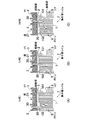
図2は、本発明の一実施形態である集中巻コイル7の結線部の断面図である。紙面左が集中巻コイル7の内周側であり、紙面右が外周側である。
図2(A)は、U相を結線した状態を示す。集中巻コイル7は、電磁鋼板を積層したコア5と、コア5の側面外周に覆われたボビン6と、ボビン6の凹部に絶縁被膜導線1が巻回された固定子巻線とを備える。また、絶縁被膜導線1のコイル端末101,102は、結線板2と4つの導体3(U相、V相、W相、中性点)の何れかとの双方に挿通されている。ここで、4つの導体3は、固定子の軸方向端部(コイルエンド部)に配置できるように、径が互いに異なる略円形であり、同一平面上に一段で配列されている。また、3つの導体3(U相、V相、W相)は、ボビン6の幅に略一致しており、中性点(P)の導体3は、コア5を連結する継鉄部の幅に略一致している。このため、4つの導体3は、集中巻固定子8の径方向の幅の範囲内に配置されている。
FIG. 2 is a cross-sectional view of the connection portion of the concentrated
FIG. 2A shows a state in which the U phase is connected. The concentrated
巻き始めコイル端末101は、結線板2の上に配置されている最外周側の導体3に接続され、中性点Pを形成する。巻き終わりコイル端末102は、結線板2の上に配置されている最内周側の導体3に接続され、U相を形成する。中性点Pでは図示していないが、U相、中性点Pともにコイル端末10が挿通する位置に、結線板2には貫通孔20が開けられ、導体3には接続孔30が開けられている。この構造により、結線板2を挟んで絶縁被膜導線1と導体3との相間絶縁が保たれている。また、結線板2は、壁21が設けられ、それぞれの導体の位置決めを行うと共に、導体3相互間の相間絶縁を確保している。
The winding
図2(B)はV相を結線した状態を示す。巻き終わりコイル端末102が結線板2の上に配置されている最内周側から2番目の導体3に接続され、V相を形成する。それ以外はU相と同じ構成である。図2(C)はW相を結線した状態を示す。巻き終わりコイル端末102が結線板2の上に配置されている最内周側から3番目の導体3に接続され、W相を形成する。それ以外はU相と同じ構成である。
また、各コイルの巻き終わりは、コイルの幅方向中央部で終了しており、U相の場合は図面左側斜め方向に延長して巻き終わりコイル端末102が引き出され、V相の場合には、コイルの幅方向中央部から略直線的に巻き終わりコイル端末102が引き出され、W相の場合には、図面右側斜め方向に延長して巻き終わりコイル端末102が引き出されている。
FIG. 2B shows a state in which the V phase is connected. The winding
In addition, the end of winding of each coil ends at the central portion in the width direction of the coil. In the case of the U phase, the winding
図3は、回転電機100の集中巻固定子8に使用されるコイル端末10と、コイルを互いに接続する導体3との接続部の断面図である。接続部は、接続孔30が開けられた導体3と、貫通孔20が開けられた結線板2と、コイル端末10と、接合部である溶接部4とを備える。結線板2は、絶縁材料で形成され、結線板2の表面には導体3が配置され、円環状である。貫通孔20と接続孔30とは、同軸上に開孔され、コイル端末10が挿通される。結線板2の反対側の導体3の表面にコイル端末10の端部が配置される。溶接部4は、TIG(Tungsten Inert Gas)溶接によりコイル端末10の全周を溶融してできたものであり、溶融金属が接続孔30の内周面全周にA点の深さまで流れ込んでいる。これにより、溶接部4は、コイル端末10と導体3とを機械的、電気的に接続する。
FIG. 3 is a cross-sectional view of a connection portion between the
また、結線板の沿面距離を確保する目的で、貫通孔20の直径は接続孔30よりも大きく設定されており、コイル端末10が貫通孔20の内周面に接触することを回避している。例えば、本実施形態では、コイル端末10の直径は約1.2mmであり、溶接による溶融物が溶けて流れ込んで留まるのに適正な約0.3mmのすき間を設けて、接続孔30の直径は約1.8mmとしている。また、導体3の接続孔30の位置決めと、コイル端末10の位置決め誤差を許容するように、貫通孔20の直径を3mmとした。
Further, for the purpose of ensuring the creepage distance of the connection board, the diameter of the through
図4は、コイル端末10と導体3との接続部の斜視図である。
図4(A)は、導体3の断面が矩形状体31である場合を示しており、結線板2の表面に配置された導体3には接続孔30が開孔され、接続孔30にはコイル端末10が挿通し、コイル端末10の端部が導体3の上面から突出している。この後、TIG溶接によりコイル端末10の端部、及び接続孔30の周辺を溶融させてコイル端末10と導体3とを接合する。なお、結線板2の一部であるL字状の断面が図示されている。
FIG. 4 is a perspective view of a connection portion between the
FIG. 4A shows a case where the cross section of the
図4(B)は、導体3の断面形状が円形状である円形状体32を用いた場合を示しており、基本的な形態は図4(A)と同じである。略矩形状体31と円形状体32とを比較した場合、導体3の断面積を等しくすると、略矩形状体31の方が円形状体32よりも導体3の高さ寸法を小さくすることができ、コイルエンドを小さくすることができる。
FIG. 4B shows a case where a
図5(A)は、集中巻固定子に使用される分割コアの斜視図であり、図5(B)は、集中巻コイルの斜視図である。図5(A)において、コア5は、電磁鋼板を回転電機100(図1)の軸方向に積層して形成され、渦電流損を低減している。ボビン6は、固定子の径方向に直交する4面を覆うように、四角形状に貫通した絶縁物である。また、四角形状のボビン6の各辺は、凹部状に形成されている。また、ボビン6の上部には、巻始めのコイル端末10が挿入される切り欠き60が設けられ、上下部の4カ所には、開口部が設けられている。
FIG. 5A is a perspective view of a split core used for a concentrated winding stator, and FIG. 5B is a perspective view of a concentrated winding coil. 5A, the
図5(B)において、集中巻コイル7は、断面が略矩形状の絶縁被膜導線1をボビン6の凹部(すなわち、コア5のティース部)に巻回したものである。これにより、コイルが巻回される面に垂直な方向(集中巻固定子8の径方向)に磁界が発生する。集中巻コイル7は、ボビン6に絶縁被膜導線1が巻回されることにより、コア5と絶縁被膜導線1との間の絶縁性能を保っている。この集中巻コイル7は、1個のコイルで巻き始めコイル端末101と巻き終わりコイル端末102との2つのコイル端末10を有している。コア5の継鉄部は、コア5同士を連結して円筒状の集中巻固定子8を構成するためのものである。すなわち、固定子巻線は、分割されたコア5に巻回され、固定子鉄心は、コア5が継鉄部で円筒状に連結されて構成され、導体3は、固定子鉄心の軸方向に垂直な側面に配設される。なお、絶縁被膜導線1の断面は、円形状、略矩形状のどちらでもよいが、本実施形態では、コアスロット内のコイル占積率向上の目的で、略矩形状の場合について述べている。
In FIG. 5 (B), the concentrated winding
絶縁皮膜を剥離してコイル端末10と導体3(図3)とを接合する必要があるため、図6を用いて、コイル端末10の処理工程について述べる。図6は、断面が略矩形状の絶縁被膜導線1の皮膜剥離の工程を示す斜視図である。絶縁被膜導線1の断面を略矩形状にすることにより、コイルの占積率が高められる。図6(A)は、絶縁被膜導線1の先端まで絶縁皮膜11で被覆されているコイル端末10を示している。断面が略矩形状であるため、絶縁被膜導線1の角部が貫通孔20、あるいは接続孔30(図3)の縁に当たりやすく、孔を通し難い形状である。そこで、図6(B)に示すように、コイル端末10の断面形状成形部12をダイス(図示せず)で加圧して、断面を略円形状に成形する。この状態では断面形状成形部12には絶縁皮膜11が被覆されている。次に、図6(C)に示すように皮膜剥離部13の箇所に内周回転のカッター(図示せず)を当てて,絶縁皮膜11を剥離する。こうすることにより断面が略矩形状の絶縁被膜導線1で、絶縁皮膜が剥離された断面が円形状のコイル端末10を得ることができる。
Since it is necessary to peel the insulating film and join the
以上説明したように、本実施形態によれば、集中巻固定子8を構成する絶縁皮膜導線1のコイル端末10の断面形状を円形のまま、あるいは略円形に成形し、かつコイル端末10の絶縁皮膜を剥離し、絶縁材料で形成された結線板2に貫通孔20を開け、この結線板2の表面に配置された導体3に、接続孔30を開ける。次に、コイル端末10を貫通孔20と接続孔30との双方に挿通し、コイル端末10と導体3とを溶接あるいはろう付けなどで接合する。これにより集中巻固定子8のコイルエンドの寸法が小さくなる。
As described above, according to this embodiment, the cross-sectional shape of the
巻き終わりコイル端末102の各引き出し位置の半径をU相、V相、W相、中性点毎に統一したので、導体3を円形にすることができボビン6の幅で3つの導体3を配置することができ、継鉄部の径方向幅を利用して中性点Pの導体3を配置することができる。したがって、集中巻固定子8の径方向の幅を有効に利用して導体3を配置することができる。また、複数の導体3を1段で配置することができるので、コイルエンドの長さを短くすることができる。すなわち、コイルエンドの回転軸方向の長さを短くすることができるので、回転電機30の回転時の軸振動を小さくすることができる。このため、高速回転しても軸振動が小さくなって安定した運転を行うことができる。また、結線板2を導体3とコイルとの間に挿入したので、空間距離をかせぐことなく、絶縁を高めることができ、結線板2に壁21を設けて導体3相互間の絶縁を高めることができる。これらにより、モータ特性をそのままに小型化を図ることができ、構造を簡単にしたため、生産の信頼性を向上することができる。
Since the radius of each drawing position of the winding
(第2実施形態)
第1実施形態は、接続孔30を設けた導体3と、コイル端末10とを溶接したのみであるが、接続孔30に凸部を設けてコイル端末10との接合面積を増加させることができる。図7は、第2実施形態のコイル端末10と凸部33を設けた導体3aとの接続部の斜視図である。
断面が略矩形状の導体3aが結線板2の表面に配置されており、導体3aは凸部33を形成して接続孔30が開けられている。接続孔30にはコイル端末10が挿通し、コイル端末10の端部が導体3の上部に突出している。この挿通後、TIG溶接によりコイル端末10の端部および接続孔30周辺を溶融させてコイル端末10と導体3aとを接合する。凸部33を導体3aに形成したことにより、接続孔30の内周面の軸方向長さが長くなって接続面積が増加し、接続信頼性がさらに増加する。
(Second Embodiment)
Although 1st Embodiment only welded the
A conductor 3a having a substantially rectangular cross section is disposed on the surface of the
(第3実施形態)
第1実施形態、及び第2実施形態は、貫通孔20の内径、及び接続孔30の内径を一定にしていたが、テーパ部を設け、作りやすくすることができる。
図8は、コイル端末10と導体3との接続部の断面図を示している。結線板2の上には導体3bが配置され、結線板2には貫通孔20が開けられ、導体3には接続孔30が開けられ,貫通孔40及び接続孔30を通じて導体3bの上側にコイル端末10の端部が配置される。コイル端末10の直径は約1.2mmであり、接続孔30の直径は約1.8mmであり、貫通孔20の直径は約3mmである。貫通孔20と接続孔30とにはそれぞれ角度30度のテーパ301,401が設けられ、孔の入り口側の径が大きくなっており、コイル端末10を挿入し易くなっている。コイル端末10と導体3はTIG溶接により接続され、溶接部4を得る。なお、本実施形態ではTIG溶接による接続としたが、ろう付けによる接続でもよい。
(Third embodiment)
In the first embodiment and the second embodiment, the inner diameter of the through-
FIG. 8 shows a cross-sectional view of a connection portion between the
また,本実施形態では高電圧電動機を前提として、壁21を設けた結線板2を用いたが、壁21による絶縁を必要としない低電圧電動機では、結線板2を設けないで孔を有する導体3に直接コイル端末を挿通して、導体3とコイル端末10とを接続してもよい。このような構造にすることにより固定子のコイルエンドの寸法が小さくなり、小型の固定子を得ることができる。
In the present embodiment, the
(比較例)
一般的に高電圧に対応させるためには、導体間の空間距離や沿面距離を確保して絶縁特性を満足させる必要があり、例えば、回転電機では、以下の3つの技術が考えられている。第1は、バスバーに端子を設け、この端子部分にコイル端末を接続した構造である。第2は、バスリングと呼ばれる導体に別部品の端子を接続し、この端子とコイル端末とを接続した構造である。これらは、端子の存在により、固定子のコイルエンド高さ方向の寸法が大きい。第3は導線を直角方向に二回連続折り曲げて導線の端部とコイル端末とを接続した構造である。これは、コイルエンドの接続部の寸法が回転子の径方向、軸方向ともに大きくなりがちである。何れも絶縁材料で形成された結線板の上に導体を配置して絶縁特性を満足させている。
(Comparative example)
In general, in order to cope with a high voltage, it is necessary to ensure a space distance and a creepage distance between conductors to satisfy an insulation characteristic. For example, the following three technologies are considered in a rotating electric machine. 1st is the structure which provided the terminal in the bus bar and connected the coil terminal to this terminal part. The second is a structure in which a terminal of another component is connected to a conductor called a bus ring, and this terminal is connected to a coil terminal. These have large dimensions in the coil end height direction of the stator due to the presence of the terminals. The third is a structure in which the end of the conducting wire is connected to the coil terminal by bending the conducting wire twice in a perpendicular direction. This tends to increase the size of the coil end connection in both the radial and axial directions of the rotor. In any case, a conductor is arranged on a connection board made of an insulating material to satisfy the insulating characteristics.
(変形例)
本発明は前記した実施形態に限定されるものではなく、例えば以下のような変形が可能である。
前記各実施形態は、集中巻固定子としたが、図3の結線方法については、分布巻きでも適用することができる。また、前記各実施形態はY結線としたが、中性点Pが無いΔ結線にすることもできる。また、前記各実施形態は三相を前提として説明したがn相の回転電機に対しても適用することができる。
(Modification)
The present invention is not limited to the above-described embodiment, and for example, the following modifications are possible.
In each of the above embodiments, the concentrated winding stator is used. However, the connection method shown in FIG. 3 can be applied to distributed winding. Moreover, although each said embodiment was set as Y connection, it can also be set as (DELTA) connection without the neutral point P. FIG. Moreover, although each said embodiment demonstrated on the premise of three phases, it is applicable also to an n-phase rotary electric machine.
1 絶縁被膜導線
2 結線板
3,3a,3b 導体
4 溶接部(接合部)
5 コア
6 ボビン
7 集中巻コイル(固定子巻線)
8 集中巻固定子
9 回転子
10 コイル端末
11 絶縁皮膜
12 断面形状成形部
13 皮膜剥離部
20 貫通孔
21 壁
30 接続孔
31 矩形状体
32 円形状体
33 凸部
60 切り欠き
100 回転電機
101 巻き始めコイル端末
102 巻き終わりコイル端末
301,401 テーパ
DESCRIPTION OF
5 core 6
DESCRIPTION OF
Claims (11)
前記4つの導体は、前記コイル端末が挿通する孔を複数設けた径が異なる略円形であり、同一平面上に配設され、
前記固定子巻線は、コイル端末の断面形状が略円形に形成され、
前記コイル端末は、絶縁被膜導線の絶縁皮膜が剥離され、
前記導体は、前記孔の周縁部に凸部を設け、該凸部の裏面側にテーパが形成され、前記コイル端末と前記凸部とが溶接部を形成している
ことを特徴とする回転電機用の固定子。 A plurality of stator windings arranged in an annular shape, and four conductors that connect the coil ends of the stator windings to the U phase, the V phase, the W phase, and the three-phase Y connection as neutral points thereof. A stator with
The four conductors are substantially circular with different diameters provided with a plurality of holes through which the coil terminals are inserted, and are arranged on the same plane,
The stator winding is formed so that the cross-sectional shape of the coil terminal is substantially circular,
In the coil terminal, the insulating film of the insulating film conductor is peeled off,
The electric conductor is provided with a convex portion at a peripheral portion of the hole , a taper is formed on the back side of the convex portion, and the coil terminal and the convex portion form a welded portion. Stator.
前記分割コアは、継鉄部で円筒状に連結され、
前記導体は、前記連結されて形成された固定子鉄心の軸方向に垂直な側面に配設されていることを特徴とする請求項1に記載の回転電機用の固定子。 The plurality of stator windings are respectively wound around a divided core divided into a plurality of parts,
The split core is connected in a cylindrical shape with a yoke part,
2. The stator for a rotating electrical machine according to claim 1, wherein the conductor is disposed on a side surface perpendicular to the axial direction of the stator core formed by the connection.
前記コイル端末の部分が、略円形の断面形状に形成されていることを特徴とする請求項1に記載の回転電機用の固定子。 The stator winding is formed by winding an insulating film conductor having a substantially rectangular cross section,
The stator for a rotating electrical machine according to claim 1, wherein the coil terminal portion is formed in a substantially circular cross-sectional shape.
前記固定子の内部で回転可能な回転子とを備えた回転電機。 A stator for a rotating electrical machine according to claim 1;
A rotating electrical machine including a rotor that is rotatable inside the stator.
Priority Applications (4)
| Application Number | Priority Date | Filing Date | Title |
|---|---|---|---|
| JP2007302780A JP5140389B2 (en) | 2007-11-22 | 2007-11-22 | Stator for rotating electric machine and rotating electric machine using the same |
| US12/275,839 US7936100B2 (en) | 2007-04-02 | 2008-11-21 | Stator for rotating machine and rotating machine using the same |
| EP08020313.6A EP2063516B1 (en) | 2007-11-22 | 2008-11-21 | Stator for rotating machine and rotating machine using the same |
| CN200810182169.8A CN101442230B (en) | 2007-11-22 | 2008-11-24 | Stator for rotating machine and rotating machine using the same |
Applications Claiming Priority (1)
| Application Number | Priority Date | Filing Date | Title |
|---|---|---|---|
| JP2007302780A JP5140389B2 (en) | 2007-11-22 | 2007-11-22 | Stator for rotating electric machine and rotating electric machine using the same |
Publications (2)
| Publication Number | Publication Date |
|---|---|
| JP2009131025A JP2009131025A (en) | 2009-06-11 |
| JP5140389B2 true JP5140389B2 (en) | 2013-02-06 |
Family
ID=40394206
Family Applications (1)
| Application Number | Title | Priority Date | Filing Date |
|---|---|---|---|
| JP2007302780A Expired - Fee Related JP5140389B2 (en) | 2007-04-02 | 2007-11-22 | Stator for rotating electric machine and rotating electric machine using the same |
Country Status (3)
| Country | Link |
|---|---|
| EP (1) | EP2063516B1 (en) |
| JP (1) | JP5140389B2 (en) |
| CN (1) | CN101442230B (en) |
Families Citing this family (18)
| Publication number | Priority date | Publication date | Assignee | Title |
|---|---|---|---|---|
| JP5232547B2 (en) * | 2008-06-30 | 2013-07-10 | 日立オートモティブシステムズ株式会社 | Rotating electric machine |
| JP5548377B2 (en) * | 2009-03-31 | 2014-07-16 | 日立オートモティブシステムズ株式会社 | Rotating electric machine |
| JP5683008B2 (en) * | 2011-05-26 | 2015-03-11 | アスモ株式会社 | Motor core, stator and stator manufacturing method |
| JP5713836B2 (en) * | 2011-08-05 | 2015-05-07 | 株式会社安川電機 | Rotating electric machine and wiring board for rotating electric machine |
| EP2555390A2 (en) * | 2011-08-05 | 2013-02-06 | Kabushiki Kaisha Yaskawa Denki | Rotating electrical machine with wire connecting substrate |
| JP5585943B2 (en) * | 2011-08-05 | 2014-09-10 | 株式会社安川電機 | Rotating electric machine and wiring board for rotating electric machine |
| JP5348199B2 (en) * | 2011-08-05 | 2013-11-20 | 株式会社安川電機 | Manufacturing method of rotating electrical machine and manufacturing method of wiring board of rotating electrical machine |
| JP5775173B2 (en) * | 2011-11-22 | 2015-09-09 | 本田技研工業株式会社 | Rotating electric machine |
| JP2013162673A (en) * | 2012-02-07 | 2013-08-19 | Toshiba Industrial Products Manufacturing Corp | Method for manufacturing stator of rotary electric machine |
| JP5853875B2 (en) * | 2012-06-20 | 2016-02-09 | 日立金属株式会社 | Power collection and distribution ring and electric motor |
| JP5776664B2 (en) | 2012-10-19 | 2015-09-09 | 株式会社安川電機 | Rotating electric machine, stator assembly, and wiring board |
| JP5858302B2 (en) * | 2014-03-17 | 2016-02-10 | 株式会社安川電機 | Rotating electric machine and wiring board for rotating electric machine |
| JP6498775B2 (en) * | 2015-09-11 | 2019-04-10 | 日立オートモティブシステムズ株式会社 | Stator and rotating electric machine |
| JP6416965B1 (en) * | 2017-03-31 | 2018-10-31 | 本田技研工業株式会社 | Coil winding parts and rotating electric machine |
| CN111033959B (en) * | 2017-09-28 | 2022-04-05 | 日本电产株式会社 | Bus bar unit and motor |
| JP2019068558A (en) * | 2017-09-29 | 2019-04-25 | 日本電産株式会社 | Motor, and manufacturing method of motor |
| CN111628591A (en) * | 2019-02-28 | 2020-09-04 | 株式会社村田制作所 | Stator, stator assembly and converter of electric energy and mechanical energy |
| US11626766B2 (en) | 2020-05-22 | 2023-04-11 | Hitachi Astemo, Ltd. | Power connection with overmolded axially adjusted connecting rings |
Family Cites Families (12)
| Publication number | Priority date | Publication date | Assignee | Title |
|---|---|---|---|---|
| JPS6015069A (en) * | 1983-07-06 | 1985-01-25 | Kobe Steel Ltd | Circumferential fillet welding method of al pipe |
| JP3651491B2 (en) | 1995-02-17 | 2005-05-25 | 株式会社安川電機 | Motor coil terminal fixing method |
| DE19647559A1 (en) | 1996-11-18 | 1997-11-27 | Mannesmann Sachs Ag | Stator of electric machine |
| JP2001169492A (en) * | 1999-12-09 | 2001-06-22 | Mitsubishi Electric Corp | Squared insulated coating conductor and method for making it |
| JP3836655B2 (en) * | 2000-02-09 | 2006-10-25 | 三菱電機株式会社 | Conductor welded structure |
| JP2001275288A (en) * | 2000-03-27 | 2001-10-05 | Matsushita Electric Ind Co Ltd | Stator of motor |
| JP2003079079A (en) | 2001-09-03 | 2003-03-14 | Honda Motor Co Ltd | Current collecting/distributing ring for rotary electric machine |
| JP2005086985A (en) * | 2003-09-11 | 2005-03-31 | Asmo Co Ltd | Stator and brushless motor using stator |
| JP2006204029A (en) * | 2005-01-21 | 2006-08-03 | Sumitomo Electric Ind Ltd | Structure of connection and fixation between wire and connected material |
| JP2007135340A (en) * | 2005-11-11 | 2007-05-31 | Sumitomo Electric Ind Ltd | Stator of rotary electric machine |
| JP4758798B2 (en) * | 2006-03-24 | 2011-08-31 | 住友電気工業株式会社 | Bus bar coupling unit for rotating electrical machine stator |
| JP5016969B2 (en) | 2007-04-25 | 2012-09-05 | 日立オートモティブシステムズ株式会社 | Power distribution parts for rotating electrical machines |
-
2007
- 2007-11-22 JP JP2007302780A patent/JP5140389B2/en not_active Expired - Fee Related
-
2008
- 2008-11-21 EP EP08020313.6A patent/EP2063516B1/en not_active Not-in-force
- 2008-11-24 CN CN200810182169.8A patent/CN101442230B/en not_active Expired - Fee Related
Also Published As
| Publication number | Publication date |
|---|---|
| EP2063516B1 (en) | 2015-07-22 |
| CN101442230A (en) | 2009-05-27 |
| CN101442230B (en) | 2014-12-10 |
| EP2063516A3 (en) | 2013-05-01 |
| JP2009131025A (en) | 2009-06-11 |
| EP2063516A2 (en) | 2009-05-27 |
Similar Documents
| Publication | Publication Date | Title |
|---|---|---|
| JP5140389B2 (en) | Stator for rotating electric machine and rotating electric machine using the same | |
| US7936100B2 (en) | Stator for rotating machine and rotating machine using the same | |
| JP4486678B2 (en) | Rotating motor armature, rotating motor and manufacturing method thereof | |
| JP6033582B2 (en) | Stator and stator manufacturing method | |
| JP5704394B2 (en) | Rotating electric machine stator | |
| US10622861B2 (en) | Stator and bus bar connector configuration | |
| JP5214064B2 (en) | Inverter integrated drive module | |
| JP4662141B2 (en) | Rotating electric machine including stator | |
| JP2011151953A (en) | Stator of dynamo-electric machine | |
| US11605993B2 (en) | Rotary motors incorporating flexible printed circuit boards | |
| JP4254152B2 (en) | AC motor stator | |
| JP7107663B2 (en) | Rotating electric machine stator | |
| JP2017221077A (en) | Rotor for rotary electric machine | |
| JP2014011901A (en) | Stator, motor, and method of manufacturing stator | |
| US8466598B2 (en) | Electric rotating machine | |
| JP2006187164A (en) | Rotary electric machine | |
| JP2009106008A (en) | Stator for rotating electric machine | |
| JP2014207840A (en) | Dynamo-electric machine and stator for use therein | |
| JP2009077480A (en) | Rotary motor | |
| JP2005051999A (en) | Stator of rotary electric machine | |
| JP7198985B2 (en) | motor | |
| WO2014157621A1 (en) | Stator structure | |
| JP6080964B2 (en) | Rotating electric machine stator | |
| US11050317B2 (en) | Rotary electric machine and manufacturing method thereof | |
| JP2019009962A (en) | Wire connection structure of three-phase motor, wire connection method, and the three-phase motor |
Legal Events
| Date | Code | Title | Description |
|---|---|---|---|
| A621 | Written request for application examination |
Free format text: JAPANESE INTERMEDIATE CODE: A621 Effective date: 20100316 |
|
| A131 | Notification of reasons for refusal |
Free format text: JAPANESE INTERMEDIATE CODE: A131 Effective date: 20120228 |
|
| A977 | Report on retrieval |
Free format text: JAPANESE INTERMEDIATE CODE: A971007 Effective date: 20120229 |
|
| A521 | Written amendment |
Free format text: JAPANESE INTERMEDIATE CODE: A523 Effective date: 20120427 |
|
| A131 | Notification of reasons for refusal |
Free format text: JAPANESE INTERMEDIATE CODE: A131 Effective date: 20120821 |
|
| A521 | Written amendment |
Free format text: JAPANESE INTERMEDIATE CODE: A523 Effective date: 20120927 |
|
| TRDD | Decision of grant or rejection written | ||
| A01 | Written decision to grant a patent or to grant a registration (utility model) |
Free format text: JAPANESE INTERMEDIATE CODE: A01 Effective date: 20121113 |
|
| A01 | Written decision to grant a patent or to grant a registration (utility model) |
Free format text: JAPANESE INTERMEDIATE CODE: A01 |
|
| A61 | First payment of annual fees (during grant procedure) |
Free format text: JAPANESE INTERMEDIATE CODE: A61 Effective date: 20121119 |
|
| R150 | Certificate of patent or registration of utility model |
Ref document number: 5140389 Country of ref document: JP Free format text: JAPANESE INTERMEDIATE CODE: R150 Free format text: JAPANESE INTERMEDIATE CODE: R150 |
|
| FPAY | Renewal fee payment (event date is renewal date of database) |
Free format text: PAYMENT UNTIL: 20151122 Year of fee payment: 3 |
|
| LAPS | Cancellation because of no payment of annual fees |