JP5139366B2 - Thin acoustoelectric transducer - Google Patents
Thin acoustoelectric transducer Download PDFInfo
- Publication number
- JP5139366B2 JP5139366B2 JP2009107545A JP2009107545A JP5139366B2 JP 5139366 B2 JP5139366 B2 JP 5139366B2 JP 2009107545 A JP2009107545 A JP 2009107545A JP 2009107545 A JP2009107545 A JP 2009107545A JP 5139366 B2 JP5139366 B2 JP 5139366B2
- Authority
- JP
- Japan
- Prior art keywords
- corners
- hollow portion
- vibrating membrane
- thin
- diaphragm
- Prior art date
- Legal status (The legal status is an assumption and is not a legal conclusion. Google has not performed a legal analysis and makes no representation as to the accuracy of the status listed.)
- Active
Links
- 239000012528 membrane Substances 0.000 claims description 48
- 230000002093 peripheral effect Effects 0.000 claims description 35
- 238000006073 displacement reaction Methods 0.000 claims description 9
- 230000005415 magnetization Effects 0.000 claims description 6
- 239000010408 film Substances 0.000 description 49
- 239000010409 thin film Substances 0.000 description 19
- 230000035699 permeability Effects 0.000 description 5
- 239000000463 material Substances 0.000 description 4
- 230000005405 multipole Effects 0.000 description 3
- 230000007935 neutral effect Effects 0.000 description 3
- 239000004745 nonwoven fabric Substances 0.000 description 3
- 239000011347 resin Substances 0.000 description 3
- 229920005989 resin Polymers 0.000 description 3
- 230000004043 responsiveness Effects 0.000 description 3
- RYGMFSIKBFXOCR-UHFFFAOYSA-N Copper Chemical compound [Cu] RYGMFSIKBFXOCR-UHFFFAOYSA-N 0.000 description 2
- XEEYBQQBJWHFJM-UHFFFAOYSA-N Iron Chemical compound [Fe] XEEYBQQBJWHFJM-UHFFFAOYSA-N 0.000 description 2
- 230000002159 abnormal effect Effects 0.000 description 2
- 238000007796 conventional method Methods 0.000 description 2
- 239000011889 copper foil Substances 0.000 description 2
- 238000010586 diagram Methods 0.000 description 2
- 229910052751 metal Inorganic materials 0.000 description 2
- 239000002184 metal Substances 0.000 description 2
- 230000005236 sound signal Effects 0.000 description 2
- 125000003118 aryl group Chemical group 0.000 description 1
- 238000006243 chemical reaction Methods 0.000 description 1
- 239000000428 dust Substances 0.000 description 1
- 230000000694 effects Effects 0.000 description 1
- 238000003780 insertion Methods 0.000 description 1
- 230000037431 insertion Effects 0.000 description 1
- 229910052742 iron Inorganic materials 0.000 description 1
- 239000006247 magnetic powder Substances 0.000 description 1
- 238000000034 method Methods 0.000 description 1
- -1 polyethylene terephthalate Polymers 0.000 description 1
- 229920000139 polyethylene terephthalate Polymers 0.000 description 1
- 239000005020 polyethylene terephthalate Substances 0.000 description 1
- 229920001721 polyimide Polymers 0.000 description 1
- 238000004080 punching Methods 0.000 description 1
- 229910052761 rare earth metal Inorganic materials 0.000 description 1
- 150000002910 rare earth metals Chemical class 0.000 description 1
- 230000001105 regulatory effect Effects 0.000 description 1
- 229910000859 α-Fe Inorganic materials 0.000 description 1
Images


Landscapes
- Audible-Bandwidth Dynamoelectric Transducers Other Than Pickups (AREA)
- Diaphragms For Electromechanical Transducers (AREA)
Description
本発明は、平面スピーカ等の薄型音響電気機械変換器に関する。 The present invention relates to a thin acousto-electric transducer such as a flat speaker.
従来、平面スピーカとして、例えば特許文献1に開示されたものがある。この従来技術によれば、一面が開口された扁平直方体状のケース本体内に、当該開口部側から、方形板状の前面(表面)側永久磁石板と、方形シート状の前面側緩衝シートと、方形シート状の振動膜と、方形シート状の背面(裏面)側緩衝シートと、方形板状の背面側永久磁石板とが、この順番で収容される。この状態で、ケース本体の開口部が、概略方形板状の裏蓋によって閉鎖される。ここで、振動膜の表面には、コイルとしての蛇行状の導電パターンが形成されている。そして、このコイルの直線部分を直角に横切る磁界が生成されるように、それぞれの永久磁石板の振動膜と対向する側の面に、帯状のN極と帯状のS極とが交互に現れる平行縞状の多極着磁パターンが形成されている。さらに、前面側の永久磁石板のN極とS極との境界領域に、当該永久磁石板を貫通するように、多数の通気孔が設けられている。これと同様に、ケース本体の主面にも、当該主面を貫通するように、多数の通気孔が設けられている。なお、それぞれの緩衝シートは、通気性および柔軟性を有しており、このような緩衝シートとしては、例えば1枚または複数枚の不織布が採用される。
Conventionally, as a flat speaker, there exists what was disclosed by
即ち、この構成によれば、コイルに電流が流れると、フレミングの左手の法則に従って、当該コイルに振動膜の厚み方向に沿う機械力(電磁力)が作用する。これに付随して、振動膜が振動し、この結果、音波が発生する。詳しくは、前面側の永久磁石板に設けられた各通気孔と、ケース本体の主面に設けられた各通気孔と、を介して、外部に当該音波が放出される。なお、振動膜が振動する際に、当該振動膜が各永久磁石板に衝突して、雑音(異常音)が発生することが懸念されるが、これらの間には緩衝シートが設けられているので、そのような懸念は払拭される。また、特に、前面側の緩衝シートは、防塵用としても機能する。さらに、背面側については、塞がれた状態にあるので、高音域において良好な音響特性(音圧特性)が得られる、とされている。 That is, according to this configuration, when a current flows through a coil, a mechanical force (electromagnetic force) along the thickness direction of the diaphragm is applied to the coil according to Fleming's left-hand rule. Along with this, the vibrating membrane vibrates, and as a result, a sound wave is generated. Specifically, the sound wave is emitted to the outside through the air holes provided in the front permanent magnet plate and the air holes provided in the main surface of the case body. In addition, when the vibration film vibrates, there is a concern that the vibration film collides with each permanent magnet plate and noise (abnormal sound) is generated, but a buffer sheet is provided between them. So such concerns are dispelled. In particular, the buffer sheet on the front side also functions as a dust-proof material. Furthermore, since the back side is in a closed state, good acoustic characteristics (sound pressure characteristics) are obtained in the high sound range.
ところで、上述の従来技術において、振動膜は、その厚み方向にのみ振動し、面内方向へは変位しないようにすることが、肝要とされる。このため、当該従来技術では、図14(a)に概略的に示すように、振動膜1の外周縁が、ケース本体2の内周壁3によって、包囲されている。また、これら振動膜1の外周縁とケース本体2の内周壁3との間に余分な空間(遊び)が形成されぬよう、これら両者は可能な限り近接されている。
By the way, in the above-described prior art, it is important that the vibration film vibrate only in the thickness direction and not be displaced in the in-plane direction. For this reason, in the related art, the outer peripheral edge of the
しかしながら、このように振動膜1の外周壁とケース本体2の内周壁3とが近接されることによって、例えば図14(b)に誇張して示すように、当該ケース本体2内に振動膜1が組み込まれる際に、いわゆる位置ズレが生じ易い、という問題がある。即ち、振動膜1の四隅の少なくとも一部がケース本体2内から食み出した状態で、当該平面スピーカが組み立てられることがある。そうなると、当然に、振動膜1の振動が阻害されて、期待通りの音響特性が得られなくなる。
However, when the outer peripheral wall of the
また、たとえ当該位置ズレが生じていないとしても、従来技術では、別の問題がある。即ち、今、図14(a)に示したように、ケース本体2内に振動膜1が適切に組み込まれている、と仮定する。これにより、図15に拡大して示すように、振動膜1の長手方向(図15の上下方向)において、当該振動膜1の変位量がDa以下に抑えられ、併せて、振動膜1の短辺方向(図15の左右方向)において、当該振動膜1の変位量がDb以下に抑えられる、とする。ところが、これ以外の方向、例えば振動膜1の対角方向においては、当該振動膜1の最大変位量Dcは、長手方向および短辺方向それぞれの最大変位量DaおよびDbよりも大きい(Dc=(Da2+Db2)1/2)。つまり、振動膜1が変位する方向によっては、当該振動膜1は大きく変位する、という問題がある。
Further, even if the positional deviation does not occur, there is another problem in the conventional technique. That is, it is assumed that the
さらに、従来技術では、次のような問題もある。即ち、上述したように、振動膜1は、その表面に形成されたコイルに付随して振動する。従って、この振動膜1を詳細に観察すると、当該振動膜1のうち、コイルが形成されている部分については、高い応答性で振動し、そうでない部分については、応答性が低い。この応答性が低い部分には、振動膜1の四隅部分も含まれる。しかも、当該四隅部分は、振動する際に、大きな撓りを伴うため、音波への変換にはそれほど貢献しない。そうすると、振動膜1全体から見て、当該四隅部分は単なる負荷であるに過ぎず、却って邪魔な存在となる。このこともまた、音響特性に大きく影響し、特に低音域での特性に大きく影響する。
Further, the conventional technique has the following problems. That is, as described above, the vibrating
そこで、本発明は、振動膜を改良することによって、従来よりも良好な音響特性を得ることができる薄型音響電気機械変換器を提供することを、目的とする。 SUMMARY OF THE INVENTION Accordingly, an object of the present invention is to provide a thin acousto-electromechanical transducer capable of obtaining better acoustic characteristics than before by improving a vibrating membrane.
この目的を達成するために、本発明は、中空部を有する筐体と、この筐体の中空部内に設けられた振動膜と、を具備する。ここで、筐体の中空部は、略四角形の開口部を有しており、この開口部を一面とする概略直方体状とされている。そして、振動膜は、その外周縁が筐体の中空部の内周壁に包囲されることによって、その面内方向への変位が規制され、厚み方向(面外方向)にのみ変位可能とされている。さらに、振動膜は、可撓性を有しており、その表面には、コイルが形成されている。そして、このコイルは、筐体の中空部内に形成される磁界を横切る方向に延伸する部分を有している。このような薄型音響電気機械変換器において、本発明は、さらに、振動膜の四隅が面取り状に形成され、併せて、中空部の内周壁の四隅が当該振動膜の四隅に応じた形状とされたものである。 In order to achieve this object, the present invention includes a housing having a hollow portion and a vibration membrane provided in the hollow portion of the housing. Here, the hollow part of the housing has a substantially rectangular opening, and has a substantially rectangular parallelepiped shape with this opening as one surface. The diaphragm is restricted from being displaced in the in-plane direction by being surrounded by the inner peripheral wall of the hollow portion of the casing, and can only be displaced in the thickness direction (out-of-plane direction). Yes. Furthermore, the vibration film has flexibility, and a coil is formed on the surface thereof. And this coil has a part extended | stretched in the direction which crosses the magnetic field formed in the hollow part of a housing | casing. In such a thin acousto-mechanical transducer, the present invention further includes the four corners of the diaphragm being chamfered, and the four corners of the inner peripheral wall of the hollow portion being shaped according to the four corners of the diaphragm. It is a thing.
即ち、この構成によれば、例えば、コイルに電流が流れると、フレミングの左手の法則に従って、振動膜の厚み方向に沿う機械力が当該コイルに作用する。そして、このコイルに付随して、振動膜がその厚み方向に沿って振動し、この結果、音波が発生する。つまり、電流という電気エネルギを機械力という機械エネルギに変換し、ひいては音波に変換するための変換器、いわゆるスピーカ、が実現される。これとは反対に、振動膜に音波が当たることによって、当該振動膜に機械力が作用すると、振動膜がその厚み方向に沿って振動し、これに伴って、コイルも振動する。この結果、フレミングの右手の法則に従って、コイルに電流が流れる。つまり、音波が振動膜に当たることによる機械エネルギを電気エネルギに変換するための変換器、いわゆるマイクロホン、が実現される。 That is, according to this configuration, for example, when a current flows through a coil, a mechanical force along the thickness direction of the diaphragm is applied to the coil in accordance with Fleming's left-hand rule. Along with this coil, the vibrating membrane vibrates along its thickness direction, and as a result, a sound wave is generated. That is, a converter, that is, a so-called speaker, is realized for converting electric energy called current into mechanical energy called mechanical force, and eventually into sound waves. On the other hand, when a mechanical force is applied to the vibration film due to the sound wave hitting the vibration film, the vibration film vibrates along the thickness direction, and accordingly, the coil also vibrates. As a result, current flows through the coil according to Fleming's right-hand rule. That is, a converter for converting mechanical energy into electrical energy due to the sound wave hitting the vibrating membrane, a so-called microphone, is realized.
ところで、本発明においては、上述したように、振動膜の面内方向への変位を規制するために、当該振動膜の外周縁が筐体の中空部の内周壁に包囲されている。つまり、振動膜の外周縁と筐体の中空部の内周壁との間に余分な空間が形成されぬよう、これら両者間は可能な限り近接されている。従って、振動膜が筐体の中空部内に組み込まれる際に、上述した位置ズレが生じ易く、ゆえに、当該振動膜の四隅が中空部から食み出すことが懸念される。しかし、本発明では、振動膜の四隅が面取り状に形成されているので、当該四隅が中空部から食み出す可能性は低く、そのような懸念はない。 By the way, in the present invention, as described above, the outer peripheral edge of the vibration membrane is surrounded by the inner peripheral wall of the hollow portion of the casing in order to regulate the displacement of the vibration membrane in the in-plane direction. That is, the two are as close as possible to each other so that no extra space is formed between the outer peripheral edge of the vibrating membrane and the inner peripheral wall of the hollow portion of the housing. Therefore, when the vibration film is incorporated into the hollow portion of the housing, the above-described positional deviation is likely to occur, and therefore, there is a concern that the four corners of the vibration film protrude from the hollow portion. However, in the present invention, since the four corners of the vibration film are chamfered, the possibility that the four corners protrude from the hollow portion is low, and there is no such concern.
また、上述した従来技術では、振動膜が振動する際に、その四隅部分が邪魔になり、ひいては音響特性が悪化することが懸念されるが、本発明では、そのような懸念もない。即ち、本発明では、振動膜の四隅が面取り状に形成されているので、当該四隅部分が邪魔になることはなく、ゆえに、これが原因で音響特性が悪化することはない。 Further, in the above-described prior art, when the vibrating membrane vibrates, there are concerns that the four corner portions may become an obstacle and consequently the acoustic characteristics may be deteriorated. However, in the present invention, there is no such concern. That is, in the present invention, since the four corners of the vibration film are chamfered, the four corner portions do not get in the way, and therefore the acoustic characteristics are not deteriorated due to this.
なお、振動膜の四隅は、例えば直線状に排除されることによって、面取り状とされてもよい。また、R状に排除されることによって、例えば四半円状に形成されることによって、当該面取り状とされてもよい。さらに、多角形状に排除されることによって、面取り状とされてもよい。 Note that the four corners of the vibrating membrane may be chamfered, for example, by being eliminated in a straight line. Moreover, it may be set as the said chamfering shape by removing in R shape, for example by forming in quadrant shape. Furthermore, it may be chamfered by being excluded in a polygonal shape.
併せて、本発明においては、振動膜が収容される中空部の内周壁の四隅についても、当該振動膜の四隅に応じた形状とされている。これにより、当該四隅の方向においても、他の方向と同様に、振動膜の変位が精細に規制され、より良好な音響特性が得られる。 In addition, in the present invention, the four corners of the inner peripheral wall of the hollow portion in which the diaphragm is accommodated are also shaped according to the four corners of the diaphragm. Thereby, also in the directions of the four corners, the displacement of the diaphragm is finely regulated as in the other directions, and better acoustic characteristics can be obtained.
本発明は、スピーカに好適である。特に、振動膜が大きいスピーカほど、好適である。即ち、上述した従来技術において、振動膜の四隅部分が邪魔になって音響特性に悪影響を及ぼす傾向は、当該振動膜が大きいほど顕著になる。本発明は、このように不本意な傾向をもたらす大きな振動膜を有するスピーカに極めて有効である。 The present invention is suitable for a speaker. In particular, a loudspeaker with a large diaphragm is more suitable. That is, in the above-described prior art, the tendency that the four corner portions of the vibration film interfere with the acoustic characteristics becomes more prominent as the vibration film is larger. The present invention is extremely effective for a loudspeaker having a large vibration film that causes such an unintended tendency.
上述したように、本発明によれば、筐体の中空部内に振動膜が組み込まれる際に、位置ズレが生じたとしても、当該振動膜の四隅が中空部から食み出すことはない。従って、当該位置ズレによって音響特性が悪化する恐れのある従来技術とは異なり、確実に期待通りの音響特性を得ることができる。また、従来技術では、振動膜の四隅が邪魔になり、これによっても音響特性が悪化することが懸念されるが、本発明では、そのような懸念もない。さらに、本発明では、振動膜が収容される中空部の内周壁の四隅についても、当該振動膜の四隅に応じた形状とされることによって、より良好な音響特性を得ることができる。このように、本発明によれば、従来よりも確実に良好な音響特性を得ることができる。 As described above, according to the present invention, even when a positional deviation occurs when the vibration film is incorporated into the hollow part of the housing, the four corners of the vibration film do not protrude from the hollow part. Therefore, unlike the prior art in which the acoustic characteristics may be deteriorated due to the positional deviation, it is possible to reliably obtain the expected acoustic characteristics. In the prior art, there are concerns that the four corners of the vibration film become an obstacle, and this also deteriorates the acoustic characteristics, but in the present invention, there is no such concern. Furthermore, in the present invention, the four corners of the inner peripheral wall of the hollow portion in which the vibration film is accommodated can also have better acoustic characteristics by being shaped according to the four corners of the vibration film. As described above, according to the present invention, better acoustic characteristics can be obtained than in the past.
本発明が適用された平面スピーカ10の一実施形態について、以下に説明する。
An embodiment of the
図1に示すように、本実施形態に係る平面スピーカ10は、外観的には扁平の概略直方体状のものである。そして、構造的には、図2に示す組み立て図からも分かるように、1枚の振動膜12と、この振動膜12の両面を挟むように設けられた2枚の緩衝部材14および16と、これらの緩衝部材14および16をさらに外側から挟むように設けられた2つの永久磁石板18および20と、筐体としての前面カバー22および背面板24と、から成る。
As shown in FIG. 1, the
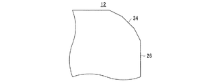
振動膜12は、図3にも示すように、概略矩形の薄膜26と、この薄膜26の前面および背面それぞれに形成された蛇行形状のコイル28および30と、から成る。このうち、薄膜26は、例えば厚さ寸法が30[μm]程度の可撓性を有する樹脂製フィルムである。このような樹脂製フィルムとしては、ポリエチレンテレフタレートフィルムや芳香族ポリイミドフィルム等がある。なお、この薄膜26の例えば上端縁の中央には、凹状の切欠32が設けられている。さらに、当該薄膜26の四隅34,34,…は、直線状に面取りされている。これら四隅34,34,…の面取り寸法、詳しくは薄膜26(振動膜12)の長手方向における面取り寸法hは、当該薄膜26の長手方向の辺寸法Hに合わせて適宜に決定され、例えば当該長手方向の辺寸法Hの1/20〜1/5程度とされる。そして、薄膜26の短辺方向における面取り寸法wもまた、当該薄膜26の短辺寸法Wに合わせて適宜に決定され、例えば当該短辺寸法Wの1/20〜1/5程度とされる。本実施形態においては、薄膜26の長手方向の辺寸法Hは、約290[mm]であり、当該長手方向の面取り寸法hは、約30[mm]、つまり長辺寸法Hの約1/10、とされている。そして、薄膜26の短辺寸法Wは、約200[mm]であり、短辺方向における面取り寸法wは、約30[mm]、つまり短辺寸法Wの約1/7、とされている。
As shown in FIG. 3, the
一方、コイル28および30は、例えばプリント配線技術によって形成された厚さ寸法が20[μm]〜50[μm]の銅箔パターンであり、薄膜26の下端縁近傍に設けられたスルーホール36を介して、互いに直列接続されている。そして、前面側のコイル28の端部38は、プラス端子として、切欠32の側縁近傍に設けられており、背面側のコイル30の端部40は、マイナス端子として、当該切欠32の反対側の側縁近傍に設けられている。なお、前面側のコイル28において、水平方向に沿って延伸するように多数設けられている直線部分と、背面側のコイル30において、同様に設けられている多数の直線部分とは、薄膜26を挟んで、互いに重なっている。そして、これら前面側のコイル28の直線部分と、背面側のコイル30の直線部分とは、互いに共役な関係にある。即ち、前面側のコイル28の端部38であるプラス端子と、背面側のコイル30の端部40であるマイナス端子と、の間に電流が流れると、この電流は、それぞれの直線部分において、互いに同じ方向に流れる。
On the other hand, the
図1および図2に戻って、前面側の緩衝部材14は、振動膜12(薄膜26)と略同じ大きさの概略矩形のシートであり、柔軟性および通気性を有する素材によって形成されている。このような素材としては、例えば不織布や和紙がある。また、図4にも示すように、当該前面側の緩衝部材14の四隅42,42,…も、振動膜12と同様に、直線状に面取りされている。なお、詳しい図示は省略するが、この緩衝部材14の四隅42,42,…の面取り寸法は、振動膜12の四隅34,34,…の面取り寸法hおよびwと略同じか、それよりも若干小さめとされている。また、図4は、緩衝部材14の前面を示す図であるが、背面は、当該前面と同じであるので、その図示についても省略する。
Returning to FIGS. 1 and 2, the front-
これと同様に、背面側の緩衝部材16もまた、振動膜12と略同じ大きさの概略矩形のシートであり、例えば不織布や和紙によって形成されている。そして、図5にも示すように、この背面側の緩衝部材16の四隅44,44,…も、直線状に面取りされている。さらに、その上端縁の中央には、振動膜12(薄膜26)と同様の切欠46が設けられている。なお、図5は、緩衝部材14の前面を示す図であるが、背面は、当該前面と同じであるので、その図示を省略する。
Similarly, the
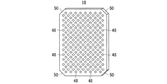
前面側の永久磁石板18は、適当な厚みを有しており、図6にも示すように、その表面は、振動膜12(薄膜26)と略同サイズの概略矩形とされている。そして、素材としては、フェライトや希土類磁性粉を含んだ樹脂磁石製またはゴム磁石製等であり、図示しないが、当該永久磁石板18の背面(緩衝部材14を介して振動膜12と対向する側の面)には、上述した前面側コイル28の各直線部分の並び方向に沿って帯状のN極と帯状のS極とが交互に現れる平行縞状の多極着磁パターンが形成されている。より詳しくは、この多極着磁パターン面の各N極と各S極との各境界部分は、ニュートラルゾーンであり、これらのニュートラルゾーンが、前面側コイル28の各直線部分と対向するように、当該多極着磁パターンが形成されている。さらに、各ニュートラルゾーン上の適宜の位置に、例えば千鳥格子状に、永久磁石板18をその前面側から背面側に貫通するように、音波放出孔としての複数の貫通孔48,48,…が設けられている。なお、多極着磁パターンを含む永久磁石板18の構成や、当該多極着磁パターンと前面側コイル28との位置関係、各貫通孔48,48,…の穿設位置については、公知であり、例えば特開平9−331596号公報にも開示されているので、これ以上の詳しい説明は省略する。さらにまた、この永久磁石板18の外周壁の四隅(角部)50,50,…も、振動膜12の四隅34,34,…に合わせて、面取りされている。
The front
背面側の永久磁石板20は、前面側の永久磁石板18と略同様であるが、図7にも示すように、その上端縁の中央に、振動膜12の切欠32に合わせた切欠52が設けられている点で、当該前面側の永久磁石板18と異なる。また、図示は省略するが、この背面側の永久磁石板20については、その前面(緩衝部材16を介して振動膜12と対向する側の面)に、多極着磁パターンが形成されている。これ以外は、多数の貫通孔54,54,…が設けられている点、および四隅(角部)56,56,…が面取りされている点を含め、前面側の永久磁石板18と同様であるので、詳細な説明を省略する。なお、図7は、永久磁石板20を前面側から見た図であるが、背面側から見た図も同じなるので、当該背面側から見た図を省略する。このことは、上述の図6についても、同様である。
The back side
前面カバー22は、鉄板等の高透磁率の金属製であり、図8にも示すように、背面側の一面が開口部57とされた概略直方体状の中空部58を有している。このような前面カバー22は、例えば打ち抜き曲げ加工または絞り加工によって、形成される。そして、この前面カバー22の中空部58内に、背面板24を除く全ての構成要素が収容される。特に、前面側の永久磁石板18は、その磁気吸着力によって、当該中空部58の奥面および内周壁に固定される。また、中空部58の内周壁の四隅(角部)64,64,…は、振動膜12の四隅34,34,…に合わせた形状とされている。具体的には、当該四隅64,64,…は、振動膜12の四隅34,34,…よりも僅かに外側に位置すると共に、永久磁石板18の四隅50,50,…と嵌合するように、形成されている。そして、この中空部58の内周壁の四隅64,64,…に合わせて、その裏側に当たる前面カバー22の外周壁の四隅(角部)68,68,…もまた、面取りされたのと同様の形状とされている。さらに、当該外周壁の四隅68,68,…に当たる部分のうち背面側には、開口部57の外側に突出するように、フランジ状の耳部70,70,…が設けられている。そして、それぞれの耳部70には、例えば図1(a)に示されるネジ72が挿通されるネジ挿通孔としての貫通孔74が設けられている。さらにまた、この前面カバー22にも、永久磁石板18の各貫通孔48,48,…と対向する位置に、音波放出孔としての複数の貫通孔76,76,…が設けられている。
The
背面板24は、図9にも示すように、矩形平板状であり、この背面板24もまた、高透磁率金属によって形成されている。そして、この背面板24の四隅には、上述のネジ72,72,…が螺着されるネジ孔78,78,…が設けられている。即ち、これらのネジ孔78,78,…に、前面カバー22側のネジ挿通孔としての各貫通孔74,74,…を介して、当該ネジ72,72,…が螺着されることで、前面カバー22と背面板24とが合体され、いわゆる筐体が形成される。そして、この筐体の内部においては、背面板24の内側面に、背面側の永久磁石板20が磁気吸着力によって固定される。このとき、当該背面側の永久磁石板20と、上述した前面側の永久磁石板18との間には、特に図1(d)に示すように、或る一定の大きさ、例えば数[mm]程度、の隙間80が、形成される。そして、この隙間80内に、振動膜12と、各緩衝部材14および16とが、互いに対向しつつ、適当な余裕(遊び)を持って、介在する。さらに、この背面板24にも、永久磁石板20の各貫通孔54,54,…と対向する位置に、音波放出孔としての複数の貫通孔82,82,…が設けられている。また、この背面板24の上端縁の中央には、端子台84が設けられている。
As shown in FIG. 9, the
端子台84は、プラス引出端子86と、マイナス引出端子88と、を有している。そして、このうちのプラス引出端子86に、振動膜12のプラス端子38が接続され、マイナス引出端子88に、当該振動膜12のマイナス端子40が接続される。なお、この接続は、図1(d)に符号90で示されるように、ワイヤ等の適当な導電線によって実現されるが、振動膜12の各端子38および40それぞれの銅箔パターンが端子台84の各引出端子86および88にまで延長されることによって実現されてもよい。そして、この振動膜12の各端子38および40と端子台84の各引出端子86および88との接続のために、上述の如く振動膜12(薄膜26)に切欠32が設けられ、併せて、背面側の緩衝部材16に切欠46が設けられ、さらに、背面側の永久磁石板20に切欠部52が設けられている。
The
このように構成された平面スピーカ10によれば、端子台84の各引出端子86および88が、図示しない外部配線に接続される。つまり、これら各引出端子86および88間に、オーディオ信号が入力される。すると、このオーディオ信号に従う電流が、前面側コイル28および背面側コイル30それぞれに流れる。そして、特にそれぞれのコイル28および30の直線部分において、当該電流は、磁界を直角に横切る方向に流れる。すると、フレミングの左手の法則に従って、振動膜12(薄膜26)の厚み方向に沿う機械力が、当該各コイル28および30に同時に作用する。しかも、この機械力が作用する方向は、各コイル28および30間で同じである。つまり、各コイル28および30は、同時かつ同じ方向に振動する。そして、これらのコイル28および30に付随して、振動膜12が振動し、この結果、音波が発生する。詳しくは、前面側に対しては、当該前面側の永久磁石板18に設けられた音波放出孔としての各貫通孔48,48,…と、同じく音波放出孔として前面カバー22に設けられた各貫通孔76,76,…と、を介して、外部に音波が放出される。そして、背面側に対しては、当該背面側の永久磁石板20に設けられた音波放出孔としての各貫通孔54,54,…と、同じく音波放出孔として背面板24に設けられた各貫通孔82,82,…とを介して、外部に音波が放出される。
According to the
なお、振動膜12が振動する際に、当該振動膜12が各永久磁石板18および20に衝突して、雑音(異常音)が発生することが懸念される。しかし、これら振動膜12と各永久磁石板18および20との間には、柔軟性を有する緩衝部材14および16が介在しているので、当該雑音の発生は防止される。また、この緩衝部材14および16が介在することによって、外部への音波の放出が阻害されることが懸念されるが、上述したように、当該緩衝部材14および16は通気性をも有するので、そのような懸念もない。その一方で、緩衝部材14および16は防塵手段(フィルタ)としても機能するので、外部から平面スピーカ10内(間隙80内)へのゴミ類の進入は防止される。
When the vibrating
ところで、良好な音響特性を得るには、振動膜12は、その面内方向への変位が規制され、厚み方向にのみ振動することが、理想とされる。そのために、当該振動膜12の外周縁は、図10(a)に示すように、何らとも接触しないフリーな状態で、前面カバー22の中空部58の内周壁によって包囲されている。特に、振動膜12の外周縁と中空部58の内周壁との間に余分な空間が形成されぬよう、これら両者間は可能な限り近接されている。なお、図10(a)においては、説明の便宜上、振動膜12について、輪郭のみ記載されている。このことは、後述する図10(b)についても、同様である。
By the way, in order to obtain good acoustic characteristics, it is ideal that the
ところが、上述の如く振動膜12の外周縁と中空部58の内周壁とが近接されることによって、図14(b)に示したような位置ズレが懸念される。しかしながら、本実施形態における振動膜12は、その四隅34,34,…が面取りされているので、当該位置ズレが生じたとしても、十分許容することができる。つまり、図14(b)に示した状態とは異なり、図10(b)に示すように、振動膜12の四隅34,34,…が中空部58(開口部57)から食み出し難い。従って、良好な音響特性を維持できる。
However, when the outer peripheral edge of the vibrating
また、たとえ位置ズレが生じないとしても、従来技術では、図15を参照しながら説明したように、振動膜1が変位する方向によって、当該振動膜1が大きく変位し、ひいては音響特性が悪化する、という問題がある。これに対して、本実施形態では、面取りされた振動膜12の四隅34,34,…に合わせて、中空部58の内周壁の四隅68,68,…が、当該振動膜12の四隅34,34,…と対向するように形成されている。詳しくは、図11に拡大して示すように、振動膜12の長手方向(図11の上下方向)において、当該振動膜12の外周縁と中空部58の内周壁との間の距離がDxであり、振動膜12の短辺方向(図11の左右方向)において、当該振動膜12の外周縁と中空部58の内周壁との間の距離がDyである、とすると、それ以外の方向、例えば振動膜12の対角方向においても、当該振動膜12の外周縁と中空部58の内周壁との間の距離を同程度のDzとすることができる。つまり、いずれの方向においても、振動膜12の変位量を同程度Dx,DyおよびDzに抑えることができる。これもまた、良好な音響特性を得るのに、大きく貢献する。
Further, even if no positional deviation occurs, in the related art, as described with reference to FIG. 15, the
さらに、従来技術では、振動膜が振動する際に、その四隅部分が邪魔になり、ひいては音響特性が悪化することが懸念されるが、本実施形態では、そのような懸念もない。即ち、本実施形態における振動膜12は、その四隅34,34,…が面取りされているので、当該四隅34,34,…が邪魔(単なる負荷)になることはなく、ゆえに、これが原因で音響特性が悪化することはない。
Furthermore, in the prior art, when the vibrating membrane vibrates, there is a concern that the four corner portions may become an obstacle and consequently the acoustic characteristics may deteriorate, but in this embodiment, there is no such concern. That is, since the four
以上のように、本実施形態によれば、振動膜12の四隅34,34,…が面取りされることによって、従来技術よりも良好な音響特性が得られる。つまり、当該振動膜12の四隅34,34,…を面取りするという極めて簡単な改良によって、絶大な効果を得ることができる。
As described above, according to this embodiment, the four
なお、本実施形態においては、振動膜12の四隅34,34,…を直線状に面取ることとしたが、これに限らない。例えば、図12に示すように、R状に面取りしてもよく、特に四半円状に面取りしてもよい。また、図13に示すように、多角形状に面取りしてもよい。このことは、各緩衝部材14および16についても、同様である。
In the present embodiment, the four
さらに、本実施形態では、振動膜12(薄膜26)の両面にコイル28および30が形成されるようにしたが、これに限らない。例えば、振動膜12の片面にのみコイルが形成されてもよいし、当該片面または両面それぞれに複数本のコイルが形成されてもよい。
Furthermore, in this embodiment, the
そして、本実施形態では、平面スピーカ10を例に挙げて説明したが、これとは反対の作用を奏するマイクロホンにも、本発明を適用することができる。
In the present embodiment, the
10 平面スピーカ
12 振動膜
18,20 永久磁石板
22 前面カバー
28,30 コイル
34 四隅
DESCRIPTION OF
Claims (5)
上記振動膜の四隅が面取り状に形成され、さらに、
上記中空部の内周壁の四隅が上記振動膜の四隅に応じた形状とされたこと、
を特徴とする、薄型音響電気機械変換器。 A housing having a hollow portion of the Overview Once the rectangular parallelepiped, the outer peripheral edge to only displaceable and to the housing in the thickness direction is restricted displacement in the plane direction by being surrounded by the inner peripheral wall of the hollow portion A flexible, generally rectangular vibrating membrane that is provided in the hollow portion in a non-fixed state and has a coil formed on the surface thereof, wherein the coil crosses the magnetic field formed in the hollow portion. It has a portion which extends, in a thin acoustoelectric transducer for converting from one to the other of the mechanical force which acts on the coil to oscillate along the thickness direction of the current and the vibration film pixel flowing through the coil ,
The four corners of the vibrating membrane are chamfered,
That the four corners of the inner peripheral wall of the hollow portion have a shape corresponding to the four corners of the diaphragm,
A thin acousto-electromechanical transducer characterized by
請求項1に記載の薄型音響電気機械変換器。 The four corners of the vibrating membrane were made into the chamfered shape by being eliminated in a linear shape, an R shape or a polygonal shape,
The thin acousto-electromechanical transducer according to claim 1.
請求項1または2に記載の薄型音響電気機械変換器。 A speaker,
A thin acousto-electric transducer according to claim 1 or 2.
上記永久磁石板の外周壁の四隅が上記振動膜の四隅に応じた形状とされた、The four corners of the outer peripheral wall of the permanent magnet plate were shaped according to the four corners of the diaphragm,
請求項1ないし3のいずれかに記載の薄型音響電気機械変換器。4. A thin acousto-electric transducer according to any one of claims 1 to 3.
上記緩衝部材の四隅が上記振動膜の四隅に応じた形状とされた、The four corners of the cushioning member are shaped according to the four corners of the diaphragm,
請求項4に記載の薄型音響電気機械変換器。5. A thin acousto-electromechanical transducer according to claim 4.
Priority Applications (1)
| Application Number | Priority Date | Filing Date | Title |
|---|---|---|---|
| JP2009107545A JP5139366B2 (en) | 2009-04-27 | 2009-04-27 | Thin acoustoelectric transducer |
Applications Claiming Priority (1)
| Application Number | Priority Date | Filing Date | Title |
|---|---|---|---|
| JP2009107545A JP5139366B2 (en) | 2009-04-27 | 2009-04-27 | Thin acoustoelectric transducer |
Publications (2)
| Publication Number | Publication Date |
|---|---|
| JP2010258856A JP2010258856A (en) | 2010-11-11 |
| JP5139366B2 true JP5139366B2 (en) | 2013-02-06 |
Family
ID=43319251
Family Applications (1)
| Application Number | Title | Priority Date | Filing Date |
|---|---|---|---|
| JP2009107545A Active JP5139366B2 (en) | 2009-04-27 | 2009-04-27 | Thin acoustoelectric transducer |
Country Status (1)
| Country | Link |
|---|---|
| JP (1) | JP5139366B2 (en) |
Families Citing this family (3)
| Publication number | Priority date | Publication date | Assignee | Title |
|---|---|---|---|---|
| JP2015195419A (en) * | 2012-08-17 | 2015-11-05 | 株式会社プロトロ | Electroacoustic conversion device |
| WO2016092782A1 (en) * | 2014-12-12 | 2016-06-16 | パナソニックIpマネジメント株式会社 | Loudspeaker, electronic apparatus using loudspeaker, and mobile body device |
| JP2018026774A (en) * | 2016-08-12 | 2018-02-15 | ▲隆▼造 宇田川 | Display microphone smart device of small information apparatus and display microphone enabling mutual simultaneous operation function of mobile phone |
Family Cites Families (6)
| Publication number | Priority date | Publication date | Assignee | Title |
|---|---|---|---|---|
| JPH0627994Y2 (en) * | 1989-10-06 | 1994-07-27 | 富士通株式会社 | Printed circuit board storage case |
| JP2000183566A (en) * | 1998-12-18 | 2000-06-30 | Fujitsu General Ltd | Board-holding structure |
| JP4500426B2 (en) * | 2000-11-02 | 2010-07-14 | フォスター電機株式会社 | Surface-driven electroacoustic transducer |
| JP2008147238A (en) * | 2006-12-06 | 2008-06-26 | Sony Corp | Electronic apparatus and imaging device |
| JP2008308132A (en) * | 2007-06-18 | 2008-12-25 | Sumitomo Wiring Syst Ltd | On-vehicle electric equipment, and on-vehicle electric equipment group |
| JP2010226373A (en) * | 2009-03-23 | 2010-10-07 | Fujitsu Ten Ltd | Loudspeaker |
-
2009
- 2009-04-27 JP JP2009107545A patent/JP5139366B2/en active Active
Also Published As
| Publication number | Publication date |
|---|---|
| JP2010258856A (en) | 2010-11-11 |
Similar Documents
| Publication | Publication Date | Title |
|---|---|---|
| JP3192372B2 (en) | Thin electromagnetic transducer | |
| JP6276511B2 (en) | Electromechanical transducer and electroacoustic transducer | |
| KR102269152B1 (en) | Speaker | |
| KR20070100665A (en) | Minuature loudspeaker and magnetic circuit having integrated air flow passage | |
| CN110113696B (en) | Vibration sound production device and electronic product | |
| US9749742B2 (en) | Electric rocking mode damper | |
| US8712092B2 (en) | Magnetic circuit and speaker using same | |
| JP5139366B2 (en) | Thin acoustoelectric transducer | |
| JP5139360B2 (en) | Thin speaker | |
| CN214014517U (en) | Double-sided loudspeaker | |
| US9584922B2 (en) | Hybrid speaker | |
| KR101208243B1 (en) | Slim type speaker and magnetic circuit for it | |
| KR200410779Y1 (en) | Micro speaker including direct-driving vibrator with coil in a body | |
| JP5123247B2 (en) | Thin acoustoelectric transducer | |
| JP6255994B2 (en) | Energy converter | |
| WO2018170946A1 (en) | Moving magnet loudspeaker | |
| JP2008141274A (en) | Electroacoustic transducer | |
| WO2014119319A1 (en) | Device having flexible substrate | |
| CN213586267U (en) | Double-sided loudspeaker | |
| JP4749347B2 (en) | Electromagnetic transducer | |
| CN103260113B (en) | Microphone device | |
| JP2009147712A (en) | Electromagnetic transducer | |
| JP2008199116A (en) | Electromagnetic transducer | |
| CN114143680A (en) | Double-sided loudspeaker | |
| JP2010124094A (en) | Electromagnetic converter |
Legal Events
| Date | Code | Title | Description |
|---|---|---|---|
| A621 | Written request for application examination |
Free format text: JAPANESE INTERMEDIATE CODE: A621 Effective date: 20110804 |
|
| A131 | Notification of reasons for refusal |
Free format text: JAPANESE INTERMEDIATE CODE: A131 Effective date: 20120724 |
|
| A521 | Request for written amendment filed |
Free format text: JAPANESE INTERMEDIATE CODE: A523 Effective date: 20120921 |
|
| TRDD | Decision of grant or rejection written | ||
| A01 | Written decision to grant a patent or to grant a registration (utility model) |
Free format text: JAPANESE INTERMEDIATE CODE: A01 Effective date: 20121023 |
|
| A01 | Written decision to grant a patent or to grant a registration (utility model) |
Free format text: JAPANESE INTERMEDIATE CODE: A01 |
|
| A61 | First payment of annual fees (during grant procedure) |
Free format text: JAPANESE INTERMEDIATE CODE: A61 Effective date: 20121115 |
|
| R150 | Certificate of patent or registration of utility model |
Ref document number: 5139366 Country of ref document: JP Free format text: JAPANESE INTERMEDIATE CODE: R150 Free format text: JAPANESE INTERMEDIATE CODE: R150 |
|
| FPAY | Renewal fee payment (event date is renewal date of database) |
Free format text: PAYMENT UNTIL: 20151122 Year of fee payment: 3 |
|
| R250 | Receipt of annual fees |
Free format text: JAPANESE INTERMEDIATE CODE: R250 |
|
| R250 | Receipt of annual fees |
Free format text: JAPANESE INTERMEDIATE CODE: R250 |
|
| R250 | Receipt of annual fees |
Free format text: JAPANESE INTERMEDIATE CODE: R250 |
|
| R250 | Receipt of annual fees |
Free format text: JAPANESE INTERMEDIATE CODE: R250 |
|
| R250 | Receipt of annual fees |
Free format text: JAPANESE INTERMEDIATE CODE: R250 |
|
| R250 | Receipt of annual fees |
Free format text: JAPANESE INTERMEDIATE CODE: R250 |
|
| R250 | Receipt of annual fees |
Free format text: JAPANESE INTERMEDIATE CODE: R250 |
|
| R250 | Receipt of annual fees |
Free format text: JAPANESE INTERMEDIATE CODE: R250 |
|
| R250 | Receipt of annual fees |
Free format text: JAPANESE INTERMEDIATE CODE: R250 |
|
| R250 | Receipt of annual fees |
Free format text: JAPANESE INTERMEDIATE CODE: R250 |