JP5138977B2 - Optical image measuring device - Google Patents
Optical image measuring device Download PDFInfo
- Publication number
- JP5138977B2 JP5138977B2 JP2007137771A JP2007137771A JP5138977B2 JP 5138977 B2 JP5138977 B2 JP 5138977B2 JP 2007137771 A JP2007137771 A JP 2007137771A JP 2007137771 A JP2007137771 A JP 2007137771A JP 5138977 B2 JP5138977 B2 JP 5138977B2
- Authority
- JP
- Japan
- Prior art keywords
- image
- fixation
- light
- eye
- unit
- Prior art date
- Legal status (The legal status is an assumption and is not a legal conclusion. Google has not performed a legal analysis and makes no representation as to the accuracy of the status listed.)
- Active
Links
Images


Classifications
-
- G—PHYSICS
- G01—MEASURING; TESTING
- G01B—MEASURING LENGTH, THICKNESS OR SIMILAR LINEAR DIMENSIONS; MEASURING ANGLES; MEASURING AREAS; MEASURING IRREGULARITIES OF SURFACES OR CONTOURS
- G01B9/00—Measuring instruments characterised by the use of optical techniques
- G01B9/02—Interferometers
- G01B9/02015—Interferometers characterised by the beam path configuration
- G01B9/02029—Combination with non-interferometric systems, i.e. for measuring the object
- G01B9/0203—With imaging systems
-
- A—HUMAN NECESSITIES
- A61—MEDICAL OR VETERINARY SCIENCE; HYGIENE
- A61B—DIAGNOSIS; SURGERY; IDENTIFICATION
- A61B3/00—Apparatus for testing the eyes; Instruments for examining the eyes
- A61B3/0091—Fixation targets for viewing direction
-
- A—HUMAN NECESSITIES
- A61—MEDICAL OR VETERINARY SCIENCE; HYGIENE
- A61B—DIAGNOSIS; SURGERY; IDENTIFICATION
- A61B3/00—Apparatus for testing the eyes; Instruments for examining the eyes
- A61B3/10—Objective types, i.e. instruments for examining the eyes independent of the patients' perceptions or reactions
- A61B3/102—Objective types, i.e. instruments for examining the eyes independent of the patients' perceptions or reactions for optical coherence tomography [OCT]
-
- A—HUMAN NECESSITIES
- A61—MEDICAL OR VETERINARY SCIENCE; HYGIENE
- A61B—DIAGNOSIS; SURGERY; IDENTIFICATION
- A61B3/00—Apparatus for testing the eyes; Instruments for examining the eyes
- A61B3/10—Objective types, i.e. instruments for examining the eyes independent of the patients' perceptions or reactions
- A61B3/14—Arrangements specially adapted for eye photography
- A61B3/15—Arrangements specially adapted for eye photography with means for aligning, spacing or blocking spurious reflection ; with means for relaxing
- A61B3/152—Arrangements specially adapted for eye photography with means for aligning, spacing or blocking spurious reflection ; with means for relaxing for aligning
-
- G—PHYSICS
- G01—MEASURING; TESTING
- G01B—MEASURING LENGTH, THICKNESS OR SIMILAR LINEAR DIMENSIONS; MEASURING ANGLES; MEASURING AREAS; MEASURING IRREGULARITIES OF SURFACES OR CONTOURS
- G01B9/00—Measuring instruments characterised by the use of optical techniques
- G01B9/02—Interferometers
- G01B9/02041—Interferometers characterised by particular imaging or detection techniques
- G01B9/02044—Imaging in the frequency domain, e.g. by using a spectrometer
-
- G—PHYSICS
- G01—MEASURING; TESTING
- G01B—MEASURING LENGTH, THICKNESS OR SIMILAR LINEAR DIMENSIONS; MEASURING ANGLES; MEASURING AREAS; MEASURING IRREGULARITIES OF SURFACES OR CONTOURS
- G01B9/00—Measuring instruments characterised by the use of optical techniques
- G01B9/02—Interferometers
- G01B9/02055—Reduction or prevention of errors; Testing; Calibration
- G01B9/02075—Reduction or prevention of errors; Testing; Calibration of particular errors
- G01B9/02076—Caused by motion
- G01B9/02077—Caused by motion of the object
-
- G—PHYSICS
- G01—MEASURING; TESTING
- G01B—MEASURING LENGTH, THICKNESS OR SIMILAR LINEAR DIMENSIONS; MEASURING ANGLES; MEASURING AREAS; MEASURING IRREGULARITIES OF SURFACES OR CONTOURS
- G01B9/00—Measuring instruments characterised by the use of optical techniques
- G01B9/02—Interferometers
- G01B9/02083—Interferometers characterised by particular signal processing and presentation
-
- G—PHYSICS
- G01—MEASURING; TESTING
- G01B—MEASURING LENGTH, THICKNESS OR SIMILAR LINEAR DIMENSIONS; MEASURING ANGLES; MEASURING AREAS; MEASURING IRREGULARITIES OF SURFACES OR CONTOURS
- G01B9/00—Measuring instruments characterised by the use of optical techniques
- G01B9/02—Interferometers
- G01B9/0209—Low-coherence interferometers
- G01B9/02091—Tomographic interferometers, e.g. based on optical coherence
-
- G—PHYSICS
- G01—MEASURING; TESTING
- G01B—MEASURING LENGTH, THICKNESS OR SIMILAR LINEAR DIMENSIONS; MEASURING ANGLES; MEASURING AREAS; MEASURING IRREGULARITIES OF SURFACES OR CONTOURS
- G01B2290/00—Aspects of interferometers not specifically covered by any group under G01B9/02
- G01B2290/65—Spatial scanning object beam
Description
この発明は、被検眼を光ビームで走査し、その反射光を用いて画像を形成する光画像計測装置に関する。 The present invention relates to an optical image measurement device that scans an eye to be examined with a light beam and forms an image using the reflected light.
近年、レーザ光源等からの光ビームを用いて被測定物体の表面形態や内部形態を表す画像を形成する光画像計測技術が注目を集めている。この光画像計測技術は、X線CT装置のような人体に対する侵襲性を持たないことから、特に医療分野への応用が期待されている。 2. Description of the Related Art In recent years, optical image measurement technology that forms an image representing a surface form or an internal form of an object to be measured using a light beam from a laser light source or the like has attracted attention. Since this optical image measurement technique does not have invasiveness to the human body like an X-ray CT apparatus, it is expected to be applied particularly to the medical field.
特許文献1には、測定腕が回転式転向鏡(ガルバノミラー)により物体を走査し、参照腕に参照ミラーが設置されており、さらにその出口では、計測腕及び参照腕からの光束の干渉によって現れる光の強度が分光器で分析もされるという干渉器が利用されていて、参照腕には参照光光束位相を不連続な値で段階的に変える装置が設けられた構成の光画像計測装置が開示されている。
In
特許文献1の光画像計測装置は、いわゆる「フーリエドメインOCT(Fourier Domain Optical Coherence Tomography)」の手法を用いるものである。すなわち、被測定物体に対して低コヒーレンス光のビームを照射し、その反射光のスペクトル強度分布を取得し、それをフーリエ変換することにより、被測定物体の深度方向(z方向)の形態を画像化するものである。
The optical image measuring device of
更に、特許文献1に記載の光画像計測装置は、光ビーム(信号光)を走査するガルバノミラーを備え、それにより被測定物体の所望の測定対象領域の画像を形成できるようになっている。なお、この光画像計測装置においては、z方向に直交する1方向(x方向)にのみ光ビームを走査するようになっているので、形成される画像は、光ビームの走査方向(x方向)に沿った深度方向(z方向)の2次元断層画像となる。
Furthermore, the optical image measuring device described in
また、特許文献2には、信号光を水平方向及び垂直方向に走査することにより水平方向の2次元断層画像を複数形成し、これら複数の断層画像に基づいて測定範囲の3次元の断層情報を取得して画像化する技術が開示されている。この3次元画像化としては、たとえば、複数の断層画像を垂直方向に並べて表示させる方法や(スタックデータなどと呼ばれる)、複数の断層画像にレンダリング処理を施して3次元画像を形成する方法などが考えられる。
In
また、特許文献3には、このような光画像計測装置を眼科分野に適用した構成が開示されている。 Patent Document 3 discloses a configuration in which such an optical image measurement device is applied to the ophthalmic field.
光画像計測装置を眼科分野に適用する場合、次のような問題が生じることがある。すなわち、光ビームで被検眼を走査する方式の光画像計測装置においては、近赤外領域の中心波長を有する低コヒーレンス光が一般に使用されるが、低コヒーレンス光には可視光成分も含まれているため、被検者が走査の軌跡を眼で追ってしまい、確度の良い画像を取得できないことがあった。 When the optical image measuring device is applied to the ophthalmic field, the following problems may occur. That is, low-coherence light having a central wavelength in the near-infrared region is generally used in an optical image measurement device that scans the eye with a light beam, but the low-coherence light also includes a visible light component. Therefore, the subject may follow the scanning trajectory with his / her eyes, and an accurate image may not be acquired.
たとえば、特許文献2のように信号光を走査する場合、被検者は垂直方向に移動する線状の像を視認することとなり、被検眼が垂直方向に移動してしまうことが多々あった。
For example, when scanning with signal light as in
これを防止するには被検眼を固視させる必要があるが、従来の装置では被検眼を固視させることは困難であった。 In order to prevent this, it is necessary to fix the eye to be examined, but it has been difficult to fix the eye to be examined with the conventional apparatus.
また、従来の装置によれば、検者は適正に固視がなされているか知ることができなかったため、固視が不適正な状態で計測を実施してしまうことがあった。そうすると、低確度の画像が取得されてしまったり、再計測を行わなければならなかったりといった問題が生じることになる。 Further, according to the conventional apparatus, the examiner could not know whether the fixation is properly performed, and thus the measurement may be performed in a state where the fixation is inappropriate. In this case, there arises a problem that a low-accuracy image is acquired or remeasurement has to be performed.
この発明は、このような問題を解決するためになされたもので、信号光の走査の軌跡を被検眼が追従することを防止できる光画像計測装置を提供することを目的とする。 The present invention has been made to solve such a problem, and an object of the present invention is to provide an optical image measurement device capable of preventing the eye to be inspected from following a scanning trajectory of signal light.
上記目的を達成するために、請求項1に記載の発明は、光源からの光を信号光と参照光とに分割し、被検眼を経由した前記信号光と参照物体を経由した前記参照光とを重畳させて干渉光を生成し、前記干渉光を検出し、その検出結果に基づいて被検眼の断層画像を形成する光画像計測装置であって、被検眼に対して前記信号光を走査する走査手段と、被検眼を固視させるための固視標を呈示する呈示手段と、前記走査手段を制御して被検眼に対して信号光を走査させるとともに、前記呈示手段を制御して被検眼に前記固視標を呈示させる制御手段と、前記信号光が走査されかつ前記固視標が呈示された状態の被検眼の画像を取得し、該画像に基づいて被検眼の固視状態の適否を判定する判定手段と、を備え、前記判定手段は、前記断層画像を前記画像として形成する画像形成手段を含み、前記断層画像に基づいて固視状態の適否を判定する、ことを特徴とする。
In order to achieve the above object, the invention described in
また、請求項2に記載の発明は、請求項1に記載の光画像計測装置であって、前記判定手段は、前記画像を解析して該画像中における被検眼の特徴部位の画像位置を特定し、前記画像位置に基づいて固視状態の適否を判定する、ことを特徴とする。
The invention according to
また、請求項3に記載の発明は、請求項2に記載の光画像計測装置であって、前記判定手段は、前記画像のフレーム内の所定位置に対する前記画像位置の変位を求め、前記変位に基づいて固視状態の適否を判定する、ことを特徴とする。
The invention according to claim 3 is the optical image measurement device according to
また、請求項4に記載の発明は、請求項3に記載の光画像計測装置であって、前記判定手段は、前記変位の大きさが所定閾値以下であるときに適正な固視状態と判定し、前記所定閾値を超えるときに不適正な固視状態と判定する、ことを特徴とする。 According to a fourth aspect of the present invention, in the optical image measurement device according to the third aspect, the determination unit determines that the fixation state is appropriate when the magnitude of the displacement is a predetermined threshold value or less. And determining an inappropriate fixation state when the predetermined threshold is exceeded.
また、請求項5に記載の発明は、請求項3に記載の光画像計測装置であって、少なくとも固視状態が不適正と判断されたときに、前記変位に基づいて前記断層画像の位置を補正する補正手段を更に備える、ことを特徴とする。
The invention according to
また、請求項6に記載の発明は、請求項2に記載の光画像計測装置であって、前記判定手段は、前記取得された画像のフレーム内の所定領域に前記画像位置が含まれるか否か判断し、含まれると判断されたときに適正な固視状態と判定し、含まれないと判断されたときに不適正な固視状態と判定する、ことを特徴とする。
The invention according to claim 6 is the optical image measurement device according to
また、請求項7に記載の発明は、請求項1〜請求項6のいずれか一項に記載の光画像計測装置であって、前記判定手段は、被検眼の眼底表面の2次元画像を前記画像として撮影する撮影手段を含み、前記2次元画像に基づいて固視状態の適否を判定する、ことを特徴とする。
The invention according to claim 7 is the optical image measurement device according to any one of
また、請求項8に記載の発明は、請求項1〜請求項7のいずれか一項に記載の光画像計測装置であって、前記判定手段は、被検眼の眼底の動画像を取得し、前記動画像のフレーム毎に固視状態の適否を判定する、ことを特徴とする。
The invention according to claim 8 is the optical image measurement device according to any one of
また、請求項9に記載の発明は、請求項1〜請求項8のいずれか一項に記載の光画像計測装置であって、前記判定手段による固視状態の判定結果を出力する出力手段を更に備える、ことを特徴とする。
The invention according to claim 9 is the optical image measurement device according to any one of
また、請求項10に記載の発明は、請求項1〜請求項9のいずれか一項に記載の光画像計測装置であって、前記呈示手段は、固視位置の異なる複数の固視標を選択的に呈示可能にされており、前記判定手段は、呈示される固視標の固視位置に応じて固視状態の適否を判定する、ことを特徴とする。
The invention according to
この発明によれば、被検眼に対して信号光を走査させつつ被検眼に固視標を呈示させた状態で被検眼の画像を取得し、この画像に基づいて被検眼の固視状態の適否を判定することにより、被検眼を適正に固視させることができる。それにより、被検眼が走査の軌跡を追従することを防止できる。 According to the present invention, an image of the eye to be examined is acquired in a state in which the eye to be examined is presented with a fixation target while scanning the signal light with respect to the eye to be examined, and whether or not the fixation state of the eye to be examined is appropriate based on this image The eye to be inspected can be properly fixed. Thereby, it is possible to prevent the eye to be inspected from following the trajectory of scanning.
また、この発明によれば、被検眼の断層画像を形成するための干渉光の検出を行う前に、被検眼に対して信号光を走査させつつ被検眼に固視標を呈示させることで、被検者は信号光の走査の軌跡を視認した状態における固視の練習を行うことができる。それにより、被検眼が信号光の走査の軌跡を追従することを防止できる。 Further, according to the present invention, before detecting the interference light for forming a tomographic image of the eye to be examined, by causing the eye to be inspected while presenting a fixation target while scanning the signal light with respect to the eye to be examined. The subject can practice fixation while viewing the scanning trajectory of the signal light. Thereby, it is possible to prevent the eye to be inspected from following the scanning trajectory of the signal light.
この発明に係る光画像計測装置の実施形態の一例について、図面を参照しながら詳細に説明する。 An example of an embodiment of an optical image measurement device according to the present invention will be described in detail with reference to the drawings.
この発明は、眼科分野において使用される。この発明は、被検眼の固視状態の適否を自動的に判定することで、被検眼に固視を確実に行わせようとするものである。また、この発明は、実際の画像取得時に被検者が視認する状況を事前に呈示して固視を練習させることで、画像取得時における固視の確実化を図るものである。 The present invention is used in the ophthalmic field. The present invention automatically determines whether or not the fixation state of the eye to be inspected is appropriate so that the eye to be inspected can be surely fixed. In addition, according to the present invention, it is possible to ensure fixation at the time of image acquisition by presenting in advance a situation in which a subject visually recognizes at the time of actual image acquisition and practicing fixation.
[装置構成]
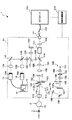
まず、この発明に係る光画像計測装置の実施形態の構成について図1〜図6を参照しながら説明する。ここで、図1は、この発明に係る光画像計測装置としての機能を有する眼底観察装置1の全体構成の一例を表している。図2は、眼底カメラユニット1A内の走査ユニット141の構成の一例を表している。図3は、OCTユニット150の構成の一例を表している。図4は、演算制御装置200のハードウェア構成の一例を表している。図5及び図6は、眼底観察装置1の制御系の構成の一例を表している。
[Device configuration]
First, the configuration of an embodiment of an optical image measurement device according to the present invention will be described with reference to FIGS. Here, FIG. 1 shows an example of the entire configuration of a fundus
[全体構成]
眼底観察装置1は、図1に示すように、眼底カメラユニット1A、OCTユニット150及び演算制御装置200を含んで構成される。眼底カメラユニット1Aは、眼底表面の2次元画像を撮影する従来の眼底カメラとほぼ同様の光学系を有している。OCTユニット150は、光画像計測装置として機能する光学系を格納している。演算制御装置200は、各種の演算処理や制御処理等を実行するコンピュータを具備している。
[overall structure]
As shown in FIG. 1, the fundus
OCTユニット150には、接続線152の一端が取り付けられている。接続線152の他端には、接続線152を眼底カメラユニット1Aに接続するコネクタ部151が取り付けられている。接続線152の内部には光ファイバが導通されている。このように、OCTユニット150と眼底カメラユニット1Aは、接続線152を介して光学的に接続されている。
One end of a
〔眼底カメラユニットの構成〕
眼底カメラユニット1Aは、光学的に取得されるデータ(撮像装置10、12により検出されるデータ)に基づいて被検眼の眼底の表面の2次元画像を撮影するために用いられる。ここで、眼底の表面の2次元画像とは、眼底の表面を撮影したカラー画像やモノクロ画像、更には蛍光画像(フルオレセイン蛍光画像、インドシアニングリーン蛍光画像等)などを表す。また、この2次元画像は、静止画像でも動画像でもよい。眼底カメラユニット1Aは、この発明の「撮影手段」の一例である。
[Configuration of fundus camera unit]
The
眼底カメラユニット1Aは、従来の眼底カメラと同様に、眼底Efを照明する照明光学系100と、この照明光の眼底反射光を撮像装置10に導く撮影光学系120とを備えている。
The
なお、詳細は後述するが、撮影光学系120における撮像装置10は、近赤外領域の波長を有する照明光を検出する。また、撮影光学系120には、可視領域の波長を有する照明光を検出する撮像装置12が別途設けられている。更に、撮影光学系120は、OCTユニット150からの信号光を眼底Efに導くとともに、眼底Efを経由した信号光をOCTユニット150に導くように作用する。
Although details will be described later, the
照明光学系100は、観察光源101、コンデンサレンズ102、撮影光源103、コンデンサレンズ104、エキサイタフィルタ105及び106、リング透光板107、ミラー108、LCD(Liquid Crystal Display)109、照明絞り110、リレーレンズ111、孔開きミラー112、対物レンズ113を含んで構成される。
The illumination
観察光源101は、たとえば約400nm〜700nmの範囲に含まれる可視領域の波長の照明光を出力する。また、撮影光源103は、たとえば約700nm〜800nmの範囲に含まれる近赤外領域の波長の照明光を出力する。撮影光源103から出力される近赤外光は、OCTユニット150で使用する光の波長よりも短く設定されている(後述)。
The observation
また、撮影光学系120は、対物レンズ113、孔開きミラー112(の孔部112a)、撮影絞り121、バリアフィルタ122及び123、変倍レンズ124、リレーレンズ125、撮影レンズ126、ダイクロイックミラー134、フィールドレンズ(視野レンズ)128、ハーフミラー135、リレーレンズ131、ダイクロイックミラー136、撮影レンズ133、撮像装置10(撮像素子10a)、反射ミラー137、撮影レンズ138、撮像装置12(撮像素子12a)、レンズ139及びLCD140を含んで構成される。
The photographing
更に、撮影光学系120には、ダイクロイックミラー134、ハーフミラー135、ダイクロイックミラー136、反射ミラー137、撮影レンズ138、レンズ139及びLCD140が設けられている。
Further, the photographing
ダイクロイックミラー134は、照明光学系100からの照明光の眼底反射光(約400nm〜800nmの範囲に含まれる波長を有する)を反射するとともに、OCTユニット150からの信号光LS(たとえば約800nm〜900nmの範囲に含まれる波長を有する;後述)を透過させるように構成されている。
The
また、ダイクロイックミラー136は、照明光学系100からの可視領域の波長を有する照明光(観察光源101から出力される波長約400nm〜700nmの可視光)を透過させるとともに、近赤外領域の波長を有する照明光(撮影光源103から出力される波長約700nm〜800nmの近赤外光)を反射するように構成されている。
Further, the
LCD140は、被検眼Eを固視させるための固視標(内部固視標)を表示する。LCD140からの光は、レンズ139により集光された後に、ハーフミラー135により反射され、フィールドレンズ128を経由してダイクロイックミラー136に反射される。更に、この光は、撮影レンズ126、リレーレンズ125、変倍レンズ124、孔開きミラー112(の孔部112a)、対物レンズ113等を経由して、被検眼Eに入射する。それにより、被検眼Eの眼底Efに内部固視標が投影される。
The
内部固視標を眼底Efに投影させるためのLCD140及びこれらの光学素子は、この発明の「呈示手段」の一例である。なお、呈示手段は、LCDに限定されるものではなく、たとえば他の表示装置を用いることもできるし、2次元的に配列された複数のLED(Light Emitted Diode)等の光源を用いることもできる。
The
内部固視標を用いて被検眼Eの固視位置を変更することができる。固視位置としては、たとえば、眼底中心がフレームの中心に配置された画像を取得するための固視位置(眼底中心用固視位置)、黄斑部(中心窩)がフレームの中心に配置された画像を取得するための固視位置(黄斑部用固視位置)、視神経乳頭がフレームの中心に配置された画像を取得するための固視位置(乳頭用固視位置)などがある。また、後述の操作部240Bを操作することにより任意の固視位置を適用することも可能である。 The fixation position of the eye E can be changed using the internal fixation target. As the fixation position, for example, a fixation position (fixation position for fundus center) for acquiring an image in which the fundus center is arranged at the center of the frame, and a macular portion (fovea) are arranged at the center of the frame. There are a fixation position (macular fixation position) for acquiring an image, a fixation position (papillary fixation position) for acquiring an image in which the optic disc is arranged at the center of the frame, and the like. It is also possible to apply an arbitrary fixation position by operating an operation unit 240B described later.
固視位置を変更するために、LCD140は、その表示面の異なる位置に内部固視標を表示する。この表示位置の制御は、後述の主制御部211が行う。また、内部固視標を眼底Efに投影する光学系を制御して固視位置を変更することも可能である。なお、複数の光源を含む呈示手段を用いる場合、点灯させる光源を変更することにより固視位置を変更することが可能である。
In order to change the fixation position, the
固視位置の指定は、たとえばオペレータが操作部240Bを操作して行う。また、たとえば経過観察を行う場合など固視位置が既知である場合には、自動的に固視位置を指定することが可能である。 The fixation position is designated by, for example, the operator operating the operation unit 240B. Further, when the fixation position is known, for example, when performing follow-up observation, it is possible to automatically specify the fixation position.
撮像素子10aは、テレビカメラ等の撮像装置10に内蔵されたCCD(Charge Coupled Devices)やCMOS(Complementary Metal Oxide Semiconductor)等の撮像素子であり、特に、近赤外領域の波長の光を検出する。つまり、撮像装置10は、近赤外光を検出する赤外線テレビカメラである。撮像装置10は、近赤外光を検出した結果として映像信号を出力する。
The
タッチパネルモニタ11は、この映像信号に基づいて、眼底Efの表面の2次元画像(眼底画像Ef′)を表示する。また、この映像信号は演算制御装置200に送られ、ディスプレイ(後述)に眼底画像が表示される。
The touch panel monitor 11 displays a two-dimensional image (fundus image Ef ′) of the surface of the fundus oculi Ef based on this video signal. The video signal is sent to the arithmetic and
なお、撮像装置10による眼底撮影時には、たとえば照明光学系100の撮影光源103から出力される近赤外領域の波長を有する照明光が用いられる。
At the time of fundus photographing by the
一方、撮像素子12aは、テレビカメラ等の撮像装置12に内蔵されたCCDやCMOS等の撮像素子であり、特に、可視領域の波長の光を検出する。つまり、撮像装置12は、可視光を検出するテレビカメラである。撮像装置12は、可視光を検出した結果として映像信号を出力する。
On the other hand, the
タッチパネルモニタ11は、この映像信号に基づいて、眼底Efの表面の2次元画像(眼底画像Ef′)を表示する。また、この映像信号は演算制御装置200に送られ、ディスプレイ(後述)に眼底画像が表示される。
The touch panel monitor 11 displays a two-dimensional image (fundus image Ef ′) of the surface of the fundus oculi Ef based on this video signal. The video signal is sent to the arithmetic and
なお、撮像装置12による眼底撮影時には、たとえば照明光学系100の観察光源101から出力される可視領域の波長を有する照明光が用いられる。
At the time of fundus photographing by the
眼底カメラユニット1Aには、走査ユニット141とレンズ142とが設けられている。走査ユニット141は、OCTユニット150から出力される光(信号光LS;後述)の眼底Efに対する照射位置を走査するための構成を具備する。走査ユニット141は、この発明の「走査手段」の一例である。
The
レンズ142は、OCTユニット150から接続線152を通じて導光された信号光LSを平行な光束にして走査ユニット141に入射させる。また、レンズ142は、走査ユニット141を経由してきた信号光LSの眼底反射光を集束させる。
The
図2に、走査ユニット141の構成の一例を示す。走査ユニット141は、ガルバノミラー141A、141Bと、反射ミラー141C、141Dとを含んで構成されている。
FIG. 2 shows an example of the configuration of the
ガルバノミラー141A、141Bは、それぞれ回動軸141a、141bを中心に回動可能に配設された反射ミラーである。各ガルバノミラー141A、141Bは、後述の駆動機構(図5に示すミラー駆動機構241、242)によって回動軸141a、141bを中心にそれぞれ回動される。それにより、各ガルバノミラー141A、141Bの反射面(信号光LSを反射する面)の向きが変更される。
Galvano mirrors 141A and 141B are reflection mirrors arranged so as to be rotatable about
回動軸141a、141bは、互いに直交して配設されている。図2においては、ガルバノミラー141Aの回動軸141aは、紙面に対して平行方向に配設されている。また、ガルバノミラー141Bの回動軸141bは、紙面に対して直交する方向に配設されている。
The rotating
すなわち、ガルバノミラー141Bは、図2中の両側矢印に示す方向に回動可能に構成され、ガルバノミラー141Aは、当該両側矢印に対して直交する方向に回動可能に構成されている。それにより、ガルバノミラー141A、141Bは、信号光LSの反射方向を互いに直交する方向に変更するようにそれぞれ作用する。図1、図2から分かるように、ガルバノミラー141Aを回動させると信号光LSはx方向に走査され、ガルバノミラー141Bを回動させると信号光LSはy方向に走査される。
That is, the galvano mirror 141B is configured to be rotatable in a direction indicated by a double-sided arrow in FIG. 2, and the
ガルバノミラー141A、141Bにより反射された信号光LSは、反射ミラー141C、141Dにより反射され、ガルバノミラー141Aに入射したときと同じ向きに進行するようになっている。
The signal light LS reflected by the galvanometer mirrors 141A and 141B is reflected by the reflection mirrors 141C and 141D and travels in the same direction as when incident on the
なお、接続線152の内部の光ファイバ152aの端面152bは、レンズ142に対峙して配設される。端面152bから出射された信号光LSは、レンズ142に向かってビーム径を拡大しつつ進行し、レンズ142によって平行な光束とされる。逆に、眼底Efを経由した信号光LSは、レンズ142により端面152bに向けて集束されて光ファイバ152aに入射する。
Note that the end surface 152 b of the
〔OCTユニットの構成〕
次に、OCTユニット150の構成について図3を参照しつつ説明する。OCTユニット150は、光学的に取得されるデータ(後述のCCD184により検出されるデータ)に基づいて眼底の断層画像を形成するための装置である。
[Configuration of OCT unit]
Next, the configuration of the
OCTユニット150は、信号光の光路を形成する眼底カメラユニット1A内の光学部材や、後述の画像形成部220とともに、この発明の「画像形成手段」の一例を構成する。
The
OCTユニット150は、従来の光画像計測装置とほぼ同様の光学系を備えている。すなわち、OCTユニット150は、低コヒーレンス光を参照光と信号光に分割し、被検眼を経由した信号光と参照物体を経由した参照光とを重畳させて干渉光を生成してこれを検出する。この検出結果(検出信号)は演算制御装置200に入力される。演算制御装置200は、この検出信号を解析して被検眼の断層画像を形成する。
The
低コヒーレンス光源160は、低コヒーレンス光L0を出力するスーパールミネセントダイオード(SLD:Super Luminescent Diode)や発光ダイオード(LED:Light Emitted Diode)等の広帯域光源により構成される。低コヒーレンス光L0は、たとえば、近赤外領域の波長の光を含み、かつ、数十マイクロメートル程度の時間的コヒーレンス長を有する光とされる。
The low coherence
低コヒーレンス光L0は、眼底カメラユニット1Aの照明光(波長約400nm〜800nm)よりも長い波長、たとえば約800nm〜900nmの範囲に含まれる波長を有する。
The low coherence light L0 has a wavelength longer than the illumination light (wavelength of about 400 nm to 800 nm) of the
低コヒーレンス光源160から出力された低コヒーレンス光L0は、光ファイバ161を通じて光カプラ162に導かれる。光ファイバ161は、たとえばシングルモードファイバないしはPMファイバ(Polarization maintaining fiber;偏波面保持ファイバ)等によって構成されている。光カプラ162は、低コヒーレンス光L0を参照光LRと信号光LSとに分割する。
The low coherence light L0 output from the low coherence
なお、光カプラ162は、光を分割する手段(スプリッタ;splitter)、及び、光を重畳する手段(カプラ;coupler)の双方として作用するものであるが、ここでは慣用的に「光カプラ」と称することにする。
The
光カプラ162により生成された参照光LRは、シングルモードファイバ等からなる光ファイバ163により導光されてファイバ端面から出射される。更に、参照光LRは、コリメータレンズ171により平行光束とされた後に、ガラスブロック172及び濃度フィルタ173を経由し、参照ミラー174により反射される。参照ミラー174は、この発明の「参照物体」の例である。
The reference light LR generated by the
参照ミラー174により反射された参照光LRは、再び濃度フィルタ173及びガラスブロック172を経由し、コリメータレンズ171によって光ファイバ163のファイバ端面に集光され、光ファイバ163を通じて光カプラ162に導かれる。
The reference light LR reflected by the
ここで、ガラスブロック172と濃度フィルタ173は、参照光LRと信号光LSの光路長(光学距離)を合わせるための遅延手段として、また参照光LRと信号光LSの分散特性を合わせるための分散補償手段として作用している。
Here, the
また、濃度フィルタ173は、参照光の光量を減少させる減光フィルタとしても作用し、たとえば回転型のND(Neutral Density)フィルタによって構成される。濃度フィルタ173は、モータ等の駆動装置を含んで構成される駆動機構(後述の濃度フィルタ駆動機構244;図5参照)によって回転駆動されることで、参照光LRの光量の減少量を変更させるように作用する。それにより、干渉光LCの生成に寄与する参照光LRの光量を変更させることができる。
Further, the
また、参照ミラー174は、参照光LRの進行方向(図3に示す両側矢印方向)に移動されるようになっている。それにより、被検眼Eの眼軸長やワーキングディスタンス(対物レンズ113と被検眼Eとの距離)などに応じた参照光LRの光路長を確保できる。また、参照ミラー174を移動させることにより、眼底Efの任意の深度位置の画像を取得することが可能である。なお、参照ミラー174は、モータ等の駆動装置を含んで構成される駆動機構(後述の参照ミラー駆動機構243;図5参照)によって移動される。
Further, the
一方、光カプラ162により生成された信号光LSは、シングルモードファイバ等からなる光ファイバ164により接続線152の端部まで導光される。接続線152の内部には光ファイバ152aが導通されている。なお、光ファイバ164と光ファイバ152aは、単一の光ファイバから形成されていてもよいし、各々の端面同士を接合するなどして一体的に形成されていてもよい。いずれにしても、光ファイバ164、152aは、眼底カメラユニット1AとOCTユニット150との間で、信号光LSを伝送可能に構成されていれば十分である。
On the other hand, the signal light LS generated by the
信号光LSは、接続線152内部を導光されて眼底カメラユニット1Aに案内される。更に、信号光LSは、レンズ142、走査ユニット141、ダイクロイックミラー134、撮影レンズ126、リレーレンズ125、変倍レンズ124、撮影絞り121、孔開きミラー112の孔部112a、対物レンズ113を経由して被検眼Eに照射される。なお、信号光LSを被検眼Eに照射させるときには、バリアフィルタ122、123は、それぞれ事前に光路から退避される。
The signal light LS is guided through the
被検眼Eに入射した信号光LSは、眼底Ef上にて結像し反射される。このとき、信号光LSは、眼底Efの表面で反射されるだけでなく、眼底Efの深部領域にも到達して屈折率境界において散乱される。したがって、眼底Efを経由した信号光LSは、眼底Efの表面形態を反映する情報と、眼底Efの深層組織の屈折率境界における後方散乱の状態を反映する情報とを含んでいる。この光を単に「信号光LSの眼底反射光」と呼ぶことがある。 The signal light LS incident on the eye E is imaged and reflected on the fundus oculi Ef. At this time, the signal light LS is not only reflected by the surface of the fundus oculi Ef, but also reaches the deep region of the fundus oculi Ef and is scattered at the refractive index boundary. Therefore, the signal light LS passing through the fundus oculi Ef includes information reflecting the surface form of the fundus oculi Ef and information reflecting the state of backscattering at the refractive index boundary of the deep tissue of the fundus oculi Ef. This light may be simply referred to as “fundus reflected light of the signal light LS”.
信号光LSの眼底反射光は、眼底カメラユニット1A内の上記経路を逆向きに進行して光ファイバ152aの端面152bに集光され、光ファイバ152を通じてOCTユニット150に入射し、光ファイバ164を通じて光カプラ162に戻ってくる。
The fundus reflection light of the signal light LS travels in the reverse direction in the
光カプラ162は、被検眼Eを経由して戻ってきた信号光LSと、参照ミラー174にて反射された参照光LRとを重畳して干渉光LCを生成する。生成された干渉光LCは、シングルモードファイバ等からなる光ファイバ165を通じてスペクトロメータ180に導かれる。
The
なお、この実施形態ではマイケルソン型の干渉計を採用しているが、たとえばマッハツェンダー型など任意のタイプの干渉計を適宜に採用することが可能である。 In this embodiment, a Michelson interferometer is used. However, for example, any type of interferometer such as a Mach-Zehnder type can be appropriately used.
スペクトロメータ(分光計)180は、コリメータレンズ181、回折格子182、結像レンズ183、CCD184を含んで構成される。回折格子182は、光を透過させる透過型の回折格子であってもよいし、光を反射する反射型の回折格子であってもよい。また、CCD184に代えて、CMOS等の他の光検出素子を用いることも可能である。
The spectrometer (spectrometer) 180 includes a
スペクトロメータ180に入射した干渉光LCは、コリメータレンズ181により平行光束とされ、回折格子182によって分光(スペクトル分解)される。分光された干渉光LCは、結像レンズ183によってCCD184の撮像面上に結像される。CCD184は、分光された干渉光LCの各スペクトルを検出して電気的な信号に変換し、この検出信号を演算制御装置200に出力する。
The interference light LC incident on the
〔演算制御装置の構成〕
次に、演算制御装置200の構成について説明する。演算制御装置200は、OCTユニット150のCCD184から入力される検出信号を解析して、眼底Efの断層画像を形成する。このときの解析手法は、従来のフーリエドメインOCTの手法と同様である。
[Configuration of arithmetic control unit]
Next, the configuration of the arithmetic and
また、演算制御装置200は、眼底カメラユニット1Aの撮像装置10、12から出力される映像信号に基づいて眼底Efの表面の形態を示す2次元画像を形成する。
Further, the arithmetic and
更に、演算制御装置200は、眼底カメラユニット1A及びOCTユニット150の各部を制御する。
Further, the arithmetic and
眼底カメラユニット1Aの制御として、演算制御装置200は、観察光源101や撮影光源103による照明光の出力制御、エキサイタフィルタ105、106やバリアフィルタ122、123の光路上への挿入/退避動作の制御、LCD140等の表示装置の動作制御、照明絞り110の移動制御(絞り値の制御)、撮影絞り121の絞り値の制御、変倍レンズ124の移動制御(倍率の制御)などを行う。更に、演算制御装置200は、ガルバノミラー141A、141Bの動作制御を行う。
As control of the
また、OCTユニット150の制御として、演算制御装置200は、低コヒーレンス光源160による低コヒーレンス光L0の出力制御、参照ミラー174の移動制御、濃度フィルタ173の回転動作(参照光LRの光量の減少量の変更動作)の制御、CCD184の蓄積時間の制御などを行う。
Further, as the control of the
このような演算制御装置200のハードウェア構成について図4を参照しつつ説明する。
The hardware configuration of such an
演算制御装置200は、従来のコンピュータと同様のハードウェア構成を備えている。具体的には、演算制御装置200は、マイクロプロセッサ201、RAM202、ROM203、ハードディスクドライブ(HDD)204、キーボード205、マウス206、ディスプレイ207、画像形成ボード208及び通信インターフェイス(I/F)209を含んで構成される。これら各部は、バス200aにより接続されている。
The arithmetic and
マイクロプロセッサ201は、CPU(Central Processing Unit)やMPU(Micro Processing Unit)等を含んで構成される。マイクロプロセッサ201は、ハードディスクドライブ204に格納された制御プログラム204aをRAM202上に展開することで、この実施形態に特徴的な動作を実行する。
The
また、マイクロプロセッサ201は、前述した装置各部の制御や、各種の演算処理などを実行する。また、マイクロプロセッサ201は、キーボード205やマウス206からの操作信号を受け、その操作内容に応じて装置各部を制御する。更に、マイクロプロセッサ201は、ディスプレイ207による表示処理の制御や、通信インターフェイス209によるデータや信号の送受信処理の制御などを行う。
Further, the
キーボード205、マウス206及びディスプレイ207は、眼底観察装置1のユーザインターフェイスとして使用される。キーボード205は、たとえば文字や数字等をタイピング入力するためのデバイスとして用いられる。マウス206は、ディスプレイ207の表示画面に対する各種入力操作を行うためのデバイスとして用いられる。
The
また、ディスプレイ207は、たとえばLCDやCRT(Cathode Ray Tube)ディスプレイ等の表示デバイスであり、眼底観察装置1により形成された眼底Efの画像などの各種の画像を表示したり、操作画面や設定画面などの各種の画面を表示したりする。
The
なお、眼底観察装置1のユーザインターフェイスは、このような構成に限定されるものではなく、たとえばトラックボール、ジョイスティック、タッチパネル式のLCD、眼科検査用のコントロールパネルなどを含んでいてもよい。ユーザインターフェイスとしては、情報を表示出力する機能と、情報を入力したり装置の操作を行ったりする機能とを具備する任意の構成を採用できる。
The user interface of the fundus
画像形成ボード208は、眼底Efの画像(画像データ)を形成する処理を行う専用の電子回路である。画像形成ボード208には、眼底画像形成ボード208aとOCT画像形成ボード208bとが設けられている。
The
眼底画像形成ボード208aは、撮像装置10や撮像装置12からの映像信号に基づいて眼底画像の画像データを形成する専用の電子回路である。
The fundus
また、OCT画像形成ボード208bは、OCTユニット150のCCD184からの検出信号に基づいて眼底Efの断層画像の画像データを形成する専用の電子回路である。
The OCT
このような画像形成ボード208を設けることにより、眼底画像や断層画像を形成する処理の処理速度を向上させることができる。
By providing such an
通信インターフェイス209は、マイクロプロセッサ201からの制御信号を、眼底カメラユニット1AやOCTユニット150に送信する。また、通信インターフェイス209は、撮像装置10、12からの映像信号や、OCTユニット150のCCD184からの検出信号を受信して、画像形成ボード208に入力する。このとき、通信インターフェイス209は、撮像装置10、12からの映像信号を眼底画像形成ボード208aに入力し、CCD184からの検出信号をOCT画像形成ボード208bに入力するようになっている。
The
また、演算制御装置200がLAN(Local Area Network)やインターネット等の通信回線に接続されている場合には、LANカード等のネットワークアダプタやモデム等の通信機器を通信インターフェイス209に具備させ、この通信回線を介してデータ通信を行えるように構成できる。この場合、制御プログラム204aを格納するサーバを通信回線上に設置するとともに、演算制御装置200を当該サーバのクライアント端末として構成することにより、眼底観察装置1を動作させることができる。
When the arithmetic and
[制御系の構成]
次に、眼底観察装置1の制御系の構成について図5及び図6を参照しつつ説明する。
[Control system configuration]
Next, the configuration of the control system of the fundus
〔制御部〕
眼底観察装置1の制御系は、演算制御装置200の制御部210を中心に構成される。制御部210は、マイクロプロセッサ201、RAM202、ROM203、ハードディスクドライブ204(制御プログラム204a)、通信インターフェイス209等を含んで構成される。
(Control part)
The control system of the fundus
制御部210は、制御プログラム204aに基づいて動作するマイクロプロセッサ201により前述の制御を行う。制御部210には、主制御部211と記憶部212が設けられている。
The
(主制御部)
主制御部211は、ミラー駆動機構241、242を制御してガルバノミラー141A、141Bの位置を制御し、それにより、眼底Efに対する信号光LSの照射位置を走査させる。また、主制御部211は、LCD140を制御して内部固視標を表示させる。特に、主制御部211は、ミラー駆動機構241、242とLCDとを同時に制御して、被検眼Eに内部固視標を呈示させるとともに信号光LSを走査させる。主制御部211は、この発明の「制御手段」の一例である。
(Main control unit)
The
また、主制御部211は、低コヒーレンス光源160の点灯/消灯の制御、CCD184の制御、濃度フィルタ173を回転させるための濃度フィルタ駆動機構244の制御、参照光LRの進行方向に参照ミラー174を移動させるための参照ミラー駆動機構243の制御などを実行する。
Further, the
また、主制御部211は、眼底観察装置1により撮影される2種類の画像、すなわち眼底画像Ef′と断層画像とを、ユーザインターフェイス(UI)240の表示部240Aに表示させる。これらの画像は、それぞれ別々に表示部240Aにさせることもできるし、これらを並べて表示させることもできる。
In addition, the
(記憶部)
記憶部212は、眼底画像Ef′の画像データ、眼底Efの断層画像や3次元画像等のOCT画像の画像データなどが記憶される。また、記憶部212には、検査に関するデータや患者に関するデータなど、各種のデータが記憶される。記憶部212に対するデータの書き込み処理や、記憶部212からのデータの読み出し処理は、主制御部211が実行する。
(Memory part)
The
〔画像形成部〕
画像形成部220は、撮像装置10、12からの映像信号に基づいて眼底画像Ef′の画像データを形成する。また、画像形成部220は、OCTユニット150のCCD184からの検出信号に基づいて眼底Efの断層画像の画像データを形成する。
(Image forming part)
The
画像形成部220は、画像形成ボード208や通信インターフェイス209等を含んで構成される。なお、この明細書では、「画像」と、それに対応する「画像データ」とを同一視することがある。
The
〔画像処理部〕
画像処理部230は、画像形成部220により形成された画像の画像データに対して各種の画像処理や解析処理を施す。たとえば、画像処理部230は、画像の輝度補正や分散補正等の各種補正処理などを実行する。
(Image processing unit)
The
また、画像処理部230は、画像形成部220により形成された断層画像に対し、断層画像間の画素を補間する補間処理等を施すことで、眼底Efの3次元画像の画像データを形成する。
Further, the
なお、3次元画像の画像データとは、3次元的に配列された複数のボクセルのそれぞれに画素値を付与して成る画像データである。この画像データは、ボリュームデータ或いはボクセルデータなどと呼ばれる。ボリュームデータに基づく画像を表示させる場合、画像処理部230は、このボリュームデータに対してレンダリング処理(ボリュームレンダリングやMIP(Maximum Intensity Projection:最大値投影)など)を施して、特定の視線方向から見たときの擬似的な3次元画像の画像データを形成する。ディスプレイ207等の表示デバイスには、この画像データに基づく擬似的な3次元画像が表示される。
Note that the image data of a three-dimensional image is image data obtained by assigning a pixel value to each of a plurality of voxels arranged three-dimensionally. This image data is called volume data or voxel data. When displaying an image based on volume data, the
また、画像処理部230は、複数の断層画像のスタックデータを形成することも可能である。スタックデータは、複数の走査線に沿って得られた複数の断層画像を、走査線の位置関係に基づいて配列させることにより得られる画像データである。
The
画像処理部230には、固視状態判定部231と画像位置補正部232が設けられている。
The
(固視状態判定部)
固視状態判定部231は、眼底Efの画像に基づいて被検眼Eの固視状態の適否を判定する。眼底Efの画像としては、眼底Efの表面の2次元画像や眼底の断層画像などがある。この画像は、静止画像でも動画像でもよい。
(Fixation state determination unit)
The fixation
この画像が動画像である場合、固視状態判定部231は、この動画像を形成するフレーム毎に固視状態の適否を判定する。ここで、この動画像を形成する全てのフレームについてそれぞれ固視状態の適否を判定してもよいし、全てのフレームから選択されたフレームについてのみ固視状態の適否を判定してもよい。後者の例としては、所定のフレーム数毎に固視状態の適否を判定する方法がある。
When this image is a moving image, the fixation
固視状態判定部231の動作の具体例を説明する。固視状態判定部231は、眼底Efの画像を解析して画像中における眼底Efの特徴部位の画像位置を特定し、この画像位置に基づいて固視状態の適否を判定する。このとき、画像の全体又は一部における輝度分布に基づいて特徴部位の画像位置を特定することにより、処理に掛かる時間の短縮を図ることができる。
A specific example of the operation of the fixation
まず、眼底の特徴部位の画像位置を特定する処理について説明する。眼底の表面の2次元画像における特徴部位としては、黄斑部、視神経乳頭、血管の分岐点などがある。黄斑部の画像位置は、たとえば、周囲よりも暗い(輝度が低い)略円形の領域を2次元画像から抽出することで特定できる。視神経乳頭の画像位置は、たとえば、周囲よりも明るい(輝度が高い)略円形の領域を2次元画像から抽出することで特定できる。また、画像中で最も明るい略円形の領域を抽出しても視神経乳頭の画像位置を特定できる。血管の分岐点の画像位置は、たとえば、血管に相当する画像領域を2次元画像から抽出し、この抽出領域のワイヤモデルを生成し、このワイヤモデルの分岐点を求めることで特定できる。これらの処理は、2次元画像の画素値を解析することで実現できる。 First, a process for specifying the image position of the characteristic part of the fundus will be described. Examples of the characteristic site in the two-dimensional image of the fundus surface include the macula, the optic nerve head, and a blood vessel branch point. The image position of the macula can be identified by extracting a substantially circular area darker (lower brightness) than the surroundings from the two-dimensional image, for example. The image position of the optic nerve head can be specified by, for example, extracting a substantially circular area brighter (higher brightness) than the surroundings from the two-dimensional image. In addition, the image position of the optic nerve head can be specified by extracting the brightest substantially circular region in the image. The image position of the branch point of the blood vessel can be specified by, for example, extracting an image region corresponding to the blood vessel from the two-dimensional image, generating a wire model of the extracted region, and obtaining the branch point of the wire model. These processes can be realized by analyzing the pixel values of the two-dimensional image.
また、断層画像における特徴部位としては、黄斑部、視神経乳頭、眼底の層、血管などがある。黄斑部の画像位置は、たとえば、眼底表面に相当する領域を断層画像から抽出し、この領域における窪みの位置として特定できる。視神経乳頭の画像位置は、たとえば、眼底表面に相当する領域を断層画像から特定し、この領域における大きな窪みの位置として特定できる。眼底の層の画像位置は、たとえば、目的の層に相当する領域を断層画像から抽出することで特定できる。なお、眼底の層としては、網膜、脈絡膜、強膜等がある。更に、網膜には、内境界膜、視神経繊維層、神経節細胞層、内網状層、内顆粒層、外網状層、外顆粒層、外境界膜、視細胞層、網膜色素上皮層等がある。血管の画像位置は、たとえば、血管に相当する断層画像中の領域として特定できる。なお、断層画像においては、血管より深い部分の画像が明瞭に描写されないことがあるので、このような不明瞭な領域を特定することにより血管に相当する領域を特定できる。 In addition, as characteristic portions in the tomographic image, there are a macular portion, an optic nerve head, a fundus layer, a blood vessel, and the like. The image position of the macular portion can be specified as, for example, a region corresponding to the fundus surface is extracted from the tomographic image and the position of the depression in this region. The image position of the optic nerve head can be specified as, for example, a region corresponding to the fundus surface from a tomographic image and a position of a large depression in this region. The image position of the fundus layer can be identified by, for example, extracting a region corresponding to the target layer from the tomographic image. The fundus layer includes the retina, choroid, sclera and the like. Furthermore, the retina has an inner boundary membrane, optic nerve fiber layer, ganglion cell layer, inner reticular layer, inner granule layer, outer reticular layer, outer granule layer, outer boundary membrane, photoreceptor layer, retinal pigment epithelium layer, etc. . The image position of the blood vessel can be specified as an area in the tomographic image corresponding to the blood vessel, for example. Note that in a tomographic image, an image of a portion deeper than a blood vessel may not be clearly depicted, and thus a region corresponding to a blood vessel can be specified by specifying such an unclear region.
次に、固視状態の適否を判定する処理について説明する。まず、眼底Efの画像のフレーム内の所定位置を基準位置に設定する。基準位置としては、たとえばフレームの中心位置などを適用できる。固視状態判定部231は、基準位置に対する特徴部位の画像位置の変位を求める。この変位は、たとえば、基準位置の座標値と特徴部位の画像位置の座標値とに基づいて三平方の定理により算出できる。また、各座標方向の変位成分として変位を求めてもよい。また、基準位置から特徴部位の画像位置までのピクセル数として変位を求めてもよい。
Next, a process for determining the suitability of the fixation state will be described. First, a predetermined position in the frame of the image of the fundus oculi Ef is set as a reference position. As the reference position, for example, the center position of the frame can be applied. The fixation
固視状態判定部231は、この変位(の大きさ)を所定閾値と比較する。この閾値はあらかじめ設定される。変位が閾値以下である場合、固視状態判定部231は、適正な固視状態、つまり当該画像の取得時に固視が適正になされていたと判定する。一方、変位が閾値を超える場合、固視状態判定部231は、不適正な固視状態、つまり当該画像の取得時に固視が適正になされていなかったと判定する。不適正な固視状態の要因としては、信号光LSの走査の軌跡を被検眼Eが追従したことなどがある。
The fixation
判定処理の別の例を説明する。まず、画像のフレーム内の所定領域を基準領域に設定する。基準領域は、たとえばフレーム中央の所定サイズの領域として設定される。このサイズは、たとえば上記の閾値程度に設定できる。 Another example of the determination process will be described. First, a predetermined area in an image frame is set as a reference area. The reference area is set as an area of a predetermined size at the center of the frame, for example. This size can be set, for example, to the above threshold value.
固視状態判定部231は、特徴部位の画像位置が基準領域に含まれるか否か判断する。この処理は双方の画素の位置を比較することにより実行できる。特徴部位の画像位置が基準位置に含まれると判断された場合、固視状態判定部231は、適正な固視状態と判定する。一方、含まれないと判断された場合、固視状態判定部231は、不適正な固視状態と判定する。
The fixation
このように動作する固視状態判定部231は、前述の撮影手段や画像形成手段とともに、この発明の「判定手段」の一例を構成する。
The fixation
(画像位置補正部)
画像位置補正部232は、固視状態判定部231が眼底表面の2次元画像に基づいて上記変位を算出した場合に動作する。画像位置補正部232は、この変位に基づいて眼底Efの断層画像の位置を補正する。この処理は、当該変位を打ち消すように断層画像のxy方向の位置(眼底表面における位置)を変更することにより行う。たとえば、変位が(Δx、Δy)である場合、画像位置補正部232は、断層画像のx座標値を−Δxだけ変更し、y座標値を−Δyだけ変更する。
(Image position correction unit)
The image
以上のように動作する画像処理部230は、マイクロプロセッサ201、RAM202、ROM203、ハードディスクドライブ204(制御プログラム204a)等を含んで構成されている。
The
このように動作する画像位置補正部232は、この発明の「補正手段」の一例である。
The image
(ユーザインターフェイス)
ユーザインターフェイス(User Interface;UI)240には、表示部240Aと操作部240Bが設けられている。表示部240Aは、ディスプレイ207等の表示デバイスにより構成される。また、操作部240Bは、キーボード205やマウス206などの入力デバイスや操作デバイスにより構成される。
(User interface)
A user interface (UI) 240 is provided with a
[信号光の走査及び画像処理について]
信号光LSの走査は、前述のように、走査ユニット141のガルバノミラー141A、141Bの反射面の向きを変更することで行う。制御部210は、ミラー駆動機構241、242をそれぞれ制御することで、ガルバノミラー141A、141Bの反射面の向きをそれぞれ変更し、それにより信号光LSを眼底Ef上において走査する。
[Signal light scanning and image processing]
As described above, the scanning with the signal light LS is performed by changing the direction of the reflecting surfaces of the galvanometer mirrors 141A and 141B of the
ガルバノミラー141Aの反射面の向きが変更されると、信号光LSは、眼底Ef上において水平方向(図1のx方向)に走査される。一方、ガルバノミラー141Aの反射面の向きが変更されると、信号光LSは、眼底Ef上において垂直方向(図1のy方向)に走査される。また、ガルバノミラー141A、141Bの双方の反射面の向きを同時に変更させることにより、x方向とy方向とを合成した方向に信号光LSを走査することができる。すなわち、これら2つのガルバノミラー141A、141Bを制御することにより、xy平面上の任意の方向に信号光LSを走査することができる。
When the direction of the reflecting surface of the
図7は、眼底Efの画像を形成するための信号光LSの走査態様の一例を表している。図7(A)は、信号光LSが被検眼Eに入射する方向から眼底Efを見た(つまり図1の−z方向から+z方向を見た)ときの、信号光LSの走査態様の一例を表す。また、図7(B)は、眼底Ef上の各走査線における走査点(画像計測を行う位置)の配列態様の一例を表す。 FIG. 7 shows an example of a scanning mode of the signal light LS for forming an image of the fundus oculi Ef. FIG. 7A shows an example of a scanning mode of the signal light LS when the fundus oculi Ef is viewed from the direction in which the signal light LS enters the eye E (that is, when viewed from the −z direction to the + z direction in FIG. 1). Represents. FIG. 7B illustrates an example of an arrangement mode of scanning points (positions where image measurement is performed) on each scanning line on the fundus oculi Ef.
図7(A)に示すように、信号光LSは、あらかじめ設定された矩形の走査領域R内を走査される。走査領域R内には、x方向に複数(m本)の走査線R1〜Rmが設定されている。各走査線Ri(i=1〜m)に沿って信号光LSが走査されるときに、干渉光LCの検出信号が生成されるようになっている。 As shown in FIG. 7A, the signal light LS is scanned in a rectangular scanning region R set in advance. In the scanning region R, a plurality (m) of scanning lines R1 to Rm are set in the x direction. When the signal light LS is scanned along each scanning line Ri (i = 1 to m), a detection signal of the interference light LC is generated.
各走査線Riの方向を「主走査方向」と呼び、それに直交する方向を「副走査方向」と呼ぶ。したがって、信号光LSの主走査方向への走査は、ガルバノミラー141Aの反射面の向きを変更することにより実行される。また、副走査方向への走査は、ガルバノミラー141Bの反射面の向きを変更することによって実行される。
The direction of each scanning line Ri is referred to as the “main scanning direction”, and the direction orthogonal thereto is referred to as the “sub-scanning direction”. Therefore, scanning of the signal light LS in the main scanning direction is executed by changing the direction of the reflecting surface of the
各走査線Ri上には、図7(B)に示すように、複数(n個)の走査点Ri1〜Rinがあらかじめ設定されている。 On each scanning line Ri, as shown in FIG. 7B, a plurality (n) of scanning points Ri1 to Rin are set in advance.
図7に示す走査を実行するために、制御部210は、まず、ガルバノミラー141A、141Bを制御し、眼底Efに対する信号光LSの入射目標を第1の走査線R1上の走査開始位置RS(走査点R11)に設定する。続いて、制御部210は、低コヒーレンス光源160を制御し、低コヒーレンス光L0をフラッシュ発光させて、走査開始位置RSに信号光LSを入射させる。CCD184は、この信号光LSの走査開始位置RSにおける眼底反射光に基づく干渉光LCを受光し、検出信号を制御部210に出力する。
In order to execute the scan illustrated in FIG. 7, the
次に、制御部210は、ガルバノミラー141Aを制御して、信号光LSを主走査方向に走査して、その入射目標を走査点R12に設定し、低コヒーレンス光L0をフラッシュ発光させて走査点R12に信号光LSを入射させる。CCD184は、この信号光LSの走査点R12における眼底反射光に基づく干渉光LCを受光し、検出信号を制御部210に出力する。
Next, the
制御部210は、同様にして、信号光LSの入射目標を走査点R13、R14、・・・、R1(n−1)、R1nと順次移動させつつ、各走査点において低コヒーレンス光L0をフラッシュ発光させることにより、各走査点ごとの干渉光LCに対応してCCD184から出力される検出信号を取得する。
Similarly, the
第1の走査線R1の最後の走査点R1nにおける計測が終了したら、制御部210は、ガルバノミラー141A、141Bを同時に制御して、信号光LSの入射目標を、線換え走査rに沿って第2の走査線R2の最初の走査点R21まで移動させる。そして、この第2の走査線R2の各走査点R2j(j=1〜n)について前述の計測を行うことで、各走査点R2jに対応する検出信号をそれぞれ取得する。
When the measurement at the last scanning point R1n of the first scanning line R1 is completed, the
同様に、第3の走査線R3、・・・・、第m−1の走査線R(m−1)、第mの走査線Rmのそれぞれについて計測を行い、各走査点に対応する検出信号を取得する。なお、走査線Rm上の符号REは、走査点Rmnに対応する走査終了位置である。 Similarly, measurement is performed for each of the third scanning line R3,..., The m−1th scanning line R (m−1), and the mth scanning line Rm, and a detection signal corresponding to each scanning point. To get. Note that the symbol RE on the scanning line Rm is a scanning end position corresponding to the scanning point Rmn.
それにより、制御部210は、走査領域R内のm×n個の走査点Rij(i=1〜m、j=1〜n)に対応するm×n個の検出信号を取得する。以下、走査点Rijに対応する検出信号をDijと表すことがある。
Thereby, the
以上のような走査点の移動と低コヒーレンス光L0の出力との連動制御は、たとえば、ミラー駆動機構241、242に対する制御信号の送信タイミングと、低コヒーレンス光源160に対する制御信号の送信タイミングとを互いに同期させることによって実現できる。
For example, the linked control of the movement of the scanning point and the output of the low-coherence light L0 is performed by setting the control signal transmission timing to the
制御部210は、上述のように各ガルバノミラー141A、141Bを動作させるときに、その動作内容を示す情報として走査線Riの位置や走査点Rijの位置(xy座標系における座標)を記憶するようになっている。この記憶内容(走査位置情報)は、従来と同様に画像形成処理などにおいて用いられる。
When the galvanometer mirrors 141A and 141B are operated as described above, the
次に、図7に示す信号光LSの走査を実施した場合における画像処理の例を説明する。 Next, an example of image processing when the signal light LS shown in FIG. 7 is scanned will be described.
画像形成部220は、各走査線Ri(主走査方向)に沿った眼底Efの断層画像を形成する。また、画像処理部230は、画像形成部220により形成された断層画像に基づいて眼底Efの3次元画像を形成する。
The
画像形成部220による断層画像の形成処理は、従来と同様に、2段階の演算処理を含んで構成される。第1段階の演算処理においては、各走査点Rijに対応する検出信号Dijに基づいて、その走査点Rijにおける眼底Efの深度方向(図1に示すz方向)の画像を形成する。
The tomographic image forming process by the
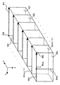
図8は、画像形成部220により形成される断層画像の態様を表している。第2段階の演算処理においては、各走査線Riについて、その上のn個の走査点Ri1〜Rinにおける深度方向の画像に基づき、この走査線Riに沿った眼底Efの断層画像Giを形成する。このとき、画像形成部220は、各走査点Ri1〜Rinの位置情報(前述の走査位置情報)を参照して各走査点Ri1〜Rinの配列及び間隔を決定して、この走査線Riを形成するようになっている。以上の処理により、副走査方向(y方向)の異なる位置におけるm個の断層画像G1〜Gmが得られる。
FIG. 8 illustrates an aspect of a tomographic image formed by the
次に、画像処理部230による眼底Efの3次元画像の形成処理について説明する。眼底Efの3次元画像は、上記の演算処理により得られたm個の断層画像に基づいて形成される。画像処理部230は、隣接する断層画像Gi、G(i+1)の間の画像を補間する公知の補間処理を行うなどして、眼底Efの3次元画像を形成する。
Next, a process for forming a three-dimensional image of the fundus oculi Ef by the
このとき、画像処理部230は、各走査線Riの位置情報を参照して各走査線Riの配列及び間隔を決定して、この3次元画像を形成するようになっている。この3次元画像には、各走査点Rijの位置情報(前述の走査位置情報)と、深度方向の画像におけるz座標とに基づいて、3次元座標系(x、y、z)が設定される。
At this time, the
また、画像処理部230は、この3次元画像に基づいて、主走査方向(x方向)以外の任意方向の断面における眼底Efの断層画像を形成することができる。断面が指定されると、画像処理部230は、この指定断面上の各走査点(及び/又は補間された深度方向の画像)の位置を特定し、各特定位置における深度方向の画像(及び/又は補間された深度方向の画像)を3次元画像から抽出し、抽出された複数の深度方向の画像を配列させることにより当該指定断面における眼底Efの断層画像を形成する。
Further, the
なお、図8に示す画像Gmjは、走査線Rm上の走査点Rmjにおける深度方向(z方向)の画像を表している。同様に、前述の第1段階の演算処理において形成される、各走査線Ri上の各走査点Rijにおける深度方向の画像を、「画像Gij」と表す。 Note that an image Gmj shown in FIG. 8 represents an image in the depth direction (z direction) at the scanning point Rmj on the scanning line Rm. Similarly, an image in the depth direction at each scanning point Rij on each scanning line Ri, which is formed in the above-described first stage arithmetic processing, is represented as “image Gij”.
[使用形態]
眼底観察装置1の使用形態について説明する。この使用形態では、OCT画像を取得する前に固視の練習を行う使用形態と、固視状態の適否を判定する使用形態とを説明する。
[Usage form]
A usage pattern of the fundus
〔第1の使用形態〕
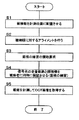
OCT画像を取得する前に固視の練習を行う使用形態について説明する。図9に示すフローチャートは、この使用形態の一例を表している。
[First usage pattern]
A usage pattern in which fixation practice is performed before an OCT image is acquired will be described. The flowchart shown in FIG. 9 represents an example of this usage pattern.
まず、被検眼Eを所定の計測位置(対物レンズ113に対峙する位置)に配置させる(S1)。眼底観察装置1には、従来の眼底カメラと同様に、被検眼Eの位置を固定させるための顎受けや額当てが設けられている(図示せず)。
First, the eye E is placed at a predetermined measurement position (a position facing the objective lens 113) (S1). The fundus
次に、被検眼Eに対する装置光学系のアライメントを行う(S2)。アライメントは、従来の眼底カメラと同様に、アライメント輝点やスケールを用いて実施される。アライメントが完了したら、オペレータは、操作部240Bを操作して固視の練習の開始を要求する(S3)。 Next, the apparatus optical system is aligned with the eye E (S2). Alignment is performed using alignment bright spots and scales in the same manner as a conventional fundus camera. When the alignment is completed, the operator operates the operation unit 240B to request the start of fixation fixation practice (S3).
この要求を受けた主制御部211は、低コヒーレンス光源160及びミラー駆動機構241、242を制御し、被検眼Eに対して信号光LSを走査させて被検者に走査の軌跡を視認させるとともに、LCD140を制御し、固視標を表示させて被検者に固視標を視認させる。それにより、被検者は、信号光LSの走査の軌跡と固視標の双方を同時に視認する(S4)。
Upon receiving this request, the
たとえば、図7に示す走査を実施する場合、被検者は、固視標とともに、走査の軌跡として上下方向(y方向)に移動する赤色の線(x方向に延びる線)を視認する。オペレータ(検者)は、被検者に対して固視標を凝視するようアドバイスする。このような固視標を凝視する練習は、走査の軌跡が移動する状況において固視標を確実に凝視できるまで行うことが望ましい。 For example, when the scanning shown in FIG. 7 is performed, the subject visually recognizes a red line (a line extending in the x direction) that moves in the vertical direction (y direction) as a scanning trajectory together with the fixation target. The operator (examiner) advises the subject to stare at the fixation target. It is desirable to practice staring at such a fixation target until the fixation target can be surely stared in a situation where the scanning trajectory moves.
練習が終了したら、眼底Efを計測してOCT画像を取得する(S5)。なお、計測時に被検眼Eが適正に固視されていない場合には、固視の練習を再度行うことも可能である。以上で、この使用形態の説明を終了する。 When the practice ends, the fundus oculi Ef is measured and an OCT image is acquired (S5). If the eye E is not properly fixed at the time of measurement, it is possible to practice fixation again. This is the end of the description of this usage pattern.
〔第2の使用形態〕
固視位置の適否を判定する使用形態について説明する。図10に示すフローチャートは、この使用形態の一例を表している。
[Second usage pattern]
A usage pattern for determining the suitability of the fixation position will be described. The flowchart shown in FIG. 10 represents an example of this usage pattern.
まず、第1の使用形態と同様に、被検眼Eを所定の計測位置に配置させ(S11)、アライメントを行う(S12)。 First, as in the first usage pattern, the eye E is placed at a predetermined measurement position (S11), and alignment is performed (S12).
アライメントが完了したら、オペレータは、操作部240Bを操作して眼底Efの固視位置を選択する(S13)。前述のように、固視位置には、眼底中心用固視位置、黄斑部用固視位置、乳頭用固視位置などがある。主制御部211は、LCD140を制御し、選択された固視位置に対応する内部固視標を被検眼Eに呈示させる(S14)。
When the alignment is completed, the operator operates the operation unit 240B to select the fixation position of the fundus oculi Ef (S13). As described above, the fixation positions include a fundus center fixation position, a macular fixation position, and a nipple fixation position. The
更に、主制御部211は、撮影光源103と撮像装置10を制御し、眼底Efの赤外動画像を取得させる(S15)。主制御部211は、表示部240Aに赤外動画像をリアルタイムで表示させる。
Further, the
また、主制御部211は、赤外動画像のフレームをリアルタイムで画像処理部230に入力する。固視状態判定部231は、ステップ13で選択された固視位置に応じた特徴部位(黄斑部、視神経乳頭等)を特定し、赤外動画像のフレームから当該特徴部位の画像位置を特定し、被検眼Eの固視状態の適否を判定する(S16)。この使用形態では、固視状態判定部231は、基準位置と特徴部位の画像位置との変位を求めるものとする。
The
また、主制御部211は、たとえばオペレータの要求に応じ、低コヒーレンス光源160及びミラー駆動機構241、242を制御して信号光LSを走査させる。画像形成部220は、CCD184からの検出信号に基づいて眼底Efの断層画像を形成する(S17)。
Further, the
画像位置補正部232は、各断層画像について、その断層画像が取得されたときの赤外動画像のフレームを基に算出された変位に基づいて、その断層画像のxy方向の位置を補正する(S18)。位置が補正された断層画像は、主制御部211により記憶部212に記憶される。
The image
主制御部211は、赤外動画像とともに、固視状態の適否の判定結果と、位置が補正された眼底Efの断層画像とを表示部240Aに表示させる(S19)。
The
判定結果の表示態様としては、たとえば、判定結果を表すメッセージや画像を表示させることができる。なお、固視状態が適正であるときにのみ表示を行ったり、不適正であるときにのみ表示を行ったりしてもよい。 As a display mode of the determination result, for example, a message or an image representing the determination result can be displayed. Note that the display may be performed only when the fixation state is appropriate, or the display may be performed only when the fixation state is inappropriate.
判定結果を表示する表示部240Aは、この発明の「出力手段」の一例である。出力手段により出力される情報は、このような視覚的な情報には限定されず、聴覚的な情報などであってもよい。
The
断層画像の取得が終了したら(S20)、主制御部211は、オペレータの要求に応じ、観察光源101及び撮像装置12を制御して、眼底画像Ef′を撮影させる(S21)。眼底画像Ef′は、主制御部211により記憶部212に記憶される。以上で、この使用形態の説明を終了する。
When the acquisition of the tomographic image is completed (S20), the
[作用・効果]
以上のような眼底観察装置1の作用及び効果について説明する。
[Action / Effect]
The operation and effect of the fundus
眼底観察装置1は、低コヒーレンス光L0を信号光LSと参照光LRとに分割し、被検眼Eを経由した信号光LSと参照ミラー174を経由した参照光LRとを重畳させて干渉光LCを生成し、干渉光LCを検出し、その検出結果に基づいて眼底Efの断層画像を形成する光画像計測装置である。
The fundus
更に、眼底観察装置1は、眼底Efに対して信号光LSを走査する走査ユニット141と、被検眼Eを固視させるための固視標を呈示するLCD140及び光学系とを備える。主制御部211は、走査ユニット141を制御して被検眼Eに対して信号光LSを走査させるとともに、LCD140を制御して被検眼Eに固視標を呈示させるようになっている。
The fundus
このような眼底観察装置1によれば、OCT画像取得時の視認状態、すなわち信号光LSの走査の軌跡と固視標とを視認している状態を実現し、被検者に固視の練習をさせることができる。それにより、OCT画像取得時に被検眼Eが信号光LSの走査の軌跡を追従することを防止できる。
According to such a fundus
また、眼底観察装置1によれば、固視標が呈示された状態の被検眼Eの画像を取得し、この画像に基づいて被検眼Eの固視状態の適否を判定することができるので、被検眼Eを適正に固視させることができる。それにより、被検眼Eが走査の軌跡を追従することを防止できる。
Further, according to the fundus
特に、固視の練習時において、固視が適正になされているかを検者が容易に把握できるので、被検者に対して適切にアドバイスを行うことができる。それにより、固視の練習を効果的に、そして効率的に行うことが可能である。 In particular, when practicing fixation, the examiner can easily grasp whether fixation is properly performed, so that the subject can be appropriately advised. As a result, it is possible to effectively and efficiently practice fixation.
また、OCT画像の取得時において、固視が適正になされているか否かを容易に把握でき、被検眼Eが走査の軌跡を追従したときには、計測を中止して再計測を行ったり、練習を再度行ったりできる。それにより、検査の効率化を図ることが可能となり、高確度のOCT画像を取得することが可能となる。 In addition, when acquiring an OCT image, it can be easily grasped whether or not the fixation is properly performed. When the eye E follows the scanning locus, the measurement is stopped and remeasurement is performed. You can go again. As a result, it is possible to increase the efficiency of the inspection, and it is possible to acquire a highly accurate OCT image.
また、眼底観察装置1によれば、眼底Efの動画像を取得し、この動画像のフレーム毎に固視状態の適否をリアルタイムで判定することができるので、固視が適正になされているかリアルタイムで判定しながらOCT画像を取得することが可能である。それにより、高確度のOCT画像を容易に取得でき、検査の効率化を図ることができる。
In addition, according to the fundus
[変形例]
以上に説明した構成は、この発明に係る光画像計測装置を好適に実施するための一例に過ぎない。よって、この発明の要旨の範囲内における任意の変形を適宜に施すことが可能である。
[Modification]
The configuration described above is merely an example for favorably implementing the optical image measurement device according to the present invention. Therefore, arbitrary modifications within the scope of the present invention can be made as appropriate.
上記の実施形態では、取得された画像中における特徴部位の画像位置を自動的に特定しているが、オペレータが手作業で画像位置を指定するようにしてもよい。たとえば動画像を取得する場合、一のフレーム(基準フレーム)について特徴部位の画像位置を指定し、他のフレームについては、基準フレーム中の指定位置との画像相関を演算するなどして当該特徴部位の画像位置を特定するように構成できる。なお、特徴部位の画像位置の指定は、たとえば、マウスのドラッグ操作などにより行うことができる。 In the above embodiment, the image position of the characteristic part in the acquired image is automatically specified, but the operator may manually specify the image position. For example, when a moving image is acquired, an image position of a feature part is specified for one frame (reference frame), and the other part of the feature part is calculated by calculating an image correlation with the specified position in the reference frame. The image position can be specified. The image position of the characteristic part can be designated by, for example, a mouse drag operation.
また、上記の実施形態では、固視位置を指定し、その固視位置に応じて固視状態の適否判定を行っているが、観察対象部位を指定し、それに対応する固視位置を選択し、この固視位置に応じて固視状態の適否判定を行うように構成することが可能である。たとえば、観察対象部位として黄斑部が指定されたときに、黄斑部用固視位置を自動的に選択した後に固視状態の適否を判定することができる。なお、観察対象部位の指定は、オペレータが手入力で行ってもよいし、経過観察等の場合には自動的に行ってもよい。 In the above embodiment, the fixation position is designated, and the suitability determination of the fixation state is performed according to the fixation position.However, the observation target part is designated, and the fixation position corresponding thereto is selected. Further, it is possible to configure to determine whether or not the fixation state is appropriate according to the fixation position. For example, when a macular part is designated as the observation target part, it is possible to determine whether the fixation state is appropriate after automatically selecting a fixation position for the macular part. The observation target part may be specified manually by the operator, or automatically in the case of follow-up observation.
また、上記の実施形態では、固視状態の判定結果に関わらず断層画像の位置を補正しているが、少なくとも固視状態が不適正と判断されたときに断層画像の位置の補正を行うようにすればよい。 In the above embodiment, the position of the tomographic image is corrected regardless of the result of determination of the fixation state. However, the position of the tomographic image is corrected at least when the fixation state is determined to be inappropriate. You can do it.
また、上記の実施形態では、固視状態の判定結果に基づいて断層画像の位置を補正しているが、固視状態の判定結果に基づきガルバノミラー141A、141Bを制御して走査線Riの位置を補正することにより、取得される断層画像の位置補正を行うことも可能である。 In the above-described embodiment, the position of the tomographic image is corrected based on the determination result of the fixation state. However, the position of the scanning line Ri is controlled by controlling the galvanometer mirrors 141A and 141B based on the determination result of the fixation state. It is also possible to correct the position of the acquired tomographic image by correcting.
また、上記の実施形態においては、参照ミラー174の位置を変更して信号光LSの光路と参照光LRの光路との光路長差)を変更しているが、光路長差を変更する手法はこれに限定されるものではない。たとえば、被検眼Eに対して眼底カメラユニット1A及びOCTユニット150を一体的に移動させて信号光LSの光路長を変更することにより光路長差を変更することができる。また、被測定物体を深度方向(z方向)に移動させることにより光路長差を変更することもできる。
In the above-described embodiment, the position of the
上記の実施形態で説明した眼底観察装置は、フーリエドメイン型の光画像計測装置を含んで構成されているが、たとえばタイムドメイン(Time Domain)型、フルフィールド(Full Field)型、スウェプトソース(Swept Source)型などの任意の光画像計測装置に対して、この発明の構成を適用することが可能である。 The fundus oculi observation device described in the above embodiment includes a Fourier domain type optical image measurement device. For example, a time domain type, a full field type, a swept source (Swept source) is used. The configuration of the present invention can be applied to an arbitrary optical image measurement device such as a source type.
また、上記の実施形態では、眼底のOCT画像を取得する装置について説明したが、たとえば角膜等の被検眼の他の部位のOCT画像を取得可能な装置に対しても上記実施形態の構成を適用することが可能である。 In the above-described embodiment, an apparatus that acquires an OCT image of the fundus has been described. However, the configuration of the above-described embodiment is also applied to an apparatus that can acquire an OCT image of another part of the subject's eye such as the cornea. Is possible.
1 眼底観察装置(光画像計測装置)
1A 眼底カメラユニット
140 LCD
141 走査ユニット
150 OCTユニット
160 低コヒーレンス光源
162 光カプラ
174 参照ミラー
180 スペクトロメータ
184 CCD
200 演算制御装置
210 制御部
211 主制御部
212 記憶部
220 画像形成部
230 画像処理部
231 固視状態判定部
232 画像位置補正部
240 ユーザインターフェイス
240A 表示部
240B 操作部
241、242 ミラー駆動機構
Ri(i=1〜m) 走査線
E 被検眼
Ef 眼底
1 Fundus observation device (optical image measurement device)
1A
141
200
Claims (10)
被検眼に対して前記信号光を走査する走査手段と、
被検眼を固視させるための固視標を呈示する呈示手段と、
前記走査手段を制御して被検眼に対して信号光を走査させるとともに、前記呈示手段を制御して被検眼に前記固視標を呈示させる制御手段と、
前記信号光が走査されかつ前記固視標が呈示された状態の被検眼の画像を取得し、該画像に基づいて被検眼の固視状態の適否を判定する判定手段と、
を備え、
前記判定手段は、前記断層画像を前記画像として形成する画像形成手段を含み、前記断層画像に基づいて固視状態の適否を判定する、
ことを特徴とする光画像計測装置。 Dividing light from the light source into signal light and reference light, generating the interference light by superimposing the signal light passing through the eye to be examined and the reference light passing through the reference object, detecting the interference light, An optical image measurement device that forms a tomographic image of an eye to be examined based on the detection result,
Scanning means for scanning the eye with the signal light;
Presenting means for presenting a fixation target for fixing the eye to be examined;
Control means for controlling the scanning means to cause the eye to be scanned to scan the signal light, and controlling the presenting means to present the fixation target to the eye to be examined;
A determination unit that obtains an image of the eye to be examined in a state where the signal light is scanned and the fixation target is presented;
Equipped with a,
The determination unit includes an image forming unit that forms the tomographic image as the image, and determines whether the fixation state is appropriate based on the tomographic image.
An optical image measuring device characterized by that.
ことを特徴とする請求項1に記載の光画像計測装置。 The determination unit analyzes the image to identify an image position of a characteristic part of the eye to be examined in the image, and determines whether the fixation state is appropriate based on the image position;
The optical image measuring device according to claim 1.
ことを特徴とする請求項2に記載の光画像計測装置。 The determination means obtains a displacement of the image position with respect to a predetermined position in a frame of the image, and determines whether the fixation state is appropriate based on the displacement;
The optical image measuring device according to claim 2.
ことを特徴とする請求項3に記載の光画像計測装置。 The determination unit determines an appropriate fixation state when the magnitude of the displacement is equal to or less than a predetermined threshold, and determines an inappropriate fixation state when the displacement exceeds the predetermined threshold.
The optical image measuring device according to claim 3.
ことを特徴とする請求項3に記載の光画像計測装置。 A correction means for correcting the position of the tomographic image based on the displacement when at least the fixation state is determined to be inappropriate;
The optical image measuring device according to claim 3.
ことを特徴とする請求項2に記載の光画像計測装置。 The determination means determines whether or not the image position is included in a predetermined area in the frame of the acquired image, and determines that the image is included in an appropriate fixation state when it is determined that the image position is included. When it is judged, it is judged as an inappropriate fixation state.
The optical image measuring device according to claim 2.
ことを特徴とする請求項1〜請求項6のいずれか一項に記載の光画像計測装置。 The determination unit includes an imaging unit that captures, as the image, a two-dimensional image of the fundus surface of the eye to be examined, and determines whether the fixation state is appropriate based on the two-dimensional image.
The optical image measurement device according to any one of claims 1 to 6, wherein the optical image measurement device is an optical image measurement device.
ことを特徴とする請求項1〜請求項7のいずれか一項に記載の光画像計測装置。 The determination unit acquires a moving image of the fundus of the eye to be examined, and determines whether the fixation state is appropriate for each frame of the moving image.
The optical image measurement device according to any one of claims 1 to 7 , wherein
ことを特徴とする請求項1〜請求項8のいずれか一項に記載の光画像計測装置。 It further comprises output means for outputting the result of determination of the fixation state by the determination means.
The optical image measuring device according to any one of claims 1 to 8 , wherein
前記判定手段は、呈示される固視標の固視位置に応じて固視状態の適否を判定する、
ことを特徴とする請求項1〜請求項9のいずれか一項に記載の光画像計測装置。 The presenting means is capable of selectively presenting a plurality of fixation targets having different fixation positions,
The determination means determines the suitability of the fixation state according to the fixation position of the fixation target presented;
The optical image measuring device according to any one of claims 1 to 9 , wherein
Priority Applications (5)
| Application Number | Priority Date | Filing Date | Title |
|---|---|---|---|
| JP2007137771A JP5138977B2 (en) | 2007-05-24 | 2007-05-24 | Optical image measuring device |
| US12/451,621 US8098278B2 (en) | 2007-05-24 | 2008-05-15 | Optical image measurement device |
| EP08751731A EP2172149A4 (en) | 2007-05-24 | 2008-05-15 | Optical image measuring instrument |
| CN200880017229A CN101677761A (en) | 2007-05-24 | 2008-05-15 | Optical image measuring instrument |
| PCT/JP2008/001213 WO2008142854A1 (en) | 2007-05-24 | 2008-05-15 | Optical image measuring instrument |
Applications Claiming Priority (1)
| Application Number | Priority Date | Filing Date | Title |
|---|---|---|---|
| JP2007137771A JP5138977B2 (en) | 2007-05-24 | 2007-05-24 | Optical image measuring device |
Publications (3)
| Publication Number | Publication Date |
|---|---|
| JP2008289642A JP2008289642A (en) | 2008-12-04 |
| JP2008289642A5 JP2008289642A5 (en) | 2012-07-19 |
| JP5138977B2 true JP5138977B2 (en) | 2013-02-06 |
Family
ID=40031573
Family Applications (1)
| Application Number | Title | Priority Date | Filing Date |
|---|---|---|---|
| JP2007137771A Active JP5138977B2 (en) | 2007-05-24 | 2007-05-24 | Optical image measuring device |
Country Status (5)
| Country | Link |
|---|---|
| US (1) | US8098278B2 (en) |
| EP (1) | EP2172149A4 (en) |
| JP (1) | JP5138977B2 (en) |
| CN (1) | CN101677761A (en) |
| WO (1) | WO2008142854A1 (en) |
Families Citing this family (36)
| Publication number | Priority date | Publication date | Assignee | Title |
|---|---|---|---|---|
| US7365856B2 (en) | 2005-01-21 | 2008-04-29 | Carl Zeiss Meditec, Inc. | Method of motion correction in optical coherence tomography imaging |
| US7805009B2 (en) | 2005-04-06 | 2010-09-28 | Carl Zeiss Meditec, Inc. | Method and apparatus for measuring motion of a subject using a series of partial images from an imaging system |
| JP4850892B2 (en) | 2008-12-19 | 2012-01-11 | キヤノン株式会社 | Fundus image display apparatus, control method therefor, and computer program |
| JP5473429B2 (en) | 2009-06-25 | 2014-04-16 | キヤノン株式会社 | Fundus imaging apparatus and control method thereof |
| JP5432625B2 (en) * | 2009-07-29 | 2014-03-05 | 株式会社トプコン | Ophthalmic observation device |
| JP5213835B2 (en) * | 2009-11-17 | 2013-06-19 | キヤノン株式会社 | Optical coherence tomographic image capturing method and optical coherent tomographic image capturing apparatus |
| JP5451492B2 (en) * | 2010-03-31 | 2014-03-26 | キヤノン株式会社 | Image processing apparatus, control method thereof, and program |
| JP5794664B2 (en) * | 2011-01-20 | 2015-10-14 | キヤノン株式会社 | Tomographic image generating apparatus and tomographic image generating method |
| US9033510B2 (en) | 2011-03-30 | 2015-05-19 | Carl Zeiss Meditec, Inc. | Systems and methods for efficiently obtaining measurements of the human eye using tracking |
| US8857988B2 (en) | 2011-07-07 | 2014-10-14 | Carl Zeiss Meditec, Inc. | Data acquisition methods for reduced motion artifacts and applications in OCT angiography |
| JP5484425B2 (en) * | 2011-10-20 | 2014-05-07 | キヤノン株式会社 | Ophthalmic apparatus, control method therefor, and computer program |
| JP5913999B2 (en) * | 2012-01-16 | 2016-05-11 | キヤノン株式会社 | Ophthalmic imaging apparatus and control method thereof |
| US9101294B2 (en) | 2012-01-19 | 2015-08-11 | Carl Zeiss Meditec, Inc. | Systems and methods for enhanced accuracy in OCT imaging of the cornea |
| JP5306493B2 (en) | 2012-01-25 | 2013-10-02 | キヤノン株式会社 | Ophthalmic apparatus, control method for ophthalmic apparatus, and program |
| JP5374598B2 (en) * | 2012-01-26 | 2013-12-25 | キヤノン株式会社 | Optical tomography system |
| JP5297541B2 (en) * | 2012-01-26 | 2013-09-25 | キヤノン株式会社 | Ophthalmic apparatus, method for controlling ophthalmic apparatus, and program |
| JP5936371B2 (en) * | 2012-01-26 | 2016-06-22 | キヤノン株式会社 | Ophthalmic apparatus, method for controlling ophthalmic apparatus, and program |
| WO2013148367A1 (en) * | 2012-03-28 | 2013-10-03 | Cape Rock, Llc | Apparatus for enhanced imaging and lighting |
| US10149615B2 (en) | 2012-11-30 | 2018-12-11 | Kabushiki Kaisha Topcon | Fundus imaging apparatus that determines a state of alignment |
| CN103431839B (en) * | 2013-08-01 | 2015-11-18 | 深圳典邦科技有限公司 | A kind of fundus camera |
| EP3171754B1 (en) | 2014-07-24 | 2020-01-08 | Rebiscan, Inc. | Method and apparatus for fixation measurement |
| JP6099782B2 (en) * | 2016-03-02 | 2017-03-22 | 株式会社トプコン | Ophthalmic imaging equipment |
| JP6106299B2 (en) * | 2016-03-02 | 2017-03-29 | 株式会社トプコン | Ophthalmic photographing apparatus and ophthalmic image processing apparatus |
| JP6906898B2 (en) | 2016-03-10 | 2021-07-21 | キヤノン株式会社 | Ophthalmologic imaging equipment |
| JP2018117692A (en) * | 2017-01-23 | 2018-08-02 | 株式会社トプコン | Ophthalmologic apparatus |
| JP2018117693A (en) * | 2017-01-23 | 2018-08-02 | 株式会社トプコン | Ophthalmologic apparatus |
| JP7330993B2 (en) | 2017-11-07 | 2023-08-22 | ノータル ビジョン リミテッド | Retinal imaging device and related method |
| JP7390099B2 (en) | 2017-11-07 | 2023-12-01 | ノータル ビジョン リミテッド | Method and system for alignment of ophthalmic imaging devices |
| JP7325169B2 (en) * | 2017-12-28 | 2023-08-14 | 株式会社トプコン | Ophthalmic device and its control method |
| US11911108B2 (en) | 2018-01-31 | 2024-02-27 | Topcon Corporation | Blood flow measurement apparatus |
| US10595722B1 (en) | 2018-10-03 | 2020-03-24 | Notal Vision Ltd. | Automatic optical path adjustment in home OCT |
| JP6732870B2 (en) * | 2018-12-19 | 2020-07-29 | キヤノン株式会社 | Imaging device |
| US10653311B1 (en) | 2019-06-12 | 2020-05-19 | Notal Vision Ltd. | Home OCT with automatic focus adjustment |
| JP2020028786A (en) * | 2019-11-29 | 2020-02-27 | キヤノン株式会社 | Information processing device, information processing method, and program |
| TWI749531B (en) * | 2020-04-22 | 2021-12-11 | 晉弘科技股份有限公司 | Scanning device and system of optical coherence tomography system |
| JP7154259B2 (en) * | 2020-08-11 | 2022-10-17 | 株式会社トプコン | ophthalmic equipment |
Family Cites Families (14)
| Publication number | Priority date | Publication date | Assignee | Title |
|---|---|---|---|---|
| JPH08565A (en) * | 1994-06-23 | 1996-01-09 | Konan:Kk | Ophthalmologic device |
| ATA107495A (en) * | 1995-06-23 | 1996-06-15 | Fercher Adolf Friedrich Dr | COHERENCE BIOMETRY AND TOMOGRAPHY WITH DYNAMIC COHERENT FOCUS |
| DE19814057B4 (en) | 1998-03-30 | 2009-01-02 | Carl Zeiss Meditec Ag | Arrangement for optical coherence tomography and coherence topography |
| JP2002139421A (en) | 2000-11-01 | 2002-05-17 | Fuji Photo Film Co Ltd | Optical tomographic image acquiring instrument |
| DE10128219A1 (en) | 2001-06-11 | 2002-12-12 | Zeiss Carl Jena Gmbh | Topographic measurement of the eye structure, such as the cornea and eye lens by use of coherence-topography with depth measurements insensitive to longitudinal and transverse movements of the reference arm of the instrument |
| US7145661B2 (en) | 2003-12-31 | 2006-12-05 | Carl Zeiss Meditec, Inc. | Efficient optical coherence tomography (OCT) system and method for rapid imaging in three dimensions |
| JP4585814B2 (en) * | 2004-08-26 | 2010-11-24 | 興和株式会社 | Ophthalmic equipment |
| WO2006078802A1 (en) * | 2005-01-21 | 2006-07-27 | Massachusetts Institute Of Technology | Methods and apparatus for optical coherence tomography scanning |
| US7805009B2 (en) | 2005-04-06 | 2010-09-28 | Carl Zeiss Meditec, Inc. | Method and apparatus for measuring motion of a subject using a series of partial images from an imaging system |
| JP4916779B2 (en) * | 2005-09-29 | 2012-04-18 | 株式会社トプコン | Fundus observation device |
| JP4824400B2 (en) | 2005-12-28 | 2011-11-30 | 株式会社トプコン | Ophthalmic equipment |
| JP4864515B2 (en) * | 2006-04-07 | 2012-02-01 | 株式会社トプコン | Fundus observation device |
| JP4855150B2 (en) * | 2006-06-09 | 2012-01-18 | 株式会社トプコン | Fundus observation apparatus, ophthalmic image processing apparatus, and ophthalmic image processing program |
| JP4822969B2 (en) * | 2006-07-27 | 2011-11-24 | 株式会社ニデック | Ophthalmic imaging equipment |
-
2007
- 2007-05-24 JP JP2007137771A patent/JP5138977B2/en active Active
-
2008
- 2008-05-15 US US12/451,621 patent/US8098278B2/en not_active Expired - Fee Related
- 2008-05-15 CN CN200880017229A patent/CN101677761A/en active Pending
- 2008-05-15 WO PCT/JP2008/001213 patent/WO2008142854A1/en active Application Filing
- 2008-05-15 EP EP08751731A patent/EP2172149A4/en not_active Withdrawn
Also Published As
| Publication number | Publication date |
|---|---|
| CN101677761A (en) | 2010-03-24 |
| EP2172149A1 (en) | 2010-04-07 |
| US20100118132A1 (en) | 2010-05-13 |
| JP2008289642A (en) | 2008-12-04 |
| EP2172149A4 (en) | 2011-03-02 |
| WO2008142854A1 (en) | 2008-11-27 |
| US8098278B2 (en) | 2012-01-17 |
Similar Documents
| Publication | Publication Date | Title |
|---|---|---|
| JP5138977B2 (en) | Optical image measuring device | |
| JP4971864B2 (en) | Optical image measuring device and program for controlling the same | |
| JP4896794B2 (en) | Optical image measuring apparatus, program for controlling the same, and optical image measuring method | |
| JP4971863B2 (en) | Optical image measuring device | |
| JP4971872B2 (en) | Fundus observation apparatus and program for controlling the same | |
| JP4921201B2 (en) | Optical image measurement device and program for controlling optical image measurement device | |
| JP4969925B2 (en) | Fundus observation device | |
| JP4869756B2 (en) | Fundus observation device | |
| JP4864515B2 (en) | Fundus observation device | |
| JP4996918B2 (en) | Optical image measurement device and program for controlling optical image measurement device | |
| JP5231085B2 (en) | Ophthalmic information processing apparatus and ophthalmic examination apparatus | |
| JP5061380B2 (en) | Fundus observation apparatus, ophthalmologic image display apparatus, and program | |
| JP5192250B2 (en) | Fundus observation device | |
| JP4996917B2 (en) | Optical image measurement device and program for controlling optical image measurement device | |
| JP5523658B2 (en) | Optical image measuring device | |
| US8408704B2 (en) | Fundus oculi observation device, ophthalmologic image processing device, and program | |
| JP5367047B2 (en) | Fundus observation device | |
| WO2010119633A1 (en) | Optical image measuring device and method for controlling same | |
| JP4994911B2 (en) | Optical image measuring device | |
| JP2007181632A (en) | Fundus observation device |
Legal Events
| Date | Code | Title | Description |
|---|---|---|---|
| RD02 | Notification of acceptance of power of attorney |
Free format text: JAPANESE INTERMEDIATE CODE: A7422 Effective date: 20081217 |
|
| A621 | Written request for application examination |
Free format text: JAPANESE INTERMEDIATE CODE: A621 Effective date: 20100512 |
|
| A521 | Request for written amendment filed |
Free format text: JAPANESE INTERMEDIATE CODE: A523 Effective date: 20120531 |
|
| A131 | Notification of reasons for refusal |
Free format text: JAPANESE INTERMEDIATE CODE: A131 Effective date: 20120619 |
|
| A521 | Request for written amendment filed |
Free format text: JAPANESE INTERMEDIATE CODE: A523 Effective date: 20120801 |
|
| TRDD | Decision of grant or rejection written | ||
| A01 | Written decision to grant a patent or to grant a registration (utility model) |
Free format text: JAPANESE INTERMEDIATE CODE: A01 Effective date: 20121113 |
|
| A01 | Written decision to grant a patent or to grant a registration (utility model) |
Free format text: JAPANESE INTERMEDIATE CODE: A01 |
|
| A61 | First payment of annual fees (during grant procedure) |
Free format text: JAPANESE INTERMEDIATE CODE: A61 Effective date: 20121115 |
|
| R150 | Certificate of patent or registration of utility model |
Ref document number: 5138977 Country of ref document: JP Free format text: JAPANESE INTERMEDIATE CODE: R150 Free format text: JAPANESE INTERMEDIATE CODE: R150 |
|
| FPAY | Renewal fee payment (event date is renewal date of database) |
Free format text: PAYMENT UNTIL: 20151122 Year of fee payment: 3 |
|
| R250 | Receipt of annual fees |
Free format text: JAPANESE INTERMEDIATE CODE: R250 |
|
| R250 | Receipt of annual fees |
Free format text: JAPANESE INTERMEDIATE CODE: R250 |
|
| R250 | Receipt of annual fees |
Free format text: JAPANESE INTERMEDIATE CODE: R250 |
|
| R250 | Receipt of annual fees |
Free format text: JAPANESE INTERMEDIATE CODE: R250 |
|
| R250 | Receipt of annual fees |
Free format text: JAPANESE INTERMEDIATE CODE: R250 |
|
| R250 | Receipt of annual fees |
Free format text: JAPANESE INTERMEDIATE CODE: R250 |
|
| R250 | Receipt of annual fees |
Free format text: JAPANESE INTERMEDIATE CODE: R250 |
|
| R250 | Receipt of annual fees |
Free format text: JAPANESE INTERMEDIATE CODE: R250 |
|
| R250 | Receipt of annual fees |
Free format text: JAPANESE INTERMEDIATE CODE: R250 |