JP5137817B2 - Double shell manifold - Google Patents
Double shell manifold Download PDFInfo
- Publication number
- JP5137817B2 JP5137817B2 JP2008509468A JP2008509468A JP5137817B2 JP 5137817 B2 JP5137817 B2 JP 5137817B2 JP 2008509468 A JP2008509468 A JP 2008509468A JP 2008509468 A JP2008509468 A JP 2008509468A JP 5137817 B2 JP5137817 B2 JP 5137817B2
- Authority
- JP
- Japan
- Prior art keywords
- aperture
- engine according
- flange
- inner channel
- engine
- Prior art date
- Legal status (The legal status is an assumption and is not a legal conclusion. Google has not performed a legal analysis and makes no representation as to the accuracy of the status listed.)
- Expired - Fee Related
Links
Images


Classifications
-
- F—MECHANICAL ENGINEERING; LIGHTING; HEATING; WEAPONS; BLASTING
- F01—MACHINES OR ENGINES IN GENERAL; ENGINE PLANTS IN GENERAL; STEAM ENGINES
- F01N—GAS-FLOW SILENCERS OR EXHAUST APPARATUS FOR MACHINES OR ENGINES IN GENERAL; GAS-FLOW SILENCERS OR EXHAUST APPARATUS FOR INTERNAL COMBUSTION ENGINES
- F01N13/00—Exhaust or silencing apparatus characterised by constructional features ; Exhaust or silencing apparatus, or parts thereof, having pertinent characteristics not provided for in, or of interest apart from, groups F01N1/00 - F01N5/00, F01N9/00, F01N11/00
- F01N13/08—Other arrangements or adaptations of exhaust conduits
- F01N13/10—Other arrangements or adaptations of exhaust conduits of exhaust manifolds
- F01N13/102—Other arrangements or adaptations of exhaust conduits of exhaust manifolds having thermal insulation
-
- F—MECHANICAL ENGINEERING; LIGHTING; HEATING; WEAPONS; BLASTING
- F01—MACHINES OR ENGINES IN GENERAL; ENGINE PLANTS IN GENERAL; STEAM ENGINES
- F01N—GAS-FLOW SILENCERS OR EXHAUST APPARATUS FOR MACHINES OR ENGINES IN GENERAL; GAS-FLOW SILENCERS OR EXHAUST APPARATUS FOR INTERNAL COMBUSTION ENGINES
- F01N13/00—Exhaust or silencing apparatus characterised by constructional features ; Exhaust or silencing apparatus, or parts thereof, having pertinent characteristics not provided for in, or of interest apart from, groups F01N1/00 - F01N5/00, F01N9/00, F01N11/00
- F01N13/14—Exhaust or silencing apparatus characterised by constructional features ; Exhaust or silencing apparatus, or parts thereof, having pertinent characteristics not provided for in, or of interest apart from, groups F01N1/00 - F01N5/00, F01N9/00, F01N11/00 having thermal insulation
- F01N13/141—Double-walled exhaust pipes or housings
-
- F—MECHANICAL ENGINEERING; LIGHTING; HEATING; WEAPONS; BLASTING
- F01—MACHINES OR ENGINES IN GENERAL; ENGINE PLANTS IN GENERAL; STEAM ENGINES
- F01N—GAS-FLOW SILENCERS OR EXHAUST APPARATUS FOR MACHINES OR ENGINES IN GENERAL; GAS-FLOW SILENCERS OR EXHAUST APPARATUS FOR INTERNAL COMBUSTION ENGINES
- F01N13/00—Exhaust or silencing apparatus characterised by constructional features ; Exhaust or silencing apparatus, or parts thereof, having pertinent characteristics not provided for in, or of interest apart from, groups F01N1/00 - F01N5/00, F01N9/00, F01N11/00
- F01N13/16—Selection of particular materials
-
- F—MECHANICAL ENGINEERING; LIGHTING; HEATING; WEAPONS; BLASTING
- F01—MACHINES OR ENGINES IN GENERAL; ENGINE PLANTS IN GENERAL; STEAM ENGINES
- F01N—GAS-FLOW SILENCERS OR EXHAUST APPARATUS FOR MACHINES OR ENGINES IN GENERAL; GAS-FLOW SILENCERS OR EXHAUST APPARATUS FOR INTERNAL COMBUSTION ENGINES
- F01N13/00—Exhaust or silencing apparatus characterised by constructional features ; Exhaust or silencing apparatus, or parts thereof, having pertinent characteristics not provided for in, or of interest apart from, groups F01N1/00 - F01N5/00, F01N9/00, F01N11/00
- F01N13/18—Construction facilitating manufacture, assembly, or disassembly
- F01N13/1805—Fixing exhaust manifolds, exhaust pipes or pipe sections to each other, to engine or to vehicle body
- F01N13/1811—Fixing exhaust manifolds, exhaust pipes or pipe sections to each other, to engine or to vehicle body with means permitting relative movement, e.g. compensation of thermal expansion or vibration
-
- F—MECHANICAL ENGINEERING; LIGHTING; HEATING; WEAPONS; BLASTING
- F01—MACHINES OR ENGINES IN GENERAL; ENGINE PLANTS IN GENERAL; STEAM ENGINES
- F01N—GAS-FLOW SILENCERS OR EXHAUST APPARATUS FOR MACHINES OR ENGINES IN GENERAL; GAS-FLOW SILENCERS OR EXHAUST APPARATUS FOR INTERNAL COMBUSTION ENGINES
- F01N13/00—Exhaust or silencing apparatus characterised by constructional features ; Exhaust or silencing apparatus, or parts thereof, having pertinent characteristics not provided for in, or of interest apart from, groups F01N1/00 - F01N5/00, F01N9/00, F01N11/00
- F01N13/18—Construction facilitating manufacture, assembly, or disassembly
- F01N13/1805—Fixing exhaust manifolds, exhaust pipes or pipe sections to each other, to engine or to vehicle body
- F01N13/1827—Sealings specially adapted for exhaust systems
-
- F—MECHANICAL ENGINEERING; LIGHTING; HEATING; WEAPONS; BLASTING
- F02—COMBUSTION ENGINES; HOT-GAS OR COMBUSTION-PRODUCT ENGINE PLANTS
- F02F—CYLINDERS, PISTONS OR CASINGS, FOR COMBUSTION ENGINES; ARRANGEMENTS OF SEALINGS IN COMBUSTION ENGINES
- F02F7/00—Casings, e.g. crankcases or frames
-
- F—MECHANICAL ENGINEERING; LIGHTING; HEATING; WEAPONS; BLASTING
- F01—MACHINES OR ENGINES IN GENERAL; ENGINE PLANTS IN GENERAL; STEAM ENGINES
- F01N—GAS-FLOW SILENCERS OR EXHAUST APPARATUS FOR MACHINES OR ENGINES IN GENERAL; GAS-FLOW SILENCERS OR EXHAUST APPARATUS FOR INTERNAL COMBUSTION ENGINES
- F01N2260/00—Exhaust treating devices having provisions not otherwise provided for
- F01N2260/08—Exhaust treating devices having provisions not otherwise provided for for preventing heat loss or temperature drop, using other means than layers of heat-insulating material
-
- F—MECHANICAL ENGINEERING; LIGHTING; HEATING; WEAPONS; BLASTING
- F01—MACHINES OR ENGINES IN GENERAL; ENGINE PLANTS IN GENERAL; STEAM ENGINES
- F01N—GAS-FLOW SILENCERS OR EXHAUST APPARATUS FOR MACHINES OR ENGINES IN GENERAL; GAS-FLOW SILENCERS OR EXHAUST APPARATUS FOR INTERNAL COMBUSTION ENGINES
- F01N2260/00—Exhaust treating devices having provisions not otherwise provided for
- F01N2260/10—Exhaust treating devices having provisions not otherwise provided for for avoiding stress caused by expansions or contractions due to temperature variations
-
- F—MECHANICAL ENGINEERING; LIGHTING; HEATING; WEAPONS; BLASTING
- F01—MACHINES OR ENGINES IN GENERAL; ENGINE PLANTS IN GENERAL; STEAM ENGINES
- F01N—GAS-FLOW SILENCERS OR EXHAUST APPARATUS FOR MACHINES OR ENGINES IN GENERAL; GAS-FLOW SILENCERS OR EXHAUST APPARATUS FOR INTERNAL COMBUSTION ENGINES
- F01N2470/00—Structure or shape of gas passages, pipes or tubes
- F01N2470/24—Concentric tubes or tubes being concentric to housing, e.g. telescopically assembled
-
- Y—GENERAL TAGGING OF NEW TECHNOLOGICAL DEVELOPMENTS; GENERAL TAGGING OF CROSS-SECTIONAL TECHNOLOGIES SPANNING OVER SEVERAL SECTIONS OF THE IPC; TECHNICAL SUBJECTS COVERED BY FORMER USPC CROSS-REFERENCE ART COLLECTIONS [XRACs] AND DIGESTS
- Y10—TECHNICAL SUBJECTS COVERED BY FORMER USPC
- Y10T—TECHNICAL SUBJECTS COVERED BY FORMER US CLASSIFICATION
- Y10T29/00—Metal working
- Y10T29/49—Method of mechanical manufacture
- Y10T29/49398—Muffler, manifold or exhaust pipe making
Landscapes
- Engineering & Computer Science (AREA)
- Chemical & Material Sciences (AREA)
- Combustion & Propulsion (AREA)
- Mechanical Engineering (AREA)
- General Engineering & Computer Science (AREA)
- Exhaust Silencers (AREA)
Description
本発明は、所定型式の内燃エンジンの排気ラインのための排気マニホルドに係り、該排気マニホルドは、外側ケーシングを備え、該外側ケーシングは、外側シェルと、該外側シェルに溶接されたフランジであって、エンジンシリンダーヘッドに対して当接するための表面及び該当接表面で開口する少なくとも1つのアパーチャを有する前記フランジと、外側ケーシング内に配置され、アパーチャを介して開口する少なくとも1つの内側チャンネルと、を備える型式のものである。 The present invention relates to an exhaust manifold for an exhaust line of an internal combustion engine of a certain type, the exhaust manifold comprising an outer casing, the outer casing comprising an outer shell and a flange welded to the outer shell. The flange having a surface for abutting against the engine cylinder head and at least one aperture opening at the contact surface, and at least one inner channel disposed in the outer casing and opening through the aperture. It is of the type provided.
現在のところ、燃料エンジンを有する車両には、例えば触媒浄化要素及び/又は微粒子フィルター等の汚染除去要素を備える排気ラインが備え付けられている。これらの汚染除去要素が満足のいく態様で作動することを可能にするため、排気ガスが、高温でそれらの要素に到達しなければならない。従って、排気ライン内及び特に熱エンジンの出口を第1の汚染除去要素から分離するマニホルド内の過度の熱損失を防止することが有利となる。 Currently, vehicles with fuel engines are equipped with exhaust lines with decontamination elements such as catalyst purification elements and / or particulate filters, for example. In order to allow these decontamination elements to operate in a satisfactory manner, exhaust gases must reach them at high temperatures. Thus, it would be advantageous to prevent excessive heat loss in the exhaust line and in particular in the manifold separating the heat engine outlet from the first decontamination element.
様々な解決法がこの目的のために構想された。特に、空気スペース又は絶縁材料によって内側チャンネルから分離された外側シェル内に保持された内側チャンネルを備えるマニホルドが、過度の熱損失を防止する際に有効であることが見出された。 Various solutions have been envisioned for this purpose. In particular, a manifold comprising an inner channel held in an outer shell separated from the inner channel by an air space or insulating material has been found to be effective in preventing excessive heat loss.
これらのマニホルドは、一端で内側チャンネル、他端で外側シェルが支持されているところのエンジンシリンダーヘッドに固定するためのフランジを備えている。 These manifolds are provided with a flange for fixing to the engine cylinder head where the inner channel is supported at one end and the outer shell is supported at the other end.
金属フランジは、排気ガスがフランジを通過するとき大きな量の熱エネルギーを排気ガスから放散させることが見出された。 Metal flanges have been found to dissipate large amounts of thermal energy from the exhaust gas as it passes through the flange.
本発明の目的は、熱損失を減少させ、排気ラインの下流部分に非常に高温の排気ガスを運搬することを可能にする排気マニホルドを提供することである。 It is an object of the present invention to provide an exhaust manifold that reduces heat loss and allows very hot exhaust gases to be carried downstream in the exhaust line.
上記課題を解決するため、本発明は、上述した型式の排気マニホルドに係り、
・前記内側チャンネル又は該内側チャンネルの各々は、セラミック材料から形成され、
・前記内側チャンネル又は該内側チャンネルの各々は、前記アパーチャ又は該アパーチャの各々を通して前記フランジの一方の側部から他方の側部へと延在し、前記当接表面を超えて外側に延在する前記外側ケーシングの外部に連続部分を備える、ことを特徴とする。
In order to solve the above problems, the present invention relates to an exhaust manifold of the type described above,
The inner channel or each of the inner channels is formed from a ceramic material;
The inner channel or each of the inner channels extends from one side of the flange to the other side through the aperture or each of the apertures and extends outward beyond the abutment surface; A continuous portion is provided outside the outer casing.
特定の実施例によれば、本発明のマニホルドは、次の特徴のうち1つ以上を備えている。 According to certain embodiments, the manifold of the present invention includes one or more of the following features.
・前記連続部分の長さは、10mmから20mmである。 -The length of the said continuous part is 10 mm to 20 mm.
・前記アパーチャ又は該アパーチャの各々を通して、前記フランジと前記内側チャンネル又は該内側チャンネルの各々との間に形成されたクリアランスは、0.5mmより小さい。 The clearance formed between the flange and the inner channel or each of the inner channels through the aperture or each of the apertures is less than 0.5 mm.
・ 前記内側チャンネル又は該内側チャンネルの各々は、前記アパーチャを通って前記アパーチャを超えた前記連続部分に沿って同じ厚さを有する。 The inner channel or each of the inner channels has the same thickness along the continuous portion through the aperture and beyond the aperture;
・ 前記連続部分又は該連続部分の各々は、前記当接表面に対して突出する前記内側チャンネル又は該内側チャンネルの各々の長さに沿った過度の外径厚さの一部分を備え、前記フランジの前記アパーチャ又は該アパーチャの断面は、前記過度の厚さの一部分を有する前記連続部分の前記外側断面よりも大きい。
・前記過度の厚さの一部分は、前記当接表面を超えたところにのみ延在する。
・前記当接表面を超えて突出する前記内側チャンネル又は該内側チャンネルの各々の前記連続部分を取り囲んだ外側カラーを備えると共に、該カラーの外側断面は前記アパーチャの断面よりも大きい。
・前記カラーは、膨張性材料でできたリングを備える。
・前記マニホルドは、前記外側シェルと前記チャンネル又は該チャンネルの各々との間に密封ジョイントを備え、該ジョイントは前記フランジと当接している。
The continuous portion or each of the continuous portions comprises a portion of the inner channel projecting against the abutment surface or an excessive outer diameter thickness along the length of each of the inner channels; The aperture or a cross-section of the aperture is larger than the outer cross-section of the continuous portion having a portion of the excessive thickness.
-A portion of the excessive thickness extends only beyond the abutment surface.
Providing an outer collar surrounding the inner channel or the continuous portion of each of the inner channels protruding beyond the abutment surface, the outer cross section of the collar being larger than the cross section of the aperture;
The collar comprises a ring made of an inflatable material;
The manifold comprises a sealing joint between the outer shell and the channel or each of the channels, the joint abutting the flange;
本発明は、排気出口を画定するシリンダーヘッドと、該シリンダーヘッドに適合された、上記で画定されたマニホルドとを備え、前記当接表面が前記シリンダーヘッドに対面し、前記アパーチャが前記排気出口に面している、エンジンに係り、前記排気出口は、前記マニホルドに面して開口する覆いボアを有し、前記マニホルドの前記内側チャンネル又は該内側チャンネルの各々の前記連続部分は、前記覆いボア又は該覆いボアの各々によって画定された前記空間又は該空間の各々内に収容されている。 The present invention comprises a cylinder head defining an exhaust outlet and a manifold defined above adapted to the cylinder head, the abutment surface facing the cylinder head, and the aperture at the exhaust outlet. The exhaust outlet has a cover bore that opens facing the manifold, the inner channel of the manifold or the continuous portion of each of the inner channels being the cover bore or The space defined by each of the cover bores is contained within each of the spaces.
本発明は、あくまでも例として与えられた次の説明を図面を参照して読むとき、より良く理解されるようになる。 The invention will be better understood when the following description given by way of example only is read with reference to the drawings.
図1は、排気マニホルドに連結された熱エンジン10を示している。熱エンジンは、例えば、4つのシリンダーを備え、該シリンダーの各々にはバルブチャンネル14が接続され、エンジンのシリンダーヘッド15を通って提供される排気出口を形成している。
FIG. 1 shows a
4つの出口14は、シリンダーヘッドの同じ平面16で開口しており、該シリンダーヘッドには、排気マニホルド12の入口が固定されている。
The four
マニホルド12は、密封された外側ケーシング18を実質的に備えており、該ケーシング内には、4つの管20が収容され、排気ガスのための吐出チャンネルを形成する。各管は、熱エンジン10のシリンダーの排気出口と連係されている。
The
ケーシング18は、全ての管20を取り囲む外側シェル22と、マニホルドをエンジンのシリンダーヘッド15に接続するためのフランジ24と、を備えている。
The
外側シェル22は、例えば、中央周辺溶接合わせ目を用いて互いに組み付けられた、2つの金属製の半シェルによって、形成される。このシェルは、フランジ24から出口端部26に向かって収束するプロフィールを形成する。
The
フランジ24はエンジンの吐出アパーチャ14とは反対側に配置された4つの入口アパーチャ28を有する個体プレートによって形成される。それは、マニホルドをシリンダーヘッドに固定するため、ねじの通過のためのアパーチャを更に備えている。
The
フランジは、シリンダーヘッドの平面16における当接表面24Aと、外側シェル22が外側溶接合わせ目29を用いて固定されるところの反対側内側面24Bと、を形成する主要外側面を有する。
The flange has a major outer surface that forms an
内側管20は、例えば、米国特許番号6,134,881号、米国特許番号6,161,379号、米国特許番号6,725,656号及びWO2004/106705号に記載されたようなセラミック材料から形成されている。これらの材料は、繊維、好ましくはセラミック繊維で補強された無機ポリマーに基づく複合マトリックスを含んでいる。これらの材料は、高いレベルの熱慣性、並びに、排気物内に存在する高温ガスの流れや自動車に特有の振動力に耐えることを可能とするそれらの機械的特性に起因して、更に最終的には、内燃エンジンから吐出される高温ガスに対する温度耐性に起因して、特に有利となる。
管の標準部分の厚さは、0.4mmから0.8mmである。それらは、管の束を形成するため、シリンダーに各々対応するマニホルドの入口アパーチャ28から互いに向かって収束する。これらの管は、ケーシングの出口26を形成する実質的に管状の部分30を通ってマニホルドの出口26で開口する。
The thickness of the standard part of the tube is 0.4 mm to 0.8 mm. They converge toward each other from the
管20は、それらの全長に沿って互いから独立しているのが好ましい。この態様では、それらの管は、出口部分30において連続的態様で配列されている。当該管は、それらの下流側端部の領域で当該部分30に対して横断する同じ平面内で全て開口している。この目的のため、各管は、1/4ディスクの形態の断面を有する。
The
4つの管は、金属格子の形態のリングによって形成されたジョイント31を用いて、チャンネル30内の径方向位置に保持されている。
The four tubes are held in a radial position in the
その他方の端部では、管20は、オリフィス28を通って延在する。各管は、図2に示されるように、一方の側からオリフィス28を通ってフランジ24の他方の側へと延在し、フランジの当接表面24Aを超えて外側ケーシング18の外側の連続部分32を有する。連続部分32は、1cmから2cmの間の長さだけ当接表面24Aに対して軸方向に突出する。
At the other end, the
連続部分32は、連係する吐出出口14の開放端部に提供された覆いボア34内に受け入れられている。覆いボア34により提供された追加の断面は、管20の厚さよりも極く僅かに大きい。同じ態様において、各アパーチャ28は、覆いボアの断面に対応し、該ボアと厳密に整列する断面を有する。覆いボアの長さは、連続部分32の長さよりも極く僅かに長い。この態様では、覆いボア34と連続部分32との間の軸方向及び/又は径方向のクリアランスは、非常に小さく、特に0.5mmよりも小さい。
The
有利には、周辺凹部35が、覆いボア34の周辺壁に設けられている。密封ジョイント36は、この凹部内に受け入れられており、関連する管の連続部分32の外側表面に対して押圧することができる。
Advantageously, a
同じ態様では、密封ジョイント40が、フランジの内側表面24Bに沿って、外側シェル22と管の束との間に配列されている。
In the same manner, the sealing joint 40 is arranged between the
これらのジョイントは、例えば、長いセラミック繊維、又は、長いセラミック繊維と金属格子の混合物から形成されている。 These joints are formed, for example, from long ceramic fibers or a mixture of long ceramic fibers and metal grids.
この種の構成では、セラミックが断熱材料であるので、ガスの流れは、フランジを通って延在する管20の各々毎にフランジ24から孤立されている。更には、フランジの領域でガス流れからシリンダーヘッドを分離する連続部分32は、ガスからシリンダーヘッドを介したフランジへの熱の輸送も防止する。
In this type of configuration, because the ceramic is a thermal insulating material, the gas flow is isolated from the
セラミック材料の使用は、管の非常に小さい膨張のおかげで、管、フランジ及びシリンダーヘッドの間の非常に正確な調整を更に可能にしている。 The use of ceramic material further allows a very precise adjustment between the tube, flange and cylinder head, thanks to the very small expansion of the tube.
図3に示された実施例では、各管20は、各排気出口14の覆いボア34内に受け入れられたその端部において、フランジの当接面24Aを超えて連続部分32に沿ってのみ延在する過度の外径厚さ42の一部分を有する。過度の厚さのこの一部分は、例えば、管20の標準厚さの1倍から3倍の間にある。この構成では、フランジのアパーチャ28の断面は、過度の厚さ42の一部分を有する管20の連続部分32の外側断面よりも極く僅かに大きい。
In the embodiment shown in FIG. 3, each
本実施例では、断熱機能は、連続部分の過度の厚さの当該一部分のおかげで、排気ガス、及び、フランジと接触するシリンダーヘッドの領域の間で、更に増大する。 In this embodiment, the thermal insulation function is further increased between the exhaust gas and the area of the cylinder head in contact with the flange, thanks to the excessive thickness of the continuous portion.
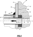
図4の実施例では、アパーチャ28は、管20の外側断面に実質的に対応する断面を有する。各管の連続部分32は、当接表面24Aを超えて突出する管の端部を取り囲む外側カラー50を備えている。
In the embodiment of FIG. 4, the
このカラー50は、膨張性材料から形成され、且つ、例えばセラミック材料から形成された周辺金輪54により取り囲まれた、リング52を備えている。その端部では、カラー50は、例えば、連続部分32の端部と金輪54の端部との間に介在されたセラミック材料でできたクラウン56を備えている。
The
カラーの総厚さは、例えば3mmから7mmの間にある。 The total thickness of the collar is, for example, between 3 mm and 7 mm.
本実施例では、断熱の増大したレベルは、排気ガスと、フランジ24に接触したシリンダーヘッドの一部分との間で得られる。
In this embodiment, an increased level of thermal insulation is obtained between the exhaust gas and the portion of the cylinder head that contacts the
Claims (10)
前記排気マニホルド(12)は、
外側シェル(22)と、該外側シェル(22)に溶接され、前記エンジンシリンダーヘッドに対して当接するための表面(24A)及び該当接表面(24A)で開口するとともに前記排気出口(14)に面している少なくとも1つのアパーチャ(28)を有するフランジ(24)と、
外側ケーシング(18)内に配置され、且つ、前記アパーチャ(28)を介して開口する少なくとも1つの内側チャンネル(20)と、
を有する外側ケーシング(18)を備えており、
前記内側チャンネル(20)又は該内側チャンネルの各々は、セラミック材料から形成され、
前記内側チャンネル(20)又は該内側チャンネルの各々は、前記アパーチャ(28)又は該アパーチャの各々を通して前記フランジ(24)の一方の側部から他方の側部へと延在し、前記当接表面(24A)を超えて外側に延在する前記外側ケーシングの外部に連続部分(32)を備え、
前記排気出口(14)は、前記排気マニホルド(12)に面して開口する覆いボア(34)を有し、前記排気マニホルドの前記内側チャンネル(20)又は該内側チャンネルの各々の前記連続部分(32)は、前記覆いボア(34)又は該覆いボアの各々によって画定された空間又は該空間の各々内に収容されており、前記覆いボア(34)と前記連続部分(32)との間の径方向のクリアランスは、0.5mmよりも小さい、ことを特徴とする、エンジン。An engine comprising a cylinder head (15) defining an exhaust outlet (14) and an exhaust manifold (12) adapted to the cylinder head (15),
The exhaust manifold (12)
An outer shell (22), a surface welded to the outer shell (22), a surface (24A) for contacting the engine cylinder head, and an appropriate contact surface (24A) and opening to the exhaust outlet (14) A flange (24) having at least one aperture (28) facing;
At least one inner channel (20) disposed in the outer casing (18) and opening through the aperture (28);
An outer casing (18) having
The inner channel (20) or each of the inner channels is formed from a ceramic material;
The inner channel (20) or each of the inner channels extends from one side of the flange (24) through the aperture (28) or each of the apertures to the other side, and the abutment surface (24A) comprising a continuous portion (32) outside the outer casing extending outwardly beyond,
The exhaust outlet (14) has a cover bore (34) that opens to face the exhaust manifold (12), the inner channel (20) of the exhaust manifold or the continuous portion of each of the inner channels ( 32), the cover bore (34) or are accommodated in each of the inter-spatial or spatial defined by each of said cover bore between said continuous portion and said cover bore (34) (32) An engine having a radial clearance of less than 0.5 mm.
Applications Claiming Priority (3)
| Application Number | Priority Date | Filing Date | Title |
|---|---|---|---|
| FR0504585 | 2005-05-04 | ||
| FR0504585A FR2885385B1 (en) | 2005-05-04 | 2005-05-04 | DOUBLE HULL COLLECTOR |
| PCT/FR2006/000970 WO2006117468A1 (en) | 2005-05-04 | 2006-04-28 | Double-shell manifold |
Publications (2)
| Publication Number | Publication Date |
|---|---|
| JP2008540898A JP2008540898A (en) | 2008-11-20 |
| JP5137817B2 true JP5137817B2 (en) | 2013-02-06 |
Family
ID=35429557
Family Applications (1)
| Application Number | Title | Priority Date | Filing Date |
|---|---|---|---|
| JP2008509468A Expired - Fee Related JP5137817B2 (en) | 2005-05-04 | 2006-04-28 | Double shell manifold |
Country Status (7)
| Country | Link |
|---|---|
| US (1) | US8104273B2 (en) |
| JP (1) | JP5137817B2 (en) |
| KR (1) | KR101293122B1 (en) |
| CN (1) | CN101189416B (en) |
| DE (1) | DE112006001133T5 (en) |
| FR (1) | FR2885385B1 (en) |
| WO (1) | WO2006117468A1 (en) |
Families Citing this family (17)
| Publication number | Priority date | Publication date | Assignee | Title |
|---|---|---|---|---|
| US7836692B2 (en) * | 2005-01-31 | 2010-11-23 | Faurecia Systemes D'echappement | Exhaust line element provided with a turbocompressor |
| DE102007062663A1 (en) * | 2007-12-24 | 2009-06-25 | J. Eberspächer GmbH & Co. KG | Sliding seat and pipe arrangement and exhaust treatment device |
| WO2009091540A1 (en) * | 2008-01-14 | 2009-07-23 | Metaldyne Company Llc | Dual-layer to flange welded joint |
| EP2340364B1 (en) * | 2008-10-01 | 2015-10-21 | Borgwarner Inc. | Exhaust flow insulator for an exhaust system device |
| AT509691B1 (en) * | 2010-03-18 | 2013-09-15 | Avl List Gmbh | INTERNAL COMBUSTION ENGINE WITH A CONNECTION ASSEMBLY FOR A CYLINDER HEAD |
| DE102010015271A1 (en) | 2010-04-15 | 2011-10-20 | J. Eberspächer GmbH & Co. KG | Exhaust gas treatment device |
| DE102010034743A1 (en) | 2010-08-19 | 2012-02-23 | J. Eberspächer GmbH & Co. KG | Exhaust gas purification device, exhaust system, removal process |
| WO2012063096A1 (en) * | 2010-11-08 | 2012-05-18 | Faurecia Systemes D'echappement | Exhaust manifold with thin flanges |
| US8763383B2 (en) * | 2010-11-17 | 2014-07-01 | Evolution Motorsports | Exhaust flow divider |
| JP5883885B2 (en) * | 2011-01-27 | 2016-03-15 | ボーグワーナー インコーポレーテッド | Adjusting flap device |
| US9086007B2 (en) * | 2012-12-21 | 2015-07-21 | Caterpillar Inc. | System and method for accommodating aftertreatment bricks |
| DE102013109446B4 (en) * | 2013-08-30 | 2015-11-26 | Benteler Automobiltechnik Gmbh | Exhaust manifold with insulation sleeve |
| DE102014103314B4 (en) * | 2014-03-12 | 2018-07-12 | Tenneco Gmbh | Exhaust pipe flange, group flange and exhaust system |
| US10662854B2 (en) * | 2016-10-10 | 2020-05-26 | Egc Enterprises, Inc. | Exhaust sealing joint |
| CN107237676A (en) * | 2017-06-30 | 2017-10-10 | 潍柴动力股份有限公司 | The casting method of the exhaust pipe of engine, engine and the exhaust pipe of engine |
| CN107387219A (en) * | 2017-07-19 | 2017-11-24 | 冠立科技扬州有限公司 | A kind of motorcycle exhaust blast pipe |
| GB2571270A (en) * | 2018-02-21 | 2019-08-28 | Jaguar Land Rover Ltd | Exhaust manifold assembly |
Family Cites Families (12)
| Publication number | Priority date | Publication date | Assignee | Title |
|---|---|---|---|---|
| FR2272966A1 (en) * | 1974-05-28 | 1975-12-26 | Toyota Motor Co Ltd | Thermally-insulating ceramic sleeves - cast into metal components for internal combustion engines to ensure combustion of exhaust gas |
| US4197704A (en) * | 1976-06-11 | 1980-04-15 | Honda Giken Kogyo Kabushiki Kaisha | Exhaust manifold for internal combustion engine |
| JPH01280616A (en) * | 1988-05-02 | 1989-11-10 | Ngk Insulators Ltd | Enveloping cast of heat insulating ceramic for exhaust channel of internal combustion engine and its manufacture |
| JPH02167701A (en) * | 1988-12-21 | 1990-06-28 | Ngk Insulators Ltd | Manufacture of multi-branched ceramic pipe for thermally insulating exhaust channel |
| JP2965631B2 (en) * | 1990-07-12 | 1999-10-18 | 本田技研工業株式会社 | Exhaust device |
| US5392601A (en) * | 1993-02-25 | 1995-02-28 | Michael D. Epstein | Exhaust system for an internal combustion engine |
| US5419127A (en) * | 1993-11-22 | 1995-05-30 | Soundwich Inc | Insulated damped exhaust manifold |
| JPH0828257A (en) * | 1994-07-11 | 1996-01-30 | Toyota Motor Corp | Double exhaust pipe |
| US5718046A (en) * | 1995-12-11 | 1998-02-17 | General Motors Corporation | Method of making a ceramic coated exhaust manifold and method |
| JPH09236014A (en) * | 1996-02-29 | 1997-09-09 | Isuzu Motors Ltd | Thermal insulation manifold |
| US5961154A (en) * | 1998-09-16 | 1999-10-05 | Williams; Douglas | Fume duct joint with clamping collar |
| DE10054006A1 (en) * | 2000-11-01 | 2002-05-08 | Daimler Chrysler Ag | Exhaust manifold, for internal combustion engine, is insulated by air and is formed as inner tube, which penetrates into cylinder head, and outer tube, which is fitted to cylinder head by fixing bracket. |
-
2005
- 2005-05-04 FR FR0504585A patent/FR2885385B1/en not_active Expired - Fee Related
-
2006
- 2006-04-28 WO PCT/FR2006/000970 patent/WO2006117468A1/en active Application Filing
- 2006-04-28 US US11/913,586 patent/US8104273B2/en not_active Expired - Fee Related
- 2006-04-28 DE DE112006001133T patent/DE112006001133T5/en not_active Withdrawn
- 2006-04-28 CN CN2006800194481A patent/CN101189416B/en not_active Expired - Fee Related
- 2006-04-28 KR KR1020077028206A patent/KR101293122B1/en not_active IP Right Cessation
- 2006-04-28 JP JP2008509468A patent/JP5137817B2/en not_active Expired - Fee Related
Also Published As
| Publication number | Publication date |
|---|---|
| KR101293122B1 (en) | 2013-08-12 |
| US20090266065A1 (en) | 2009-10-29 |
| US8104273B2 (en) | 2012-01-31 |
| WO2006117468A1 (en) | 2006-11-09 |
| KR20080005304A (en) | 2008-01-10 |
| FR2885385A1 (en) | 2006-11-10 |
| JP2008540898A (en) | 2008-11-20 |
| CN101189416B (en) | 2013-08-21 |
| CN101189416A (en) | 2008-05-28 |
| FR2885385B1 (en) | 2007-07-27 |
| DE112006001133T5 (en) | 2008-03-27 |
Similar Documents
| Publication | Publication Date | Title |
|---|---|---|
| JP5137817B2 (en) | Double shell manifold | |
| US4693338A (en) | Exhaust muffler for a motor vehicle or the like | |
| US6604358B2 (en) | Exhaust manifold | |
| US7434390B2 (en) | Air-gap-insulated exhaust manifold | |
| KR100517786B1 (en) | Catalyst support assembly to be mounted in an engine compartment | |
| JP5389332B2 (en) | Exhaust system parts | |
| JP2012515295A (en) | Connection arrangement of turbine housing and bearing housing and exhaust turbocharger | |
| US8656709B2 (en) | Dual-layer to flange welded joint | |
| JP2007154660A (en) | Exhaust manifold | |
| JP2011122594A (en) | Exhaust manifold having baffle plate | |
| JP5350221B2 (en) | Combined exhaust manifold | |
| US5729975A (en) | Semi-airgap manifold formation | |
| US8261778B2 (en) | Motor vehicle exhaust pipe | |
| JP2001263054A (en) | Exhaust pipe | |
| JP2019085949A (en) | Turbine housing | |
| WO1999067513A1 (en) | Improved catalyser housing | |
| US9410470B2 (en) | Exhaust manifold | |
| US4055043A (en) | Manifold reactor | |
| KR101305560B1 (en) | Exhaust pipe system for multicylinder gas and diesel engine | |
| US20180149068A1 (en) | Internal combustion engine | |
| JPH07224649A (en) | Exhaust manifold structure | |
| JPH053699Y2 (en) | ||
| JPS636418Y2 (en) | ||
| JP2000027644A (en) | Exhaust pipe connection structure utilizing spherical joint | |
| JP2022151013A (en) | Silencer |
Legal Events
| Date | Code | Title | Description |
|---|---|---|---|
| A621 | Written request for application examination |
Free format text: JAPANESE INTERMEDIATE CODE: A621 Effective date: 20090403 |
|
| A977 | Report on retrieval |
Free format text: JAPANESE INTERMEDIATE CODE: A971007 Effective date: 20110418 |
|
| A131 | Notification of reasons for refusal |
Free format text: JAPANESE INTERMEDIATE CODE: A131 Effective date: 20110420 |
|
| A601 | Written request for extension of time |
Free format text: JAPANESE INTERMEDIATE CODE: A601 Effective date: 20110715 |
|
| A602 | Written permission of extension of time |
Free format text: JAPANESE INTERMEDIATE CODE: A602 Effective date: 20110725 |
|
| RD04 | Notification of resignation of power of attorney |
Free format text: JAPANESE INTERMEDIATE CODE: A7424 Effective date: 20110915 |
|
| A521 | Written amendment |
Free format text: JAPANESE INTERMEDIATE CODE: A523 Effective date: 20111014 |
|
| A131 | Notification of reasons for refusal |
Free format text: JAPANESE INTERMEDIATE CODE: A131 Effective date: 20120326 |
|
| A601 | Written request for extension of time |
Free format text: JAPANESE INTERMEDIATE CODE: A601 Effective date: 20120625 |
|
| A521 | Written amendment |
Free format text: JAPANESE INTERMEDIATE CODE: A523 Effective date: 20120627 |
|
| A602 | Written permission of extension of time |
Free format text: JAPANESE INTERMEDIATE CODE: A602 Effective date: 20120702 |
|
| TRDD | Decision of grant or rejection written | ||
| A01 | Written decision to grant a patent or to grant a registration (utility model) |
Free format text: JAPANESE INTERMEDIATE CODE: A01 Effective date: 20121026 |
|
| A01 | Written decision to grant a patent or to grant a registration (utility model) |
Free format text: JAPANESE INTERMEDIATE CODE: A01 |
|
| A61 | First payment of annual fees (during grant procedure) |
Free format text: JAPANESE INTERMEDIATE CODE: A61 Effective date: 20121113 |
|
| R150 | Certificate of patent or registration of utility model |
Free format text: JAPANESE INTERMEDIATE CODE: R150 |
|
| FPAY | Renewal fee payment (event date is renewal date of database) |
Free format text: PAYMENT UNTIL: 20151122 Year of fee payment: 3 |
|
| LAPS | Cancellation because of no payment of annual fees |