JP5136297B2 - Electric power steering device - Google Patents
Electric power steering device Download PDFInfo
- Publication number
- JP5136297B2 JP5136297B2 JP2008220660A JP2008220660A JP5136297B2 JP 5136297 B2 JP5136297 B2 JP 5136297B2 JP 2008220660 A JP2008220660 A JP 2008220660A JP 2008220660 A JP2008220660 A JP 2008220660A JP 5136297 B2 JP5136297 B2 JP 5136297B2
- Authority
- JP
- Japan
- Prior art keywords
- output shaft
- axis
- shaft
- cover
- electric power
- Prior art date
- Legal status (The legal status is an assumption and is not a legal conclusion. Google has not performed a legal analysis and makes no representation as to the accuracy of the status listed.)
- Active
Links
Images


Description
本発明はステアリング装置、特に、電動モータを駆動して所要の操舵補助力をステアリングギヤに付与する電動式パワーステアリング装置に関する。 The present invention relates to a steering apparatus, and more particularly to an electric power steering apparatus that drives an electric motor to apply a required steering assist force to a steering gear.
電動式パワーステアリング装置は、特許文献1に示すように、電動モータを駆動してウォームに噛み合うウォームホイールを所要の操舵補助力で回転させ、ウォームホイールを有する出力軸を回転させて、ステアリングギヤに連結されたタイロッドを移動させて、舵輪の向きを変更している。 As shown in Patent Document 1, an electric power steering device drives an electric motor to rotate a worm wheel that meshes with a worm with a required steering assist force, and rotates an output shaft having the worm wheel so that a steering gear is used. The direction of the steering wheel is changed by moving the connected tie rods.
図6、図7に、このような従来の電動式パワーステアリング装置を示す。図6は、従来の電動式パワーステアリング装置の要部の縦断面図、図7は図6のP矢視図である。図6及び図7に示すように、電動式パワーステアリング装置のアシスト装置20のギヤハウジング21には、インナーシャフト(入力軸)12Bと出力軸23が同一中心軸線上に配置され、出力軸23が軸受(深みぞ形ラジアル玉軸受)41によって、カバー22に回転可能に軸支されている。
6 and 7 show such a conventional electric power steering apparatus. FIG. 6 is a longitudinal sectional view of a main part of a conventional electric power steering apparatus, and FIG. 7 is a view taken in the direction of arrow P in FIG. As shown in FIGS. 6 and 7, an inner shaft (input shaft) 12 </ b> B and an
カバー22は、ギヤハウジング21の左側開放端を覆っている。インナーシャフト12Bと出力軸23は、トーションバー24によって連結されている。出力軸23の回転は、自在継手15、中間シャフト16を介して図示しないステアリングギヤに伝達され、ステアリングギヤに連結されたタイロッドを介して舵輪の向きを変更する。
The
出力軸23の中間部には円盤状の芯金52が圧入され、芯金52の外周には、ウォーム53と噛み合うウォームホイール51が圧入されている。ウォーム53は、電動モータ25(図7参照)によって駆動される。芯金52の右端面521は出力軸23の段部231に当接して、出力軸23に対して芯金52が右側(車体後方側)に移動しないように規制している。出力軸23は、芯金52の左端面522に当接する軸受41により、ギヤハウジング21のカバー22に回転可能に軸支されている。
A disc-shaped
出力軸23にねじ込まれたナット26は、軸受41の内輪を、芯金52の左端面522との間で挟み込んでいる。また、軸受41の外輪は、カバー22に形成された軸受孔221にしまりばめで圧入され、この軸受孔221のリング溝に挿入された止め輪27によって、カバー22に固定されている。軸受41の外輪を軸受孔221にしまりばめで圧入することにより、軸受41の内部隙間は、負の値に設定されている。
The
出力軸23は、段部231の右側の外周が、軸受(深みぞ形ラジアル玉軸受)42によって、ギヤハウジング21に回転可能に軸支されている。軸受42の外輪は、ギヤハウジング21に形成された軸受孔211に圧入され、軸受42の内輪は、その左端面が芯金52の右端面521に当接している。
The
インナーシャフト12Bにその右端(車体後方側端部)が圧入されたトーションバー24は、その左端(車体前方側端部)が、図示しないピンによって出力軸23の左端に連結されている。また、トーションバー24の中間部が、出力軸23の右端にブッシュ29によって外周を軸支されている。
The
トーションバー24に作用するトルクを検出するトルクセンサー61は、センサーシャフト部62、検出コイル63及び64、円筒部材65から構成されている。センサーシャフト部62は、出力軸23の右端(車体後方側端部)に一体的に形成され、ギヤハウジング21の内側に圧入されたヨーク66に、検出コイル63及び64が配置されている。円筒部材65は、センサーシャフト部62の外周と、検出コイル63及び64の内周との間の隙間に配置されている。
A
円筒部材65はインナーシャフト12Bの左端(車体前方側端部)に固定され、センサーシャフト部62には、軸方向に延びた複数の凸条が円周方向に等間隔に形成されている。円筒部材65には、検出コイル63及び64に対向する位置に、円周方向に等間隔に複数の長方形の窓が形成されている。
The
図示しないステアリングホイールを操作してインナーシャフト12Bが回転すると、その回転力がトーションバー24を介して出力軸23に伝達される。この時、舵輪側の抵抗によって、インナーシャフト12Bと出力軸23を連結するトーションバー24に捩れが生じ、センサーシャフト部62の表面の凸条と円筒部材65の窓との間に相対回転が生じる。
When the
この相対回転で、センサーシャフト部62に発生する磁束が増減し、この磁束の増減を検出コイル63及び64がインダクタンスの変化として検出する。この検出結果から、トーションバー24に作用するトルクを検出し、電動モータ25を駆動してウォーム53を所要の操舵補助力で回転させる。ウォーム53の回転は、ウォームホイール51、出力軸23、自在継手15、中間シャフト16を介してステアリングギヤに伝達され、ステアリングギヤに連結されたタイロッドを介して舵輪の向きを変更する。
With this relative rotation, the magnetic flux generated in the
自在継手15は、図6に示すように、ジョイント角β(20度から50度が一般的)で交差しているため、中間シャフト16が回転トルクを受けると、自在継手15に生じる二次偶力によって、出力軸23には、大きなモーメント荷重が作用する。このモーメント荷重Mは、M=Tcosθ・tanβで表される。
As shown in FIG. 6, the
ここで、Tが中間シャフト16の回転トルク、βがジョイント角、θが自在継手15のヨークの位相角である。このモーメント荷重Mは、ヨークの位相角が0度(自在継手15のヨークの位相が、図6、図7の状態)の時、最も大きな値となる。
Here, T is the rotational torque of the
このモーメント荷重Mは、図6、図7に示すように、自在継手15の十字軸151の中心を通るZ軸回りの回転力となる。従って、出力軸23には、図7のY軸方向(出力軸23の軸線と中間シャフト16の軸線を通る平面に対して垂直方向)に大きな荷重が加わることになる。
As shown in FIGS. 6 and 7, the moment load M becomes a rotational force around the Z axis passing through the center of the
従って、出力軸23を軸支する軸受41には、Y軸方向に大きな荷重が作用する。その結果、軸受41の玉のうち、Y軸方向にある玉の面圧が過大になり、軸受41の摩耗が大きくなって耐久性が低下したり、乗り上げ傷が発生して異音が発生し、運転者に不快感を与える恐れがあった。
Therefore, a large load acts on the
本発明は、出力軸を軸支する軸受の耐久性を向上させると共に、異音の発生を防止して、運転者に不快感を与えないようにした電動式パワーステアリング装置を提供することを課題とする。 An object of the present invention is to provide an electric power steering device that improves the durability of a bearing that supports an output shaft and prevents the generation of abnormal noise so as not to cause discomfort to the driver. And
上記課題は以下の手段によって解決される。すなわち、第1番目の発明は、ギヤハウジング、上記ギヤハウジングに挿通されステアリングホイールの回転が伝達される入力軸、上記入力軸に連結された出力軸、上記出力軸に自在継手を介して連結され、出力軸の回転を車輪側に伝達する中間シャフト、上記入力軸に作用するトルクを検出するトルクセンサー、上記トルクセンサーの検出値に応じて所定の操舵補助力を上記出力軸に付与する電動モータ、上記ギヤハウジングを覆うカバーと上記出力軸との間に介挿され、その外輪がカバーにしまりばめで内嵌され、その内部隙間が負の値で、上記出力軸を回転可能に軸支する軸受を備え、上記カバーは、上記出力軸の軸線と中間シャフトの軸線を通る平面に対して垂直方向の剛性が、他の方向の剛性よりも小さく形成されていることを特徴とする電動式パワーステアリング装置である。 The above problem is solved by the following means. That is, the first invention is a gear housing, an input shaft that is inserted through the gear housing and to which the rotation of the steering wheel is transmitted, an output shaft that is coupled to the input shaft, and is coupled to the output shaft via a universal joint. An intermediate shaft that transmits the rotation of the output shaft to the wheel side, a torque sensor that detects torque acting on the input shaft, and an electric motor that applies a predetermined steering assist force to the output shaft in accordance with a detection value of the torque sensor The output shaft is inserted between the cover that covers the gear housing and the output shaft, the outer ring is fitted into the cover with an interference fit, and the output shaft is rotatably supported with a negative internal clearance. The cover includes a bearing, and the cover is formed so that rigidity in a direction perpendicular to a plane passing through the axis of the output shaft and the axis of the intermediate shaft is smaller than rigidity in other directions. An electric power steering apparatus according to.
第2番目の発明は、第1番目の発明の電動式パワーステアリング装置において、上記カバーには、上記出力軸の軸線と中間シャフトの軸線を通る平面に対して垂直方向に、軸方向の肉厚が他の方向の肉厚よりも薄い薄肉部が形成されていることを特徴とする電動式パワーステアリング装置である。 A second aspect of the invention is the electric power steering apparatus according to the first aspect of the invention, wherein the cover has an axial thickness perpendicular to a plane passing through the axis of the output shaft and the axis of the intermediate shaft. Is an electric power steering device characterized in that a thin portion thinner than the thickness in the other direction is formed.
第3番目の発明は、第1番目の発明の電動式パワーステアリング装置において、上記カバーは、上記カバーの軸心から放射状に形成されたリブを有し、上記出力軸の軸線と中間シャフトの軸線を通る平面に対して垂直方向のリブが省略されていることを特徴とする電動式パワーステアリング装置である。 A third invention is the electric power steering apparatus according to the first invention, wherein the cover has ribs formed radially from the axis of the cover, and the axis of the output shaft and the axis of the intermediate shaft The electric power steering apparatus is characterized in that ribs in the direction perpendicular to the plane passing through the line are omitted.
第4番目の発明は、第1番目の発明の電動式パワーステアリング装置において、上記カバーの軸心から放射状に形成されたリブの肉厚は、上記出力軸の軸線と中間シャフトの軸線を通る平面に対して垂直方向のリブが他の方向のリブよりも薄く形成されていることを特徴とする電動式パワーステアリング装置である。 According to a fourth aspect of the invention, in the electric power steering apparatus of the first aspect, the thickness of the rib formed radially from the axis of the cover is a plane passing through the axis of the output shaft and the axis of the intermediate shaft. The electric power steering apparatus is characterized in that the rib in the vertical direction is formed thinner than the rib in the other direction.
本発明の電動式パワーステアリング装置では、ギヤハウジングを覆うカバーと出力軸との間に介挿され、その外輪がカバーにしまりばめで内嵌され、その内部隙間が負の値で、出力軸を回転可能に軸支する軸受を備え、カバーは、出力軸の軸線と中間シャフトの軸線を通る平面に対して垂直方向の剛性が、他の方向の剛性よりも小さく形成されている。 In the electric power steering apparatus of the present invention, the outer ring is inserted between the cover that covers the gear housing and the output shaft, the outer ring is fitted into the cover with an interference fit, the internal clearance is a negative value, and the output shaft is The cover is provided with a rotatably supported bearing, and the cover is formed so that the rigidity in the direction perpendicular to the plane passing through the axis of the output shaft and the axis of the intermediate shaft is smaller than the rigidity in the other direction.
従って、軸受の外輪は、出力軸の軸線と中間シャフトの軸線を通る平面に対して垂直方向が長径の楕円形状になる。そのため、外輪の長径方向にある玉の面圧が、その他の玉の面圧よりも小さくなっている。従って、外輪の長径方向に大きな荷重が加わっても、外輪の長径方向にある玉の面圧が過大にならず、軸受の耐久性が向上すると共に、異音の発生を防止して、運転者に不快感を与えない。 Therefore, the outer ring of the bearing has an elliptical shape whose major axis is perpendicular to the plane passing through the axis of the output shaft and the axis of the intermediate shaft. For this reason, the surface pressure of the balls in the major axis direction of the outer ring is smaller than the surface pressure of the other balls. Therefore, even when a large load is applied in the major axis direction of the outer ring, the surface pressure of the balls in the major axis direction of the outer ring does not become excessive, and the durability of the bearing is improved and the generation of abnormal noise is prevented. Does not cause any discomfort.
以下、図面に基づいて本発明の実施例1から実施例3を説明する。 Embodiments 1 to 3 of the present invention will be described below with reference to the drawings.
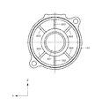
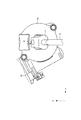
図1は本発明の実施例1の電動式パワーステアリング装置の全体を示し、一部を切断した全体正面図である。図2は図1の要部の縦断面図、図3は図1のカバーの正面図である。 FIG. 1 is an overall front view showing a whole of an electric power steering apparatus according to a first embodiment of the present invention, with a part thereof cut. 2 is a longitudinal sectional view of the main part of FIG. 1, and FIG. 3 is a front view of the cover of FIG.
図1から図3に示すように、本発明の電動式パワーステアリング装置は、車体後方側(図1、図2の右側)にステアリングホイール11を装着可能なステアリングシャフト12と、このステアリングシャフト12を挿通したステアリングコラム13と、このステアリングシャフト12に補助トルクを付与する為のアシスト装置20と、このステアリングシャフト12の車体前方側(図1、図2の左側)に、図示しないラック/ピニオン機構を介して連結されたステアリングギヤ30とを備える。
As shown in FIGS. 1 to 3, the electric power steering apparatus of the present invention includes a
ステアリングシャフト12は、アウターシャフト12Aとインナーシャフト(入力軸)12Bとを、スプライン係合により、回転力を伝達自在に、かつ軸方向に関して相対変位可能に組み合わせている。従って、上記アウターシャフト12Aとインナーシャフト12Bとは、衝突時に、このスプライン係合部が相対摺動して、全長を縮めることができる。
In the steering
また、上記ステアリングシャフト12を挿通した筒状のステアリングコラム13は、アウターコラム13Aとインナーコラム13Bとをテレスコピック移動可能に組み合わせており、衝突時に軸方向の衝撃が加わった場合に、この衝撃によるエネルギを吸収しつつ全長が縮まる、所謂コラプシブル構造としている。
Further, the
そして、上記インナーコラム13Bの車体前方側端部を、アシスト装置20のギヤハウジング21の車体後方側端部に圧入嵌合して固定している。また、上記インナーシャフト(入力軸)12Bの車体前方側端部を、このギヤハウジング21の内側に通し、アシスト装置20の出力軸(雌シャフト)23の車体後方側端部に結合している。
The vehicle body front side end portion of the
ステアリングコラム13は、その中間部を支持ブラケット14により、ダッシュボードの下面等、車体18の一部に支承している。また、この支持ブラケット14と車体18との間に、図示しない係止部を設けて、この支持ブラケット14に車体前方側に向かう方向の衝撃が加わった場合に、この支持ブラケット14が上記係止部から外れ、車体前方側に移動するようにしている。
The
また、上記ギヤハウジング21の上端部も、上記車体18の一部に枢動可能に支承している。また、本実施例の場合には、チルト機構及びテレスコピック機構を設けることにより、上記ステアリングホイール11の高さ位置、及び、車体前後方向位置の調節を自在としている。このようなチルト機構及びテレスコピック機構は、従来から周知であり、本発明の特徴部分でもない為、詳しい説明は省略する。
The upper end portion of the
上記ギヤハウジング21の車体前方側端面から突出した出力軸23は、自在継手15を介して、中間シャフト16の後端部に連結している。また、この中間シャフト16の前端部に、別の自在継手17を介して、ステアリングギヤ30の入力軸31を連結している。図示しないピニオンが、この入力軸31の車体前方側端部に形成されている。また、図示しないラックが、このピニオンに噛み合っており、ステアリングホイール11の回転が、タイロッド32を移動させて、図示しない車輪を操舵する。
The
図2及び図3に示すように、アシスト装置20のギヤハウジング21には、インナーシャフト(入力軸)12Bと出力軸23が同一中心軸線上に配置され、出力軸23が軸受(深みぞ形ラジアル玉軸受)41によって、カバー22に回転可能に軸支されている。カバー22は、ギヤハウジング21の左側開放端を覆っている。インナーシャフト12Bと出力軸23は、トーションバー24によって連結されている。
2 and 3, an inner shaft (input shaft) 12B and an
出力軸23の中間部には円盤状の芯金52が圧入され、芯金52の外周には、ウォーム53と噛み合うウォームホイール51が圧入されている。図1に示すように、電動モータ25のケース251がギヤハウジング21に固定され、この電動モータ25の出力軸にウォーム53が連結されている。
A disc-shaped cored
芯金52の右端面521は出力軸23の段部231に当接して、出力軸23に対して芯金52が右側(車体後方側)に移動しないように規制している。出力軸23は、芯金52の左端面522に当接する軸受(深みぞ形ラジアル玉軸受)41により、ギヤハウジング21のカバー22に回転可能に軸支されている。
The
出力軸23にねじ込まれたナット26は、軸受41の内輪を、芯金52の左端面522との間で挟み込んでいる。また、軸受41の外輪は、カバー22に形成された軸受孔221にしまりばめで圧入され、この軸受孔221のリング溝に挿入された止め輪27によって、カバー22に固定されている。軸受41の外輪を軸受孔221にしまりばめで圧入することにより、軸受41の内部隙間は、負の値に設定されている。
The
図2及び図3に示すように、カバー22には、肉盗み部222、222が形成されている。肉盗み部222、222は、カバー22の軸受孔221を挟んで、図3のY軸方向(出力軸23の軸線と中間シャフト16の軸線を通る平面に対して垂直方向)の両側に形成されている。
As shown in FIGS. 2 and 3, the
従って、カバー22のY軸方向には、軸方向の肉厚が他の方向の肉厚よりも薄い薄肉部が形成されているため、カバー22のY軸方向の剛性が、他の方向の剛性よりも小さく形成されている。そのため、軸受孔221に軸受41の外輪をしまりばめで圧入すると、軸受41の外輪は、Y軸方向が長径でZ軸方向が短径の楕円形状になる。従って、軸受41
のY軸方向にある玉の面圧が、その他の方向にある玉の面圧よりも小さくなる。
Accordingly, since the thin portion is formed in the Y-axis direction of the
The surface pressure of the balls in the Y-axis direction is smaller than the surface pressure of the balls in the other directions.
出力軸23は、段部231の右側の外周が、軸受(深みぞ形ラジアル玉軸受)42によって、ギヤハウジング21に回転可能に軸支されている。軸受42の外輪は、ギヤハウジング21に形成された軸受孔211に圧入され、軸受42の内輪は、その左端面が芯金52の右端面521に当接している。
The
インナーシャフト12Bにその右端(車体後方側端部)が圧入されたトーションバー24は、その左端(車体前方側端部)が、図示しないピンによって出力軸23の左端に連結されている。また、トーションバー24の中間部が、出力軸23の右端にブッシュ29によって外周を軸支されている。
The
トーションバー24に作用するトルクを検出するトルクセンサー61は、センサーシャフト部62、検出コイル63及び64、円筒部材65から構成されている。センサーシャフト部62は、出力軸23の右端(車体後方側端部)に一体的に形成され、ギヤハウジング21の内側に圧入されたヨーク66に、検出コイル63及び64が配置されている。円筒部材65は、センサーシャフト部62の外周と、検出コイル63及び64の内周との間の隙間に配置されている。
A
円筒部材65はインナーシャフト12Bの左端(車体前方側端部)に固定され、センサーシャフト部62には、軸方向に延びた複数の凸条が円周方向に等間隔に形成されている。円筒部材65には、検出コイル63及び64に対向する位置に、円周方向に等間隔に複数の長方形の窓が形成されている。
The
ステアリングホイール11を操作してインナーシャフト12Bが回転すると、その回転力がトーションバー24を介して出力軸23に伝達される。この時、舵輪側の抵抗によって、インナーシャフト12Bと出力軸23を連結するトーションバー24に捩れが生じ、センサーシャフト部62の表面の凸条と円筒部材65の窓との間に相対回転が生じる。
When the
この相対回転で、センサーシャフト部62に発生する磁束が増減し、この磁束の増減を検出コイル63及び64がインダクタンスの変化として検出する。この検出結果から、トーションバー24に作用するトルクを検出し、電動モータ25を駆動してウォーム53を所要の操舵補助力で回転させる。ウォーム53の回転は、ウォームホイール51、出力軸23、自在継手15、中間シャフト16を介してステアリングギヤ30に伝達され、ステアリングギヤ30に連結されたタイロッド32を介して舵輪の向きを変更する。
With this relative rotation, the magnetic flux generated in the
本発明の実施例1で、従来例と同様に、自在継手15に生じる二次偶力によって、出力軸23にモーメント荷重Mが作用すると、出力軸23には、図3のY軸方向(出力軸23の軸線と中間シャフト16の軸線を通る平面に対して垂直方向)に大きな荷重が加わる。
In the first embodiment of the present invention, when the moment load M acts on the
本発明の実施例1では、軸受41の外輪は、Y軸方向が長径でZ軸方向が短径の楕円形状になって圧入されているため、軸受41のY軸方向にある玉の面圧が、その他の方向にある玉の面圧よりも小さくなっている。従って、Y軸方向に大きな荷重が加わっても、Y軸方向にある玉の面圧が過大にならず、軸受の耐久性が向上すると共に、異音の発生を防止して、運転者に不快感を与えない。
In the first embodiment of the present invention, the outer ring of the
次に本発明の実施例2について説明する。図4は本発明の実施例2を示すカバーの背面図である。以下の説明では、上記実施例1と異なる構造部分と作用についてのみ説明し、重複する説明は省略する。また、同一部品には同一番号を付して説明する。 Next, a second embodiment of the present invention will be described. FIG. 4 is a rear view of the cover showing the second embodiment of the present invention. In the following description, only structural portions and operations different from those of the first embodiment will be described, and overlapping descriptions will be omitted. Further, the same parts will be described with the same numbers.
実施例2は、カバー22のリブの配置によって、カバー22のY軸方向の剛性を、他の方向の剛性よりも小さく形成した例である。すなわち、図4に示すように、カバー22の背面には、カバー22の軸心から放射状に、6本のリブ223が形成されているが、Y軸方向のリブは省略されている。そのため、カバー22のY軸方向の剛性が、他の方向の剛性よりも小さく形成されている。
The second embodiment is an example in which the rigidity of the
従って、軸受孔221に軸受41の外輪をしまりばめで圧入すると、軸受41の外輪は、Y軸方向が長径でZ軸方向が短径の楕円形状になり、軸受41のY軸方向にある玉の面圧が、その他の方向にある玉の面圧よりも小さくなる。そのため、Y軸方向に大きな荷重が加わっても、Y軸方向にある玉の面圧が過大にならず、軸受の耐久性が向上すると共に、異音の発生を防止して、運転者に不快感を与えない。
Therefore, when the outer ring of the
次に本発明の実施例3について説明する。図5は本発明の実施例3を示すカバーの背面図である。以下の説明では、上記実施例と異なる構造部分と作用についてのみ説明し、重複する説明は省略する。また、同一部品には同一番号を付して説明する。 Next, a third embodiment of the present invention will be described. FIG. 5 is a rear view of the cover showing the third embodiment of the present invention. In the following description, only structural portions and operations different from the above embodiment will be described, and redundant description will be omitted. Further, the same parts will be described with the same numbers.
実施例3は、カバー22のリブの肉厚を変えることによって、カバー22のY軸方向の剛性を、他の方向の剛性よりも小さく形成した例である。すなわち、図5に示すように、カバー22の背面には、カバー22の軸心から放射状に、45度間隔で8本のリブが形成されているが、Y軸方向の2本のリブ225、225の肉厚T1が、他の方向の6本のリブ224の肉厚T2よりも薄く形成されている。そのため、カバー22のY軸方向の剛性が、他の方向の剛性よりも小さく形成されている。
The third embodiment is an example in which the rigidity of the
従って、軸受孔221に軸受41の外輪をしまりばめで圧入すると、軸受41の外輪は、Y軸方向が長径でZ軸方向が短径の楕円形状になり、軸受41のY軸方向にある玉の面圧が、その他の方向にある玉の面圧よりも小さくなる。そのため、Y軸方向に大きな荷重が加わっても、Y軸方向にある玉の面圧が過大にならず、軸受の耐久性が向上すると共に、異音の発生を防止して、運転者に不快感を与えない。
Therefore, when the outer ring of the
11 ステアリングホイール
12 ステアリングシャフト
12A アウターシャフト
12B インナーシャフト
13 ステアリングコラム
13A アウターコラム
13B インナーコラム
14 支持ブラケット
15 自在継手
151 十字軸
16 中間シャフト
17 自在継手
18 車体
20 アシスト装置
21 ギヤハウジング
211 軸受孔
22 カバー
221 軸受孔
222 肉盗み部
223、224、225 リブ
23 出力軸
231 段部
24 トーションバー
25 電動モータ
251 ケース
26 ナット
27 止め輪
29 ブッシュ
30 ステアリングギヤ
31 入力軸
32 タイロッド
41 軸受(深みぞ形ラジアル玉軸受)
42 軸受(深みぞ形ラジアル玉軸受)
51 ウォームホイール
52 芯金
521 右端面
522 左端面
53 ウォーム
61 トルクセンサー
62 センサーシャフト部
63、64 検出コイル
65 円筒部材
66 ヨーク
DESCRIPTION OF
42 Bearing (Deep groove radial ball bearing)
51
Claims (4)
上記ギヤハウジングに挿通されステアリングホイールの回転が伝達される入力軸、
上記入力軸に連結された出力軸、
上記出力軸に自在継手を介して連結され、出力軸の回転を車輪側に伝達する中間シャフト、
上記入力軸に作用するトルクを検出するトルクセンサー、
上記トルクセンサーの検出値に応じて所定の操舵補助力を上記出力軸に付与する電動モータ、
上記ギヤハウジングを覆うカバーと上記出力軸との間に介挿され、その外輪がカバーにしまりばめで内嵌され、その内部隙間が負の値で、上記出力軸を回転可能に軸支する軸受を備え、
上記カバーは、上記出力軸の軸線と中間シャフトの軸線を通る平面に対して垂直方向の剛性が、他の方向の剛性よりも小さく形成されていること
を特徴とする電動式パワーステアリング装置。 Gear housing,
An input shaft that is inserted into the gear housing and transmits the rotation of the steering wheel;
An output shaft connected to the input shaft,
An intermediate shaft connected to the output shaft via a universal joint and transmitting the rotation of the output shaft to the wheel side;
A torque sensor for detecting torque acting on the input shaft;
An electric motor that applies a predetermined steering assist force to the output shaft in accordance with a detection value of the torque sensor;
A bearing that is inserted between a cover that covers the gear housing and the output shaft, whose outer ring is fitted into the cover with an interference fit, and whose internal clearance is a negative value and rotatably supports the output shaft With
The electric power steering apparatus according to claim 1, wherein the cover is formed so that rigidity in a direction perpendicular to a plane passing through the axis of the output shaft and the axis of the intermediate shaft is smaller than rigidity in other directions.
上記カバーには、
上記出力軸の軸線と中間シャフトの軸線を通る平面に対して垂直方向に、軸方向の肉厚が他の方向の肉厚よりも薄い薄肉部が形成されていること
を特徴とする電動式パワーステアリング装置。 In the electric power steering apparatus according to claim 1,
The cover above
An electric power characterized in that a thin-walled portion is formed in a direction perpendicular to a plane passing through the axis of the output shaft and the axis of the intermediate shaft, and the thickness in the axial direction is thinner than the thickness in the other direction. Steering device.
上記カバーは、
上記カバーの軸心から放射状に形成されたリブを有し、
上記出力軸の軸線と中間シャフトの軸線を通る平面に対して垂直方向のリブが省略されていること
を特徴とする電動式パワーステアリング装置。 In the electric power steering apparatus according to claim 1,
The above cover
Having ribs formed radially from the axis of the cover;
An electric power steering apparatus characterized in that a rib perpendicular to a plane passing through the axis of the output shaft and the axis of the intermediate shaft is omitted.
上記カバーの軸心から放射状に形成されたリブの肉厚は、
上記出力軸の軸線と中間シャフトの軸線を通る平面に対して垂直方向のリブが他の方向のリブよりも薄く形成されていること
を特徴とする電動式パワーステアリング装置。 In the electric power steering apparatus according to claim 1,
The thickness of the ribs formed radially from the axis of the cover is as follows:
An electric power steering apparatus, wherein a rib in a direction perpendicular to a plane passing through the axis of the output shaft and the axis of the intermediate shaft is formed thinner than a rib in another direction.
Priority Applications (1)
| Application Number | Priority Date | Filing Date | Title |
|---|---|---|---|
| JP2008220660A JP5136297B2 (en) | 2008-08-29 | 2008-08-29 | Electric power steering device |
Applications Claiming Priority (1)
| Application Number | Priority Date | Filing Date | Title |
|---|---|---|---|
| JP2008220660A JP5136297B2 (en) | 2008-08-29 | 2008-08-29 | Electric power steering device |
Publications (2)
| Publication Number | Publication Date |
|---|---|
| JP2010052606A JP2010052606A (en) | 2010-03-11 |
| JP5136297B2 true JP5136297B2 (en) | 2013-02-06 |
Family
ID=42068980
Family Applications (1)
| Application Number | Title | Priority Date | Filing Date |
|---|---|---|---|
| JP2008220660A Active JP5136297B2 (en) | 2008-08-29 | 2008-08-29 | Electric power steering device |
Country Status (1)
| Country | Link |
|---|---|
| JP (1) | JP5136297B2 (en) |
Families Citing this family (3)
| Publication number | Priority date | Publication date | Assignee | Title |
|---|---|---|---|---|
| JP2012040979A (en) * | 2010-08-20 | 2012-03-01 | Nsk Ltd | Electric power steering device |
| CN102192243B (en) * | 2011-04-11 | 2012-11-28 | 许晓华 | Bearing fixing structure |
| CN110426147B (en) * | 2019-08-14 | 2020-10-09 | 燕山大学 | Device and method for measuring friction torque of deep groove ball bearing under gravity or microgravity |
Family Cites Families (3)
| Publication number | Priority date | Publication date | Assignee | Title |
|---|---|---|---|---|
| DE10047233A1 (en) * | 2000-09-23 | 2002-04-11 | Zahnradfabrik Friedrichshafen | machine housing |
| JP2002340121A (en) * | 2001-05-21 | 2002-11-27 | Nsk Ltd | Toroidal type continuously variable transmission |
| JP4381024B2 (en) * | 2003-04-10 | 2009-12-09 | 日本精工株式会社 | Assist device for electric power steering device and electric power steering device |
-
2008
- 2008-08-29 JP JP2008220660A patent/JP5136297B2/en active Active
Also Published As
| Publication number | Publication date |
|---|---|
| JP2010052606A (en) | 2010-03-11 |
Similar Documents
| Publication | Publication Date | Title |
|---|---|---|
| JP4955737B2 (en) | Steering control device | |
| JP5418834B2 (en) | Electric power steering device | |
| US8454039B2 (en) | Vehicle steering system | |
| JP4979801B2 (en) | Worm speed reducer and electric power steering device | |
| JP2009106125A (en) | Motor rotation angle detection device | |
| JP2017124715A (en) | Steering gear | |
| JP5136297B2 (en) | Electric power steering device | |
| KR20170027170A (en) | Steering Column for Vehicle | |
| JP5207032B2 (en) | Electric motor and electric power steering device | |
| JP5919978B2 (en) | Steering device | |
| JP5181863B2 (en) | Output shaft structure of electric power steering device | |
| JP5316125B2 (en) | Rack and pinion steering system | |
| JP2000318626A (en) | Electric power steering device | |
| JP6011858B2 (en) | Telescopic shaft and steering device | |
| JP2008001137A (en) | Steering device | |
| JP5899001B2 (en) | Steering angle detector | |
| KR102350046B1 (en) | Steering column for vehicle | |
| JP2008296633A (en) | Electric assist mechanism for electric power steering device | |
| JP2000190857A (en) | Electric power steering device | |
| JP5212158B2 (en) | Electric power steering device | |
| JP2008100640A (en) | Electric power steering system | |
| JP5212714B2 (en) | Vehicle shock absorption steering system | |
| JP4114560B2 (en) | Electric power steering device | |
| JP4000781B2 (en) | Steering device | |
| JP2012040979A (en) | Electric power steering device |
Legal Events
| Date | Code | Title | Description |
|---|---|---|---|
| A621 | Written request for application examination |
Free format text: JAPANESE INTERMEDIATE CODE: A621 Effective date: 20110509 |
|
| A977 | Report on retrieval |
Free format text: JAPANESE INTERMEDIATE CODE: A971007 Effective date: 20121011 |
|
| TRDD | Decision of grant or rejection written | ||
| A01 | Written decision to grant a patent or to grant a registration (utility model) |
Free format text: JAPANESE INTERMEDIATE CODE: A01 Effective date: 20121016 |
|
| A01 | Written decision to grant a patent or to grant a registration (utility model) |
Free format text: JAPANESE INTERMEDIATE CODE: A01 |
|
| A61 | First payment of annual fees (during grant procedure) |
Free format text: JAPANESE INTERMEDIATE CODE: A61 Effective date: 20121029 |
|
| R150 | Certificate of patent or registration of utility model |
Ref document number: 5136297 Country of ref document: JP Free format text: JAPANESE INTERMEDIATE CODE: R150 Free format text: JAPANESE INTERMEDIATE CODE: R150 |
|
| FPAY | Renewal fee payment (event date is renewal date of database) |
Free format text: PAYMENT UNTIL: 20151122 Year of fee payment: 3 |