JP5135735B2 - Light emitting device - Google Patents
Light emitting device Download PDFInfo
- Publication number
- JP5135735B2 JP5135735B2 JP2006228503A JP2006228503A JP5135735B2 JP 5135735 B2 JP5135735 B2 JP 5135735B2 JP 2006228503 A JP2006228503 A JP 2006228503A JP 2006228503 A JP2006228503 A JP 2006228503A JP 5135735 B2 JP5135735 B2 JP 5135735B2
- Authority
- JP
- Japan
- Prior art keywords
- light
- wavelength conversion
- conversion member
- emitting device
- light emitting
- Prior art date
- Legal status (The legal status is an assumption and is not a legal conclusion. Google has not performed a legal analysis and makes no representation as to the accuracy of the status listed.)
- Active
Links
- 238000006243 chemical reaction Methods 0.000 claims abstract description 148
- 238000000695 excitation spectrum Methods 0.000 claims abstract description 19
- 230000005284 excitation Effects 0.000 claims description 73
- OAICVXFJPJFONN-UHFFFAOYSA-N Phosphorus Chemical compound [P] OAICVXFJPJFONN-UHFFFAOYSA-N 0.000 claims description 19
- 239000011521 glass Substances 0.000 claims description 11
- 239000004065 semiconductor Substances 0.000 claims description 11
- 238000005253 cladding Methods 0.000 claims description 7
- 150000004645 aluminates Chemical group 0.000 claims description 5
- 150000004767 nitrides Chemical class 0.000 claims description 5
- 230000002093 peripheral effect Effects 0.000 claims description 3
- 238000005086 pumping Methods 0.000 abstract 5
- 239000000463 material Substances 0.000 description 17
- 239000011162 core material Substances 0.000 description 11
- 230000000052 comparative effect Effects 0.000 description 8
- 239000003086 colorant Substances 0.000 description 7
- 238000010586 diagram Methods 0.000 description 7
- 238000009877 rendering Methods 0.000 description 7
- 239000000835 fiber Substances 0.000 description 6
- 239000002356 single layer Substances 0.000 description 5
- 230000000694 effects Effects 0.000 description 4
- 230000020169 heat generation Effects 0.000 description 4
- 238000002156 mixing Methods 0.000 description 4
- 239000000203 mixture Substances 0.000 description 4
- 229920005989 resin Polymers 0.000 description 4
- 239000011347 resin Substances 0.000 description 4
- VYPSYNLAJGMNEJ-UHFFFAOYSA-N Silicium dioxide Chemical compound O=[Si]=O VYPSYNLAJGMNEJ-UHFFFAOYSA-N 0.000 description 3
- 229910052782 aluminium Inorganic materials 0.000 description 3
- 230000005540 biological transmission Effects 0.000 description 3
- 238000009792 diffusion process Methods 0.000 description 3
- 230000004907 flux Effects 0.000 description 3
- 238000003384 imaging method Methods 0.000 description 3
- 239000010410 layer Substances 0.000 description 3
- 238000000034 method Methods 0.000 description 3
- 230000003287 optical effect Effects 0.000 description 3
- 235000012239 silicon dioxide Nutrition 0.000 description 3
- 229910001220 stainless steel Inorganic materials 0.000 description 3
- 239000010935 stainless steel Substances 0.000 description 3
- PXHVJJICTQNCMI-UHFFFAOYSA-N Nickel Chemical compound [Ni] PXHVJJICTQNCMI-UHFFFAOYSA-N 0.000 description 2
- MCMNRKCIXSYSNV-UHFFFAOYSA-N Zirconium dioxide Chemical compound O=[Zr]=O MCMNRKCIXSYSNV-UHFFFAOYSA-N 0.000 description 2
- 230000002238 attenuated effect Effects 0.000 description 2
- 229910052788 barium Inorganic materials 0.000 description 2
- TZCXTZWJZNENPQ-UHFFFAOYSA-L barium sulfate Chemical compound [Ba+2].[O-]S([O-])(=O)=O TZCXTZWJZNENPQ-UHFFFAOYSA-L 0.000 description 2
- 229910052791 calcium Inorganic materials 0.000 description 2
- 238000004891 communication Methods 0.000 description 2
- 230000000295 complement effect Effects 0.000 description 2
- 238000000295 emission spectrum Methods 0.000 description 2
- 238000005286 illumination Methods 0.000 description 2
- 238000003780 insertion Methods 0.000 description 2
- 230000037431 insertion Effects 0.000 description 2
- 229910052749 magnesium Inorganic materials 0.000 description 2
- 239000010453 quartz Substances 0.000 description 2
- -1 rare earth aluminate Chemical class 0.000 description 2
- 229910052761 rare earth metal Inorganic materials 0.000 description 2
- 229920002050 silicone resin Polymers 0.000 description 2
- 238000001228 spectrum Methods 0.000 description 2
- 229910052712 strontium Inorganic materials 0.000 description 2
- FZBINJZWWDBGGB-UHFFFAOYSA-L strontium 3,4,5-trihydroxythiobenzate Chemical compound [Sr++].Oc1cc(cc(O)c1O)C([O-])=S.Oc1cc(cc(O)c1O)C([O-])=S FZBINJZWWDBGGB-UHFFFAOYSA-L 0.000 description 2
- 229910052725 zinc Inorganic materials 0.000 description 2
- 229910018072 Al 2 O 3 Inorganic materials 0.000 description 1
- OKTJSMMVPCPJKN-UHFFFAOYSA-N Carbon Chemical compound [C] OKTJSMMVPCPJKN-UHFFFAOYSA-N 0.000 description 1
- 229910052684 Cerium Inorganic materials 0.000 description 1
- RYGMFSIKBFXOCR-UHFFFAOYSA-N Copper Chemical compound [Cu] RYGMFSIKBFXOCR-UHFFFAOYSA-N 0.000 description 1
- 229910052693 Europium Inorganic materials 0.000 description 1
- 229910052688 Gadolinium Inorganic materials 0.000 description 1
- 229910052765 Lutetium Inorganic materials 0.000 description 1
- 229910052771 Terbium Inorganic materials 0.000 description 1
- GEIAQOFPUVMAGM-UHFFFAOYSA-N ZrO Inorganic materials [Zr]=O GEIAQOFPUVMAGM-UHFFFAOYSA-N 0.000 description 1
- 239000002253 acid Substances 0.000 description 1
- XAGFODPZIPBFFR-UHFFFAOYSA-N aluminium Chemical group [Al] XAGFODPZIPBFFR-UHFFFAOYSA-N 0.000 description 1
- 239000005388 borosilicate glass Substances 0.000 description 1
- 229910052799 carbon Inorganic materials 0.000 description 1
- 229910052802 copper Inorganic materials 0.000 description 1
- 239000010949 copper Substances 0.000 description 1
- 230000006866 deterioration Effects 0.000 description 1
- 238000010894 electron beam technology Methods 0.000 description 1
- 239000003822 epoxy resin Substances 0.000 description 1
- 238000000605 extraction Methods 0.000 description 1
- 229910052733 gallium Inorganic materials 0.000 description 1
- 239000003365 glass fiber Substances 0.000 description 1
- 230000017525 heat dissipation Effects 0.000 description 1
- 229910052759 nickel Inorganic materials 0.000 description 1
- 239000013307 optical fiber Substances 0.000 description 1
- 239000004033 plastic Substances 0.000 description 1
- 229920000647 polyepoxide Polymers 0.000 description 1
- 238000004382 potting Methods 0.000 description 1
- 238000002310 reflectometry Methods 0.000 description 1
- 229910052709 silver Inorganic materials 0.000 description 1
- 229910052724 xenon Inorganic materials 0.000 description 1
- FHNFHKCVQCLJFQ-UHFFFAOYSA-N xenon atom Chemical compound [Xe] FHNFHKCVQCLJFQ-UHFFFAOYSA-N 0.000 description 1
- 229910052727 yttrium Inorganic materials 0.000 description 1
Images


Classifications
-
- A—HUMAN NECESSITIES
- A61—MEDICAL OR VETERINARY SCIENCE; HYGIENE
- A61B—DIAGNOSIS; SURGERY; IDENTIFICATION
- A61B1/00—Instruments for performing medical examinations of the interior of cavities or tubes of the body by visual or photographical inspection, e.g. endoscopes; Illuminating arrangements therefor
- A61B1/06—Instruments for performing medical examinations of the interior of cavities or tubes of the body by visual or photographical inspection, e.g. endoscopes; Illuminating arrangements therefor with illuminating arrangements
- A61B1/0653—Instruments for performing medical examinations of the interior of cavities or tubes of the body by visual or photographical inspection, e.g. endoscopes; Illuminating arrangements therefor with illuminating arrangements with wavelength conversion
Abstract
Description
本発明は、ディスプレイや内視鏡、ファイバースコープ等に用いる発光装置に関し、より詳細には、主として励起光源と、ライトガイドと、波長変換部材と、を有する発光装置に関する。 The present invention relates to a light-emitting device used for a display, an endoscope, a fiberscope, and the like, and more specifically, relates to a light-emitting device mainly including an excitation light source, a light guide, and a wavelength conversion member.
従来から、内視鏡装置、ファイバースコープ等において、高い輝度で、色情報が正確に再現されるような光が求められている。 2. Description of the Related Art Conventionally, there has been a demand for light that can accurately reproduce color information with high luminance in endoscope apparatuses, fiberscopes, and the like.
そこで、これらの光源として、キセノンランプ等に代えて、発光ダイオード(LED)、レーザダイオード(LD)などの半導体発光素子を用いることが提案されている(例えば、特許文献1及び2参照)。
Therefore, it has been proposed to use a semiconductor light emitting element such as a light emitting diode (LED) or a laser diode (LD) instead of a xenon lamp or the like as these light sources (see, for example,
半導体発光素子は、小型で電力効率が良く、鮮やかな色で発光し、球切れなどの心配がない。特に、レーザダイオードは、発光ダイオードよりも発光強度が極めて高いため、照度の高い光源を実現することができる。 The semiconductor light emitting device is small and has high power efficiency, emits light with a vivid color, and has no fear of a broken ball. In particular, since a laser diode has an emission intensity much higher than that of a light emitting diode, a light source with high illuminance can be realized.
一般に、半導体発光素子を用いて色情報を正確に再現できるようにするために、種々の波長の光を組み合わせて白色の光を得ている。例えば、これを実現するために、赤、緑、青色の各色の波長の光を照射する半導体装置が組み合わせて用いられている。 In general, in order to accurately reproduce color information using a semiconductor light emitting element, white light is obtained by combining light of various wavelengths. For example, in order to realize this, a semiconductor device that irradiates light of wavelengths of red, green, and blue is used in combination.
また、発光素子と、蛍光物質と、発光素子からの光を蛍光物質へ導出する光ファイバと、を用いた内視鏡装置が知られている(例えば、特許文献3参照)。 An endoscope apparatus using a light emitting element, a fluorescent material, and an optical fiber that guides light from the light emitting element to the fluorescent material is known (for example, see Patent Document 3).
しかし、レーザダイオードは発光ダイオードに比べて半値幅が狭いため、赤、緑、青色レーザダイオードを用いて白色光源を実現する従来の内視鏡装置では、各レーザダイオードの強度が異なることにより色調バラツキが生じやすく、色再現性に乏しいという問題を招く。また、従来の内視鏡装置は少なくとも3種類のレーザダイオードを要するため、所定の白色光を得るにはそれぞれのレーザダイオードの出力を制御しなければならず、その調整が困難であるという問題を招く。また、レーザダイオードは発光ダイオードに比べて視野角が狭く、正面方向の発光強度が極めて高いため、白色光であってもレーザダイオードのわずかな配置ズレによって異なる色調を有するという問題も生じる。 However, since laser diodes have a narrower half-value width than light-emitting diodes, in conventional endoscope devices that use a red, green, and blue laser diode to realize a white light source, the intensity of each laser diode varies, resulting in variations in color tone. Is likely to occur and the color reproducibility is poor. Further, since the conventional endoscope apparatus requires at least three types of laser diodes, the output of each laser diode must be controlled in order to obtain predetermined white light, and the adjustment thereof is difficult. Invite. In addition, since the laser diode has a narrow viewing angle and a very high emission intensity in the front direction as compared with the light emitting diode, there is a problem that even white light has a different color tone due to a slight misalignment of the laser diode.
このような状況下、本発明は、所定の色調を有する発光装置を提供することを目的とする。 Under such circumstances, an object of the present invention is to provide a light emitting device having a predetermined color tone.
上記問題点を解決すべく、本発明者は鋭意検討を重ねた結果、本発明を解決するに至った。 In order to solve the above-mentioned problems, the present inventor has intensively studied and as a result, has come to solve the present invention.
本発明は、励起光を射出する励起光源と、該励起光源からの光を吸収して波長変換する波長変換部材と、を有する発光装置において、該波長変換部材は、第1の波長変換部材と第2の波長変換部材とを少なくとも有し、該第1の波長変換部材の発光ピーク波長と該第2の波長変換部材の発光ピーク波長とが30nm以内であり、該励起光の発光ピーク波長における該第1の波長変換部材の励起スペクトルの相対発光効率が70%以上であり、且つ該励起光の発光ピーク波長における該第2の波長変換部材の励起スペクトルの相対発光効率が60%以下であり、第2の波長変換部材が第1の波長変換部材に比べて反射率が高い発光装置に関する。これにより高輝度を保持しつつ、所定の色調を有する発光装置を提供することができる。つまり、第1の波長変換部材は輝度を高める役割を有し、並びに、第2の波長変換部材は所定の色調に色合わせし、且つ、光拡散材としての役割を有する。
また、本発明は、励起光を射出する励起光源と、該励起光源からの光を吸収して波長変換する波長変換部材と、を有する発光装置において、該波長変換部材は、第1の波長変換部材と第2の波長変換部材とを少なくとも有し、該第1の波長変換部材の発光ピーク波長と該第2の波長変換部材の発光ピーク波長とが30nm以内であり、該第1の波長変換部材は輝度を高める役割を有し、該第2の波長変換部材は所定の色調に色合わせし、且つ、光拡散材としての役割を有し、第2の波長変換部材が第1の波長変換部材に比べて反射率が高い発光装置に関する。
The present invention provides a light-emitting device that includes an excitation light source that emits excitation light and a wavelength conversion member that absorbs light from the excitation light source and converts the wavelength, and the wavelength conversion member includes the first wavelength conversion member and At least a second wavelength conversion member, wherein the emission peak wavelength of the first wavelength conversion member and the emission peak wavelength of the second wavelength conversion member are within 30 nm, at the emission peak wavelength of the excitation light The relative emission efficiency of the excitation spectrum of the first wavelength conversion member is 70% or more, and the relative emission efficiency of the excitation spectrum of the second wavelength conversion member at the emission peak wavelength of the excitation light is 60% or less. Thus, the second wavelength conversion member relates to a light emitting device having a higher reflectance than the first wavelength conversion member . Accordingly, it is possible to provide a light emitting device having a predetermined color tone while maintaining high luminance. In other words, the first wavelength conversion member has a role of increasing luminance, and the second wavelength conversion member has a role as a light diffusing material for matching colors to a predetermined color tone.
In addition, the present invention provides a light emitting device having an excitation light source that emits excitation light and a wavelength conversion member that absorbs light from the excitation light source and converts the wavelength, and the wavelength conversion member is a first wavelength conversion member. At least a member and a second wavelength conversion member, wherein an emission peak wavelength of the first wavelength conversion member and an emission peak wavelength of the second wavelength conversion member are within 30 nm , and the first wavelength conversion member has a role to improve the luminance, the wavelength converting member of said second aligned color to a predetermined color tone, and, have a role as a light diffusing material, the second wavelength converting member first wavelength conversion The present invention relates to a light emitting device having a higher reflectance than a member .
前記第1の波長変換部材の発光ピーク波長と前記第2の波長変換部材の発光ピーク波長とは30nm以内であることが好ましい。わずかな色ズレを補正するためである。 The emission peak wavelength of the first wavelength conversion member and the emission peak wavelength of the second wavelength conversion member are preferably within 30 nm. This is to correct slight color misregistration.
前記励起光の発光ピーク波長における前記第2の波長変換部材の反射率は40%以上であることが好ましい。これにより光拡散効果を高めるためである。 The reflectance of the second wavelength conversion member at the emission peak wavelength of the excitation light is preferably 40% or more. This is to enhance the light diffusion effect.
前記第1の波長変換部材はチオガレート系蛍光体又は窒化物系蛍光体であり、前記第2の波長変換部材はアルミン酸塩蛍光体であることが好ましい。これにより高輝度かつ所定の色調を持つ緑色光を放出することができる。特に色度座標におけるy値の高い緑色光を放出することができる。 It is preferable that the first wavelength conversion member is a thiogallate phosphor or a nitride phosphor, and the second wavelength conversion member is an aluminate phosphor. As a result, green light having a high luminance and a predetermined color tone can be emitted. In particular, green light having a high y value in chromaticity coordinates can be emitted.
前記発光装置は、さらに、屈曲可能に長手方向に延長し、前記励起光源から射出される励起光を前記波長変換部材へ伝送するライトガイドを有していることが好ましい。これにより励起光源から発生する熱を直接、波長変換部材に伝達しないため、励起光源からの発熱による波長変換部材の劣化を防止することができる。 The light emitting device preferably further includes a light guide that extends in the longitudinal direction so as to be bendable and transmits excitation light emitted from the excitation light source to the wavelength conversion member. As a result, heat generated from the excitation light source is not directly transmitted to the wavelength conversion member, so that deterioration of the wavelength conversion member due to heat generation from the excitation light source can be prevented.
前記ライトガイドは、長手方向に対して垂直に交わる横断面において、中心部(コア)の屈折率が周辺部(クラッド)の屈折率よりも高くなるよう構成されていることが好ましい。これにより励起光源から波長変換部材への光の伝達損失をできる限り抑えることができ、高輝度の発光装置を提供することができる。 The light guide is preferably configured so that the refractive index of the central portion (core) is higher than the refractive index of the peripheral portion (cladding) in a cross section perpendicular to the longitudinal direction. Thereby, transmission loss of light from the excitation light source to the wavelength conversion member can be suppressed as much as possible, and a light emitting device with high luminance can be provided.
前記励起光源は、半導体発光素子であることが好ましい。これにより小型で長寿命の発光装置を提供することができる。特に、励起光源からライトガイドへの光の挿入を比較的容易に実現することができる。 The excitation light source is preferably a semiconductor light emitting element. Thus, a light emitting device with a small size and a long lifetime can be provided. In particular, the insertion of light from the excitation light source into the light guide can be realized relatively easily.
前記波長変換部材は、ガラス中に含有されていることが好ましい。これにより長寿命の発光装置を提供することができる。
前記第2の波長変換部材は、前記第1の波長変換部材に比べて異なる色調を有しかつ高い反射率を有することが好ましい。
前記励起光源は、発光ピーク波長が358〜420nmであることが好ましい。
前記第1の波長変換部材の励起スペクトルの相対発光効率が80%以上であることが好ましい。
前記第2の波長変換部材の励起スペクトルの相対発光効率が50%以下であることが好ましい。
The wavelength conversion member is preferably contained in glass. Thus, a long-life light emitting device can be provided.
It is preferable that the second wavelength conversion member has a color tone different from that of the first wavelength conversion member and has a high reflectance.
The excitation light source preferably has an emission peak wavelength of 358 to 420 nm.
It is preferable that the relative light emission efficiency of the excitation spectrum of the first wavelength conversion member is 80% or more.
The relative light emission efficiency of the excitation spectrum of the second wavelength conversion member is preferably 50% or less.
本発明の発光装置によれば、高輝度かつ所定の色調を有する発光装置を提供することができる。特に、ディスプレイ等に使用可能な色度座標におけるy値の高い発光装置を提供することができる。 According to the light emitting device of the present invention, it is possible to provide a light emitting device having high brightness and a predetermined color tone. In particular, a light emitting device having a high y value in chromaticity coordinates that can be used for a display or the like can be provided.
<実施の形態>
実施の形態に係る発光装置について説明する。図1は、実施の形態に係る発光装置を示す概略構成図である。実施の形態に係る発光装置100は、励起光源10と、ライトガイド20と、波長変換部材30と、ライトガイド先端部材40と、を有する。
<Embodiment>
A light emitting device according to an embodiment will be described. FIG. 1 is a schematic configuration diagram illustrating a light emitting device according to an embodiment. The
(励起光源)
励起光源10は、発光素子11等を備え、発光素子11から射出される光を射出部12からライトガイド20へと導出するように構成されている。
(Excitation light source)
The
励起光源10は、励起光1を射出する光源である。ここでの励起光1は、波長変換部材30を励起することができる光であればどのような光であってもよい。励起光源10には、半導体発光素子、ランプ等、電子ビーム、プラズマ、EL等をエネルギー源とするデバイスを使用することができる。なかでも、半導体発光素子を用いることが好ましい。半導体発光素子は、発光強度が高いことから、小型で電力効率の良好な発光装置を得ることができる。また、初期駆動特性に優れ、振動やオン・オフ点灯の繰り返しに強い発光装置を得ることができる。半導体発光素子は、発光ダイオード、レーザダイオード等が挙げられ、なかでも、レーザダイオードであることが好ましい。これにより、極めて高い光出力を有する発光装置を得ることができる。また、励起光源10からライトガイド20への励起光の挿入を比較的容易にすることができる。例えば、350nm〜550nm程度に発光ピーク波長を有している光を出射するものが好ましい。これにより、波長変換効率の良好な蛍光物質を使用することができ、その結果、光出力の高い発光装置を得ることができるとともに、種々の色味の光を得ることができる。
The
(ライトガイド)
ライトガイド20は、励起光源10から射出された光を波長変換部材30へ導出するものである。ライトガイド20は、所望の長さを有しており、その長さを自由に変更することができるとともに、その形状を自由に変形させることができ、特に、断線しない程度に直角に曲げ又は湾曲させることができるなど、屈曲可能に構成されているため、所望の位置に光を導出することができる。したがって、このようなことができるものであれば、どのような材料及び構造のものを用いてもよい。特に、励起光源10から射出された励起光1を比較的減衰させることなく波長変換部材30へ導出するものであることが、エネルギー効率の観点から好ましい。
(Light guide)
The
ライトガイド20は、励起光1を導出するとともに、屈曲可能な程度に細いので、先端部に配置された波長変換部材30の発熱及び波長変換部材30への光の集中は著しい。よって、耐熱性、耐光性に富む波長変換部材30を使用することを要する。
Since the
ライトガイド20としては、例えば、光を伝送する際に光の伝送路として用いる極めて細いグラスファイバが挙げられ、高屈折率を有するものと低屈折率を有するものとを組み合わせたものや、反射率の高い部材を用いたもの等を使用することができる。なかでも、ライトガイド20の長手方向に対して垂直に交わる横断面の中心部(コア)を周辺部(クラッド)で取り囲む二重構造のものが好ましく、コアの屈折率がクラッドの屈折率よりも高いものが、比較的光信号を減衰させることなく送ることができる観点から、より好ましい。ライトガイド20は、ライトガイド端面での光密度を低減させる観点から、コアの占有率がクラッドの占有率よりも高い方が好ましい。また、ライトガイド20への戻り光を防止する観点から、クラッド径は小さい方が好ましい。例えば、コア径が1000μm程度以下、クラッド径(コア径を含む)1200μm程度以下が挙げられ、コア径が400μm程度以下、クラッド径(コア径を含む)450μm程度以下が好ましい。具体的には、コア/クラッド=114/125(μm)、72/80(μm)等のものが挙げられる。
Examples of the
なお、ライトガイド20は、単線ファイバ、多線ファイバのいずれでもよいが、単線ファイバであることが好ましい。また、単一モードファイバ、多モードファイバのいずれでもよいが、多モードファイバであることが好ましい。
The
ライトガイド20の材料は特に限定されるものではなく、例えば、石英ガラス、プラスチック等が挙げられる。なかでも、コアの材料がピュアシリカ(純粋石英)によって構成されているものが好ましい。これにより、伝達損失を抑えることができる。
The material of the
(波長変換部材)
波長変換部材30は、樹脂やガラスなどの保持部材中に含有され、ライトガイド先端部材40に配置されている。また、波長変換部材30は、励起光源10から射出される励起光1の一部又は全部を吸収し、波長変換して、励起光1よりも長波長域の光2、例えば、赤色、緑色、青色、さらにこれらの中間色である黄色、青緑色、橙色などの光2を放出し得るものである。保持部材としては、波長変換部材30を保持し得るもの、例えば、エポキシ樹脂、シリコーン樹脂等の有機部材、ガラス等の無機部材等が挙げられる。中でも、ガラスが光や熱に対する耐久性を有するので保持部材として好ましい。波長変換部材30は、外気中の水分や保持部材に蓄積された熱などにより劣化が生じることがある。また、波長変換部材30は励起光1の一部を吸収し、波長変換を行い、所定の光2を放出するが、熱に変換される蓄積されるものもある。この波長変換部材30から放出される熱により保持部材が劣化し易くなるため、耐熱性に優れた部材が要求される。
(Wavelength conversion member)
The
波長変換部材30は、第1の波長変換部材と第2の波長変換部材とを有する。第1の波長変換部材の発光ピーク波長と第2の波長変換部材の発光ピーク波長とは略同一である。具体的には30nm以内、さらには20nm以内であることが好ましい。40nm以上異なると色味が異なるからである。
The
励起光1の発光ピーク波長における第1の波長変換部材の励起スペクトルの相対発光効率が70%以上であることを要する。第1の波長変換部材の励起スペクトルを測定し、励起スペクトルの最大値を100%として、相対発光効率で表される。例えば、励起光源10に発光ピーク波長が405nmのレーザダイオードを用いる場合に、その発光ピーク波長の405nmにおける第1の波長変換部材の励起スペクトルの相対発光効率が70%以上であることを意味する。より好ましくは相対発光効率が80%以上である。これにより第1の波長変換部材は、高輝度を示すからである。
The relative emission efficiency of the excitation spectrum of the first wavelength conversion member at the emission peak wavelength of the
励起光1の発光ピーク波長における第2の波長変換部材の励起スペクトルの相対発光効率が60%以下、好ましくは50%以下であることを要する。また、第2の波長変換部材の反射率が40%以上、好ましくは50%以上であることを要する。通常、波長変換部材は高輝度が要求されるため、励起スペクトルの相対発光効率が60%以下のものは実用化し難い。本発明では、このように励起スペクトルの相対発光効率が60%以下のものであっても、第1の波長変換部材と組み合わせることにより実用化することができる。第1の波長変換部材に第2の波長変換部材を加えることにより、第1の波長変換部材の色調を変えると共に、光拡散効果を高めることができる。また、製品毎の色バラツキも小さい。これは第2の波長変換部材が第1の波長変換部材に比べて異なる色調を有しかつ高い反射率を有するからである。これに対し、高輝度に発光する波長変換部材を2種類使用し、かつ光拡散材を混合する場合、色調を変え、光拡散効果を高めることが可能であるが、合計で3種類の粒子を使用するため、保持部材中の分散性や配合量の調整が困難であり、製品毎の色バラツキが生じ易くなる。また、高輝度の波長変換部材を2種類使用するため、わずかな配合量の相違によっても色バラツキが顕著となる。
The relative light emission efficiency of the excitation spectrum of the second wavelength conversion member at the emission peak wavelength of the
第1の波長変換部材は、アルカリ土類チオガレート系蛍光体を用いることができる。アルカリ土類チオガレート系蛍光体の具体的な組成は、MGa2S4:Eu(Mは、Sr、Ca、Ba、Mg、Znから選ばれる少なくとも1種以上である。)で表される。また、第1の波長変換部材は、アルカリ土類窒化物系蛍光体を用いることができる。アルカリ土類窒化物系蛍光体の具体的な組成は、MSi2O2N2:Eu(Mは、Sr、Ca、Ba、Mg、Znから選ばれる少なくとも1種以上である。)で表される。 As the first wavelength conversion member, an alkaline earth thiogallate phosphor can be used. A specific composition of the alkaline earth thiogallate phosphor is represented by MGa 2 S 4 : Eu (M is at least one selected from Sr, Ca, Ba, Mg, and Zn). The first wavelength conversion member can be an alkaline earth nitride phosphor. The specific composition of the alkaline earth nitride-based phosphor is represented by MSi 2 O 2 N 2 : Eu (M is at least one selected from Sr, Ca, Ba, Mg, Zn). The
第2の波長変換部材は、希土類アルミン酸塩系蛍光体を用いることができる。希土類アルミン酸塩系蛍光体の具体的な組成は、Y3Al5O12:Ce、(Y1−XGdX)3Al5O12:Ce、Y3(Al1−YGaY)5O12:Ce、(Y,Gd)3(Al,Ga)5O12(0<X<1、0<Y<1である。)で表される。また、Yの一部若しくは全部をTb、Lu等で置換したTb3Al5O12:Ce、Lu3Al5O12:Ceなどもある。 A rare earth aluminate-based phosphor can be used for the second wavelength conversion member. The specific composition of the rare earth aluminate-based phosphor is Y 3 Al 5 O 12 : Ce, (Y 1-X Gd X ) 3 Al 5 O 12 : Ce, Y 3 (Al 1 -Y Ga Y ) 5 O 12 : represented by Ce, (Y, Gd) 3 (Al, Ga) 5 O 12 (0 <X <1, 0 <Y <1). Further, there are Tb 3 Al 5 O 12 : Ce, Lu 3 Al 5 O 12 : Ce, etc. in which a part or all of Y is substituted with Tb, Lu or the like.
第1の波長変換部材と第2の波長変換部材は、上述の関係を有するものであれば、チオガレート系蛍光体、窒化物系蛍光体、アルミン酸塩系蛍光体に限定されない。 The first wavelength conversion member and the second wavelength conversion member are not limited to thiogallate phosphors, nitride phosphors, and aluminate phosphors as long as they have the relationship described above.
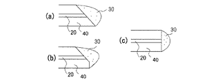
波長変換部材30の形状は特に限定されず、種々の形状とすることができる。例えば図2に示す形状のものである。図2(a)〜(c)は、波長変換部材の形状を示す概略断面図である。図2(a)はライトガイド先端部材40を斜めに切断しており、ライトガイド20の表面積を大きくし光取り出し効率を高めている。また、図2(b)はライトガイド先端部材40を斜めに切断しており、かつ先端部分を一部切断している。これによりライトガイド先端部材40と波長変換部材30との接触面積を大きくし密着性を高めている。図2(c)はライトガイド先端部材40を垂直に切断している。これにより波長変換部材30を効率よくライトガイド先端部材40に配置することができる。なお、ライトガイド先端部材40及びライトガイド20の端面全域を波長変換部材30が被覆するなど、できるだけ波長変換部材との接触面積を大きくすることが好ましい。
The shape of the
発光装置100から放出される光2は、白色であることが好ましいが、これに限定されない。また、良好な演色性を得るために、照射光の平均演色評価数(Ra)が70以上、さらに80以上となるような材料によって構成されることが好ましい。
The
ここで演色性とは、ある光源によって照明された物体の色の見え方を左右するその光源の性質を意味し、演色性が良好であるとは、一般に、太陽光によって照射された物体の色の見え方に限りなく近い性質を意味する((株)オーム社、「蛍光体ハンドブック」、p429参照)。演色性は、発光素子に、後述する蛍光物質層を組み合わせて用いることにより、良好にすることができる。また、平均演色評価数(Ra)とは、8種類の色票が試料光源及び基準光源それぞれによって照明された場合の色ズレの平均的な値を基礎として求められる。 Here, the color rendering property means the property of the light source that affects the appearance of the color of the object illuminated by a certain light source. Good color rendering property is generally the color of the object illuminated by sunlight. (Refer to Ohm Co., Ltd., “Phosphor Handbook”, p429). Color rendering properties can be improved by using a light emitting element in combination with a fluorescent material layer described later. The average color rendering index (Ra) is obtained based on an average value of color misregistration when eight types of color charts are illuminated by the sample light source and the reference light source, respectively.
得られる光の色調は、例えば、三原色(青色、緑色、赤色)の光を組み合わせることにより調整することができる。また、補色の関係にある青色と黄色、青緑色と赤色、緑色と赤色又は青紫色と黄緑色等の2色の光を組み合わせることによっても調整することができる。ここで補色とは、色度図で白色点をはさんで互いに反対側にある2つの色を意味する。なお、色調を調整するための各色の光は、その全てが必ずしも波長変換部材によって波長変換された光でなくてもよく、励起光源から得られた励起光自体を利用してもよい。また、明細書において、光の色と波長との関係は、JIS Z8110に準じる。 The color tone of the obtained light can be adjusted, for example, by combining light of three primary colors (blue, green, red). Further, it can be adjusted by combining two colors of light such as blue and yellow, blue-green and red, green and red, blue-purple and yellow-green, which are complementary colors. Here, the complementary color means two colors on the opposite sides of the white point in the chromaticity diagram. Note that the light of each color for adjusting the color tone does not necessarily have to be light whose wavelength has been converted by the wavelength conversion member, and excitation light itself obtained from an excitation light source may be used. In the specification, the relationship between the color of light and the wavelength conforms to JIS Z8110.
なお、波長変換部材30が混合されている保持部材は、さらに光拡散効果を高めるため、任意に、光拡散材を混合して用いてもよい。光拡散材は、外部から照射された光を反射、散乱及び/又は拡散等させることができる材料である。これにより、波長変換部材30に均一に励起光を当てることができると共に、混色も良好に成り色むらを低減することができる。また、保持部材に光拡散材を混合することにより、その粘度を調整することができるので、ライトガイド先端部材への波長変換部材の固定又は固着を容易にすることもできる。
In addition, in order to further enhance the light diffusion effect, the holding member in which the
波長変換部材30は、保持部材中に2種以上が均一に混合されていることが好ましいが、第1の波長変換部材を含有する単層の保持部材と、第2の波長変換部材を含有する単層の保持部材と、を積層させてもよい。さらに、第1の波長変換部材、第2の波長変換部材のいずれにも異なる波長変換部材を含有させてもよい。
Although it is preferable that two or more types of the
励起光源10を2つ以上組み合わせて用いる発光装置とする場合には、各励起光源からの励起光をライトガイドによって導出し、その光射出側を束ねて、全てについて一体的に単層又は複数層で、あるいは、部分的に一体的に単層又は複数層で、波長変換部材を配置してもよい。これにより、個々に波長変換部材を施す工程を簡略化することができる。
In the case of a light-emitting device using a combination of two or more
(ライトガイド先端部材)
ライトガイド20の先端、つまり励起光源10に接続されていない端部は、ライトガイド先端部材40によって支持されている。これにより、ライトガイド20の先端の発光効率、放熱等を向上させるとともに、発光装置としての組み立てが容易となる。ライトガイド先端部材40は、熱伝導性があり、波長変換後の光の少なくとも一部を反射するものであれば、特に限定されない。
(Light guide tip member)
The tip of the
ライトガイド先端部材40は、励起光及び/又は波長変換された光に対する反射率が高い、屈折率が高い、熱伝導性が高い、いずれかの材料又はこれらの性質を2種以上備える材料で構成することが好ましい。例えば、励起光及び/又は波長変換された光に対して80%以上の反射率、350〜500nm程度の光に対してn:1.4以上の屈折率及び/又は0.1W/m・℃以上の熱伝導性を有するものが好ましい。具体的にはAg、Al、ZrO2、Al2O3、AlN、ホウケイ酸ガラス、ステンレス鋼(SUS)、カーボン、銅、硫酸バリウム、ニッケル等が挙げられる。なかでも、ZrO2を用いた場合には、反射率が高く、ライトガイドが通るように加工することが容易であり、ステンレス鋼を用いた場合には、引っ張り強度を維持することが容易であるため、ZrO2、ステンレス鋼(例えば、SUS303等)で形成されていることが好ましい。
The light
(レンズ)
発光素子11と射出部12との間に、レンズ13を設けてもよい。
(lens)
A
レンズ13は、発光素子11から射出された光が、ライトガイド20の入射部に集光される限り、どのような形状でもよく、発光素子11と射出部12との間に、複数枚並べて配置してもよい。レンズは、無機ガラス、樹脂等により形成することができ、なかでも、無機ガラスが好ましい。励起光源10とライトガイド20との間にレンズ13を備え、レンズ13を介して励起光源10から射出された励起光をライトガイド20へ導出することができる。これにより励起光源10からの射出する励起光を集光させ、効率よくライトガイド20に導出することができる。
The
(発光装置の態様)
発光装置100は、1つの励起光源10と、一本のライトガイド20と、1つのライトガイド先端部材40と、波長変換部材30とから構成されていてもよいが、このユニットが少なくとも2つ以上組み合わせられて発光装置を構成していてもよい。ユニットの組み合わせ個数は、演色性と出力に応じて決定することができる。なお、この発光装置においては、上述したように、各ユニットの波長変換部材は複数のユニットにおいて一体的に形成されていてもよい。
(Mode of light emitting device)
The
本発明の発光装置の明るさは特に限定されるものではないが、例えば、各ユニットが120ルーメン/mm2程度以上の明るさを有していることが好ましい。 The brightness of the light emitting device of the present invention is not particularly limited. For example, it is preferable that each unit has a brightness of about 120 lumens / mm 2 or more.
(発光装置の用途)
発光装置100は、種々の用途に利用することができる。例えば、ディスプレイ、通常の照明器具、車両搭載用の照明(具体的には、ヘッドライト用、テールランプ用光源等)として利用してもよいし、内視鏡装置のように、生体内部を観察したり、観察しながら治療したりするための装置に利用してもよい。また、非常に狭い又は暗い空間、例えば、原子炉内部、遺跡の閉鎖空間等を観察したりするためのファイバースコープに利用してもよい。さらに、各種真空装置のチャンバ内など、電流の漏洩や発熱等を回避したい部材における光源として利用することもできる。加えて、点光源を要求する場所や光源の取り替えが困難な場所などで使用する発光装置として利用することができる。
(Use of light emitting device)
The
したがって、この発光装置は、撮像部材(つまり、光学像を電気信号に変換する電子部品(受光素子))、具体的には、CCD(charge-coupled device)、CMOS(CMOS image sensor)等を利用した撮像素子、電気信号を画像信号に変換する画像信号処理装置、電気信号又は測定値等を表示するインジケータ、画像信号を出力して画像を映し出すディスプレイ、各種の処理及び計算を行うコンピュータ等とともに使用することができる。特に、撮像部材として撮像素子を用いる場合には、被写体の光学像を、扱いやすいものとすることができる。 Therefore, this light emitting device uses an imaging member (that is, an electronic component (light receiving element) that converts an optical image into an electrical signal), specifically, a charge-coupled device (CCD), a CMOS image sensor (CMOS), or the like. Used with image sensors, image signal processing devices that convert electrical signals into image signals, indicators that display electrical signals or measured values, displays that output image signals and display images, computers that perform various processes and calculations, etc. can do. In particular, when an imaging element is used as the imaging member, the optical image of the subject can be handled easily.
例えば、受光素子(例えば、フォトダイオード等)は、発光装置と別体として設けてもよいが、励起光源10におけるレーザダイオードの近傍に、ライトガイド20の周辺に、或いはライトガイド先端部材40内のいずれに設けてもよい。これにより、受光素子によってレーザダイオードから発せられた光量を観測し、一定の光量以下の場合に、レーザダイオードに投入される電流を調整するなどして一定の光量を維持することができる。
For example, the light receiving element (for example, a photodiode) may be provided separately from the light emitting device, but in the vicinity of the laser diode in the
さらに、発光装置は、上述した発光装置により得られる可視光を利用し、例えば、発光装置に通信機能を付加することによりワイヤレス環境を構築することができ、可視光通信にも使用することができる。これにより、励起光源としてレーザダイオードを用いているために、数百MHzという変調速度を実現することができる。 Furthermore, the light-emitting device uses visible light obtained by the above-described light-emitting device. For example, a wireless environment can be constructed by adding a communication function to the light-emitting device, and can also be used for visible light communication. . Thereby, since a laser diode is used as an excitation light source, a modulation speed of several hundred MHz can be realized.
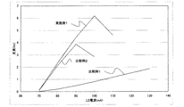
実施例1に係る発光装置は、励起光源10と、ライトガイド20と、波長変換部材30と、ライトガイド先端部材40とを備えて構成されている。図1に実施例1に係る発光装置の概略構成図を示す。図3は、第1の波長変換部材と第2の波長変換部材との発光スペクトルを示す図である。図4は、第1の波長変換部材と第2の波長変換部材との励起スペクトルを示す図である。図5は、第1の波長変換部材と第2の波長変換部材との反射スペクトルを示す図である。図6は、実施例1における発光装置の光束−投入電流の関係を示すグラフである。
The light emitting device according to the first embodiment includes an
励起光源10は、405nm近傍に発光ピーク波長を有するGaN系の半導体からなるレーザダイオードを発光素子11として用いた。発光素子11の前面には、発光素子11からの励起光1を集光するためのレンズ13を配置した。
As the
ライトガイド20は、その一端が、励起光源10の光の出射部12に接続されており、他端がライトガイド先端部材40に接続されている。ライトガイド20として、石英製のSI型114(μm:コア径)/125(μm:クラッド径)を用い、ライトガイドを支持するライトガイド先端部材40として、ジルコニア(ZrO2)製の直径0.7mmのものを用いた。
One end of the
波長変換部材30は、第1の波長変換部材と第2の波長変換部材とを樹脂中に均一に分散するように成型されて、ライトガイド先端部材40に取り付けられている。つまり、ライトガイド20とライトガイド先端部材40の双方の端面の全面にわたって、一層構造で波長変換部材30を配置させた。第1の波長変換部材は、緑色に発光するSrGa2S4:Euで表されるストロンチウムチオガレート系蛍光体を0.5g、第2の波長変換部材は、緑色に発光するLu3Al5O12:Ceで表されるアルミン酸塩系蛍光体を0.5gとを使用した。これらの波長変換部材をシリコーン樹脂2.2g中に均一になるまで混練し、ポッティングにより所定の形状を有する波長変換部材30を作製した。
The
なお、比較例1は波長変化部材をSrGa2S4:Euで表されるストロンチウムチオガレート系蛍光体のみとし、比較例2は波長変換部材をLu3Al5O12:Ceで表されるアルミン酸塩系蛍光体のみとしたこと以外、上記実施例1と同様の構成の発光装置を作製した。 In Comparative Example 1, the wavelength changing member is only a strontium thiogallate phosphor represented by SrGa 2 S 4 : Eu, and in Comparative Example 2, the wavelength converting member is aluminum represented by Lu 3 Al 5 O 12 : Ce. A light-emitting device having the same configuration as in Example 1 was prepared except that only the acid-based phosphor was used.
実施例1、比較例1及び2に係る発光装置において、励起光源を70〜130mAで駆動させて、特性を評価した。 In the light emitting devices according to Example 1 and Comparative Examples 1 and 2, the excitation light source was driven at 70 to 130 mA, and the characteristics were evaluated.
その結果、実施例1に係る発光装置は、比較例1及び2の発光装置に比較して光束の最高値が50%程度向上し、光出力が向上することが確認された。 As a result, it was confirmed that in the light emitting device according to Example 1, the maximum value of the luminous flux was improved by about 50% and the light output was improved as compared with the light emitting devices of Comparative Examples 1 and 2.
また、発光色の色度が比較例1の場合、色度座標(x,y)=(0.27,0.66)である。比較例2の場合、色度座標(x,y)=(0.3,0.56)である。よって、比較例2に係る発光装置は、色度座標y値が低い。また、比較例2に係る発光装置は、発光輝度が低い。これに対して、実施例1に係る発光装置は、色度座標(x,y)=(0.26,0.65)であり、色度座標y値が高く、発光輝度も高い。また、実施例1に係る第2の波長変換部材は、励起光源10からの光を積極的に光拡散している。
When the chromaticity of the emission color is Comparative Example 1, chromaticity coordinates (x, y) = (0.27, 0.66). In the case of Comparative Example 2, chromaticity coordinates (x, y) = (0.3, 0.56). Therefore, the light emitting device according to Comparative Example 2 has a low chromaticity coordinate y value. In addition, the light emitting device according to Comparative Example 2 has low light emission luminance. On the other hand, the light emitting device according to Example 1 has chromaticity coordinates (x, y) = (0.26, 0.65), a high chromaticity coordinate y value, and high light emission luminance. Further, the second wavelength conversion member according to the first embodiment actively diffuses the light from the
以上より、高輝度で、かつ色度座標y値が高い発光装置を提供することができる。 As described above, a light-emitting device with high luminance and high chromaticity coordinate y value can be provided.
実施例2に係る発光装置は、実施例1の保持部材である樹脂をガラスに変更した以外は同様の構成を採る。第1の波長変換部材であるチオガレート系蛍光体と第2の波長変換部材であるアルミン酸塩系蛍光体とを所定の組成を有するガラス中に分散させる。そのガラスを固体化して円柱状のものを製作する。この円柱状のガラスをライトガイド20の先端にライトガイド先端部材40を用いて取り付ける。これにより出力の高い光を放出する発光装置を提供することができる。
The light emitting device according to Example 2 has the same configuration except that the resin that is the holding member of Example 1 is changed to glass. A thiogallate phosphor as a first wavelength conversion member and an aluminate phosphor as a second wavelength conversion member are dispersed in glass having a predetermined composition. The glass is solidified to produce a cylindrical shape. The columnar glass is attached to the tip of the
本発明の発光装置は、照明器具、車両搭載用照明、ディスプレイ、インジケータ等に利用することができる。また、生体内部を撮像する内視鏡装置、狭い隙間及び暗い空間等を照明することができるファイバースコープ、電流の漏洩や発熱のない照明を必要とする各種工業用の装置等に利用することができる。 The light-emitting device of the present invention can be used for lighting fixtures, on-vehicle lighting, displays, indicators, and the like. It can also be used for endoscope devices that image the inside of living bodies, fiberscopes that can illuminate narrow gaps and dark spaces, and various industrial devices that require illumination without current leakage or heat generation. it can.
1 励起光
2 光
10 励起光源
11 発光素子
12 射出部
13 レンズ
20 ライトガイド
30 波長変換部材
40 ライトガイド先端部材
100 発光装置
DESCRIPTION OF
Claims (9)
該励起光源からの光を吸収して波長変換する波長変換部材と、を有する発光装置において、
該波長変換部材は、第1の波長変換部材と第2の波長変換部材とを少なくとも有し、
該第1の波長変換部材の発光ピーク波長と該第2の波長変換部材の発光ピーク波長とが30nm以内であり、
該励起光の発光ピーク波長における該第1の波長変換部材の励起スペクトルの相対発光効率が70%以上であり、且つ該励起光の発光ピーク波長における該第2の波長変換部材の励起スペクトルの相対発光効率が60%以下であり、
前記第2の波長変換部材が第1の波長変換部材に比べて前記励起光の発光ピーク波長における反射率が高いことを特徴とする発光装置。 An excitation light source that emits excitation light;
In a light emitting device having a wavelength conversion member that absorbs light from the excitation light source and converts the wavelength,
The wavelength conversion member has at least a first wavelength conversion member and a second wavelength conversion member,
The emission peak wavelength of the first wavelength conversion member and the emission peak wavelength of the second wavelength conversion member are within 30 nm,
The relative emission efficiency of the excitation spectrum of the first wavelength conversion member at the emission peak wavelength of the excitation light is 70% or more, and the relative excitation spectrum of the second wavelength conversion member at the emission peak wavelength of the excitation light. Luminous efficiency is 60% or less,
The light emitting device characterized in that the second wavelength conversion member has a higher reflectance at the emission peak wavelength of the excitation light than the first wavelength conversion member.
Priority Applications (1)
| Application Number | Priority Date | Filing Date | Title |
|---|---|---|---|
| JP2006228503A JP5135735B2 (en) | 2006-08-25 | 2006-08-25 | Light emitting device |
Applications Claiming Priority (1)
| Application Number | Priority Date | Filing Date | Title |
|---|---|---|---|
| JP2006228503A JP5135735B2 (en) | 2006-08-25 | 2006-08-25 | Light emitting device |
Publications (3)
| Publication Number | Publication Date |
|---|---|
| JP2008053477A JP2008053477A (en) | 2008-03-06 |
| JP2008053477A5 JP2008053477A5 (en) | 2009-10-01 |
| JP5135735B2 true JP5135735B2 (en) | 2013-02-06 |
Family
ID=39237237
Family Applications (1)
| Application Number | Title | Priority Date | Filing Date |
|---|---|---|---|
| JP2006228503A Active JP5135735B2 (en) | 2006-08-25 | 2006-08-25 | Light emitting device |
Country Status (1)
| Country | Link |
|---|---|
| JP (1) | JP5135735B2 (en) |
Families Citing this family (2)
| Publication number | Priority date | Publication date | Assignee | Title |
|---|---|---|---|---|
| US8833975B2 (en) | 2010-09-07 | 2014-09-16 | Sharp Kabushiki Kaisha | Light-emitting device, illuminating device, vehicle headlamp, and method for producing light-emitting device |
| JP5271349B2 (en) * | 2010-12-28 | 2013-08-21 | シャープ株式会社 | Light emitting device, lighting device, and vehicle headlamp |
Family Cites Families (3)
| Publication number | Priority date | Publication date | Assignee | Title |
|---|---|---|---|---|
| JP4250949B2 (en) * | 2001-11-01 | 2009-04-08 | 日亜化学工業株式会社 | Light emitting device and manufacturing method thereof |
| JP5302491B2 (en) * | 2003-12-22 | 2013-10-02 | 日亜化学工業株式会社 | LIGHT EMITTING DEVICE AND ENDOSCOPE DEVICE |
| JP4233466B2 (en) * | 2004-02-12 | 2009-03-04 | 三菱化学株式会社 | LIGHT EMITTING DEVICE, LIGHTING DEVICE, AND DISPLAY DEVICE |
-
2006
- 2006-08-25 JP JP2006228503A patent/JP5135735B2/en active Active
Also Published As
| Publication number | Publication date |
|---|---|
| JP2008053477A (en) | 2008-03-06 |
Similar Documents
| Publication | Publication Date | Title |
|---|---|---|
| JP4375270B2 (en) | Light emitting device | |
| JP4379530B2 (en) | Light emitting device | |
| JP4946188B2 (en) | Light emitting device | |
| EP1672755B1 (en) | Light emitting device | |
| US7433115B2 (en) | Light emitting device | |
| JP4720177B2 (en) | Light emitting device | |
| CN101532614B (en) | Light emitting device | |
| JP5858752B2 (en) | Endoscope light source device | |
| JP4729918B2 (en) | Light emitting device | |
| JP5526482B2 (en) | Driving method of light emitting device and light emitting device | |
| JP6438062B2 (en) | Endoscope system | |
| JP2008027947A (en) | Light emitting device | |
| JP4730227B2 (en) | Light emitting device | |
| JP5135735B2 (en) | Light emitting device | |
| JP5124908B2 (en) | Light emitting device | |
| JP6115967B2 (en) | Endoscope system | |
| WO2017195303A1 (en) | Illuminating device | |
| JP5561296B2 (en) | Light emitting device | |
| JP7117504B2 (en) | light emitting device | |
| JP2008053477A5 (en) | ||
| JP2013157166A (en) | Light source device and lighting system |
Legal Events
| Date | Code | Title | Description |
|---|---|---|---|
| A521 | Request for written amendment filed |
Free format text: JAPANESE INTERMEDIATE CODE: A523 Effective date: 20090818 |
|
| A621 | Written request for application examination |
Free format text: JAPANESE INTERMEDIATE CODE: A621 Effective date: 20090818 |
|
| A131 | Notification of reasons for refusal |
Free format text: JAPANESE INTERMEDIATE CODE: A131 Effective date: 20111026 |
|
| A977 | Report on retrieval |
Free format text: JAPANESE INTERMEDIATE CODE: A971007 Effective date: 20111026 |
|
| A521 | Request for written amendment filed |
Free format text: JAPANESE INTERMEDIATE CODE: A523 Effective date: 20111226 |
|
| A131 | Notification of reasons for refusal |
Free format text: JAPANESE INTERMEDIATE CODE: A131 Effective date: 20120731 |
|
| A521 | Request for written amendment filed |
Free format text: JAPANESE INTERMEDIATE CODE: A523 Effective date: 20120925 |
|
| TRDD | Decision of grant or rejection written | ||
| A01 | Written decision to grant a patent or to grant a registration (utility model) |
Free format text: JAPANESE INTERMEDIATE CODE: A01 Effective date: 20121016 |
|
| A01 | Written decision to grant a patent or to grant a registration (utility model) |
Free format text: JAPANESE INTERMEDIATE CODE: A01 |
|
| A61 | First payment of annual fees (during grant procedure) |
Free format text: JAPANESE INTERMEDIATE CODE: A61 Effective date: 20121029 |
|
| R150 | Certificate of patent or registration of utility model |
Ref document number: 5135735 Country of ref document: JP Free format text: JAPANESE INTERMEDIATE CODE: R150 Free format text: JAPANESE INTERMEDIATE CODE: R150 |
|
| FPAY | Renewal fee payment (event date is renewal date of database) |
Free format text: PAYMENT UNTIL: 20151122 Year of fee payment: 3 |
|
| R250 | Receipt of annual fees |
Free format text: JAPANESE INTERMEDIATE CODE: R250 |
|
| R250 | Receipt of annual fees |
Free format text: JAPANESE INTERMEDIATE CODE: R250 |
|
| R250 | Receipt of annual fees |
Free format text: JAPANESE INTERMEDIATE CODE: R250 |
|
| R250 | Receipt of annual fees |
Free format text: JAPANESE INTERMEDIATE CODE: R250 |
|
| R250 | Receipt of annual fees |
Free format text: JAPANESE INTERMEDIATE CODE: R250 |
|
| R250 | Receipt of annual fees |
Free format text: JAPANESE INTERMEDIATE CODE: R250 |
|
| R250 | Receipt of annual fees |
Free format text: JAPANESE INTERMEDIATE CODE: R250 |
|
| R250 | Receipt of annual fees |
Free format text: JAPANESE INTERMEDIATE CODE: R250 |