JP5130802B2 - Flush toilet - Google Patents
Flush toilet Download PDFInfo
- Publication number
- JP5130802B2 JP5130802B2 JP2007170591A JP2007170591A JP5130802B2 JP 5130802 B2 JP5130802 B2 JP 5130802B2 JP 2007170591 A JP2007170591 A JP 2007170591A JP 2007170591 A JP2007170591 A JP 2007170591A JP 5130802 B2 JP5130802 B2 JP 5130802B2
- Authority
- JP
- Japan
- Prior art keywords
- water
- storage tank
- water supply
- water storage
- supply pipe
- Prior art date
- Legal status (The legal status is an assumption and is not a legal conclusion. Google has not performed a legal analysis and makes no representation as to the accuracy of the status listed.)
- Active
Links
Images


Description
本発明は、水洗便器に係り、特に、便器本体とほぼ同じ高さ位置に設けられ便器本体の洗浄をするための洗浄水を貯水する貯水タンクを備える水洗便器に関する。 The present invention relates to a flush toilet, and more particularly to a flush toilet equipped with a water storage tank that is provided at substantially the same height as the toilet bowl and stores flush water for washing the toilet bowl.
近年、水洗大便器において、便器本体や貯水タンクの他に、ボウル部に流す洗浄水を加圧する加圧ポンプや、ジェット給水路側とリム給水路側とを切り替える切替弁などの機器、さらに、これらの作動状態を制御する基板や、温水洗浄便座などの電装品などが設けられるようになっている。 In recent years, in flush toilets, in addition to the toilet body and storage tank, devices such as a pressurizing pump that pressurizes the wash water that flows to the bowl, a switching valve that switches between the jet water supply side and the rim water supply side, and these A circuit board for controlling the operating state and electrical components such as a warm water washing toilet seat are provided.
しかしながら、上述した機械類、即ち、機器、基板及び電装品などは、腐食してしまうなど水分に弱く、給水路や貯水タンクなどから分離して設置するのが望ましい。ところが、特に、貯水タンクは、この貯水タンク内の水を給水路に供給する際に貯水タンク内に空気を取り込む必要があり、いずれかの部位に空気取り入れ口や通気管が設けられる。従って、その貯水タンク内の水の水蒸気などがその空気取り入れ口や通気管から外部に流出して結露し、機械類(機器、基板及び電装品など)を腐食させてしまうことがあった。 However, the above-described machinery, that is, equipment, substrates, electrical components, and the like are vulnerable to moisture such as corrosion, and are preferably installed separately from a water supply channel or a water storage tank. However, in particular, when the water storage tank supplies water in the water storage tank to the water supply channel, it is necessary to take air into the water storage tank, and an air intake port or a vent pipe is provided at any location. Therefore, water vapor or the like in the water storage tank flows out of the air intake port or the ventilation pipe to the outside and causes dew condensation, which may corrode machinery (equipment, board, electrical equipment, etc.).
また、貯水タンクにおいては、その貯水タンクに洗浄水を供給する給水管が負圧になる場合や、貯水タンク内へ水洗便器側からの加圧力が加わる場合に、その貯水タンク内の水がその給水管へと逆流し易くなる、という問題点もあった。 In addition, in a water storage tank, when the water supply pipe that supplies the wash water to the water storage tank has a negative pressure, or when pressure from the flush toilet is applied to the water storage tank, the water in the water storage tank There was also a problem that it was easy to flow back to the water supply pipe.
本発明は、上述した従来技術の問題点を解決するためになされたものであり、貯水タンク内の水蒸気が機械類を腐食させるなどの悪影響を及ぼすことを防止することが出来る水洗便器を提供することを目的とする。
また、本発明は、貯水タンク内の水がその貯水タンクへの給水管へと逆流することを防止することが出来る水洗便器を提供することを目的とする。
The present invention has been made to solve the above-described problems of the prior art, and provides a flush toilet capable of preventing the water vapor in the water storage tank from adversely affecting the machinery and the like. For the purpose.
Moreover, an object of this invention is to provide the flush toilet bowl which can prevent the water in a water storage tank flowing back to the water supply pipe | tube to the water storage tank.
上記の目的を達成するために本発明は、便器本体と、この便器本体とほぼ同じ高さ位置で且つ後方に設けられ便器本体の洗浄をするための洗浄水を貯水する貯水タンクと、この貯水タンク内の洗浄水を便器本体に圧送する加圧ポンプと、ジェット側へ洗浄水を供給するジェット側給水管と、リム側へ洗浄水を供給するリム側給水管と、貯水タンク及び加圧ポンプを覆うケーシングと、このケーシング内に収容された加圧ポンプなどの機械類を備える水洗便器であって、ジェット側又はリム側のいずれかの給水管に接続され、且つ常時大気に開放された大気開放部を備えたバキュームブレーカと、貯水タンクの上部にその一端部が接続され、その貯水タンク内と連通している通気管と、を有し、バキュームブレーカは、その上面をほぼ覆う天板部を有し、通気管の他端は、この天板部に向けて開口すると共に、バキュームブレーカの大気開放部と常時連通するように設けられていることを特徴としている。
このように構成された本発明においては、貯水タンクの上部にその貯水タンク内と連通する通気管の一端部が接続され、その通気管の他端が、バキュームブレーカの上面をほぼ覆う天板部に向けて開口するように設けられている。従って、貯水タンク内に発生した水蒸気が通気管を通ってバキュームブレーカの上面をほぼ覆う天板部に向けて排出されるので、水蒸気がその天井部に結露して水となって、通気管などを通して貯水タンク内に戻されたり、各給水管などに排出される。これらの結果、水分がケーシング内に収容された加圧ポンプなどの機械類に結露して、腐食させてしまうことを防止することが出来る。
In order to achieve the above object, the present invention provides a toilet body, a water storage tank for storing cleaning water provided at the rear and substantially at the same height as the toilet body for cleaning the toilet body, and the water storage A pressurizing pump that pumps cleaning water in the tank to the toilet body, a jet-side water supply pipe that supplies cleaning water to the jet side, a rim-side water supply pipe that supplies cleaning water to the rim side, a water storage tank, and a pressure pump A flush toilet equipped with a casing that covers and a machine such as a pressure pump accommodated in the casing, and is connected to a water supply pipe on either the jet side or the rim side and is always open to the atmosphere a vacuum breaker having an opening, is connected to one end portion to the upper portion of the water storage tank includes a vent tube in communication with the inside thereof water storage tank, a vacuum breaker is top plate covering the upper surface substantially Has the other end of the vent pipe is adapted to open toward the top plate portion, it is characterized in that is provided so as to constantly communicate with the atmosphere opening portion of the vacuum breaker.
In the present invention configured as described above, one end portion of a vent pipe communicating with the inside of the water storage tank is connected to the upper portion of the water tank, and the other end of the vent pipe substantially covers the upper surface of the vacuum breaker. It is provided so that it may open toward. Therefore, the water vapor generated in the water storage tank is discharged through the vent pipe toward the top plate part that almost covers the upper surface of the vacuum breaker. It is returned to the water storage tank through or discharged to each water supply pipe. As a result, it is possible to prevent moisture from being condensed and corroded by machinery such as a pressure pump housed in the casing.
また、本発明において、好ましくは、貯水タンクには、その上部に上方に突出した上部空間を有し、この上部空間には、貯水タンクへ水を供給する給水管の一端部が接続されていると共にその給水管の一端部と同じ高さか或いは上方に通気管の一端部が接続されている。
このように構成された本発明においては、上部空間が通気管により大気開放部と同様の作用をするため、貯水タンクへ水を供給する給水管に負圧が生じても、空気を吸うことになるので、貯水タンクからその給水管への水の逆流を防止することが出来る。
In the present invention, preferably, the water storage tank has an upper space protruding upward at an upper portion thereof, and one end portion of a water supply pipe for supplying water to the water storage tank is connected to the upper space. In addition, one end of the vent pipe is connected to the same height as or above the one end of the water supply pipe.
In the present invention configured as described above, the upper space acts by the vent pipe in the same manner as the open air portion, so even if negative pressure is generated in the water supply pipe for supplying water to the water storage tank, air is sucked in. Therefore, the reverse flow of water from the water storage tank to the water supply pipe can be prevented.
また、本発明において、好ましくは、上部空間には、その上部空間に接続された通気管の一端部及び/又は給水管の一端部に、それらの一端部を塞ぐことが出来る止水用の浮き球とそれを保持する籠部材が設けられている。
このように構成された本発明においては、通気管の一端部及び/又は給水管の一端部を塞ぐことが出来る止水用の浮き球とそれを保持する籠部材が設けられているので、貯水タンク内の水が上部空間まで上昇したときに、水が通気管及び/又は給水管に逆流することを防止することが出来る。従って、例えば便器が詰まった際にラバーカップでゼット口を押すことにより貯水タンク内の水に水圧がかかっても、汚水が通気管及び/又は給水管を逆流して、水道本管に入り込むことを防止することが出来る。
In the present invention, preferably, in the upper space, one end of the ventilation pipe connected to the upper space and / or one end of the water supply pipe is provided with a floating for water stop that can block the one end. A ball and a hook member for holding it are provided.
In the present invention configured as described above, a water-stopping floating ball that can block one end of the vent pipe and / or one end of the water supply pipe and a gutter member that holds it are provided. When the water in the tank rises to the upper space, the water can be prevented from flowing back to the vent pipe and / or the water supply pipe. Therefore, for example, when a toilet cup is clogged, the water in the water storage tank is pressurized by pushing the zette mouth with a rubber cup, so that sewage flows back through the ventilation pipe and / or water supply pipe and enters the water main. Can be prevented.
また、本発明において、好ましくは、さらに、ジェット側給水管及びリム側給水管への給水を切り替える給水路切替弁を有し、ジェット側給水管には、給水路切替弁と貯水タンクとの間の給水管が含まれ、バキュームブレーカは、この給水管に接続されている。
このように構成された本発明においては、このバキュームブレーカで結露した水分が給水管或いは通気管を通して貯水タンク内に戻される。
Further, in the present invention, preferably, it further includes a water supply path switching valve for switching the water supply to the jet side water supply pipe and the rim side water supply pipe, and the jet side water supply pipe has a space between the water supply path switching valve and the water storage tank. A water supply pipe is included, and a vacuum breaker is connected to the water supply pipe.
In the present invention configured as described above, the moisture condensed by the vacuum breaker is returned to the water storage tank through the water supply pipe or the vent pipe.
また、上記の目的を達成するために本発明は、便器本体と、この便器本体とほぼ同じ高さに設けられた貯水タンクと、この貯水タンク内の水を便器本体に圧送する加圧ポンプと、貯水タンク及び加圧ポンプを覆うケーシングとを備える水洗便器であって、貯水タンクの上部にその一端部が接続され、その貯水タンク内に水を供給する給水管と、この給水管に接続され、その上面をほぼ覆う天板部と、常時大気に開放された大気開放部と、を備えたバキュームブレーカと、貯水タンクの上部にその一端部が接続され、その貯水タンクの上部空間と連通している通気管と、を有し、貯水タンクの上部にそれぞれ接続された通気管の一端部及び/又は給水管の一端部には、それらの一端部を塞ぐことが出来る止水用の浮き球及びそれを保持する籠部材が設けられ、通気管の他端部は、バキュームブレーカの天板部に向けて開口すると共に、バキュームブレーカの大気開放部と常時連通するように設けられていることを特徴としている。
このように構成された本発明においては、貯水タンクの上部にその貯水タンク内と連通する通気管の一端部が接続され、その通気管の他端が、バキュームブレーカの上面をほぼ覆う天板部に向けて開口するように設けられている。従って、貯水タンク内に発生した水蒸気が通気管を通ってバキュームブレーカの上面をほぼ覆う天板部に向けて排出されるので、水蒸気がその天井部に結露して水となって、通気管などを通して貯水タンク内に戻されたり、各給水管などに排出される。さらに、通気管の一端部及び/又は給水管の一端部を塞ぐことが出来る止水用の浮き球とそれを保持する籠部材が設けられているので、貯水タンク内の水が上部空間まで上昇したときに、水が通気管及び/又は給水管に逆流することを防止することが出来る。
In order to achieve the above object, the present invention includes a toilet body, a water storage tank provided at substantially the same height as the toilet body, and a pressure pump that pumps water in the water storage tank to the toilet body. A flush toilet comprising a water tank and a casing covering the pressure pump, one end of which is connected to the upper part of the water tank, a water supply pipe for supplying water into the water storage tank, and a water supply pipe connected to the water supply pipe The vacuum breaker having a top plate that almost covers the upper surface, and an air release portion that is always open to the atmosphere, and one end of the vacuum breaker connected to the upper portion of the water storage tank communicates with the upper space of the water storage tank. And one end portion of the vent pipe and / or one end portion of the water supply pipe respectively connected to the upper part of the water storage tank, and a floating ball for water stop that can block the one end portion thereof And the buttocks that hold it Is provided, the other end of the vent tube is adapted to open toward the top plate of the vacuum breaker is characterized in that is provided so as to constantly communicate with the atmosphere opening portion of the vacuum breaker.
In the present invention configured as described above, one end portion of a vent pipe communicating with the inside of the water storage tank is connected to the upper portion of the water tank, and the other end of the vent pipe substantially covers the upper surface of the vacuum breaker. It is provided so that it may open toward. Therefore, the water vapor generated in the water storage tank is discharged through the vent pipe toward the top plate part that almost covers the upper surface of the vacuum breaker. It is returned to the water storage tank through or discharged to each water supply pipe. Furthermore, a water-stopping floating ball that can block one end of the aeration pipe and / or one end of the water supply pipe and a gutter member that holds it are provided, so that the water in the water storage tank rises to the upper space. In this case, it is possible to prevent water from flowing back into the vent pipe and / or the water supply pipe.
本発明によれば、貯水タンク内の水蒸気が機械類を腐食させるなどの悪影響を及ぼすことを防止することが出来る。また、貯水タンク内の水がその貯水タンクへの給水管へと逆流することを防止することが出来る。 According to the present invention, it is possible to prevent the water vapor in the water storage tank from adversely affecting the machinery. Further, it is possible to prevent the water in the water storage tank from flowing back to the water supply pipe to the water storage tank.
以下、添付図面を参照して、本発明の実施形態による水洗便器を説明する。
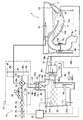
先ず、図1乃至図3により、本発明の実施形態による水洗大便器の構造を説明する。図1は、本発明の実施形態による水洗大便器の側面図であり、図2は図1に示す水洗大便器の平面図であり、図3は本発明の実施形態による水洗大便器の水路系統を示す全体構成図である。
Hereinafter, a flush toilet according to an embodiment of the present invention will be described with reference to the accompanying drawings.
First, the structure of a flush toilet according to an embodiment of the present invention will be described with reference to FIGS. 1 is a side view of a flush toilet according to an embodiment of the present invention, FIG. 2 is a plan view of the flush toilet shown in FIG. 1, and FIG. 3 is a channel system of the flush toilet according to an embodiment of the present invention. FIG.
図1及び図2に示すように、本発明の実施形態による水洗大便器1は、便器本体2と、この便器本体2の上面に配置された便座4と、便座4を覆うように配置されたカバー6と、便器本体の後方上部に配置された局部洗浄装置8と、を備えている。さらに、便器本体2の後方には、機能部10が配置されており、この機能部10はサイドパネル(ケーシング)11により覆われている。
As shown in FIGS. 1 and 2, the flush toilet 1 according to the embodiment of the present invention is disposed so as to cover the toilet body 2, the toilet seat 4 disposed on the upper surface of the toilet body 2, and the toilet seat 4. The
便器本体2には、汚物を受けるボウル部12と、このボウル部12の底部から延びる排水トラップ管路14と、排水トラップ管路14の下端に接続された配水管15と、ジェット吐水を行うジェット吐水口16と、リム吐水を行うリム吐水口18が形成されている。
ジェット吐水口16は、ボウル部12の底部に形成されており、排水トラップ管路14の入口に指向してほぼ水平に配置され、洗浄水を排水トラップ管路14に向けて吐水するようになっている。リム吐水口18は、ボウル部12の左側上部後方に形成されており、ボウル部12の上縁に沿って洗浄水を吐出するようになっている。
The toilet body 2 includes a
The
排水トラップ管路14は、入口部14aと、この入口部14aから上昇するトラップ上昇管14bと、このトラップ上昇管14bから下降するトラップ下降管14cとからなり、トラップ上昇管14bとトラップ下降管14cとの間が頂部14dとなっている。トラップ下降管14cの下端に上述した配水管15が接続されている。
The
本実施形態による水洗大便器1は、洗浄水を供給する水道に直結されており、水道の給水圧力によりリム吐水口18から洗浄水が吐出される。また、ジェット吐水に関しては、後述するように、機能部10に内蔵された貯水タンク20に貯水された洗浄水を加圧ポンプ22によって加圧して、大流量でジェット吐水口16から吐出させるようになっている。
The flush toilet 1 according to the present embodiment is directly connected to a water supply that supplies cleaning water, and the cleaning water is discharged from the
次に、図3により、本実施形態による水洗大便器1の機能部10を詳細に説明する。
図3に示すように、機能部10には、水道から洗浄水が供給される給水路24が設けられ、この給水路24には、上流側から、止水栓26、ストレーナ28、分岐金具30、定流量弁32、ダイヤフラム式の電磁開閉弁34、給水路切替弁36がそれぞれ設けられている。定流量弁32は、止水栓26、ストレーナ28、分岐金具30を介して流入した洗浄水を、所定の流量以下に絞るためのものである。
Next, the
As shown in FIG. 3, the
これらの定流量弁32、電磁開閉弁34、及び、給水路切替弁36は、図3に示すように、バルブユニット37として、一体的に組み立てられたものとなっている。また、給水路切替弁36の下流側には、リム吐水口18に洗浄水を供給するためのリム側給水路38、及び、貯水タンク20に洗浄水を供給するためのタンク側給水路40が接続されている。
The
ここで、定流量弁32を通過した洗浄水は、電磁開閉弁34に流入し、電磁開閉弁34を通過した洗浄水は、給水路切替弁36により、リム側であるリム給水路38からリム吐水口18へ、又は、タンク側であるタンク側給水路40から貯水タンク20に供給されるようになっている。給水路切替弁36は、リム側給水路38とタンク側給水路40の両方に同じタイミングで洗浄水を供給可能であって、リム側とタンク側への給水量の割合を任意に変更出来る切替弁である。
これらの電磁開閉弁34の開閉操作、及び、給水路切替弁36の切替操作は、機能部10のコントローラ62により制御される。
Here, the wash water that has passed through the
The opening / closing operation of the electromagnetic opening / closing
また、貯水タンク20の下部には、ジェット側給水路46が接続されており、このジェット側給水路46の下流端は、ジェット吐水口16に接続されている。また、ジェット側給水路46の途中に上述した加圧ポンプ22が設けられている。この加圧ポンプ22は、貯水タンク20に貯水された洗浄水を加圧して、ジェット吐水口16から吐出させるためのものである。加圧ポンプ22の回転数や作動時間等は、機能部10に設けられたコントローラ62により制御される。
A jet-side
ジェット側給水路46は、加圧ポンプ22より上流側の上流ジェット側給水路46aと下流側の下流ジェット側給水路46bとから構成されている。ここで、下流ジェット側給水路46bは、図3に示すように、先ず、加圧ポンプ22から上方に延び、大便器1のボウル部12の溜水面よりも上方に配管が配置され、その後、配管が下方に向けて延びて構成されている。このように上方に向けた凸型に形成されている下流ジェット側給水路46bにおいて、その凸型部分の最も高い部分である頂部46cは、貯水タンク20からジェット吐水口16に至るジェット側給水路46の中で最も高い部分になっている。
The jet-side
次に、上述したリム側給水路38には、リム吐水用バキュームブレーカ48が設けられており、給水路24に負圧が発生したときに洗浄水のリム吐出口18からの逆流を防止している。また、リム吐出用バキュームブレーカ48は、図3に示すように、ボウル部12の上端面よりも上方に配置され、これにより、逆流を確実に防止している。さらに、リム吐水用バキュームブレーカ48の大気開放部から溢れた洗浄水は、通気管(戻り管路)50を通って貯水タンク20に流入するようになっている。
タンク側給水路40にも、逆止弁であるバキュームブレーカ42が設けられており、洗浄水の貯水タンクからの逆流を防止している。
Next, the rim-side
The tank side
ここで、貯水タンク20は、密閉タイプの貯水タンクであり、タンク側給水路40と貯水タンク20との接続部80には、後述するようにボール式逆止弁43が設けられている。このボール式逆止弁43により、貯水タンク20が満水状態になった場合でも、ボール90が浮上して、タンク側給水路40との接続部を閉鎖するので、洗浄水がタンク側給水路40に逆流することがないようになっている。
同様に、通気管50と貯水タンク20の接続部82にも、後述するようにボール式逆止弁44が設けられており、貯水タンク20が満水状態となった場合でも、洗浄水が戻り管路50に逆流することはないようになっている。
Here, the
Similarly, a ball
さらに、ジェット側給水路46の上流ジェット側給水路46aには、逆止弁であるジェット吐水用フラッパー弁56及び水抜栓58が設けられている。これらのジェット吐水用フラッパー弁56及び水抜栓58は、加圧ポンプ22よりも下方の、貯水タンク20の下端部付近の高さに配置されている。このため、水抜栓58を開放することにより、メンテナンス時等に貯水タンク20内及び加圧ポンプ22内の洗浄水を排水することができるようになっている。
Furthermore, a jet water spouting
また、貯水タンク20と加圧ポンプ22の間にジェット吐水用フラッパー弁56を配置することにより、貯水タンク20内の水位が加圧ポンプ22の高さよりも低くなった場合に、洗浄水が加圧ポンプ22から貯水タンク20に逆流し、加圧ポンプ22内の洗浄水が抜け、加圧ポンプ22が空運転してしまうことを防止している。また、加圧ポンプ22の下方には、水受けトレイ60が配置されており、結露した水滴や漏水を受けるようになっている。
Further, by disposing the jet water spouting
貯水タンク20の内部には、上方フロートスイッチ64a、及び、下方フロートスイッチ64bが配置されている。上方フロートスイッチ64aは、貯水タンク20内の水位が通常使用時の満水位置(L1)に達するとオンに切り替わり、コントローラ62はこれを検知して、電磁開閉弁34を閉鎖させる。下方フロートスイッチ64bは、貯水タンク20内の水位が所定の水位(L3)まで低下するとオンに切り替わり、コントローラ62はこれを検知して、加圧ポンプ22を停止させる。
Inside the
さらに、貯水タンク20の上方フロートスイッチ64aよりも上方位置に、その一端70aが開口し、他端70bが下流ジェット側給水路64bに接続されたオーバーフロー流路70が設けられている。このオーバーフロー流路70には、逆止弁であるフラッパー弁72が取り付けられている。
このオーバーフロー流路70は、貯水タンク20において、水が開口70aより高くなるような場合、その貯水タンク20内の水をジェット側給水路46に逃がして、貯水タンク20から水が溢れ出すことがないようにするものである。
Further, an
When the water in the
また、このオーバーフロー流路70及びフラッパー弁72により、洗浄水のジェット吐水口16からの逆流を防止すると共に、これらの間の縁切りを行うことができるようになっている。また、オーバーフロー流路70の他端70bが、ボウル部12内の溜水の水位よりも上方に設けられているため、洗浄水のジェット吐水口16からの逆流をより確実に防止するようにしている。
Further, the
上述した電磁開閉弁34、給水路切替弁36、加圧ポンプ22などの動作内容を説明する。コントローラ62は、使用者による便器洗浄スイッチ(図示せず)の操作により、電磁開閉弁34、給水路切替弁36を作動させ、先ずリム吐水口18から吐水し、リム吐水を継続させながら、次に加圧ポンプ22を作動してジェット吐水口からの吐水を開始させて、サイホン作用を発生させてボウル部12の溜水を汚物と共に排出洗浄する。さらに、コントローラ62は、加圧ポンプ22の作動停止した後もリム吐水を継続してボウル部12に溜水を貯めて洗浄終了する。その洗浄終了後、給水路切替弁36を貯水タンク20側に切り替えて洗浄水を貯水タンク20に補給する。貯水タンク20内の水位が上昇し、上方フロートスイッチ64aが規定の貯水量を検出すると、コントローラ62は、電磁弁34を閉鎖して給水を停止する。
The operation contents of the electromagnetic on-off
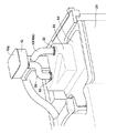
次に、図3乃至図6により、貯水タンク20の上部蓋構造を説明する。図4は、本発明の実施形態による貯水タンクの上部蓋を斜め上方から見た斜視図であり、図5は、本発明の実施形態による貯水タンクの上部蓋の裏側を斜め下方から見た斜視図であり、図6は、図4のVI-VI線に沿って見た上部蓋の断面図である。
図4及び図5に示すように、上部蓋部84は、平面視で貯水タンク20の外形と同じ形状に形成され、その周縁部がタンク本体に結合されている。この上部蓋部84には、上方に突出する上部突出部86が形成され、その内方の上部空間Sは、図3に示すように、満水位置L1より上方であり、空気で満たされている。
Next, the upper lid structure of the
As shown in FIGS. 4 and 5, the
ここで、図3に示すように、便器本体2の排水トラップ管路14が詰まってボウル部12内の水位が上昇した際、ジェット吐水用フラッパー弁56やオーバーフロー流路70のフラッパー弁72がゴミ噛み等によって正常に機能していないと、貯水タンク20の水位はボウル部12の上面から水が溢れる水位まで上昇する。従って、ボウル部12の上面とタンク側給水路40の吐水口80bとの距離が、所謂エアギャップと呼ばれるものであり、この距離を所定量(1インチ以上)確保することにより、貯水タンク20内の水が水道本管へ逆流することを防止することが可能である。
Here, as shown in FIG. 3, when the
しかし、図3に示すように、本実施形態の貯水タンク20においては、貯水タンク20の容積を少なくコンパクトに構成するために、上部突出部86内の上部空間Sは狭く、ボウル部12の上面とタンク側給水路40の吐水口80bとの鉛直方向における距離は所定量確保できているものの、上部突出部86の側壁とタンク側給水路40の吐水口80bとの距離が確保できていない。
However, as shown in FIG. 3, in the
ここで、水路系統の1次側であるタンク側給水路40が負圧になったときには、その接続部80の隣に、後述するようにバキュームブレーカ42の大気開放部Aへと接続された通気管50が設けられているので、タンク側給水路40は、貯水タンク20内の水を吸引するのではなく、その通気管50から空気を吸引するので、貯水タンク20内の水がタンク側給水路40に逆流することを防止することが出来る。
Here, when the tank-side
一方、便器詰まり時などに使用されるラバーカップ(図示せず)によりジェット吐水口16から貯水タンク20に水圧がかかったときには、ジェット吐水用フラッパー弁56やオーバーフロー流路70のフラッパー弁72がゴミ噛み等によって正常に機能していないとその水圧を受けて貯水タンク20内の水が上昇する。このような場合にタンク側給水路40に逆流することを防止するために設けられた、ボール式逆止弁43,44について説明する。図3乃至図5に示すように、上述した上部蓋部84の上部突出部86の上面には、タンク側給水路40が接続される接続部80、及び、通気管50が接続される接続部82が設けられている。接続部80では、タンク側給水路40が接続される中空円筒形の接続部材80aが設けられ、この接続部材80aには、吐水口80bが形成されている。接続部82では、通気管50(タンク側給水路のバキュームブレーカ42及びリム吐水用バキュームブレーカ48の大気開放部から溢れた洗浄水が貯水タンク20に流入するための戻り管路50)が接続される中空円筒形の接続部材82aが設けられ、この接続部材82aには、水蒸気や空気の出口82bが形成されている。本実施形態では、タンク側給水路40が接続される接続部80、及び、通気管50が接続される接続部82はほぼ同じ高さに配置されているが、タンク側給水路40が接続される接続部80(接続部材80a、吐出口80b)よりも、通気管50が接続される接続部82(接続部材82a、出口82b)の方が上方に配置されていても良い。
On the other hand, when water pressure is applied from the jet
図5及び図6に示すように、それぞれの接続部材80a、82aの下方には、内部が空気で満たされているボール(浮き球)90、92がそれぞれ設けられ、さらに、これらのボール90、92を保持する籠部材94、96が設けられている。上部突出部86内が空気で満たされている場合には、ボール90、92が籠部材94、96により受け止められて、各接続部材80a、80b(吐水口80b及び出口82b)が開放状態になっている。従って、タンク側給水路40の吐水口80bから水が吐水可能となり、また、水蒸気や空気の出口82bから水蒸気や空気が流れ出ることが可能になる。
As shown in FIGS. 5 and 6, balls (floating balls) 90 and 92 filled with air are provided below the
従って、便器詰まり時などに使用されるラバーカップ(図示せず)によりジェット吐水口16から貯水タンク20に水圧がかかって貯水タンク20内の水が上昇した場合、ボール90、92がそれぞれ貯水タンク20内の水を受けてボール90、92自身の浮力により浮き上がり、吐水口80b(接続部材80a)及び出口82b(接続部材82a)を塞いて、貯水タンク20内の水がタンク側給水路40及び通水路50に逆流するのを防止するようになっている。
Accordingly, when water pressure is applied to the
これらのような逆流防止の作用は、特に、上述したエアギャップが比較的小さい場合に有効である。即ち、貯水タンク20の大きさが、他の機器や、基板や、電装品などとの関係で比較的小さく形成される場合でも、有効に逆流を防止することが出来るからである。
Such a backflow prevention action is particularly effective when the above-described air gap is relatively small. That is, even when the size of the
次に、図7及び図8により、タンク側給水路のバキュームブレーカの構造及び各管の配管について説明する。図7は、本発明の実施形態によるバキュームブレーカの構造を示す断面図であり、図8は、本発明の実施形態によるバキュームブレーカ、タンク側給水管路及び通気管などを斜め上方から見た斜視図である。
先ず、図7に示すように、バキュームブレーカ42には、入水口42a、出水口42b及び大気開放口42cが形成されている。入水口42aには、タンク側給水路40の上流部40aが接続され、出水口42bには、タンク側給水路40の下流部40bが接続され、大気開放口42cは大気に開放されている。そして、この大気開放口42cは、バキュームブレーカコマ42fにより閉鎖されるようになっている。バキュームブレーカコマ42fは、鉛直方向に移動可能に配置され、ガイド部42dにより摺動可能になっている軸部42eを有する。
Next, the structure of the vacuum breaker of the tank side water supply channel and the piping of each pipe will be described with reference to FIGS. FIG. 7 is a cross-sectional view showing the structure of the vacuum breaker according to the embodiment of the present invention. FIG. 8 is a perspective view of the vacuum breaker, the tank-side water supply pipe, the vent pipe, and the like according to the embodiment of the present invention when viewed obliquely from above. FIG.
First, as shown in FIG. 7, the
使用時においては、入水口42aから洗浄水が流入すると、その水勢によりバキュームブレーカコマ42fが上方位置に移動され、大気開放口42cが閉鎖される。これにより、入水口42aから流入した洗浄水は、出水口42bから吐出される。さらに、入水口42aからの洗浄水の流入が停止されると、バキュームブレーカコマ42fは重力により下方位置に移動され、入水口42aが閉鎖される。また、出水口42bは大気開放口42cと連通する。なお、バキュームブレーカコマ42fが重力により下方位置に移動し入水口42aを閉鎖するが、本実施形態においては、バキュームブレーカコマ42fと入水口42aとの間に若干の隙間が生じるようになっている。従って、一次側であるタンク側給水路40の上流部40aが負圧になっても、そのような隙間から空気を吸い込むことによって、タンク側給水路40の下流部40bの側からの水の逆流を防止することが出来る。また、このような隙間によってバキュームブレーカ42内に溢れた水を一次側であるタンク側給水路40の上流部40aに戻すことも可能である。
In use, when washing water flows from the
次に、バキュームブレーカ42には通気管取付口42hが形成されており、この通気管取付口42hに、通気管50が取り付けられている。タンク側給水路のバキュームブレーカ42の大気開放部Aから溢れた洗浄水は、戻り管路50を通って貯水タンク20に流入するようになっている。
次に、図7及び図8に示すように、バキュームブレーカ42には、バキュームブレーカ天板部42gが取り付けられている。このバキュームブレーカ天板部42gは、バキュームブレーカ42の大気開放部Aをほぼ覆うように設けられているが、その周囲にバキュームブレーカ本体と若干の隙間を有しており、大気に開放されている。
Next, the
Next, as shown in FIGS. 7 and 8, a vacuum breaker top plate portion 42 g is attached to the
ここで、上述した通気管取付口42h及びその取付口42h近傍における通気管50は、バキュームブレーカ天板部42gに向けて延びている。従って、貯水タンク20から通気管50を通って吐出される水蒸気や空気は、先ず、バキュームブレーカ天板部42gに向けて流出して、バキュームブレーカ天板部42gに当たるようになっている。その結果、水蒸気は、バキュームブレーカ天板部42gで結露して、バキュームブレーカの大気開放部A内に溜まり、この溜まった水は、再び通気管50を通って、或いは、タンク側給水路40の下流部40bを通って、再び、貯水タンク20内へと戻るようになる。
これにより、水蒸気が貯水タンク20から抜け出てしまい、他の機器や基板、特に温水洗浄便座などの電装品に水分が付着して腐食してしまうなどの問題を防止することが出来る。
なお、本実施形態では、水蒸気を結露させる天板部として、タンク側給水路のバキュームブレーカ42のものを利用しているが、リム吐水用バキュームブレーカ48の天板部を利用しても良い。
Here, the vent
As a result, it is possible to prevent a problem that water vapor escapes from the
In the present embodiment, the top plate portion of the
1 水洗大便器
2 便器本体
12 ボウル部
14 排水トラップ管路
16 ジェット吐水口
18 リム吐水口
20 貯水タンク
22 加圧ポンプ
24 給水路
38 リム側給水路
40 タンク側給水路
42 タンク側給水路のバキュームブレーカ
42g バキュームブレーカ天板部
42h 通気管取付口
46 ジェット側給水路
46a 上流ジェット側給水路
46b 下流ジェット側給水路
43、44 ボール式逆止弁
50 通気管(戻り管路)
56 ジェット吐水用フラッパー弁
64a 上方フロートスイッチ
64b 下方フロートスイッチ
70 オーバーフロー流路
72 フラッパー弁
80 タンク側給水路と貯水タンクとの接続部
80a 接続部材
80b 吐水口
82 戻り管路(通気管)と貯水タンクの接続部
82a 接続部材
82b 出口
86 貯水タンクの上方突出部
90、92 ボール(浮き球)
94、96 籠部材
A タンク側給水路のバキュームブレーカの大気開放部
S 貯水タンクの上方突出部の上部空間
DESCRIPTION OF SYMBOLS 1 Flush toilet 2
56 Jet water spouting
94, 96 籠 Member A Air release part S of vacuum breaker of tank side water supply channel S Upper space of upward projecting part of water storage tank
Claims (5)
上記ジェット側又は上記リム側のいずれかの給水管に接続され、且つ常時大気に開放された大気開放部を備えたバキュームブレーカと、
上記貯水タンクの上部にその一端部が接続され、その貯水タンク内と連通している通気管と、を有し、
上記バキュームブレーカは、その上面をほぼ覆う天板部を有し、上記通気管の他端は、この天板部に向けて開口すると共に、上記バキュームブレーカの大気開放部と常時連通するように設けられていることを特徴とする水洗便器。 A toilet body, a water storage tank that is provided at the rear of the toilet body and stores cleaning water for cleaning the toilet body, and the wash water in the water storage tank is pumped to the toilet body. A pressure pump, a jet-side water supply pipe for supplying cleaning water to the jet side, a rim-side water supply pipe for supplying cleaning water to the rim side, a casing covering the water storage tank and the pressure pump, and a casing A flush toilet equipped with machinery such as the pressurized pump accommodated therein,
A vacuum breaker connected to the water supply pipe on either the jet side or the rim side and provided with an air release portion that is always open to the atmosphere ;
One end of the water storage tank is connected to the upper part of the water storage tank, and a vent pipe communicated with the water storage tank.
The vacuum breaker has a top plate part that substantially covers the upper surface thereof, and the other end of the vent pipe opens toward the top plate part, and is provided so as to always communicate with the atmosphere opening part of the vacuum breaker. A flush toilet characterized by being made.
この上部空間には、上記貯水タンクへ水を供給する給水管の一端部が接続されていると共にその給水管の一端部と同じ高さか或いは上方に上記通気管の一端部が接続されている請求項1に記載の水洗便器。 The water storage tank has an upper space protruding upward at the upper part thereof,
One end of a water supply pipe for supplying water to the water storage tank is connected to the upper space, and one end of the vent pipe is connected to the same height as or above the one end of the water supply pipe. The flush toilet according to Item 1.
上記ジェット側給水管には、上記給水路切替弁と上記貯水タンクとの間の給水管が含まれ、上記バキュームブレーカは、この給水管に接続されている請求項1乃至3のいずれか1項に記載の水洗便器。 Furthermore, it has a water supply path switching valve for switching the water supply to the jet side water supply pipe and the rim side water supply pipe,
The jet-side water supply pipe includes a water supply pipe between the water supply path switching valve and the water storage tank, and the vacuum breaker is connected to the water supply pipe. The flush toilet according to.
上記貯水タンクの上部にその一端部が接続され、その貯水タンク内に水を供給する給水管と、
この給水管に接続され、その上面をほぼ覆う天板部と、常時大気に開放された大気開放部と、を備えたバキュームブレーカと、
上記貯水タンクの上部にその一端部が接続され、その貯水タンクの上部空間と連通している通気管と、を有し、
上記貯水タンクの上部にそれぞれ接続された上記通気管の一端部及び/又は上記給水管の一端部には、それらの一端部を塞ぐことが出来る止水用の浮き球及びそれを保持する籠部材が設けられ、上記通気管の他端部は、上記バキュームブレーカの天板部に向けて開口すると共に、上記バキュームブレーカの大気開放部と常時連通するように設けられていることを特徴とする水洗便器。 A toilet body, a water storage tank provided at substantially the same height as the toilet body, a pressure pump that pumps water in the water storage tank to the toilet body, and a casing that covers the water storage tank and the pressure pump. A flush toilet comprising
One end of the water storage tank is connected to the water tank, and a water supply pipe for supplying water into the water storage tank;
A vacuum breaker that is connected to the water supply pipe and substantially covers the top surface thereof , and an air release part that is always open to the atmosphere ;
One end of which is connected to the upper part of the water tank, and has a vent pipe communicating with the upper space of the water tank,
One end of the vent pipe and / or one end of the water supply pipe respectively connected to the upper part of the water storage tank, a floating ball for stopping water that can close the one end, and a gutter member that holds the ball is provided, the other end of the vent tube is washed with water, characterized in that said toward the top plate of the vacuum breaker while opening is provided so as to be always communicated with the atmosphere opening portion of the vacuum breaker Toilet bowl.
Priority Applications (1)
| Application Number | Priority Date | Filing Date | Title |
|---|---|---|---|
| JP2007170591A JP5130802B2 (en) | 2007-06-28 | 2007-06-28 | Flush toilet |
Applications Claiming Priority (1)
| Application Number | Priority Date | Filing Date | Title |
|---|---|---|---|
| JP2007170591A JP5130802B2 (en) | 2007-06-28 | 2007-06-28 | Flush toilet |
Publications (2)
| Publication Number | Publication Date |
|---|---|
| JP2009007846A JP2009007846A (en) | 2009-01-15 |
| JP5130802B2 true JP5130802B2 (en) | 2013-01-30 |
Family
ID=40323196
Family Applications (1)
| Application Number | Title | Priority Date | Filing Date |
|---|---|---|---|
| JP2007170591A Active JP5130802B2 (en) | 2007-06-28 | 2007-06-28 | Flush toilet |
Country Status (1)
| Country | Link |
|---|---|
| JP (1) | JP5130802B2 (en) |
Families Citing this family (10)
| Publication number | Priority date | Publication date | Assignee | Title |
|---|---|---|---|---|
| JP5818010B2 (en) * | 2012-03-29 | 2015-11-18 | Toto株式会社 | Wash water supply device, wash water tank device provided with this wash water supply device, and flush toilet equipped with this wash water tank device |
| CN203200865U (en) * | 2013-01-28 | 2013-09-18 | 杜拉维特卫浴科技(上海)有限公司 | Automatic flushing system of toilet and electronic toilet |
| JP6456706B2 (en) * | 2015-01-30 | 2019-01-23 | 株式会社Lixil | Vacuum breaker and dirty logistics unit comprising the same |
| JP6685505B2 (en) * | 2016-03-30 | 2020-04-22 | Toto株式会社 | Water storage tank and flush toilet equipped with the water storage tank |
| JP6771742B2 (en) * | 2016-11-14 | 2020-10-21 | Toto株式会社 | Flush toilet |
| JP6891495B2 (en) * | 2017-01-06 | 2021-06-18 | Toto株式会社 | Washing water supply device and flushing toilet |
| JP7007633B2 (en) * | 2017-08-17 | 2022-01-24 | Toto株式会社 | Water supply valve device |
| JP2020186596A (en) * | 2019-05-16 | 2020-11-19 | Toto株式会社 | Water closet |
| JP2020186595A (en) * | 2019-05-16 | 2020-11-19 | Toto株式会社 | Water closet |
| JP7450360B2 (en) * | 2019-10-15 | 2024-03-15 | 株式会社Lixil | toilet device |
Family Cites Families (3)
| Publication number | Priority date | Publication date | Assignee | Title |
|---|---|---|---|---|
| JPS5951874U (en) * | 1982-09-25 | 1984-04-05 | アイシン精機株式会社 | water tank |
| JP4315029B2 (en) * | 2004-03-16 | 2009-08-19 | Toto株式会社 | Flush toilet |
| JP4390635B2 (en) * | 2004-06-11 | 2009-12-24 | 弘樹 山口 | Negative pressure breaker for water supply equipment |
-
2007
- 2007-06-28 JP JP2007170591A patent/JP5130802B2/en active Active
Also Published As
| Publication number | Publication date |
|---|---|
| JP2009007846A (en) | 2009-01-15 |
Similar Documents
| Publication | Publication Date | Title |
|---|---|---|
| JP5130802B2 (en) | Flush toilet | |
| JP5013316B2 (en) | Flush toilet | |
| JP5180295B2 (en) | Western-style toilet with an overflow prevention auxiliary tank | |
| KR20090096686A (en) | Flush toilet device | |
| JP5051611B2 (en) | Flush toilet | |
| JP4958070B2 (en) | Flush toilet | |
| JP5131633B2 (en) | Flush toilet | |
| JP5428462B2 (en) | Flush toilet | |
| JP2008240402A (en) | Western-style water closet | |
| JP5234484B2 (en) | Air bleed structure of flush toilet | |
| JP2010236201A (en) | Flush toilet bowl | |
| JP4941892B2 (en) | Flush toilet | |
| JP5146918B2 (en) | Toilet equipment | |
| JP6685505B2 (en) | Water storage tank and flush toilet equipped with the water storage tank | |
| JP2002201690A (en) | Trap device with auxiliary seal water supply mechanism | |
| JP4941889B2 (en) | Flush toilet | |
| JP2018100574A (en) | Water closet | |
| JP6891495B2 (en) | Washing water supply device and flushing toilet | |
| TW201430193A (en) | Automatic flushing system for toilet and electronic bidet toilet having the same | |
| EP2130982A1 (en) | Toilet installation, toilet tank and method of unclogging | |
| JP4517848B2 (en) | Toilet bowl cleaning device | |
| JP2015040413A (en) | Drain piping structure | |
| JP2008248637A (en) | Flush toilet bowl | |
| JP6771742B2 (en) | Flush toilet | |
| JP5007943B2 (en) | Flush toilet |
Legal Events
| Date | Code | Title | Description |
|---|---|---|---|
| A621 | Written request for application examination |
Free format text: JAPANESE INTERMEDIATE CODE: A621 Effective date: 20100324 |
|
| A977 | Report on retrieval |
Free format text: JAPANESE INTERMEDIATE CODE: A971007 Effective date: 20120217 |
|
| A131 | Notification of reasons for refusal |
Free format text: JAPANESE INTERMEDIATE CODE: A131 Effective date: 20120227 |
|
| A521 | Written amendment |
Free format text: JAPANESE INTERMEDIATE CODE: A523 Effective date: 20120425 |
|
| TRDD | Decision of grant or rejection written | ||
| A01 | Written decision to grant a patent or to grant a registration (utility model) |
Free format text: JAPANESE INTERMEDIATE CODE: A01 Effective date: 20121009 |
|
| A01 | Written decision to grant a patent or to grant a registration (utility model) |
Free format text: JAPANESE INTERMEDIATE CODE: A01 |
|
| A61 | First payment of annual fees (during grant procedure) |
Free format text: JAPANESE INTERMEDIATE CODE: A61 Effective date: 20121022 |
|
| FPAY | Renewal fee payment (event date is renewal date of database) |
Free format text: PAYMENT UNTIL: 20151116 Year of fee payment: 3 |
|
| R150 | Certificate of patent or registration of utility model |
Free format text: JAPANESE INTERMEDIATE CODE: R150 Ref document number: 5130802 Country of ref document: JP Free format text: JAPANESE INTERMEDIATE CODE: R150 |