JP5129246B2 - Oral devices for the treatment of snoring and sleep apnea - Google Patents
Oral devices for the treatment of snoring and sleep apnea Download PDFInfo
- Publication number
- JP5129246B2 JP5129246B2 JP2009515549A JP2009515549A JP5129246B2 JP 5129246 B2 JP5129246 B2 JP 5129246B2 JP 2009515549 A JP2009515549 A JP 2009515549A JP 2009515549 A JP2009515549 A JP 2009515549A JP 5129246 B2 JP5129246 B2 JP 5129246B2
- Authority
- JP
- Japan
- Prior art keywords
- tray
- user
- moldable material
- dentition
- support member
- Prior art date
- Legal status (The legal status is an assumption and is not a legal conclusion. Google has not performed a legal analysis and makes no representation as to the accuracy of the status listed.)
- Expired - Fee Related
Links
- 201000002859 sleep apnea Diseases 0.000 title description 7
- 238000011282 treatment Methods 0.000 title description 5
- 206010041235 Snoring Diseases 0.000 title description 4
- 239000000463 material Substances 0.000 claims description 114
- 210000004513 dentition Anatomy 0.000 claims description 80
- 230000036346 tooth eruption Effects 0.000 claims description 80
- 239000000853 adhesive Substances 0.000 claims description 22
- 230000001070 adhesive effect Effects 0.000 claims description 22
- 210000003205 muscle Anatomy 0.000 claims description 7
- 230000000638 stimulation Effects 0.000 claims description 7
- 230000000694 effects Effects 0.000 claims description 6
- 238000000034 method Methods 0.000 description 35
- 230000008569 process Effects 0.000 description 28
- 238000005266 casting Methods 0.000 description 15
- 210000000214 mouth Anatomy 0.000 description 15
- 238000010438 heat treatment Methods 0.000 description 13
- 230000000670 limiting effect Effects 0.000 description 12
- 229920001610 polycaprolactone Polymers 0.000 description 12
- 230000013011 mating Effects 0.000 description 11
- 239000004632 polycaprolactone Substances 0.000 description 9
- XLYOFNOQVPJJNP-UHFFFAOYSA-N water Substances O XLYOFNOQVPJJNP-UHFFFAOYSA-N 0.000 description 6
- 238000009434 installation Methods 0.000 description 5
- 238000012806 monitoring device Methods 0.000 description 5
- 238000001816 cooling Methods 0.000 description 4
- 210000002455 dental arch Anatomy 0.000 description 4
- 230000007246 mechanism Effects 0.000 description 4
- 208000001797 obstructive sleep apnea Diseases 0.000 description 4
- 206010061274 Malocclusion Diseases 0.000 description 3
- 230000006870 function Effects 0.000 description 3
- 238000003780 insertion Methods 0.000 description 3
- 230000037431 insertion Effects 0.000 description 3
- 238000012544 monitoring process Methods 0.000 description 3
- 230000029058 respiratory gaseous exchange Effects 0.000 description 3
- 241000282465 Canis Species 0.000 description 2
- CURLTUGMZLYLDI-UHFFFAOYSA-N Carbon dioxide Chemical compound O=C=O CURLTUGMZLYLDI-UHFFFAOYSA-N 0.000 description 2
- 229920003232 aliphatic polyester Polymers 0.000 description 2
- 208000030303 breathing problems Diseases 0.000 description 2
- DQXBYHZEEUGOBF-UHFFFAOYSA-N but-3-enoic acid;ethene Chemical compound C=C.OC(=O)CC=C DQXBYHZEEUGOBF-UHFFFAOYSA-N 0.000 description 2
- 229910052799 carbon Inorganic materials 0.000 description 2
- 230000003247 decreasing effect Effects 0.000 description 2
- 239000005038 ethylene vinyl acetate Substances 0.000 description 2
- 239000007789 gas Substances 0.000 description 2
- 210000001847 jaw Anatomy 0.000 description 2
- 210000004373 mandible Anatomy 0.000 description 2
- 210000002050 maxilla Anatomy 0.000 description 2
- 229920001200 poly(ethylene-vinyl acetate) Polymers 0.000 description 2
- 229920000515 polycarbonate Polymers 0.000 description 2
- 239000004417 polycarbonate Substances 0.000 description 2
- 229920005668 polycarbonate resin Polymers 0.000 description 2
- 239000004431 polycarbonate resin Substances 0.000 description 2
- 230000000241 respiratory effect Effects 0.000 description 2
- 230000000717 retained effect Effects 0.000 description 2
- 210000004872 soft tissue Anatomy 0.000 description 2
- 229920001169 thermoplastic Polymers 0.000 description 2
- 239000004416 thermosoftening plastic Substances 0.000 description 2
- -1 Elbax Chemical compound 0.000 description 1
- 229920003345 Elvax® Polymers 0.000 description 1
- 206010019280 Heart failures Diseases 0.000 description 1
- 206010020591 Hypercapnia Diseases 0.000 description 1
- 206010020772 Hypertension Diseases 0.000 description 1
- 206010021143 Hypoxia Diseases 0.000 description 1
- 230000002730 additional effect Effects 0.000 description 1
- 230000002411 adverse Effects 0.000 description 1
- 239000002969 artificial stone Substances 0.000 description 1
- QVGXLLKOCUKJST-UHFFFAOYSA-N atomic oxygen Chemical compound [O] QVGXLLKOCUKJST-UHFFFAOYSA-N 0.000 description 1
- 239000008280 blood Substances 0.000 description 1
- 210000004369 blood Anatomy 0.000 description 1
- 206010006514 bruxism Diseases 0.000 description 1
- 229910002092 carbon dioxide Inorganic materials 0.000 description 1
- 239000001569 carbon dioxide Substances 0.000 description 1
- 206010008118 cerebral infarction Diseases 0.000 description 1
- 208000026106 cerebrovascular disease Diseases 0.000 description 1
- 229920006026 co-polymeric resin Polymers 0.000 description 1
- 238000010276 construction Methods 0.000 description 1
- 238000007334 copolymerization reaction Methods 0.000 description 1
- 230000008878 coupling Effects 0.000 description 1
- 238000010168 coupling process Methods 0.000 description 1
- 238000005859 coupling reaction Methods 0.000 description 1
- 238000009795 derivation Methods 0.000 description 1
- 208000037265 diseases, disorders, signs and symptoms Diseases 0.000 description 1
- 208000035475 disorder Diseases 0.000 description 1
- 239000013536 elastomeric material Substances 0.000 description 1
- 239000010440 gypsum Substances 0.000 description 1
- 229910052602 gypsum Inorganic materials 0.000 description 1
- 230000005802 health problem Effects 0.000 description 1
- 208000018875 hypoxemia Diseases 0.000 description 1
- 238000007373 indentation Methods 0.000 description 1
- 230000014759 maintenance of location Effects 0.000 description 1
- 238000004519 manufacturing process Methods 0.000 description 1
- 210000001352 masseter muscle Anatomy 0.000 description 1
- 230000004048 modification Effects 0.000 description 1
- 238000012986 modification Methods 0.000 description 1
- 239000012778 molding material Substances 0.000 description 1
- 230000004118 muscle contraction Effects 0.000 description 1
- 229910052760 oxygen Inorganic materials 0.000 description 1
- 239000001301 oxygen Substances 0.000 description 1
- 229920003023 plastic Polymers 0.000 description 1
- 239000004033 plastic Substances 0.000 description 1
- 229920005989 resin Polymers 0.000 description 1
- 239000011347 resin Substances 0.000 description 1
- 210000002345 respiratory system Anatomy 0.000 description 1
- 208000023504 respiratory system disease Diseases 0.000 description 1
- 208000024891 symptom Diseases 0.000 description 1
- 238000002560 therapeutic procedure Methods 0.000 description 1
Images


Classifications
-
- A—HUMAN NECESSITIES
- A61—MEDICAL OR VETERINARY SCIENCE; HYGIENE
- A61F—FILTERS IMPLANTABLE INTO BLOOD VESSELS; PROSTHESES; DEVICES PROVIDING PATENCY TO, OR PREVENTING COLLAPSING OF, TUBULAR STRUCTURES OF THE BODY, e.g. STENTS; ORTHOPAEDIC, NURSING OR CONTRACEPTIVE DEVICES; FOMENTATION; TREATMENT OR PROTECTION OF EYES OR EARS; BANDAGES, DRESSINGS OR ABSORBENT PADS; FIRST-AID KITS
- A61F5/00—Orthopaedic methods or devices for non-surgical treatment of bones or joints; Nursing devices; Anti-rape devices
- A61F5/56—Devices for preventing snoring
- A61F5/566—Intra-oral devices
-
- B—PERFORMING OPERATIONS; TRANSPORTING
- B29—WORKING OF PLASTICS; WORKING OF SUBSTANCES IN A PLASTIC STATE IN GENERAL
- B29C—SHAPING OR JOINING OF PLASTICS; SHAPING OF MATERIAL IN A PLASTIC STATE, NOT OTHERWISE PROVIDED FOR; AFTER-TREATMENT OF THE SHAPED PRODUCTS, e.g. REPAIRING
- B29C39/00—Shaping by casting, i.e. introducing the moulding material into a mould or between confining surfaces without significant moulding pressure; Apparatus therefor
- B29C39/22—Component parts, details or accessories; Auxiliary operations
- B29C39/38—Heating or cooling
-
- B—PERFORMING OPERATIONS; TRANSPORTING
- B29—WORKING OF PLASTICS; WORKING OF SUBSTANCES IN A PLASTIC STATE IN GENERAL
- B29C—SHAPING OR JOINING OF PLASTICS; SHAPING OF MATERIAL IN A PLASTIC STATE, NOT OTHERWISE PROVIDED FOR; AFTER-TREATMENT OF THE SHAPED PRODUCTS, e.g. REPAIRING
- B29C33/00—Moulds or cores; Details thereof or accessories therefor
- B29C33/38—Moulds or cores; Details thereof or accessories therefor characterised by the material or the manufacturing process
- B29C33/3842—Manufacturing moulds, e.g. shaping the mould surface by machining
- B29C33/3857—Manufacturing moulds, e.g. shaping the mould surface by machining by making impressions of one or more parts of models, e.g. shaped articles and including possible subsequent assembly of the parts
-
- B—PERFORMING OPERATIONS; TRANSPORTING
- B29—WORKING OF PLASTICS; WORKING OF SUBSTANCES IN A PLASTIC STATE IN GENERAL
- B29C—SHAPING OR JOINING OF PLASTICS; SHAPING OF MATERIAL IN A PLASTIC STATE, NOT OTHERWISE PROVIDED FOR; AFTER-TREATMENT OF THE SHAPED PRODUCTS, e.g. REPAIRING
- B29C39/00—Shaping by casting, i.e. introducing the moulding material into a mould or between confining surfaces without significant moulding pressure; Apparatus therefor
- B29C39/003—Shaping by casting, i.e. introducing the moulding material into a mould or between confining surfaces without significant moulding pressure; Apparatus therefor characterised by the choice of material
-
- B—PERFORMING OPERATIONS; TRANSPORTING
- B29—WORKING OF PLASTICS; WORKING OF SUBSTANCES IN A PLASTIC STATE IN GENERAL
- B29C—SHAPING OR JOINING OF PLASTICS; SHAPING OF MATERIAL IN A PLASTIC STATE, NOT OTHERWISE PROVIDED FOR; AFTER-TREATMENT OF THE SHAPED PRODUCTS, e.g. REPAIRING
- B29C39/00—Shaping by casting, i.e. introducing the moulding material into a mould or between confining surfaces without significant moulding pressure; Apparatus therefor
- B29C39/02—Shaping by casting, i.e. introducing the moulding material into a mould or between confining surfaces without significant moulding pressure; Apparatus therefor for making articles of definite length, i.e. discrete articles
-
- B—PERFORMING OPERATIONS; TRANSPORTING
- B29—WORKING OF PLASTICS; WORKING OF SUBSTANCES IN A PLASTIC STATE IN GENERAL
- B29K—INDEXING SCHEME ASSOCIATED WITH SUBCLASSES B29B, B29C OR B29D, RELATING TO MOULDING MATERIALS OR TO MATERIALS FOR MOULDS, REINFORCEMENTS, FILLERS OR PREFORMED PARTS, e.g. INSERTS
- B29K2023/00—Use of polyalkenes or derivatives thereof as moulding material
- B29K2023/04—Polymers of ethylene
- B29K2023/08—Copolymers of ethylene
- B29K2023/083—EVA, i.e. ethylene vinyl acetate copolymer
-
- B—PERFORMING OPERATIONS; TRANSPORTING
- B29—WORKING OF PLASTICS; WORKING OF SUBSTANCES IN A PLASTIC STATE IN GENERAL
- B29K—INDEXING SCHEME ASSOCIATED WITH SUBCLASSES B29B, B29C OR B29D, RELATING TO MOULDING MATERIALS OR TO MATERIALS FOR MOULDS, REINFORCEMENTS, FILLERS OR PREFORMED PARTS, e.g. INSERTS
- B29K2067/00—Use of polyesters or derivatives thereof, as moulding material
-
- B—PERFORMING OPERATIONS; TRANSPORTING
- B29—WORKING OF PLASTICS; WORKING OF SUBSTANCES IN A PLASTIC STATE IN GENERAL
- B29L—INDEXING SCHEME ASSOCIATED WITH SUBCLASS B29C, RELATING TO PARTICULAR ARTICLES
- B29L2031/00—Other particular articles
- B29L2031/753—Medical equipment; Accessories therefor
Landscapes
- Health & Medical Sciences (AREA)
- Engineering & Computer Science (AREA)
- Biomedical Technology (AREA)
- Heart & Thoracic Surgery (AREA)
- Otolaryngology (AREA)
- Pulmonology (AREA)
- Nursing (AREA)
- Orthopedic Medicine & Surgery (AREA)
- Veterinary Medicine (AREA)
- Public Health (AREA)
- Vascular Medicine (AREA)
- Life Sciences & Earth Sciences (AREA)
- Animal Behavior & Ethology (AREA)
- General Health & Medical Sciences (AREA)
- Mechanical Engineering (AREA)
- Manufacturing & Machinery (AREA)
- Orthopedics, Nursing, And Contraception (AREA)
Description
本発明は、口腔装置に関し、特に、いびき、および、睡眠時無呼吸の処置のための口腔装置に関する。 The present invention relates to oral devices, and in particular to oral devices for the treatment of snoring and sleep apnea.
この出願では、米国特許法§119(E)のもとで、その内容を本願明細書に引用したものとする、2006年6月14日に出願された暫定米国特許出願の出願番号第60/813,405号の優先権を主張する。 This application is filed under Provisional US Patent Application No. 60/60, filed June 14, 2006, the contents of which are incorporated herein by reference, under US Patent Act §119 (E). Claim the priority of 813,405.
過度のいびきおよび睡眠時無呼吸などの睡眠関係の呼吸障害を問題ある人は、重度の健康問題を経験する危険性が増加する。たとえば、閉塞性睡眠時無呼吸(OSA)に問題がある人は、脳梗塞、心不全、高血圧、および、うつ病などを、非常に患いやすいといった研究結果が示されている。OSAは、睡眠中に、上気道を反復的に圧壊することが特徴である。これにより、気流量の減少、低酸素血症(血液中の酸素レベルの減少)、炭酸ガス過剰症(循環する二酸化炭素(CO2)の上昇)、安定気道を復旧するために睡眠からの目覚めといった症状が現れる。 Persons who have problems with sleep-related breathing problems such as excessive snoring and sleep apnea are at increased risk of experiencing severe health problems. For example, studies have shown that people with problems with obstructive sleep apnea (OSA) are very susceptible to cerebral infarction, heart failure, hypertension, and depression. OSA is characterized by repeated collapse of the upper respiratory tract during sleep. This reduces airflow, hypoxemia (decreased oxygen levels in the blood), hypercapnia (increased circulating carbon dioxide (CO 2 )), and awakening from sleep to restore a stable airway Symptoms appear.
重度の睡眠関係の呼吸障害は、陽性気道圧(positive airway pressure:PAP)療法が必要であろう。しかしながら、重度でない睡眠関係の呼吸障害は、他の治療または口腔装置などのデバイスで対処が可能である。一般的には、口腔装置は、ユーザの上顎(maxilla (upper jaw))に対して、ユーザの下顎(mandible (lower jaw))を前方へ誘導させるように、相互に連結された上側デンタル・トレイおよび下側デンタル・トレイを含んでいる。このため、口腔装置は、「下顎誘導デバイス」または「mandibular advancement device:MAD」とも称されている。下顎を前方へ誘導すると、舌の軟部組織および喉がユーザの気道に卒倒することによる、睡眠中におけるユーザの気道の封鎖防止に役立つ。 Severe sleep-related breathing problems may require positive airway pressure (PAP) therapy. However, less severe sleep-related breathing disorders can be addressed with other treatments or devices such as oral appliances. Generally, the oral appliance is an interconnected upper dental tray that guides the user's mandible (lower jaw) forward relative to the user's maxilla (upper jaw). And includes a lower dental tray. For this reason, the oral apparatus is also referred to as “mandibular guidance device” or “mandibular advancement device (MAD)”. Guiding the lower jaw forward helps to prevent the user's airway from being blocked during sleep by softening the soft tissue and throat of the tongue into the user's airway.
口腔装置によって、正しい移動量の前方下顎誘導が達成されることは、重要である。たとえば、口腔装置によって十分な前方下顎誘導が与えられない場合(たとえば、ユーザの舌の軟部組織および喉が、ユーザの気道に卒倒することが防止されない場合)には、ユーザにとって、睡眠関係の呼吸障害問題が付きまとうであろう。一方、口腔装置によって過剰な前方下顎誘導が与えられる場合には、ユーザは、不要な不快感を覚えるであろう。この不快感によって、睡眠から望ましくない目覚めが生じ、および/または、ユーザは、一斉に口腔装置の着用を中断するといった事態が生じるであろう。 It is important that the correct amount of anterior mandibular guidance is achieved by the oral appliance. For example, if the oral device does not provide sufficient anterior mandibular guidance (eg, if the soft tissue and throat of the user's tongue does not prevent the user's airways from collapsing), the user may experience sleep-related breathing. Disability problems will follow. On the other hand, if the oral appliance provides excessive anterior mandibular guidance, the user will experience unnecessary discomfort. This discomfort may cause an undesired awakening from sleep and / or a situation where the user ceases wearing oral devices all at once.
米国特許第5,829,441号、第5,365,945号および第5,868,138号に記載されているような、いくつかの口腔装置は、口腔装置によって提供される下顎誘導量を調整するための機構を含んでいる。しかしながら、これらおよびこれらに類似する口腔装置は、高価であり、製造が複雑であり、しかも、調整機構の操作が困難である。加えて、調整機構が組み込まれている口腔装置は、取扱いにくい傾向にあり、このことは、逆にユーザの快感レベルに影響を与えている。さらにまた、既知の口腔装置は、適切な装着が困難であり、着用時には顎の充分な垂直移動または水平移動ができず、しかも「すべてに装着できる一つのサイズ」という用途を可能にするほど柔軟性はない(たとえば、既知の口腔装置は、歯列弓が相対的に小さなユーザと、歯列弓が相対的に大きなユーザとの双方にとってふさわしいものではない)。 Some oral appliances, such as those described in US Pat. Nos. 5,829,441, 5,365,945, and 5,868,138, include a mechanism for adjusting the amount of mandibular guidance provided by the oral appliance. However, these and similar oral devices are expensive, complex to manufacture, and the adjustment mechanism is difficult to operate. In addition, oral devices with built-in adjustment mechanisms tend to be difficult to handle, which adversely affects the user's level of pleasure. Furthermore, known oral appliances are difficult to wear properly, do not allow sufficient vertical or horizontal movement of the jaw when worn, and are flexible enough to allow for a “one size fits all” application. (E.g., known oral appliances are not suitable for both users with relatively small dental arches and users with relatively large dental arches).
したがって、既知の口腔装置に関するこれらの問題および他の問題を解決する、いびきおよび睡眠時無呼吸の処置のために改良された口腔装置が必要である。 Accordingly, there is a need for an improved oral device for the treatment of snoring and sleep apnea that solves these and other problems associated with known oral devices.
本発明の態様によれば、口腔装置システムは、上側トレイおよび複数の下側トレイを備える。上側トレイは、ユーザの上顎歯列への合致に適合化していて、かつ、下側トレイの各々は、ユーザの下顎歯列への合致に適合化している。下側トレイは、上側トレイに係合するように構築されていて、かつ、下側トレイの各々は、いろいろな固定量の下顎誘導および/またはいろいろな高さの移動量が与えられるように構築されている。 According to an aspect of the invention, the oral device system comprises an upper tray and a plurality of lower trays. The upper tray is adapted to fit the user's upper dentition, and each lower tray is adapted to fit the user's lower dentition. The lower tray is constructed to engage the upper tray, and each of the lower trays is constructed to provide different fixed amounts of mandibular guidance and / or different heights of movement. Has been.
本発明の別の態様では、口腔装置トレイは、成形可能素材および支持部材を備える。成形可能素材は、ユーザの歯列をその中央に位置決めするように構築されている溝を含む。この溝は、ユーザの歯列の前方部分に係合するように構築されている実質的にV字型の部分、および、ユーザの歯列の後方部分に係合するように構築されている実質的にU字型の部分を有する。支持部材は、その上に成形可能素材を担持するように構築される。 In another aspect of the invention, the oral device tray comprises a moldable material and a support member. The moldable material includes a groove that is constructed to position the user's dentition in its center. The groove is substantially V-shaped configured to engage the front portion of the user's dentition, and substantially configured to engage the rear portion of the user's dentition. It has a U-shaped part. The support member is constructed to carry a moldable material thereon.
本発明の別の態様では、口腔装置トレイは、成形可能素材および支持部材を備える。支持部材は、成形可能素材との連結に適合している領域を規定する、ベース、外壁、および、内壁を有する。成形可能素材の一部は、上記領域から延在してもよい。 In another aspect of the invention, the oral device tray comprises a moldable material and a support member. The support member has a base, an outer wall, and an inner wall that define a region that is adapted for connection with the moldable material. A part of the moldable material may extend from the region.
本発明の別の態様によれば、口腔装置トレイは、成形可能素材と、成形可能素材の一部を担持するように構築されている支持部材を備える。支持部材は、成形可能素材に対してユーザの歯列の整列を促進することに適合しているランプを有している。 According to another aspect of the present invention, the oral device tray includes a moldable material and a support member constructed to carry a portion of the moldable material. The support member includes a ramp that is adapted to facilitate alignment of the user's dentition relative to the moldable material.
本発明の別の態様によれば、口腔装置の組立体は、ユーザの歯列への合致に適合化している口腔装置トレイと、口腔装置トレイをユーザの口へ正確に挿入することの促進に適合している保持トレイを備える。保持トレイは、口腔装置トレイと連結されるように構築される一般的にU字型のフレームと、保持トレイ・フレームの実質的に頂点に置かれるハンドルとを備える。 In accordance with another aspect of the present invention, an oral device assembly is adapted to conform to a user's dentition and to facilitate the accurate insertion of the oral device tray into the user's mouth. Provide a matching holding tray. The holding tray includes a generally U-shaped frame that is constructed to be coupled to the oral appliance tray and a handle that is positioned substantially at the apex of the holding tray frame.
本発明の別の態様によれば、ユーザの気道に開通性をもたらす方法は、ユーザの上顎歯列への合致に適合化している上側トレイと、各々がユーザの下顎歯列への合致に適合化している複数の下側トレイとを備えている口腔装置組立体を提供することを備え、下側トレイの少なくともいくつかの各々は、いろいろな固定量の下顎誘導が与えられるように上側トレイに連結されるべく構築され、複数の下側トレイのうちの少なくとも1つの選択を可能にし、かつ、所望量の下顎誘導に係る口腔装置を形成するために上側トレイに対して下側トレイの選択された1つの連結を可能とする。 In accordance with another aspect of the invention, a method for providing patency to a user's airway includes an upper tray adapted to fit the user's upper dentition and each adapted to fit the user's lower dentition. Providing an oral appliance assembly comprising a plurality of lower trays, wherein at least some of the lower trays each have a different fixed amount of mandibular guidance provided to the upper tray. Constructed to be coupled, allowing selection of at least one of the plurality of lower trays and selection of the lower tray relative to the upper tray to form a desired amount of oral appliance for mandibular guidance One connection is possible.
本発明の別の態様によれば、口腔装置トレイは、ほぼ0.30インチ(7.62ミリメートル)からほぼ0.53インチ(13.46ミリメートル)まででの第一幅と、第一脚と第二脚との少なくとも一方を備えるほぼ0.50インチ(12.7ミリメートル)からほぼ0.73インチ(18.54ミリメートル)までの第二幅とを有する頂点を有する、一般的にはU字型の支持部材を備える。 According to another aspect of the invention, the oral device tray has a first width from approximately 0.30 inches (7.62 millimeters) to approximately 0.53 inches (13.46 millimeters) and at least one of the first leg and the second leg. A generally U-shaped support member having a vertex having a second width of approximately 0.50 inches (12.7 millimeters) to approximately 0.73 inches (18.54 millimeters) is provided.
本発明の別の態様によれば、口腔装置のユーザの口への正確な挿入を促進するように適合している保持トレイは、一般的にU字型のフレームおよび取手を備える。このフレームは、口腔装置に係合するように構築され、かつ、そこから延在している外壁を備えるベースを有する。この取手は、外壁の前面から突出して、実質的にU字型フレームの頂点に置かれている。 In accordance with another aspect of the invention, a holding tray adapted to facilitate accurate insertion of the oral device into the user's mouth comprises a generally U-shaped frame and handle. The frame has a base that is constructed to engage the oral device and that has an outer wall extending therefrom. This handle protrudes from the front surface of the outer wall and is placed substantially at the apex of the U-shaped frame.
本発明の別の態様によれば、口腔装置の装着方法は、ユーザの歯列の印象を取り出し、印象を用いてユーザの歯列の鋳造物を作成し、鋳造物を所定の温度まで加熱し、かつ、加熱した鋳造物を成形可能素材を有する口腔装置に入れることを備える。 According to another aspect of the present invention, a method for mounting an oral appliance includes taking an impression of a user's dentition, creating a cast of the user's dentition using the impression, and heating the casting to a predetermined temperature. And placing the heated casting into an oral device having a moldable material.
本発明の別の態様によれば、口腔装置の装着方法は、成形可能素材を有する口腔装置トレイを、取手を有する保持トレイに連結できるようにし、口腔装置トレイを、取手の少なくとも一部を浸水させることなく、加熱媒体内に浸水できるようにし、取手を用いて加熱媒体から口腔装置トレイを取り出しできるようにし、取手を用いてユーザの口への口腔装置トレイを挿入できるようにし、かつ、ユーザがユーザの歯列の一部の印象を作成できるようにすることを備える。 According to another aspect of the present invention, a method for mounting an oral device enables the oral device tray having a moldable material to be coupled to a holding tray having a handle, and the oral device tray is submerged at least in part. Without being allowed to be immersed in the heating medium, the oral device tray can be removed from the heating medium using the handle, the oral device tray can be inserted into the user's mouth using the handle, and the user Comprising creating an impression of a part of the user's dentition.
本発明のこれらのおよび他の目的、特性および特徴、並びに、構造体に関する部材の操作方法および機能と、部品の組み合わせおよび製品の経済性は、全ての書類がこの特許明細書の一部を形成する、添付の図面を参照した、以下の説明の考察、および、添付の特許請求の範囲の考察により明らかになるだろう。各図面における対応部分には、同一の参照番号を付している。しかしながら、それは、明白な理解のためのものであり、図面は、図例および説明だけに用い、かつ、本発明を限定的に規定するものではない。 These and other objects, characteristics and features of the present invention, as well as the method and function of operation of the members relating to the structure, the combination of parts and the economics of the product, all documents form part of this patent specification. It will become apparent from a consideration of the following description, taken in conjunction with the accompanying drawings, and of the appended claims. Corresponding portions in the drawings are given the same reference numerals. However, it is for a clear understanding, the drawings are used only for illustration and description, and do not limit the present invention.
本願明細書において用いられる方向、例えば、左、右、時計回り、反時計回り、上部、底部、上、下、およびこれらに派生する言い回しは、各図面に示されている素子の位置決めに関するものであって、特許請求の範囲に明確に列挙された場合を除き、それらに限定されるものではない。 The directions used herein, for example, left, right, clockwise, counterclockwise, top, bottom, top, bottom, and the language derived from them, relate to the positioning of the elements shown in each drawing. Thus, the present invention is not limited to the cases except those clearly recited in the claims.
本願明細書において使用される、用語「数」は、1つ又は1つ以上のことを意味するであろう。また、単数形の「a」、「an」および「the」は、文脈がそれ以外を明らかに示す場合を除き、複数の指示対象を含む。 As used herein, the term “number” will mean one or more. Further, the singular forms “a”, “an”, and “the” include plural reference objects unless the context clearly indicates otherwise.
本願明細書において使用される、2つ以上の部分が「接続される(connect)」または「連結される(couple)」という記述は、それらの部分が、相互に直接的に、または、一つ以上の中間部分を通じて相互に結合されていることを意味するであろう。更に、本願明細書において使用される、2つ以上の部分が「取り付けられる(attach)」という記述は、これら部分が共に直接結合されることを意味するだろう。 As used herein, the description that two or more parts are “connected” or “coupled” means that the parts are either directly or one another. It will mean that they are connected to each other through the intermediate part. Further, as used herein, the description that two or more parts are “attached” will mean that these parts are directly joined together.
本願明細書において使用される、用語「下顎誘導」およびその派生対象は、ユーザの上顎(maxilla (Upper jaw))に対して、ユーザの下顎(mandible (lower jaw))を前方移動させることを指す。本願明細書において使用される、側面移動は、上顎の中央の歯間間隔を通る矢状面に対して、下顎が左/右へ移動することを指す。本願明細書において使用される、垂直移動は、下顎歯列の咬合表面と上顎歯列の咬合表面との間の間隔を増加/減少を指す。 As used herein, the term “mandibular guidance” and its derivation refers to moving the user's mandible (lower jaw) forward relative to the user's maxilla (Upper jaw). . As used herein, lateral movement refers to the movement of the lower jaw to the left / right relative to the sagittal plane passing through the central interdental space of the upper jaw. As used herein, vertical movement refers to increasing / decreasing the spacing between the occlusal surface of the lower dentition and the occlusal surface of the upper dentition.
図1には、一実施例による口腔装置1が示されている。口腔装置1は、ユーザの上顎歯列への合致に適合化している上側トレイ10と、ユーザの下顎歯列への合致に適合化している下側トレイ40とを含む。図1には、1つの下側トレイ40が例示されているだけであるが、多数の下側トレイ40を備えることができるであろうことが意図される。後述するように、多数の下側トレイ40の少なくともいくつかの各々は、上側トレイ10と係合するときに、いろいろな固定量の下顎誘導が与えられるように構築されている。下側トレイ40は、上側トレイ10と組み合わせて、ユーザの上顎歯列と下顎歯列との間に固定量の垂直間隔を提供するように構築することもできる。したがって、ユーザおよび/またはデンタル専門家は、所望量の下顎誘導および/または所望量の間隔を提供するような、正確な下側トレイ40を選択することができる。
FIG. 1 shows an
図2−図5は、図1の口腔装置1のための上側トレイ10の、正面図、底面図、上面図、および、側面図である。上側トレイ10は、一般的に、U字型をしている(たとえば、頂点16aから延在している2本の脚16b、16cを有する)。上側トレイ10は、上側支持部材11および上側成形可能素材24を含む。
2-5 are a front view, a bottom view, a top view, and a side view of the
図6には、一実施例として、上側成形可能素材24に連結される、上側成形可能素材24が存在していない上側支持部材11の平面図が示されている。上側支持部材11は、接着表面13および咬合表面14を備えるベース12と、前面16および後面17を備える外壁15と、前面19および後面20を備える内壁18とを有する。単一の穴あき係合部材22(図3)は、咬合表面14から延在している。ランプ30は、内壁18の一部の上部から接着表面13上の棚部31まで、下方向に勾配している。以下に詳述するように、ランプ30は、装着中に、トレイ10に対して、ユーザの歯列を中央に位置決めする際に役立つように構築される。これに対して、棚部31は、患者の上顎歯列と下顎歯列との間に、所望の垂直間隔を提供する際に役立つように構築される。上側支持部材11は、識別マーキング62を含んでもよい。現在の実施例では、限定的でない例示をすると、上側支持部材11は、咬合表面14(図3)上に、文字「U」を含む。
FIG. 6 shows a plan view of the
接着表面13は、ベース12に沿って脚16bから脚16cまで移動しても、一般的には、単一な平面となる(すなわち、接着表面13は、一般的に平面である)。しかしながら、代替実施形態では、接着表面13は、ユーザの歯列に関するスピーカーブをうまく収容するために、多少カーブしていることが意図される。具体的には、接着表面13は、ユーザの上顎歯列に関する凸状のスピーカーブを収容できるように、多少凹状であることが意図される。
As the
一般的に、上側支持部材11は、ほぼ0.30インチ(7.62ミリメートル)からほぼ0.53インチ(13.46ミリメートル)までの第一幅(A)の頂点16aを有する。上側支持部材11は、第一脚16bと第二脚16cとの少なくとも一方に対して、ほぼ0.50インチ(12.70ミリメートル)からほぼ0.73インチ(18.54ミリメートル)までの第二幅(B)を有する。第一脚16bの外側部分と第二脚16cの外側部分との間の距離は、ほぼ2.0インチ(50.8ミリメートル)からほぼ2.80インチ(71.12ミリメートル)までの第三幅(C)となる。現在の実施例では、第一幅(A)は、ほぼ0.41インチ(10.41ミリメートル)であり、第二幅(B)は、ほぼ0.60インチ(15.24ミリメートル)であり、かつ、第三幅(C)は、ほぼ2.27インチ(57.66ミリメートル)である。
Generally, the
上側支持部材11は、第一幅(A)と第二幅(B)との間の比率が、ほぼ0.60からほぼ0.73までの間にあり、かつ、第一幅(A)と第三幅(C)との間の比率が、ほぼ0.17からほぼ0.19までの間となるようなサイズとされる。現在の実施例では、たとえば、第一幅(A)と第二幅(B)との間の比率は、ほぼ0.68であり、かつ、第一幅(A)と第三幅(C)との間の比率は、ほぼ0.18である。
The
図5を簡単に参照すれば、上側支持部材11は、頂点16aに対して、ほぼ0.30インチ(7.62ミリメートル)からほぼ0.50インチ(12.70ミリメートル)までの第一高さ(D)を有し、かつ、第一脚16bと第二脚16cとの少なくとも一方に対して、ほぼ0.025インチ(0.635ミリメートル)からほぼ0.42インチ(10.67ミリメートル)までの第二高さ(E)を有する。現在の実施例では、第一高さ(D)および第二高さ(E)は、第二高さ(E)と第一高さ(D)との間の比率がほぼ0.083からほぼ0.125までの間となるように選択される。さらにまた、上側支持部材11は、ほぼ、0.30インチ(7.62ミリメートル)から0.48インチ(12.19ミリメートル)までの最大高さ(F)を有する。
Referring briefly to FIG. 5, the
現在の実施例では、第一高さ(D)は、ほぼ、0.31インチ(7.87ミリメートル)であり、第二高さ(E)は、ほぼ0.032インチ(0.813ミリメートル)であり、第二高さ(E)と第一高さ(D)との間の比率は、ほぼ0.10であり、かつ、最大高さ(F)は、ほぼ0.37インチ(9.40ミリメートル)である。 In the current embodiment, the first height (D) is approximately 0.31 inches (7.87 millimeters), the second height (E) is approximately 0.032 inches (0.813 millimeters), and the second height ( The ratio between E) and the first height (D) is approximately 0.10, and the maximum height (F) is approximately 0.37 inches (9.40 millimeters).
上側支持部材11は、デンタル用に適切ないかなる強固または半強固な素材からなるものであってもよい。現在の実施例では、上側支持部材11は、ほぼ、0.040ポンド/インチ3から0.050ポンド/インチ3までの密度を有し、ほぼ、0.12インチ3から0.22インチ3までの容積を有し、かつ、ほぼ0.0071ポンドから0.0081ポンドまでの重量を有する。たとえば、上側支持部材11は、レキセインなどのポリカーボネート樹脂熱可塑性物質からなり、かつ、ほぼ0.045ポンド/インチ3の密度、ほぼ0.17インチ3の容積、および、ほぼ0.0076ポンドの重量を有するものとすることができる。
The
図6に戻ると、上側支持部材11は、上側領域21を規定する。上側領域21は、一般的には、限定的でない例示をすると、ベース接着表面13、外壁後面17、および、内壁前面19によって規定される。上側領域21は、その中で上側成形可能素材24の一部の担持に適合している。上側成形可能素材24は、いかなる適切な手法によって上側支持部材11に連結してもよく、限定的でない例示をすると、粘着剤を用いて連結することができる。
Returning to FIG. 6, the
上側成形可能素材24は、上側領域21内に連結される場合に限定されるものではない。たとえば、図2、図3、および、図5に示すように、成形可能素材24の少なくとも一部は、上側領域21から延在している。現在の実施例では、上側成形可能素材24の一部は、外壁後面17より上に少なくとも0.00984インチ(0.25ミリメートル)延在し、内壁前面19より上に少なくとも0.0256インチ(0.65ミリメートル)延在し、かつ、ベース12の接着表面13の端部から(すなわち、上側支持部材11の脚16b、16cの端部から)少なくとも0.00394インチ(0.1ミリメートル)延在していることが意図される。本発明の範囲内であれば、成形可能素材24が上側領域21のいかなる部分からの延在量を変更することができる点に留意されたい。
The upper
成形可能素材は、加熱時に曲がることによって、装着中にユーザの歯列に合致し、かつ、冷却時に再硬化することによって、装着中に与えられたユーザの歯列の形状を保持するものを選択することができる。この種の成形可能素材は、「ボイルアンドバイト」素材と称されることもある。現在の実施例では、たとえば、成形可能素材24は、ほぼ0.035ポンド/インチ3の密度、ほぼ0.75インチ3の容積、および、ほぼ0.0263ポンドの重量を有する、エルバックスのようなエチレン酢酸ビニル共重合体樹脂である。
Selectable moldable material that bends during heating, matches the user's dentition during installation, and re-hardens during cooling to retain the shape of the user's dentition during installation can do. This type of moldable material is sometimes referred to as a “boil and bite” material. In the current embodiment, for example, the
上側トレイ10が組み込まれている口腔装置1は、単に成形可能素材のみを備える上側トレイを有する他の口腔装置、または、支持部材内に実質的に完全に含まれる成形可能素材から成る上側トレイを有する他の口腔装置を超える利点を提供する。たとえば、上側支持部材11は、それらの成形可能素材を完全に封入している他の上側支持部材よりも小さい。さらに、上側成形可能素材24の一部を上側支持部材11から外へ延在させることが可能になると、上側トレイ10は、装着プロセスの間に、ユーザの上顎歯列にうまく合致することが可能となる。より詳しくは、成形可能素材24は、たとえユーザの歯列に、一つ以上の正しく並んでいない歯が含まれているとしても、成形可能素材24がユーザの歯列への合致を可能とするより広範囲への流動をもたらす。たとえば接着表面13の端部から延在する成形可能素材24は、ユーザの歯列に合致するように、装着プロセスの間に、処置することができる。加えて、上側支持部材11は、単に成形可能素材だけが備えられた他の口腔装置とは異なり、装着プロセス中およびその後に、成形可能素材24に付加的な支持を提供する。これらおよび他の理由により、上側支持部材11は、患者への快適さを増加させ、かつ、上側トレイ10をより広範囲の歯列弓サイズに装着させることが可能になる。
The
次に図4を参照すると、上側成形可能素材24は、その中にユーザの歯列を中央に位置決めするように構築された溝25を有する。より詳しくは、溝25は、ユーザの上顎歯列(たとえば、上顎中歯、側歯、および、犬歯)の前方部分に係合するように構築されている実質的にV字型の部分26、および、ユーザの上顎歯列(たとえば、上顎小臼歯、および、臼歯)の後方部分に係合するように構築されている実質的にU字型の部分27を含む。ユーザの上顎歯列を上側成形可能素材24内の中央に位置決めすることによって、ユーザまたはデンタル専門家は、上側トレイ10が選択された下側トレイ40に係合するときに、所望量の下顎誘導をうまく達成することができる。ユーザの歯を溝25内の中央に位置決めすることに加えて、V字型の部分26およびU字型の部分27は、ユーザの歯列と上側成形可能素材24との間の接触増加を促進させる。したがって、改良されたユーザの歯列の印象が、装着プロセスの間に、取得される。
Referring now to FIG. 4, the upper
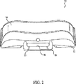
図7−図10は、それぞれ、図1の口腔装置1のための下側トレイ40の、正面図、底面図、上面図、および、側面図である。下側トレイ40は、一般的に、U字型をしている(たとえば、頂点46aから延在している2本の脚46b、46cを備える)。下側トレイ40は、下側支持部材41および下側成形可能素材54を含む。
7-10 are a front view, a bottom view, a top view, and a side view, respectively, of the
図11には、一実施例として、下側成形可能素材54に連結される、下側成形可能素材54が存在していない下側支持部材41の平面図が示されている。下側支持部材41は、接着表面43および咬合表面44を備えるベース42と、前面46および後面47を備える外壁45と、前面49および後面50を備える内壁48とを有する。細長い係合部材52(図10)は、咬合表面44から延在している。ランプ58は、内壁48の一部の上部から接着表面43上の多数のリブ60まで、下方向に勾配している。以下に詳述するように、ランプ58は、装着中に、トレイ40に対して、ユーザの歯列を中央に位置決めする際に役立つように構築される。これに対して、リブ60は、患者の上顎歯列と下顎歯列との間に、所望の垂直間隔の提供する際に役立つように構築される。下側支持部材41は、識別マーキング62を含んでもよい。現在の実施例では、限定的でない例示をすると、下側支持部材41は、咬合表面14(図8)上に、文字「L」および符号「000」を含む。
FIG. 11 shows a plan view of the
接着表面43は、ベース42に沿って脚46bから脚46cまで移動しても、一般的には、単一な平面となる(すなわち、接着表面43は、一般的に平面である)。しかしながら、代替実施形態では、接着表面43は、ユーザの歯列に関するスピーカーブをうまく収容するために、多少カーブしていることが意図される。具体的には、接着表面43は、ユーザの下顎歯列に関する凹状のスピーカーブを収容できるように、多少凸状であることが意図される。
As the
現在の実施例では、下側支持部材41の脚46b、46cは、所望の垂直間隔(たとえば、10ミリメートルの垂直間隔)の提供に役立つように構築されている多数の噛合パッド59も含んでいる。噛合パッド59は、ユーザの噛合圧力が装着プロセスの間にベース42の咬合表面44全体にわたって分配されるように、装着中に正確な噛合角度を促進するようなサイズとするとよい。しかしながら、現在の実施例では、各噛合パッド59は、同様のサイズとしているが、本発明の範囲内であれば、いろいろなサイズの噛合パッドとすることができる。
In the current embodiment, the legs 46b, 46c of the
一般的に、下側支持部材41は、ほぼ0.30インチ(7.62ミリメートル)からほぼ0.53インチ(13.46ミリメートル)までの第一幅(A')の頂点46aを有する。下側支持部材41は、第一脚46bと第二脚46cとの少なくとも一方に対して、ほぼ0.50インチ(12.70ミリメートル)からほぼ0.73インチ(18.54ミリメートル)までの第二幅(B')を有する。第一脚46bの外側部分と第二脚46cの外側部分との間の距離は、ほぼ2.0インチ(50.8ミリメートル)からほぼ2.80インチ(71.12ミリメートル)までの第三幅(C)となる。現在の実施例では、第一幅(A')は、ほぼ0.41インチ(10.41ミリメートル)であり、第二幅(B')は、ほぼ0.60インチ(15.24ミリメートル)であり、かつ、第三幅(C)は、ほぼ2.27インチ(57.66ミリメートル)である。
Generally, the
現在の実施例では、下側支持部材41は、第一幅(A')と第二幅(B')との間の比率が、ほぼ0.60からほぼ0.73までの間にあり、かつ、第一幅(A')と第三幅(C)との間の比率が、ほぼ0.17から0.19までの間となるようなサイズとされる。現在の実施例では、たとえば、第一幅(A')と第二幅(B')との間の比率は、ほぼ0.68であり、かつ、第一幅(A')と第三幅(C)との間の比率は、ほぼ0.18である。
In the present embodiment, the
図10を簡単に参照すれば、下側支持部材41は、頂点46aに対して、ほぼ、0.30インチ(7.62ミリメートル)から0.5インチ(12.70ミリメートル)までの第一高さ(D')を有し、かつ、第一脚46bと第二脚46cとの少なくとも一方に対して、ほぼ0.025インチ(0.635ミリメートル)からほぼ0.42インチ(10.67ミリメートル)までの第二高さ(E')を有する。現在の実施例では、第一高さ(D')および第二高さ(E')は、第一高さ(D')と第二高さ(E')との間の比率がほぼ0.083からほぼ0.125までの間となるように選択される。さらにまた、下側支持部材41は、ほぼ、0.30インチ(7.62ミリメートル)から0.48インチ(12.19ミリメートル)までの最大高さ(F')を有する。
Referring briefly to FIG. 10, the
現在の実施例では、第一高さ(D')は、ほぼ0.32インチ(8.13ミリメートル)であり、第二高さ(E')は、ほぼ0.032インチ(0.813ミリメートル)であり、第二高さ(E')と第一高さ(D')との間の比率は、ほぼ0.1であり、かつ、最大高さ(F')は、ほぼ0.42インチ(10.67ミリメートル)である。 In the current example, the first height (D ′) is approximately 0.32 inches (8.13 millimeters), the second height (E ′) is approximately 0.032 inches (0.813 millimeters), and the second height The ratio between (E ′) and the first height (D ′) is approximately 0.1, and the maximum height (F ′) is approximately 0.42 inches (10.67 millimeters).
下側支持部材41は、いかなる適切な強固または半強固な素材からなるものであってもよい。現在の実施例では、下側支持部材41が、ほぼ、0.040ポンド/インチ3から0.050ポンド/インチ3までの密度を有し、ほぼ、0.12インチ3から0.22インチ3までの容積を有し、かつ、ほぼ、0.0071ポンドから0.0081ポンドまでの重量を有する。たとえば、下側支持部材41は、ほぼ0.045ポンド/インチ3の密度、ほぼ0.18インチ3の容積、および、ほぼ0.0081ポンドの重量を有する、レキセインなどのポリカーボネート樹脂熱可塑性物質からなる。
The
上記のように、上側トレイ10は、内壁18の一部の上部からベース12の接着表面13上に置かれた棚部31まで、下方向の勾配を有するランプ30(図6に示す)を含み、かつ、下側トレイ40は、内壁48の一部の上部からベース42の接着表面43に置かれた多数のリブ60まで下方の勾配を有するランプ58(図11を示す)を含む。ランプ30は、上側トレイ10に対して、ユーザの上顎歯列の中央への位置決めを補助するように構築され、かつ、ランプ58は、装着中に下側トレイ40に対して、ユーザの下顎歯列の中央への位置決めを補助するように構築される。棚部31およびリブ60は、ユーザの上顎歯列と下顎歯列との間に、所望の垂直間隔の提供に役立つように構築される。
As described above, the
図11に戻ると、下側支持部材41は、下側領域51を規定する。下側領域51は、一般的には、限定的でない例示をすると、ベース接着表面43、外壁後面47、および、内壁前面49によって規定される。下側領域51は、その中で下側成形可能素材54の一部を担持することに適合している。下側成形可能素材54は、いかなる適切な手法によっても下側支持部材41に連結してもよく、限定的でない例示をすると、粘着剤を用いて連結することができる。
Returning to FIG. 11, the
下側成形可能素材54は、下側領域51に連結される場合に限定されるものではない。たとえば、図7、図8、および、図10に示すように、成形可能素材54の少なくとも一部は、下側領域51から延在している。現在の実施例では、下側成形可能素材54の一部は、外壁後面47より上に0.00984インチ(0.25ミリメートル)延在し、内壁前面49より上に少なくとも0.0256インチ(0.65ミリメートル)延在し、かつ、ベース42の接着表面43の端部から(すなわち、下側支持部材41の脚46b、46cの端部から)少なくとも0.00394インチ(0.1ミリメートル)延在していることが意図される。本発明の範囲内であれば、成形可能素材54が、下側領域51のいかなる部分からの延在量を変更することができる点に留意されたい。
The lower
上側成形可能素材24とともに既に説明したように、下側成形可能素材54は、加熱時に曲がることによって、装着中にユーザの歯列に合致し、かつ、冷却時に再硬化することによって、装着中に与えられたユーザの歯列の形状を保持するもの(すなわち、「ボイルアンドバイト」素材)を選択することができる。現在の実施例では、たとえば、下側成形可能素材54は、ほぼ0.035ポンド/インチ3の密度、ほぼ0.66インチ3の容積、および、ほぼ0.0231ポンドの重量を有する、エルバックスのようなエチレン酢酸ビニル共重合体樹脂である。
As already described with the upper
下側トレイ40が組み込まれている口腔装置1は、上側トレイ10とともに既に説明したように、単に成形可能素材のみを備える下側トレイを有する他の口腔装置、または、支持部材内に実質的に完全に含まれる成形可能素材から成る下側トレイを有する他の口腔装置を超える同じ利点を提供する。したがって、これらおよび他の理由により、下側支持部材41は、患者の快適さを増加させ、かつ、下側トレイ40をより広範囲の歯列弓サイズに装着させることが可能になる。
The
次に図9を参照すると、下側成形可能素材54は、その中にユーザの歯列を中央へ位置決めするように構築された溝55を有する。より詳しくは、溝55は、ユーザの下顎歯列(たとえば、下顎中歯、側歯、および、犬歯)の前方部分に係合するように構築されている実質的にV字型の部分56、および、ユーザの下顎歯列(たとえば、下顎小臼歯、および、臼歯)の後方部分に係合するように構築されている実質的にU字型の部分57を含む。ユーザの下位歯列を下側成形可能素材54内の中央に位置決めすることによって、ユーザまたはデンタル専門家は、上側トレイ10が選択された下側トレイ40に係合するときに、所望量の下顎誘導をうまく達成することができる。ユーザの歯を溝55内に中央に位置決めすることに加えて、V字型の部分56およびU字型の部分57は、ユーザの歯列と下側成形可能素材54との間の接触の増加を促進させる。したがって、改良されたユーザの歯列の印象が、装着プロセスの結果として、取得される。
Referring now to FIG. 9, the lower
上側成形可能素材24および下側成形可能素材54のいままでの考察は、エルバックスを用いることを対象としていたが、他の素材および/また各素材を組合せたものを用いてもよいという点には留意すべきである。たとえば、上側成形可能素材24および/または下側成形可能素材54は、ポリカプロラクトン・ポリマーまたは他の脂肪族ポリエステル(限定的でない例示をすると、ユニオン・カーバイド社によって製造された、TONE P-700、TONE P-767またはTONE P-787ポリカプロラクトン・ポリマー)から成ることが意図される。参照によって本願明細書に組み込まれたものとする、米国特許番号第6,247,926号および第5,807,100号は、この種の素材の例示を提供する。
The previous discussion of the upper
別の例として、上側成形可能素材24および/または下側成形可能素材54は、エルバックスとポリカプロラクトン・ポリマーまたは他の脂肪族ポリエステルとの組合せ、エルバックスと加熱時に曲がるポリカプロラクトンとの双方から成ることが意図される。したがって、これらの素材を、装着プロセスの間に、ユーザの歯列の周辺に良く流動させることが可能であり、これにより、カスタムな装着を提供することができる。冷却後、エルバックスは、相対的に可撓性が残り、かつ、患者の口内での口腔装置1の滞留が促進される。しかしながら、ポリカプロラクトンは、冷却後に相対的に強固になる。したがって、ポリカプロラクトンは、エルバックスに対する付加的な支持、エルバックスが単独で用いられるときに欠如する支持を提供する。参照によって本願明細書に組み込まれたものとする、米国特許番号第5,051,476号は、エルバックスおよびポリカプロラクトンのこの種の使用例を提供する。
As another example, the upper
本発明の範囲内であれば、エルバックスおよびポリカプロラクトンの特定の配置を変更することができる。図20−図21は、たとえば、成形可能素材24'、24"がエルバックス86およびポリカプロラクトン85の組合せを含む実施例による、上側トレイ10'、10"の断面図を示す。図20を参照すると、エルバックス86およびポリカプロラクトン85は、交互層に配置される。具体的には、成形可能素材24'は、2層のエルバックス86に挟まれたポリカプロラクトン85の層を含む。図20に示すように、成形可能素材24'は、この例でいえば、ポリカーボネートから構成されている支持部材11'によって担持される。本発明は、1層以上を除去すること、限定的でない例示をすると、支持部材11'に隣接するエルバックス層を除去することも考慮している。図21を参照すると、ポリカプロラクトン85は、エルバックス86内およびその全体にわたって懸濁される。成形可能素材24"は、この例でいえば、ポリカーボネートによっても構成される、支持部材11"によって担持される。
Within the scope of the present invention, the specific arrangement of Elbax and polycaprolactone can be altered. FIGS. 20-21 show cross-sectional views of the
図12は、上側トレイ10と下側トレイ40との係合を例示する。通常、下側トレイ40は、上側トレイ10に対して、ほぼ垂直に配置される。細長い係合部材52の最先端の52aは、端部52bが穴あき係合部材22の底部穴33に挿入されるように、穴あき係合部材22の一部に接触させる。それから、端部52bが正面穴32(図1を示す)に入力され、下側トレイ40および上側トレイ10は、指示矢34によって示されるように、互いに対して、ホックされるように、回転される。図1に示すように、係合時には、端部52bは、穴あき係合部材22内で、所定量の水平移動ができ(指示矢35によって示されるように)、かつ、所定量の垂直移動ができる(指示矢36によって示されるように)。現在の実施例では、たとえば、端部52bは、水平に10−13ミリメートル、および、垂直に0.8−1.2ミリメートル移動することができる。しかしながら、本発明の範囲内であれば、所定の水平方向および縦方向の移動量は、代替できる点に留意されたい。
FIG. 12 illustrates the engagement between the
下側トレイ40との上側トレイ10の係合が、穴あき係合部材22および係合部材52(すなわち、フックおよび穴配置)とともに記載されているが、本発明の範囲内であれば、代替の係合機構を用いることができる。さらにまた、本発明の範囲内であれば、係合部材の特定の配置は、代替することができる。たとえば、穴あき係合部材22は、下側トレイ40の下側支持部材41から延在させ、かつ、細長い支持部材52は、上側支持部材11から延在させてもよい。更なる例として、これに限定されるものではないが、本発明の範囲内であれば、細長い係合部材52の長さ、フック端部52bのサイズ、および、フック端部52bの位置決めは、代替することができる。
While the engagement of the
現在の実施例では、穴あき係合部材22は、ほぼ36ポンドの力が加えられたときに壊れるように構築されている、もろい部分23(図2を示す)を含む。しかしながら、もろい部分23は、いろいろな所望量の力がそこに加えられたときに壊れるように構築することができる。さらに、もろい部分23が壊れるように加えられる力は、その力が加えられる方向に応じて変更させることもできる。加えて、あるいは、これに代えて、細長い係合部材52は、もろい部分(図示せず)を含むことができる。
In the current embodiment, the
上記のように、多数の下側トレイ40の各々は、上側トレイ10に係合されるときに、いろいろな固定量の下顎誘導が与えられるように構築される。現在の実施例では、各下側トレイ40によって与えられる下顎誘導量は、たとえば、頂点46aにおける、外壁前面46の頂点46aに対する、細長い係合部材52の固定位置によって決定される。
As described above, each of the multiple
図7−図10に示されている下側トレイ40に対して、たとえば、細長い係合部材52の最先端の52aは、外壁前面46の頂点46aで、外壁前面からほぼ1.70ミリメートルが相殺される。この位置で、下側トレイ40は、ユーザの下位中央歯を、現在の実施例におけるユーザの上部中央歯に並べる、固定量の下顎誘導を提供するように構築される。
7-10, for example, the
他の例として、図13に示す下側トレイ40'は、ユーザの下位中央歯がユーザの上部中央歯からほぼ0.098インチ(2.5ミリメートル)外へ延在するように、固定量の下顎誘導を提供するように構築される(すなわち、下側トレイ40'がクラスIIIの不正咬合、すなわち、「反対咬合」を与える)。具体的には、細長い係合部材52'の最先端の52a'は、頂点46a'で外壁前面46'に対して、ほぼ4.20ミリメートルが相殺される。現在の考察では下側トレイ40および下側トレイ40'に制限されたが、いろいろな固定量の下顎誘導が与えられる他の下側トレイを提供することができることが意図される。たとえば、口腔装置1が、さらに、ユーザの下位中央歯がユーザの上部中央歯からほぼ0.197インチ(5ミリメートル)外へ延在するように、固定的な下顎誘導を提供する付加的な下側トレイを含むことが意図される。
As another example, the
下顎誘導量は、上側トレイ10と下側トレイ40とが非対称であるので、上側トレイ10および下側トレイ40を反転させることによって変更することもできる。たとえば、上側トレイ10がユーザの上顎歯列に装着され、かつ、下側トレイ40がユーザの下顎歯列に装着される場合には、口腔装置1は、ユーザの上部中央歯を、ユーザの下位中央歯に位置合わせさせるような下顎誘導量を与える。しかしながら、上側トレイ10がユーザの下顎歯列に装着され、かつ、下側トレイ40がユーザの上顎歯列に装着される場合には、口腔装置1は、ユーザの下位中央歯を、ユーザの中央上部歯からほぼ0.197インチ(5ミリメートル)外へ延在させるような(すなわち、クラスIIIの不正咬合、すなわち、「反対咬合」を生じさせるような)、下顎誘導量を与える。したがって、少数の下側トレイは、広範囲な下顎誘導を取得することが必要となるであろう。
Since the
口腔装置1は、上側トレイおよび下側トレイに連結するように構築された多数の保持トレイを含む、組立体/システムの一部とすることができる。たとえば、図14および図15は、下側トレイ40に係合される保持トレイ70を例示する。図16は、一実施例による保持トレイ70の底面図である。保持トレイ70は、そこに下側トレイ40を受け入れるようなサイズとされた一般的にU字型のフレーム71を含む。フレーム71は、そこから延在している外壁79を備えるベース78を含む。
The
現在の実施例では、ベース78は、細長い係合部材52を収容するように構築されるゲート77を含む。突き出しピン76は、保持トレイ70に接触する下側トレイ40を保持するように使用される。現在の実施例では、突き出しピン76は、ゲート77の後方側部に沿って置かれる。したがって、下側トレイ40と保持トレイ70とが連結されるときに、突き出しピン76は、下位トレイ40が保持トレイ70に「きちんとはまる」ように内壁48に係合される。
In the current embodiment, the base 78 includes a gate 77 that is constructed to accommodate the
現在の実施例では、保持トレイ70は、フレーム71の頂点73で、外壁79の前面80から突出する取手72も含む。取手70は、装着プロセスの間に、加熱媒体内で下側トレイ40を懸架するために、ユーザによって使用される。「ボイルアンドバイト」成型可能素材の場合には、たとえば、ユーザは、成形可能素材54が熱湯内に浸水されている間は、取手72を握り、かつ、保持することができる。一度、成形可能素材54が曲がると(たとえば、再構築されまたは鋳造されるために十分柔らかくなると)、ユーザは、熱湯から下側トレイ40を取り出し、かつ、下側トレイ40をユーザの口に挿入することができる。保持トレイ70は、装着プロセスの間に、ユーザの口への下側トレイ40の正確な挿入を促進する。具体的にいえば、ユーザが使用する保持トレイ70は、ユーザの口内に下側トレイ40をうまく位置合わせるために、取手72による付加的な働きが提供される。
In the current embodiment, the holding
ベース78の咬合表面81は、その上に置かれる多数の噛合パッド75を含むことができる。噛合パッド75は、他の素材も考察されるが、装着プロセスの間に、ユーザの快適さを増加させるエラストマー素材から構成することができる。加えて、装着プロセスの間に、ユーザの噛合圧力がベース78の咬合表面81全体にわたって分配されるように、噛合パッド75は、装着間に、正確な噛合角度を促進するようなサイズとすることができる。しかしながら、現在の実施例では、各噛合パッド75は、同様のサイズとしているが、本発明の範囲内であれば、噛合パッド75は、いろいろなサイズとすることができる。
The occlusal surface 81 of the base 78 can include a number of
本発明の範囲内であれば、保持トレイ70を変更することができることも、明らかである。限定的でない例示をすると、保持トレイ70は、ゲート77の前方側部に沿って置かれている突き出しピン76、および、下側トレイ40が保持トレイ70に「かちんとはまる」ように外壁45が係合される内壁を備えることができる。図14−図16に関する考察は、一般的には、下側トレイ40とともに保持トレイ70を用いることに制限されるが、保持トレイ70は、他の下側トレイおよび/または上側トレイ10を用いて構築してもよいことは明らかであろう。
Obviously, the holding
図17は、一実施例によるユーザの気道に開通性をもたらす操作プロセス90を例示する。操作プロセスは、上側トレイおよび複数の下側トレイを有する、図1に示された口腔装置1のような、口腔装置1を含む口腔装置組立体を提供する操作91から始まる。現在の実施例では、上側トレイ10は、ユーザの上顎歯列に合致するように適合化され、かつ、複数の下側トレイ40、40'の各々は、ユーザの下顎歯列に合致するように適合化される。上側トレイ10および下側トレイ40、40'は、ユーザの上顎歯列および下顎歯列に、それぞれ、たとえば、下記に詳述されるであろう操作プロセス100および操作プロセス110を用いて装着することができる。下側トレイ40、40'の少なくともいくつかの各々は、いろいろな固定量の下顎誘導を与えるために、上側トレイ10と連結するように構築される。
FIG. 17 illustrates an
操作制御は、操作91で口腔装置組立体が提供された後に、操作92に移される。操作92では、複数の下側トレイのうちの少なくとも1つが、選択される。現在の実施例では、下側トレイは、要求される下顎誘導の特定量に基づいて選択される。限定的でない例示をすると、下側トレイ40は、ユーザの下位中央歯を、ユーザの上部中央歯に並べるような固定量の下顎誘導を提供するように構築される。これに対して、下側トレイ40'は、ユーザの下位中央歯がユーザの上部中央歯からほぼ2.5ミリメートル外へ延在するように、固定量の下顎誘導を提供するように構築される(すなわち、トレイ40'がクラスIIIの不正咬合、すなわち、「反対咬合」を与える)。正確な下側トレイの選択は、デンタル専門家、ユーザまたは他者によってなされてもよい。
Operation control is transferred to
操作制御は、下側トレイのうちの1つが選択された後に、操作93に移される。操作93では、上側トレイは、下顎誘導が所望量となる口腔装置を形成するために、選択された下側トレイに連結される。現在の実施例では、上側トレイ10は、穴あき係合部材22を含み、かつ、下側トレイ40、40'は、細長い係合部材52を含む。図12とともに既述したように、上側トレイ10および選択された下側トレイ40、40'は、連結することができる。上側トレイと下側トレイとが連結された後に、口腔装置は、ユーザの気道に開通性の効果が得られるように、ユーザの口に挿入される。
Operation control is transferred to
図18は、一実施例による口腔装置を装着させるための操作プロセス100を例示する。操作プロセス100は、操作101で、ユーザの歯列の刻印を取り出すことによって始まる。刻印は、一般的には、ユーザの歯列には、あまり類似していない。通常、刻印は、ユーザの歯列と接触している間に、硬質またはセットされるプラスチック材料を用いて、デンタル専門家によって取り出される。現在の実施例では、2つの刻印が取り出される。一つはユーザの上顎歯列の刻印である。もう一つはユーザの下顎歯列の刻印である。
FIG. 18 illustrates an
操作制御は、刻印の完了後に、ユーザの歯列の鋳造物が作成される、操作102に移される。鋳造物は、たとえば、焼石膏または人工石を刻印に充填することによって作成することができる。現在の実施例では、ユーザの上顎歯列と下顎歯列との双方の鋳造物が作成される。鋳造物は、一旦作成が完了すれば、ユーザの上顎歯列および下顎歯列の複製を提供することになる。
Operation control is transferred to
その後、鋳造物は、操作103で、所定の温度まで加熱される。現在の実施例では、操作102で作成される各鋳造物は、加熱媒体、限定的でない例示をすると、水中に置かれる。加熱媒体の温度は、ほぼ、華氏180度から220度までの間(ほぼ、摂氏82.22度から104.4度までの間)に保持される。加えて、現在の実施例では、上側トレイ10および選択された下側トレイ40は、さらに、成形可能素材24および成形可能素材54が曲がり始める(すなわち、軟化する)ように、加熱媒体に置かれる。加熱手法および所定の温度の値は、本発明の範囲内であれば、代替できる点に留意されたい。
Thereafter, the casting is heated to a predetermined temperature in
鋳造物は、所定の温度に到達した後に、口腔装置の成形可能素材に押圧される。現在の実施例では、ユーザの上顎歯列についての加熱された鋳造物は、上側トレイ10の上側成形可能素材24内に置かれる。この鋳造物によって保持される熱によって、上側成形可能素材24が、より長い間、曲げられた状態のまま維持され、これにより、ユーザの上顎歯列の非常に正確な印象が、上側成形可能素材24内に形成されることになる。上側成形可能素材24は、一旦冷却されてから、ユーザの上顎歯列に装着される。同様に、ユーザの下顎歯列についての加熱された鋳造物は、下側トレイ40の下側成形可能素材54内に置かれる。この鋳造物によって保持される熱によって、下側成形可能素材54が、より長い間、曲げられた状態のまま維持され、これにより、ユーザの下顎歯列の非常に正確な印象が、下側成形可能素材54内に形成されることになる。一旦冷却されてから、下側成形可能素材54は、ユーザの下顎歯列に装着される。
The cast is pressed against the moldable material of the oral device after reaching a predetermined temperature. In the current embodiment, the heated casting for the user's upper dentition is placed in the upper
図19は、他の実施例による口腔装置を装着するための操作プロセス110を例示する。操作プロセス110が始まり、口腔装置トレイが、操作111で、保持トレイに連結される。現在の実施例では、口腔装置トレイは、成形可能素材24を備える上側トレイ10と、成形可能素材54、54'を備える下側トレイ40、40'との少なくとも一方であり、かつ、保持トレイ70は、そこに取り付けられる取手72を有する。
FIG. 19 illustrates an
操作制御は、口腔装置トレイと保持トレイとが連結された後に、口腔装置トレイが加熱媒体内に浸水され、取手の少なくとも一部が、加熱媒体外に残されるという、操作112に移される。上側トレイ10に関して、たとえば、ユーザは、取手72の端部を握ることができ、かつ、上側トレイ10を熱湯内に浸水させられる。ユーザは、上側トレイ10を浸水させるが、取手72(熱湯に沈んでいない)を持ち続けることができる。
Operation control is transferred to
その後、操作制御は、口腔装置トレイが、取手を用いて加熱媒体から取り出されるという、操作113に移される。上記の例で進めると、ユーザは、上側成形可能素材24が曲げられた状態に到達した後に、上側トレイ10を熱湯から(取手72によって)取り出せばよい。
Thereafter, operation control is transferred to
その後、操作制御は、口腔装置トレイが、取手を用いてユーザの口に挿入されるという、操作114に移される。同じ例で進めると、ユーザは、取手72を保持して、上側トレイ10をそれらの口に挿入すればよい。取手72は、ユーザの口内に上側トレイ72の正確な整列が容易になるように、ユーザに付加的な力を提供する。加えて、取手72は、ユーザが、熱湯内に浸水され、まだ多少熱いであろう上側トレイ10に触れる必要性を排除する。
Thereafter, operation control is transferred to
操作制御は、口腔装置トレイがユーザの口に挿入された後に、ユーザの歯列の少なくとも一部の印象が作成されるという、操作115に移される。現在の例では、ユーザは、曲げられた状態の上側成形可能素材24を咬むことが可能となる。その後、上側成形可能素材24は、印象を形成するように、ユーザの歯列の周辺に流動する。
Operation control is transferred to
口腔装置1の装着のために操作プロセス100と操作プロセス110との双方が用いられるが、操作プロセス100は、操作プロセス110よりも正確な結果を提供することができる。一般的には、鋳造物は、成形可能素材よりも多くの熱を保持する。この熱は、鋳造物から成形可能素材まで伝わる。これにより、成形可能素材は、成形可能素材を単独で加熱する場合に比較して、長時間、曲げられた状態が維持される(たとえば、操作プロセス110)。成形可能素材を長時間曲げられた状態とすることができるので、成形可能素材を鋳造物の周辺に流動させる良い機会が得られ、印象が形成される。さらに、成形可能素材が一度置かれると、鋳造物は、実質的に静止したままとなり、ユーザが、直接、成形可能素材(操作プロセス110)を、彼(又は彼女)の顎に移動させられるであろう。
Although both the
口腔装置1は、さらに、患者インターフェイス・デバイスによる使用に適合するであろう。睡眠時無呼吸のための処置を受けている患者は、たとえば、鼻マスク、オーラルマスク、フルフェースマスクまたは他の患者インターフェイス・デバイスを着用することが要求される。患者インターフェイス・デバイスと組み合わせて使用する口腔装置の例は、米国特許第2,521,084号、第4,470,413号、第5,573,994号、第5,752,510号、第5,954,048号、第6,012,455号、第6,405,729号、第6,789,543号、および、第7,021,312号に記載されている。これらの特許の各々の内容は、本願明細書に引用したものとする。
The
図22は、睡眠時無呼吸および/または他の呼吸病気を治療するためのシステム90を例示する。現在の実施例では、システム90は、圧力生成デバイス91、鼻マスク92、導管93、および、口腔装置1'を含む。線図的に、口腔装置1'が、導管93を通じて圧力生成デバイス91に有効に接続された鼻マスク92に連結されている点が示されている。口腔装置1'は、患者の顔に対して、鼻マスク92を固定させるように構築されている。鼻マスク92は、患者の気道に、ガス生成デバイス91によって製造される加圧呼吸ガスの流動を供給するように構築される。鼻機器92は、口腔装置1'との結合によって、患者の顔に固定され、患者の睡眠時無呼吸および/または他の呼吸支持器は、下顎誘導と正しい気道圧力の用途との双方によって取り扱われる。口腔装置1'は、いかなる適切な手法で、患者のインターフェイス・デバイスに連結してもよいことが意図される。
FIG. 22 illustrates a
口腔装置1は、患者の監視デバイスおよび/または口腔内電気筋肉刺激デバイスと組み合わせて用いても良い。患者の監視デバイスおよび/または口腔内電気筋肉刺激デバイス用に、口腔装置から延在している電極を備える口腔装置の例は、米国特許番号第6,618,627号、および、第5,190,053号に記載されている。これらの特許の各々の内容は、本願明細書に引用したものとする。図23は、一実施例による口腔装置1"から延在する電極95、95'を備える口腔装置1"を例示する。
The
電極95、95'は、たとえば、患者の1以上の筋肉(たとえば、咬筋)によって得られる筋電図(EMG)活動をキャプチャーするように、構築されている。限定的でない例示をすると、測定された筋電図活動は、歯ぎしりおよび口腔装置の装着の遵守を監視するために使用される。筋電図電極95、95'は、口腔装置1"の装着後に、対象となる筋肉の筋電図活動がキャプチャーされるように、口腔装置1"のいかなる適切な位置に置かれてもよい。図23に示すように、たとえば、筋電図電極95は、上側成形可能素材24"に置かれ、かつ、筋電図電極95'は、下側支持部材41"に置かれる。監視システム(図示せず)は、無線で、筋電図電極95、95'と通信する。監視システムは、咬筋で検出される筋電図活動を分析するためのプロセッサを含む。
The
電極95、95'は、他の実施例のように、閉塞性睡眠時無呼吸などの呼吸障害の発生を減少または最小とすべく、口腔内電気筋肉の刺激を提供するように構築される。たとえば、口腔内電気筋肉の刺激は、気道の開通性を保持する原因となる上気道の筋肉に電気刺激を提供するために使用される。一般的に、電気筋肉の刺激は、上気道の筋肉の収縮を誘発し、これによって、ユーザの気道の遮断を防止または最小となる。
The
電極95、95'の数、タイプ、機能、および、位置、本発明の範囲内であれば、代替できる点は明らかである。たとえば、上側トレイ10"のみが、その上に置かれる電極95を有することができ、および/または、電極95、95'は、監視システムと通信するための有線を含むことができる。電極95、95'は、上側成形可能素材24、下側成形可能素材54、またはこれら双方の表面に、直接、置いてもよい。成形プロセスの間に、上側成形可能素材24または下側成形可能素材54は、通常、外側へ、すなわち、歯が成形可能素材に係合するように、ユーザの口腔内表面の方へ移動される。上側成形可能素材24および/または下側成形可能素材54の当該外側への移動は、他の電極配置デバイスが必要とされないように、ユーザの口腔内表面を備える電極に接触するように機能する。それでもやはり、本発明は、電極95、95'を確実にユーザの口腔内表面に係合させるための、スプリングおよび支持部材のような電極配置デバイスを使用することも考慮している。さらにまた、他の患者の監視デバイス(たとえば、振動監視デバイス、音声監視デバイスなど)および/または部品が、口腔装置1とともに用いることができるとも考えられる。
Obviously, the number, type, function, and position of the
本発明は、最も有用かつ好ましい実施例であるとの現在の考察に基いて説明することを目的として詳述されたが、この種の詳述は単にこの目的のためであって、本発明が、開示された実施例に限定されるものでなく、そればかりか、添付の特許請求の範囲内であれば変更態様および等価な構成をカバーすることが意図されると理解されたい。たとえば、本発明が、可能な程度で、いかなる実施例の一つ以上の特性が他のいかなる実施例の一つ以上の特性と組み合わせることができることを理解されたい。 Although the present invention has been described in detail for purposes of illustration based on current considerations as being the most useful and preferred embodiment, this type of detail is solely for this purpose and the present invention is not limited thereto. It should be understood that the invention is not limited to the disclosed embodiments, but is intended to cover modifications and equivalent constructions as long as they are within the scope of the appended claims. For example, it should be understood that the present invention, to the extent possible, can combine one or more characteristics of any embodiment with one or more characteristics of any other embodiment.
Claims (10)
各々がユーザの下顎歯列に適合する複数の下側トレイであって、各下側トレイは、前記上側トレイに係合することにより、それぞれ異なる固定量の下顎誘導を与えることが可能であるように構築され、前記複数の下側トレイの1つが、所望の量の下顎誘導を得るためにユーザにより選択される、複数の下側トレイと、
を備え、前記上側成形可能素材は、ユーザの上顎歯列をその中央に位置決めするように構築された溝を有し、当該溝は、ユーザの上顎歯列の前方部分に係合するV字型の溝部分およびユーザの上顎歯列の後方部分に係合するU字型の溝部分を含む、口腔装置システム。An upper tray adapted to a user's maxillary dentition, an upper moldable material that contacts and engages the maxillary dentition, and an upper support member that defines an upper region carrying a portion of the upper moldable material; An upper tray having
A plurality of lower trays, each adapted to a user's lower dentition, each lower tray being capable of providing a different fixed amount of lower jaw guidance by engaging the upper tray. A plurality of lower trays, wherein one of the plurality of lower trays is selected by a user to obtain a desired amount of lower jaw guidance ;
The upper moldable material has a groove constructed to position the user's maxillary dentition in the middle thereof, the groove engaging a front portion of the user's maxillary dentition. And a U-shaped groove portion that engages a posterior portion of the user's maxillary dentition .
下顎歯列に係合する下側成形可能素材と、
前記下側成形可能素材の一部を担持する下部領域を規定する下側支持部材と、を備える請求項1又は2に記載の口腔装置システム。 Each lower tray,
And lower moldable material to engage the lower dental,
Oral appliance system according to claim 1 or 2 and a lower support member defining a lower region you carrying a portion of the lower moldable material.
前記穴あき係合部材及び前記細長い係合部材は、前記細長い係合部材の一部が、前記穴あき係合部材の前記穴内で、所定量の水平移動および所定量の垂直移動が可能であるように構成される、請求項5又は6に記載の口腔装置システム。 The upper tray and the lower tray are engaged by inserting a part of the elongated engagement member into the hole of the perforated engagement member,
The perforated engagement member and the elongated engagement member are such that a part of the elongated engagement member is capable of a predetermined amount of horizontal movement and a predetermined amount of vertical movement within the hole of the holed engagement member. oral appliance system according constituted, in claim 5 or 6 as.
Applications Claiming Priority (3)
| Application Number | Priority Date | Filing Date | Title |
|---|---|---|---|
| US81340506P | 2006-06-14 | 2006-06-14 | |
| US60/813,405 | 2006-06-14 | ||
| PCT/US2007/068784 WO2007146523A2 (en) | 2006-06-14 | 2007-05-11 | Oral appliance for treatment of snoring and sleep apnea |
Related Child Applications (1)
| Application Number | Title | Priority Date | Filing Date |
|---|---|---|---|
| JP2012241848A Division JP2013017896A (en) | 2006-06-14 | 2012-11-01 | Oral appliance for treatment of snoring and sleep apnea |
Publications (3)
| Publication Number | Publication Date |
|---|---|
| JP2009539559A JP2009539559A (en) | 2009-11-19 |
| JP2009539559A5 JP2009539559A5 (en) | 2010-07-01 |
| JP5129246B2 true JP5129246B2 (en) | 2013-01-30 |
Family
ID=38832603
Family Applications (2)
| Application Number | Title | Priority Date | Filing Date |
|---|---|---|---|
| JP2009515549A Expired - Fee Related JP5129246B2 (en) | 2006-06-14 | 2007-05-11 | Oral devices for the treatment of snoring and sleep apnea |
| JP2012241848A Pending JP2013017896A (en) | 2006-06-14 | 2012-11-01 | Oral appliance for treatment of snoring and sleep apnea |
Family Applications After (1)
| Application Number | Title | Priority Date | Filing Date |
|---|---|---|---|
| JP2012241848A Pending JP2013017896A (en) | 2006-06-14 | 2012-11-01 | Oral appliance for treatment of snoring and sleep apnea |
Country Status (5)
| Country | Link |
|---|---|
| US (3) | US8205617B2 (en) |
| EP (1) | EP2032067B1 (en) |
| JP (2) | JP5129246B2 (en) |
| CN (1) | CN101553194B (en) |
| WO (1) | WO2007146523A2 (en) |
Families Citing this family (59)
| Publication number | Priority date | Publication date | Assignee | Title |
|---|---|---|---|---|
| US7748386B2 (en) | 2006-04-06 | 2010-07-06 | Thornton W Keith | Oral appliance for treating a breathing condition |
| US9241825B2 (en) * | 2007-11-13 | 2016-01-26 | Apnicure, Inc. | Oral device for mandibular advancement and medial tongue constraint |
| US9655768B2 (en) | 2007-11-13 | 2017-05-23 | Apnicure, Inc. | Oral device for mandibular advancement and medial tongue constraint |
| US10772756B2 (en) | 2007-11-13 | 2020-09-15 | Somnics, Inc. | Oral device for mandibular advancement and medial tongue constraint |
| US8783259B2 (en) * | 2008-05-02 | 2014-07-22 | Cadwell Therapeutics, Inc. | Oral appliance for improved nocturnal breathing |
| AU2009250326A1 (en) * | 2008-05-21 | 2009-11-26 | Stewart Cullen | Device for the alleviation of snoring and sleep apnoea |
| WO2010073148A1 (en) * | 2008-12-23 | 2010-07-01 | Koninklijke Philips Electronics, N.V. | Method and apparatus comprising stepped mouthpiece for aerosol drug delivery |
| US8312884B2 (en) * | 2008-12-24 | 2012-11-20 | Brian D Fuselier | Intra-oral apnea and snoring prevention appliance |
| EP2233115A1 (en) * | 2009-03-24 | 2010-09-29 | Michel Valceschini | Dental appliance for adjusting the position of the lower jaw |
| FR2951931B1 (en) * | 2009-10-30 | 2012-02-10 | Dornberger & Fils | DEVICE COMPRISING A GUTTER FOR DENTAL FOOTPRINTING AND PROTECTION AGAINST THE CONSEQUENCES OF BRUXISM |
| US20110174319A1 (en) * | 2010-01-15 | 2011-07-21 | Busciglio David J | Apparatus for the suppression of grinding and/or clenching of teeth |
| WO2011161556A1 (en) * | 2010-06-22 | 2011-12-29 | Koninklijke Philips Electronics N.V. | A mouthpiece for cleaning teeth with a mechanical drive train |
| US8833374B2 (en) * | 2010-12-13 | 2014-09-16 | James S. Fallon | Intra-oral mandibular advancement appliance |
| US8684007B2 (en) * | 2011-03-30 | 2014-04-01 | William R. Timmons | Oral appliance for the treatment of sleep apnea |
| WO2012138459A1 (en) | 2011-04-05 | 2012-10-11 | Airway Technologies, Llc | Oral appliance for treating particular disorders associated with sleep |
| EP2760389B1 (en) | 2011-09-30 | 2018-12-05 | Robert Rogers | Methods and oral orthotic systems for use in connection with sleep-disordered breathing |
| FR2980684B1 (en) * | 2011-10-04 | 2014-08-22 | Petelle Fleury Rech S Pfr | INTRABUCCAL ORTHESIS, METHOD OF MANUFACTURE, AND METHOD OF USING SUCH ORTHESIS. |
| FR2981843B1 (en) | 2011-10-28 | 2017-03-10 | Orthodontie Alliance Laboratoire | DEVICE FOR ACTIVATION OF MANDIBULAR GROWTH, MAXILLARY GROWTH AND MANDIBULAR PROPULSION |
| AU2012343270B2 (en) * | 2011-11-25 | 2017-01-05 | Braebon Medical Corporation | Method and apparatus for verifying compliance with dental appliance therapy |
| BR112015017600A8 (en) * | 2013-01-23 | 2019-11-05 | Hyun jin CHOI | mouthpiece |
| US20160074207A1 (en) * | 2013-01-23 | 2016-03-17 | Hyun-Jin Choi | Oral appliance |
| EP2967974B1 (en) * | 2013-03-14 | 2019-11-13 | ZST Holdings, Inc. | Systems for providing an automated titration for oral appliance therapy |
| US11833075B2 (en) | 2013-10-24 | 2023-12-05 | Dante Togliatti | Dental appliance |
| US9820882B2 (en) | 2013-12-30 | 2017-11-21 | Prosomnus Sleep Technologies | Mandibular advancement device |
| CA2939102A1 (en) | 2014-02-13 | 2015-08-20 | Silverfox Dental & Ortho, Llc | Oral motion preservation device |
| SE1450930A1 (en) * | 2014-08-11 | 2015-10-13 | Braincool Ab | Mouth cooler |
| US20160051398A1 (en) * | 2014-08-25 | 2016-02-25 | Airway Technologies, Llc | Oral appliance |
| US11426304B2 (en) | 2014-08-25 | 2022-08-30 | Airway Technologies, Llc | Oral appliance |
| US10376408B2 (en) | 2014-08-25 | 2019-08-13 | Airway Technologies, Llc | Oral appliance |
| US10327944B2 (en) * | 2014-11-05 | 2019-06-25 | James Palmer Boyd | Dental mouthpiece for treating snoring or apnea and method of assembly |
| US10537463B2 (en) | 2015-01-13 | 2020-01-21 | Align Technology, Inc. | Systems and methods for positioning a patient's mandible in response to sleep apnea status |
| US10588776B2 (en) | 2015-01-13 | 2020-03-17 | Align Technology, Inc. | Systems, methods, and devices for applying distributed forces for mandibular advancement |
| US10517701B2 (en) | 2015-01-13 | 2019-12-31 | Align Technology, Inc. | Mandibular advancement and retraction via bone anchoring devices |
| USD752760S1 (en) * | 2015-02-11 | 2016-03-29 | Respire Medical Holdings, LLC | Oral sleep appliance |
| US10010313B2 (en) | 2015-05-18 | 2018-07-03 | Richard L. Arden | Mandibular subluxation device and method |
| US10258319B2 (en) | 2015-05-18 | 2019-04-16 | Richard L. Arden | Airway assist device and method |
| US10342526B2 (en) | 2015-07-01 | 2019-07-09 | Richard L. Arden | Airway assist device and method |
| US20170014262A1 (en) * | 2015-07-14 | 2017-01-19 | Thermal Fit, LLC | Intraoral Orthosis Device and Method for Manufacturing |
| USD759824S1 (en) * | 2015-09-30 | 2016-06-21 | Kenneth Luco | Retainer for sleep apnea |
| KR101772768B1 (en) * | 2015-11-27 | 2017-08-29 | 한국 한의학 연구원 | Method and apparatus for correcting temporomandibular joint |
| BE1023871A9 (en) * | 2016-02-26 | 2017-08-31 | Antonio Cavaleri | Device for reducing noise nuisance related to snoring |
| EP3445272B1 (en) * | 2016-04-20 | 2021-07-14 | Advanced Facialdontics LLC | Apparatus and method for reducing bruxism and occlusal forces |
| US11517402B2 (en) * | 2016-04-20 | 2022-12-06 | Advanced Facialdontics Llc | Apparatus and method for reducing bruxism and occlusal forces |
| CN113576734A (en) * | 2016-06-28 | 2021-11-02 | 三井化学株式会社 | Tooth socket |
| CN105997331A (en) * | 2016-07-28 | 2016-10-12 | 刘帆 | Electrical stimulation snoring stopping braces |
| CN106473851A (en) * | 2016-07-28 | 2017-03-08 | 姜晓蕾 | A kind of Medical oral cavity corrects tooth-hardening apparatus |
| CN108472107B (en) * | 2016-10-20 | 2021-02-26 | 堤欧股份有限公司 | Dental retractor |
| JP2020500587A (en) * | 2016-11-30 | 2020-01-16 | オーベンタス・メディカル・リミテッドOventus Medical Limited | Monitoring of oral appliances |
| FR3059544B1 (en) * | 2016-12-07 | 2019-05-10 | Oniris | INTRABUCCAL DEVICE WITH PAIR OF ARTICULATED DENTAL GUTTERS |
| US10398894B2 (en) * | 2016-12-27 | 2019-09-03 | Colgate-Palmolive Company | Oral device with activating element |
| SE543188C2 (en) * | 2017-10-26 | 2020-10-20 | Dormitek Medical Ab | Mouthpiece for reduced snoring, teeth pressing and grinding |
| US10849783B2 (en) * | 2018-01-16 | 2020-12-01 | James S. Fallon | Full movement jaw advancement oral appliance to reduce the effects of snoring and/or sleep apnea |
| US11154459B2 (en) * | 2018-03-16 | 2021-10-26 | Regents Of The University Of Minnesota | Intraoral device and method for the use thereof |
| US20200121984A1 (en) * | 2018-10-17 | 2020-04-23 | Signifier Medical Technologies Limited | Oral muscle training |
| USD888249S1 (en) * | 2019-01-15 | 2020-06-23 | Ryan Bruss | Mouthguard |
| JPWO2021054133A1 (en) * | 2019-09-19 | 2021-03-25 | ||
| CN110547904A (en) * | 2019-10-05 | 2019-12-10 | 扬州市君瑞企业管理有限公司 | Simple snore preventing device for hospital physiotherapy and rehabilitation |
| USD976413S1 (en) | 2019-11-19 | 2023-01-24 | Advanced Facialdontics, Llc | Dental apparatus having unilateral bite block |
| USD932626S1 (en) | 2020-05-13 | 2021-10-05 | ProSomnus Sleep Technologies, Inc. | Mandibular advancement device with comfort bumps |
Family Cites Families (57)
| Publication number | Priority date | Publication date | Assignee | Title |
|---|---|---|---|---|
| US2521084A (en) | 1949-09-01 | 1950-09-05 | William T Oberto | Mandible cushion for oxygen masks |
| US3411501A (en) * | 1966-03-02 | 1968-11-19 | Greenberg Samuel | Thermoplastic mouthpiece and method of making same |
| US3878610A (en) | 1973-11-19 | 1975-04-22 | William Alfred Coscina | Low profile dental impression tray and set of such trays |
| JPS5358191A (en) * | 1976-11-05 | 1978-05-25 | Osamu Yoshii | Method of producing dental correction treating instrument using silicon resin material |
| US4255138A (en) | 1979-08-31 | 1981-03-10 | Frohn Hermann Josef | Apparatus for use in maxillary orthopaedics |
| US4350154A (en) | 1981-04-16 | 1982-09-21 | Feldbau Elliot V | Teeth protecting device |
| DE3202870C2 (en) | 1982-01-29 | 1985-03-21 | Drägerwerk AG, 2400 Lübeck | Breathing connection with mouthpiece for breathing apparatus |
| US4764111A (en) | 1985-11-21 | 1988-08-16 | Knierim Rupert W | Reminder and enforcer apparatus |
| DE3770239D1 (en) | 1986-10-15 | 1991-06-27 | Sunstar Inc | MOUTHPIECE AND METHOD FOR PRODUCING THIS. |
| US5092346A (en) | 1987-10-13 | 1992-03-03 | Hays & Meade, Inc. | Dental orthosis for alleviation of snoring |
| DE3923744C1 (en) | 1989-07-18 | 1990-08-23 | Frohn, Hermann-Josef, Dr., 5460 Linz, De | |
| US5042506A (en) * | 1989-11-02 | 1991-08-27 | Liberati Salvator P | Antisnoring training device |
| AU642266B2 (en) | 1990-06-25 | 1993-10-14 | Kevin John Bourke | Method and apparatus for dental treatment |
| US5190053A (en) | 1991-02-28 | 1993-03-02 | Jeffrey A. Meer, Revocable Living Trust | Method and apparatus for electrical sublingual stimulation |
| US5624257A (en) | 1991-10-31 | 1997-04-29 | Farrell; Christopher J. | Oral appliance |
| JP3103848B2 (en) * | 1991-12-09 | 2000-10-30 | サンメディカル株式会社 | Orthodontic appliance and method of manufacturing the same |
| US5868138A (en) | 1993-04-13 | 1999-02-09 | Silent Knight Ventures, Inc. | Dental appliance for treatment of snoring and obstructive sleep apnea |
| US6041784A (en) | 1993-04-13 | 2000-03-28 | Silent Knights Ventures Inc. | Dental appliance for treatment of snoring and obstructive sleep apnea |
| US6729335B1 (en) | 1993-04-13 | 2004-05-04 | Silent Knights Ventures Inc. | Dental appliance for treatment of snoring and obstructive sleep apnea |
| US5365945A (en) | 1993-04-13 | 1994-11-22 | Halstrom Leonard W | Adjustable dental applicance for treatment of snoring and obstructive sleep apnea |
| CA2165304C (en) | 1993-06-14 | 1999-08-31 | Kenneth L. Hilsen | Snoring and sleep apnea device |
| US5427117A (en) | 1993-09-29 | 1995-06-27 | Thornton; W. Keith | Apparatus for prevention of snoring and improved breathing during sleep |
| US5499633A (en) | 1993-12-17 | 1996-03-19 | Fenton; Douglas F. | Anti-snoring device with adjustable upper and lower relational members |
| US5465734A (en) * | 1994-01-12 | 1995-11-14 | Snorex, Inc. | Adjustable tongue positioning device and method |
| US5409017A (en) * | 1994-01-19 | 1995-04-25 | The University Of British Columbia | Mandible repositioning appliance |
| US5678567A (en) | 1994-03-25 | 1997-10-21 | Thornton; W. Keith | Apparatus for adjusting a dental device |
| US5573994A (en) | 1994-05-13 | 1996-11-12 | University Of Cincinnati | Superabsorbent foams, and method for producing the same |
| US5954048A (en) | 1994-06-03 | 1999-09-21 | Thornton; W. Keith | Device and method for improving breathing |
| US5537994A (en) | 1994-06-03 | 1996-07-23 | Thornton; W. Keith | Combination face mask and dental device for improved breathing during sleep |
| FR2737403B1 (en) | 1995-07-31 | 1997-09-26 | David Michel | INTRABUCCAL DEVICE, IN PARTICULAR FOR TREATING SNORING |
| US5642737A (en) | 1996-05-06 | 1997-07-01 | Parks; Scotty M. | Device for alleviating snoring |
| US5807100A (en) | 1996-05-24 | 1998-09-15 | Thornton; W. Keith | Dental device having an improved deformable material and method for forming same |
| US6012455A (en) | 1996-11-14 | 2000-01-11 | Goldstein; Joseph | Nasal air delivery apparatus |
| US5752510A (en) | 1996-11-14 | 1998-05-19 | Goldstein; Joseph | Nasal and oral air passageway delivery management apparatus |
| US5829441A (en) | 1997-06-24 | 1998-11-03 | Nellcor Puritan Bennett | Customizable dental device for snoring and sleep apnea treatment |
| AU5911399A (en) * | 1998-09-16 | 2000-04-03 | W. Keith Thornton | Device and method for improving breathing |
| US6129084A (en) | 1998-10-22 | 2000-10-10 | Bergersen; Earl O. | Intra-oral appliance for the prevention of snoring |
| US6212435B1 (en) * | 1998-11-13 | 2001-04-03 | Respironics, Inc. | Intraoral electromuscular stimulation device and method |
| US6170485B1 (en) * | 1999-11-10 | 2001-01-09 | Anthony J. Orrico | Anti-snoring device |
| US7802987B1 (en) * | 1999-12-17 | 2010-09-28 | Align Technology, Inc. | Methods and systems for lubricating dental appliances |
| GB2357433A (en) * | 1999-12-22 | 2001-06-27 | Estrange Peter L | Intra-oral device |
| US6247926B1 (en) | 2000-01-17 | 2001-06-19 | W. Keith Thornton | Oral appliance having a bonding layer and methods for fitting and relining same |
| US6877513B2 (en) * | 2000-01-21 | 2005-04-12 | Respironics, Inc. | Intraoral apparatus for enhancing airway patency |
| US6405729B1 (en) | 2000-04-05 | 2002-06-18 | W. Keith Thornton | Oral appliance for improving breathing and method of constructing same |
| US6435870B1 (en) | 2000-09-28 | 2002-08-20 | Kevin C. Walde | Orthodontic distalizing appliance |
| US6584978B1 (en) | 2001-05-25 | 2003-07-01 | Sportsguard Laboratories, Inc. | Mouthguard and method of making |
| US6447292B1 (en) * | 2001-05-29 | 2002-09-10 | Richard Champagne | Dental impression tray and bite registration rim assembly |
| ATE369105T1 (en) | 2002-05-01 | 2007-08-15 | Keith W Thornton | DEVICE FOR IMPROVING A PERSON'S BREATHING |
| US6789543B2 (en) | 2002-07-02 | 2004-09-14 | James L. Cannon | Assisted breathing device and method of wearing same |
| US7143767B2 (en) * | 2002-11-07 | 2006-12-05 | Christopher Zacco | Mouthpiece for reducing snoring |
| AU2004202518A1 (en) * | 2003-06-13 | 2005-01-06 | Christopher John Farrell | Oral appliance |
| BE1015642A3 (en) * | 2003-08-08 | 2005-07-05 | Nelissen Jozef Frans | Device for the treatment of nocturnal breathing problems. |
| NL1025223C2 (en) * | 2004-01-13 | 2005-07-14 | Bruxtec B V | Device against bruxism. |
| EP1602347A1 (en) | 2004-06-04 | 2005-12-07 | Georges Magnin | Mandibular advancer orthesis. |
| US7021312B2 (en) | 2004-07-08 | 2006-04-04 | Cannon James L | Assisted breathing device and method of wearing same |
| DE102004058081A1 (en) * | 2004-12-01 | 2006-06-08 | Toussaint, Winfried, Dr. | Two-part lower jaw protrusion splint for inhibiting snoring and/or obstructive sleep apnea has upper and lower shell parts e.g. of polyethylene and polyvinyl acetate copolymer with screw and guide rail for adjusting length |
| US20070283973A1 (en) | 2006-06-05 | 2007-12-13 | Longley William H | Apparatuses, Systems and Methods for Confirming Use of an Oral Appliance |
-
2007
- 2007-05-11 JP JP2009515549A patent/JP5129246B2/en not_active Expired - Fee Related
- 2007-05-11 EP EP07762140.7A patent/EP2032067B1/en active Active
- 2007-05-11 WO PCT/US2007/068784 patent/WO2007146523A2/en active Application Filing
- 2007-05-11 US US11/801,994 patent/US8205617B2/en active Active
- 2007-05-11 CN CN2007800218103A patent/CN101553194B/en active Active
-
2012
- 2012-05-10 US US13/468,177 patent/US20120216820A1/en not_active Abandoned
- 2012-11-01 JP JP2012241848A patent/JP2013017896A/en active Pending
-
2016
- 2016-12-14 US US15/378,162 patent/US20170095951A1/en not_active Abandoned
Also Published As
| Publication number | Publication date |
|---|---|
| JP2013017896A (en) | 2013-01-31 |
| US20070292819A1 (en) | 2007-12-20 |
| CN101553194A (en) | 2009-10-07 |
| WO2007146523A3 (en) | 2009-04-09 |
| WO2007146523A2 (en) | 2007-12-21 |
| US20170095951A1 (en) | 2017-04-06 |
| EP2032067B1 (en) | 2015-09-30 |
| CN101553194B (en) | 2013-07-17 |
| US8205617B2 (en) | 2012-06-26 |
| EP2032067A2 (en) | 2009-03-11 |
| US20120216820A1 (en) | 2012-08-30 |
| EP2032067A4 (en) | 2011-11-02 |
| JP2009539559A (en) | 2009-11-19 |
Similar Documents
| Publication | Publication Date | Title |
|---|---|---|
| JP5129246B2 (en) | Oral devices for the treatment of snoring and sleep apnea | |
| US11504213B2 (en) | Anterior guidance package, kit, and constructing method thereof | |
| EP2088974B1 (en) | Mandibular advancement device | |
| US8783259B2 (en) | Oral appliance for improved nocturnal breathing | |
| ES2346704T3 (en) | INTRAORAL DEVICE FOR THE TREATMENT OF SLEEP DISORDERS. | |
| US20180042759A1 (en) | Pre-programmed anterior guidance package, kit, and method | |
| JP5052353B2 (en) | Method and apparatus for moving the lower jaw forward | |
| US20140352700A1 (en) | Incremental and/or successive adjustable mandibular advancement device for preventing and treatment of snoring and obstructive sleep apnea | |
| US20130112210A1 (en) | Oral Sleep Apnea Device | |
| KR101782093B1 (en) | Prevention instrument for snore and bruxism | |
| KR20120099402A (en) | Regulatable intraoral mandibular advancement device, for preventing snoring and sleep apnoea | |
| KR20190013698A (en) | Adjustable breathing apparatus | |
| JP7109793B2 (en) | Tongue restraint oral appliance | |
| US10799322B2 (en) | Oral anterior guidance packages, systems, and components | |
| JP2013106811A (en) | Soft palate stabilizer | |
| US11723792B2 (en) | Oral appliance device | |
| US9492310B2 (en) | Adjustable tongue retaining oral appliance | |
| US20180338856A1 (en) | Systems, methods and oral appliance devices | |
| KR20220089955A (en) | Anti-snoring apparatus | |
| US20210015658A1 (en) | Oral appliances, packages, systems, and components | |
| KR20220089956A (en) | Anti-snoring apparatus with pront extruding part | |
| JP2023542568A (en) | oral appliance | |
| KR20230148254A (en) | Dental appliances for treating sleep disorders |
Legal Events
| Date | Code | Title | Description |
|---|---|---|---|
| A521 | Request for written amendment filed |
Free format text: JAPANESE INTERMEDIATE CODE: A523 Effective date: 20100511 |
|
| A621 | Written request for application examination |
Free format text: JAPANESE INTERMEDIATE CODE: A621 Effective date: 20100511 |
|
| A131 | Notification of reasons for refusal |
Free format text: JAPANESE INTERMEDIATE CODE: A131 Effective date: 20120313 |
|
| A601 | Written request for extension of time |
Free format text: JAPANESE INTERMEDIATE CODE: A601 Effective date: 20120612 |
|
| A602 | Written permission of extension of time |
Free format text: JAPANESE INTERMEDIATE CODE: A602 Effective date: 20120619 |
|
| A521 | Request for written amendment filed |
Free format text: JAPANESE INTERMEDIATE CODE: A523 Effective date: 20120913 |
|
| TRDD | Decision of grant or rejection written | ||
| A01 | Written decision to grant a patent or to grant a registration (utility model) |
Free format text: JAPANESE INTERMEDIATE CODE: A01 Effective date: 20121011 |
|
| A01 | Written decision to grant a patent or to grant a registration (utility model) |
Free format text: JAPANESE INTERMEDIATE CODE: A01 |
|
| A61 | First payment of annual fees (during grant procedure) |
Free format text: JAPANESE INTERMEDIATE CODE: A61 Effective date: 20121101 |
|
| R150 | Certificate of patent or registration of utility model |
Free format text: JAPANESE INTERMEDIATE CODE: R150 Ref document number: 5129246 Country of ref document: JP Free format text: JAPANESE INTERMEDIATE CODE: R150 |
|
| FPAY | Renewal fee payment (event date is renewal date of database) |
Free format text: PAYMENT UNTIL: 20151109 Year of fee payment: 3 |
|
| R250 | Receipt of annual fees |
Free format text: JAPANESE INTERMEDIATE CODE: R250 |
|
| R250 | Receipt of annual fees |
Free format text: JAPANESE INTERMEDIATE CODE: R250 |
|
| R250 | Receipt of annual fees |
Free format text: JAPANESE INTERMEDIATE CODE: R250 |
|
| R250 | Receipt of annual fees |
Free format text: JAPANESE INTERMEDIATE CODE: R250 |
|
| R250 | Receipt of annual fees |
Free format text: JAPANESE INTERMEDIATE CODE: R250 |
|
| R250 | Receipt of annual fees |
Free format text: JAPANESE INTERMEDIATE CODE: R250 |
|
| R250 | Receipt of annual fees |
Free format text: JAPANESE INTERMEDIATE CODE: R250 |
|
| R250 | Receipt of annual fees |
Free format text: JAPANESE INTERMEDIATE CODE: R250 |
|
| LAPS | Cancellation because of no payment of annual fees |