JP5128497B2 - Patellar component - Google Patents
Patellar component Download PDFInfo
- Publication number
- JP5128497B2 JP5128497B2 JP2008551485A JP2008551485A JP5128497B2 JP 5128497 B2 JP5128497 B2 JP 5128497B2 JP 2008551485 A JP2008551485 A JP 2008551485A JP 2008551485 A JP2008551485 A JP 2008551485A JP 5128497 B2 JP5128497 B2 JP 5128497B2
- Authority
- JP
- Japan
- Prior art keywords
- patella
- component
- femoral
- end surface
- line
- Prior art date
- Legal status (The legal status is an assumption and is not a legal conclusion. Google has not performed a legal analysis and makes no representation as to the accuracy of the status listed.)
- Expired - Fee Related
Links
- 210000004417 patella Anatomy 0.000 claims description 216
- 230000007704 transition Effects 0.000 claims description 14
- 210000002435 tendon Anatomy 0.000 claims description 9
- 210000000426 patellar ligament Anatomy 0.000 claims description 8
- 230000002950 deficient Effects 0.000 claims description 2
- 230000002547 anomalous effect Effects 0.000 claims 1
- 238000013461 design Methods 0.000 description 33
- 210000003127 knee Anatomy 0.000 description 20
- 239000007943 implant Substances 0.000 description 19
- 210000000988 bone and bone Anatomy 0.000 description 15
- 238000000034 method Methods 0.000 description 12
- 210000000689 upper leg Anatomy 0.000 description 12
- 230000002159 abnormal effect Effects 0.000 description 9
- 230000007547 defect Effects 0.000 description 6
- 230000000694 effects Effects 0.000 description 6
- 210000000629 knee joint Anatomy 0.000 description 6
- 239000000463 material Substances 0.000 description 6
- 208000002193 Pain Diseases 0.000 description 5
- 238000005452 bending Methods 0.000 description 5
- 210000003484 anatomy Anatomy 0.000 description 3
- 238000002513 implantation Methods 0.000 description 3
- 238000013150 knee replacement Methods 0.000 description 3
- 230000035945 sensitivity Effects 0.000 description 3
- 238000001356 surgical procedure Methods 0.000 description 3
- 230000009471 action Effects 0.000 description 2
- 238000013459 approach Methods 0.000 description 2
- 230000006835 compression Effects 0.000 description 2
- 238000007906 compression Methods 0.000 description 2
- 238000012217 deletion Methods 0.000 description 2
- 230000037430 deletion Effects 0.000 description 2
- 239000012634 fragment Substances 0.000 description 2
- 238000003780 insertion Methods 0.000 description 2
- 230000037431 insertion Effects 0.000 description 2
- 238000012986 modification Methods 0.000 description 2
- 230000004048 modification Effects 0.000 description 2
- 238000010008 shearing Methods 0.000 description 2
- 238000010408 sweeping Methods 0.000 description 2
- 210000002303 tibia Anatomy 0.000 description 2
- 208000006820 Arthralgia Diseases 0.000 description 1
- 208000032544 Cicatrix Diseases 0.000 description 1
- 208000037408 Device failure Diseases 0.000 description 1
- 206010027476 Metastases Diseases 0.000 description 1
- 206010060872 Transplant failure Diseases 0.000 description 1
- 208000027418 Wounds and injury Diseases 0.000 description 1
- 238000007792 addition Methods 0.000 description 1
- 206010003246 arthritis Diseases 0.000 description 1
- 230000008901 benefit Effects 0.000 description 1
- 230000008859 change Effects 0.000 description 1
- 238000005520 cutting process Methods 0.000 description 1
- 230000006378 damage Effects 0.000 description 1
- 230000006866 deterioration Effects 0.000 description 1
- 201000010099 disease Diseases 0.000 description 1
- 208000037265 diseases, disorders, signs and symptoms Diseases 0.000 description 1
- 230000001747 exhibiting effect Effects 0.000 description 1
- 208000014674 injury Diseases 0.000 description 1
- 208000024765 knee pain Diseases 0.000 description 1
- 230000014759 maintenance of location Effects 0.000 description 1
- 238000004519 manufacturing process Methods 0.000 description 1
- 230000009401 metastasis Effects 0.000 description 1
- 230000000116 mitigating effect Effects 0.000 description 1
- 238000005192 partition Methods 0.000 description 1
- 238000002203 pretreatment Methods 0.000 description 1
- 230000008569 process Effects 0.000 description 1
- 210000003314 quadriceps muscle Anatomy 0.000 description 1
- 230000009467 reduction Effects 0.000 description 1
- 230000002040 relaxant effect Effects 0.000 description 1
- 230000008439 repair process Effects 0.000 description 1
- 238000005096 rolling process Methods 0.000 description 1
- 231100000241 scar Toxicity 0.000 description 1
- 230000037387 scars Effects 0.000 description 1
Images


Classifications
-
- A—HUMAN NECESSITIES
- A61—MEDICAL OR VETERINARY SCIENCE; HYGIENE
- A61F—FILTERS IMPLANTABLE INTO BLOOD VESSELS; PROSTHESES; DEVICES PROVIDING PATENCY TO, OR PREVENTING COLLAPSING OF, TUBULAR STRUCTURES OF THE BODY, e.g. STENTS; ORTHOPAEDIC, NURSING OR CONTRACEPTIVE DEVICES; FOMENTATION; TREATMENT OR PROTECTION OF EYES OR EARS; BANDAGES, DRESSINGS OR ABSORBENT PADS; FIRST-AID KITS
- A61F2/00—Filters implantable into blood vessels; Prostheses, i.e. artificial substitutes or replacements for parts of the body; Appliances for connecting them with the body; Devices providing patency to, or preventing collapsing of, tubular structures of the body, e.g. stents
- A61F2/02—Prostheses implantable into the body
- A61F2/30—Joints
- A61F2/38—Joints for elbows or knees
- A61F2/3877—Patellae or trochleae
Description
本明細書は、「低せん断力を有する膝蓋(Low Shear Force Patella)」という名称で、2006年1月23日に出願された米国特許仮出願第60/761296号明細書、「制御解剖学的制約された膝蓋(Controlled Constraint Anatomic Patella)」という名称で、2006年1月23日に出願された米国特許仮出願第60/761297号明細書、及び「凸状楕円形膝蓋(Convex Oval Patella)」という名称で、2006年1月23日に出願された米国特許仮出願第60/761298号明細書の利益を主張し、それぞれの米国仮出願の全内容は、ここに参照によって取り込まれる。 This specification is entitled “Low Shear Force Patella”, US Provisional Application No. 60/761296, filed Jan. 23, 2006, “Control Anatomy”. US Provisional Application No. 60 / 761,297 filed Jan. 23, 2006 under the name "Controlled Constraint Anatomic Patella" and "Convex Oval Patella" And claims the benefit of US Provisional Application No. 60 / 762,298, filed January 23, 2006, the entire contents of which are hereby incorporated by reference.
本発明は、一般に、自然の膝蓋の一部分又は膝頭が置き換えられる膝蓋骨部位を形成するように設計された膝蓋部分(又は膝頭)、とりわけ、全人工膝関節の大腿構成要素に対して協同し、関節を成すように設計された膝蓋構成要素に関する。さらに、前記膝蓋構成要素を埋め込む方法が提供される。 The present invention generally cooperates with a patella portion (or patella) designed to form a portion of a natural patella or a patella site where the patella is replaced, in particular, a femoral component of a total artificial knee joint, It is related with the patella component designed so that it might comprise. Further provided is a method of implanting the patella component.
関節置換術、とりわけ膝関節置換術がますます普及している。(例えば、関節炎、損傷、又は疾患などによる)膝関節悪化による衰弱効果を治癒するために、様々な人工膝関節及び方法が開発された。患者の膝を修復するのに用いられる極めて一般的な方法として、人工膝関節置換術があり、ここで、脛骨は切除され脛骨構成要素と置換され、大腿は切除され大腿構成要素と置換される。場合によって、外科医は大腿構成要素と連接される膝蓋の後面における関節面も置換され、よって、膝関節全体又は一部分の置換による結果の改善に役立つ。 Joint replacement, especially knee replacement, is becoming increasingly popular. Various artificial knee joints and methods have been developed to cure the debilitating effects of knee joint deterioration (eg, due to arthritis, injury, or disease). A very common method used to repair a patient's knee is knee replacement, where the tibia is resected and replaced with a tibial component, and the thigh is resected and replaced with a thigh component . In some cases, the surgeon also replaces the articular surface on the posterior surface of the patella that is articulated with the femoral component, thus helping to improve results by replacing the entire knee joint or a portion thereof.
膝蓋の第一の機能として、大腿四頭筋の効率を高めること、及び大腿四頭筋腱と膝蓋腱との間の繋ぎとしての機能を果たすことが挙げられる。膝蓋は後方に大腿骨顆部間の溝を滑動する突起部を有し、膝蓋トラック(patella track)と称される。膝蓋、膝蓋トラック及び顆部は、低摩擦滑車及び四頭筋腱の梃として共に役割を果たす。 The primary function of the patella is to increase the efficiency of the quadriceps muscle and to serve as a connection between the quadriceps tendon and the patella tendon. The patella has a protrusion on the back that slides in a groove between the femoral condyles, and is called a patella track. The patella, patella track, and condyle serve together as a low friction pulley and quadriceps tendon.
図1に示すように、膝関節置換手術の際、膝の屈曲及び伸長のときに人工膝蓋構成要素2の後方部6が大腿構成要素8と接するように、人工膝蓋構成要素2が自然の膝蓋骨4と固定されてよい。次いで、膝蓋構成要素2は膝の屈曲及び伸長される間に大腿構成要素の滑車溝9(大腿骨顆部を分離する線)とぴったりとかみ合う。
As shown in FIG. 1, during knee joint replacement surgery, the
膝蓋構成要素2を埋め込むために、自然の膝蓋骨の一部が取り除かれ、インプラントがその箇所に固定される。あるインプラントは“インセット型(inset)”であり、インプラントが骨と同一平面上に位置するように、骨に穴繰りを使って浅い穴が開けられることを意味する。その他の型は“オンセット型(onset)”であり、膝蓋の背部が面取りされ、インプラントが扁平骨の上部に配置されることを意味する。本明細書に記載された発明は、これらのインプラントの型を超え、両方に用いることができる。
To implant the
自然の膝の最大可動域は、約150〜160度である。それに反して、膝関節の代替の多くは僅か約110〜120度の屈曲が成し遂げられる。この差のいくらかは、膝関節内の瘢痕及びその他の身体状態に起因されるが、残りは主に、膝の自然運動力学を考慮した適切な人工構成要素の形状を設けた現在のインプラントの不具合に起因され得る。 The maximum range of motion of a natural knee is about 150-160 degrees. In contrast, many knee replacements achieve a flexion of only about 110-120 degrees. Some of this difference is due to scars in the knee joint and other physical conditions, but the rest is mainly due to failure of current implants with appropriate artificial component shapes that take into account the natural kinematics of the knee. Can be attributed to
従って、いくつかの製品の市場における相対的な成功にも関わらず、多くの膝蓋構成要素は約5から10年経過時に機能しなくなりがちである。これらが機能しなくなる理由の一部として、構成要素の特定の領域における過度な摩耗、若しくは骨/構成要素の接合部分における緩みが挙げられる。例えば、ドーム形膝蓋構成要素の場合、機能しなくなる理由の一つとして、屈曲時に大腿構成要素の下向きへの力が膝蓋構成要素に作用することで、膝蓋構成要素から延在し、且つ膝蓋構成要素を自然の膝蓋に付随される釘が弱くなり、破損される。インプラントに直接作用するせん断力は、膝運動の間に変化し、膝がより深屈曲することによってせん断力がより増大される。例えば、異なる屈曲角度において、膝蓋−大腿境界面に作用する接触応力は境界面の外周縁へ移動し、膝の屈曲が増えるにつれ接触応力も増大される。膝が屈曲される間、膝蓋自体が屈曲され、接触点が構成要素の関節面において上方へ移動する。この位置において、(構成要素の関節面に垂直である)接触力が背面圧縮力及び背面せん断力を引き起こす。 Thus, despite relative success in the market for some products, many patella components tend to fail after about 5 to 10 years. Some of the reasons why they fail are excessive wear in certain areas of the component or loosening at the bone / component interface. For example, in the case of a dome-shaped patella component, one of the reasons why it does not function is that the downward force on the femoral component acts on the patella component when bent, and the patella component is extended from the patella component. The nail attached to the natural patella is weakened and damaged. The shear force acting directly on the implant changes during the knee movement, and the shear force is further increased by deeper bending of the knee. For example, at different flexion angles, the contact stress acting on the patella-thigh interface moves to the outer periphery of the interface, and the contact stress increases as the knee flexion increases. While the knee is bent, the patella itself is bent, and the contact point moves upward in the joint surface of the component. In this position, contact forces (perpendicular to the articulating surfaces of the components) cause back compression and back shear forces.
例えば、人が直立している時、大腿構成要素8がボタン形又はドーム形の膝蓋構成要素2に及ぼす圧力の法線は、構成要素のドーム構造の中心部、又は中心部付近に向けられる。図2に、圧力線の一例を矢印Aで示す。(例えば、人がしゃがむなど)屈曲される間は、膝の屈曲が増大し、大腿構成要素と膝蓋構成要素との間の接触点が滑車溝及び顆部に深く転がり込む要因となる。圧力線もまたドームの中心部から構成要素の上部へ向けられる。全屈曲において、圧力線はもはや自然の膝蓋と垂直でないが、図3の矢印Bで示すように、圧力線は膝蓋構成要素上部方向に下方へ向いている。全屈曲において、力のベクトルは膝蓋上部に圧力が作用される。力のベクトルは、本質的に膝蓋骨面からボタン形膝蓋構成要素を“押し出”そうとする。この力をせん断力と定義する。これが生じる一因として、ボタン形の膝蓋がドームのような軸対称な形状であることが挙げられる。
For example, when a person is standing upright, the pressure normal that the
せん断力を図示するための有用な類似例として、卓上にあるドーム形の文鎮について考察する。ある人がドームの中心部に圧力を作用させた場合、文鎮は同じ場所に留まる。これは、膝蓋ドームの中心部に向けられた大腿構成要素の力(すなわち圧縮力)と一体に、人が直立している状態と類似している。文鎮の例に戻って、もし人が、表面に垂直な圧力点を文鎮の上部(例えば、一方の端部)に向けると、文鎮は卓上の表面に沿って摺動される。これは、大腿構成要素の力が膝蓋構成要素の上部に向けられる屈曲する膝と類似する。この位置において、膝蓋構成要素を膝蓋に付随する釘には、とりわけ圧力が作用される。実際、釘の不具合によって、多くの人工膝蓋に不具合が生じ、これらのタイプの力は患者にとって苦痛と成り得る。この力はせん断力のことを示し、本発明の実施形態ではせん断力を回避、又は軽減しようとする。 As a useful analogy to illustrate shear forces, consider a dome-shaped paperweight on a table. If a person exerts pressure on the center of the dome, the paperweight stays in the same place. This is similar to a person standing upright with the force (ie, compression force) of the thigh component directed toward the center of the patella dome. Returning to the paperweight example, if a person points a pressure point perpendicular to the surface to the top (eg, one end) of the paperweight, the paperweight is slid along the tabletop surface. This is similar to a flexing knee where the force of the femoral component is directed to the top of the patella component. In this position, pressure is applied, inter alia, to the nail associated with the patella component. In fact, nail failures can cause many artificial patella failures, and these types of forces can be painful for the patient. This force indicates shear force, and embodiments of the present invention attempt to avoid or reduce shear force.
人工膝蓋構成要素ではせん断力が問題を引き起こし、自然の膝蓋では問題を引き起こさない理由として、自然の膝蓋はより直線形状である一方、人工の膝蓋構成要素は円弧又はドームのような形状となりがちだからである。自然の膝蓋がより平らであることから、膝蓋が屈曲中に回転し、且つ接触ベクトルが膝蓋を上方に移動するにつれて、(ここで留意すべきは、接触が顆部との場合、接触ベクトルが二つあり、各々の顆部から一つの接触ベクトルが出ており、接触が滑車溝との場合、接触ベクトルが一つある)、膝蓋構成要素の円頂において斜め下方に向くのとは対照的に、大腿構成要素からの力のベクトルが膝蓋に対していくらか垂直(又は直角)のままの状態にある。 The reason why shear forces cause problems in artificial patella components and not in natural patella is that natural patella is more linear, whereas artificial patella components tend to be arc-shaped or dome-shaped. It is. As the natural patella is flatter, as the patella rotates during flexion and the contact vector moves up the patella (note that the contact vector is There are two, one contact vector comes out of each condyle, and there is one contact vector when the contact is a pulley groove), in contrast to being directed diagonally downward at the top of the patella component In addition, the force vector from the femoral component remains somewhat perpendicular (or perpendicular) to the patella.
理想的な条件下では、解剖学的形状の膝蓋構成要素がこれらの接触条件及び形状により、境界面においてより小さなせん断力が示される。しかしながら、これらの要素は、異常回転、又は外科的移植における配置が原因で、高い接触応力端部荷重にとりわけ影響を受けやすい。例えば、提供される多くのレベルに適合される“解剖学的”膝蓋設計は、滑車溝の関節面と顆内関節面との間において拘束の差を有する。拘束の差は、解剖学的な設計がより多くの大腿面と接することから、ボタン形(又はドーム形)設計と比較して解剖学的設計においてより拡大される。この拡大された拘束差は、一つの領域から他へ移行するとき、解剖学的構造の膝蓋構成要素が大腿構成要素に対して配置構造(平衡)を移行する原因となり、それは患者への不安定性、苦痛、又はクランク(clunk)としてとられる。膝蓋が顆内領域から滑車溝へ移行されるときに、上昇において転移がより積極的にみられる。直面する設計的課題として、構成要素/骨のせん断力をさらに軽減させる一方、制限的な移行を最小限にする膝蓋構成要素の表面を設計することである。このような設計が、患者の苦痛を軽減し、構成要素を長持ちさせることが望ましい。 Under ideal conditions, anatomically shaped patella components exhibit less shear at the interface due to these contact conditions and shapes. However, these elements are particularly susceptible to high contact stress end loads due to abnormal rotation or placement in surgical implantation. For example, an “anatomical” patella design adapted to the many levels provided has a constraint difference between the articular surface of the pulley groove and the intracondylar articular surface. The constraint difference is magnified in the anatomical design compared to the button-shaped (or dome-shaped) design because the anatomical design touches more femoral surfaces. This enlarged constraint difference causes the patella component of the anatomical structure to shift its placement structure (equilibrium) relative to the femoral component when moving from one region to the other, which is unstable to the patient Taken as a pain, or a crank. When the patella is transitioned from the intracondylar region to the pulley groove, metastasis is more aggressive in the ascent. A design challenge encountered is to design a patella component surface that further reduces component / bone shear forces while minimizing restrictive transitions. It would be desirable for such a design to reduce patient pain and extend the component life.
従って、本発明の実施形態は、膝蓋構成要素と膝蓋骨との間のせん断力負荷を最小とする一方、高度に適合する“解剖学的形状の”膝蓋と同等に外科的移植障害又は運動力学的機能に対してそれほど影響されにくい構成要素を提供する。 Thus, embodiments of the present invention minimize the shear load between the patella component and the patella while at the same time providing a surgical implant failure or kinematics equivalent to a highly conforming “anatomically shaped” patella. Provide components that are less sensitive to functionality.
膝蓋構成要素製造者が経験する新たな課題として、上述した問題点のせん断力を軽減させるが、外科手術における誤差及び患者の身体構造上の変異によって導入された変化にも適応する構成要素を設計することがある。例えば、膝蓋構成要素が大腿構成要素における膝蓋−大腿溝の位置付けと正確に一致するように膝蓋構成要素を配置するのは困難である。従って、(図1〜3に示されるように)市場の大半の設計は膝蓋構成要素の軸受表面に軸対称形状が用いられ、結果的に膝蓋構成要素部位と大腿構成要素との間において低適合性をもたらす。このような設計が原因で、外科医は構成要素が機能するために、厳密に、かつ正確に構成要素を配置する必要がない。しかしながら、そのような構成要素は形状により、上述したせん断力の問題が引き起こされる。他の設計は、自然の膝蓋に近づけるように、膝蓋構成要素をより平らに、又はさらに凹形に形成されるように試みられるが、構成要素がより平らに形成されることによって、より位置誤差に影響を受ける。精密な計器、データ、及び情報の不足が起因して、大腿構成要素において膝蓋−大腿溝の位置付けと正確に一致されるように、解剖学的膝蓋構成要素の回転位置決めを外科的に準備することが困難と成り得る。言い換えれば、より平らな構成要素は異常回転により影響を受けやすい。非軸対称な膝蓋構成要素が適切な位置に埋め込みされないと、上述の軸対称な設計よりも大きな装着関連問題が生じ得る。 A new challenge experienced by patella component manufacturers is to design components that reduce the shear forces of the aforementioned problems, but also adapt to changes introduced by errors in surgery and variations in the patient's anatomy There are things to do. For example, it is difficult to position the patella component so that the patella component exactly matches the positioning of the patella-femoral groove in the femoral component. Therefore, most designs on the market (as shown in FIGS. 1-3) use an axisymmetric shape on the bearing surface of the patella component, resulting in poor fit between the patella component site and the femoral component Bring sex. Due to such a design, the surgeon does not have to place the component strictly and accurately in order for the component to function. However, the shape of such components causes the above-described shear force problems. Other designs attempt to make the patella component flatter, or even concave, closer to the natural patella, but by making the component flatter, more positional errors Affected by. Surgically prepare rotational positioning of the anatomical patella component so that it accurately matches the patella-femoral groove positioning in the femoral component due to lack of precision instrumentation, data, and information Can be difficult. In other words, flatter components are more susceptible to abnormal rotation . If non-axisymmetric patella components are not implanted in place, there may be greater mounting related problems than the axisymmetric design described above.
例えば、いくつかの設計は、平らな隆起で隔てられた鞍状の関節部位を有する構成要素を有する。これらの構成要素は理論的に膝蓋構成要素と大腿構成要素との間のより大きな表面接触領域を可能にするが、配置(とりわけ、回転位置決め及び膝蓋構成要素の自然の膝蓋骨への傾き)にも極めて影響を受けやすい。外科的な精度が絶対的でない場合、位置決めにおける誤差は膝蓋構成要素の端部荷重及び局部固定荷重の原因と成り得る。 For example, some designs have components that have saddle-shaped joint sites separated by flat ridges. These components theoretically allow for a larger surface contact area between the patella and femoral components, but also for placement (especially rotational positioning and tilting of the patella components to the natural patella) Very sensitive. If the surgical accuracy is not absolute, positioning errors can cause end loads and local fixed loads of the patella component.
適合する解剖学的形状を有する(例えば鞍状などの)膝蓋が受ける他の問題として、屈曲域を通じて大腿構成要素とともに異なる制約パターンを有することが挙げられる。具体的には、滑車溝における膝蓋骨の栓子の拘束は、顆内領域における栓子の拘束とは異なる。結果として、膝蓋はそれぞれの領域において連接すると同時に異なる平衡位置を模索する。膝蓋骨の滑車溝から顆内領域への移行の間に、異なる拘束パターンとともに新たな平衡条件に到達した膝蓋によってもたらされた調整転移及び/又は回転運動がしばしば生じる。この動作は“クランク(clunk)”と称され、深い屈曲からの伸長の際に特に明らかである。前述のとおり、これは苦痛を引き起こす可能性があり、且つ一つの領域から別の領域への移行が非線形且つ非一貫性であり得ることにより不安定であると患者に認知されることがある。 Another problem experienced by patellas having a suitable anatomical shape (eg, saddle-shaped) includes having different constraint patterns with the femoral components through the flexion zone. Specifically, the patella obturator constraint in the pulley groove is different from the obturator constraint in the intracondylar region. As a result, the patella is articulated in each region and seeks a different equilibrium position. During the transition from the patella's pulley groove to the intracondylar region, there is often a coordinated transition and / or rotational movement brought about by the patella reaching a new equilibrium condition with a different constraint pattern. This action is called “clunk” and is especially evident when extending from deep flexion. As mentioned above, this can cause pain and may be perceived by the patient as unstable because the transition from one region to another can be non-linear and inconsistent.
それ故に、せん断力が軽減されるように役立つが、僅かなインプラント誤差に適応するよう、より最適に形成された膝蓋構成要素の設計が必要である。深屈曲運動中に、構成要素/骨界面におけるせん断力が極めて高いことから、膝前部の苦痛を軽減するように役立つ膝蓋構成要素がとりわけ必要となる。制御された方法で、膝の可動域における移行が可能な膝蓋構成要素が必要となる。さらに、構成要素の増強及び不具合が低減される特定の領域において強化された材質を有する膝蓋構成要素が必要となる。 Therefore, there is a need for a more optimally shaped patella component design that helps to reduce shear forces but accommodates small implant errors. There is a particular need for a patella component that helps relieve pain in the anterior knee due to the extremely high shear forces at the component / bone interface during deep flexion movements. There is a need for a patella component capable of transitioning in the range of motion of the knee in a controlled manner. Further, there is a need for a patella component having a reinforced material in specific areas where component enhancement and failure are reduced.
本発明の実施形態は、せん断力を減少させる、又は最小限にし、僅かな埋め込み誤差に適合するために形成された膝蓋骨構成要素を提供する。さらに、本実施形態は、膝前部の苦痛を、とりわけ激しい屈曲活動中に減少させることができ、制御された方法によって一連の膝運動中、移行を容易にする。 Embodiments of the present invention provide a patella component that is configured to reduce or minimize shear forces and to accommodate minor implantation errors. In addition, this embodiment can reduce anterior knee pain, particularly during intense flexing activity, and facilitate transition during a series of knee movements in a controlled manner.
本発明の諸態様によると、
(a)使用される自然の膝蓋骨と係合される第一の面と、(b)使用される大腿骨構成要素を受ける第二の面と、を有する膝蓋構成要素主要部とを備えた膝蓋骨構成要素が提供され、前記第二の面が、上端面、下端面、内端面、及び外端面を有し、さらに前記第二の面が、
(i)使用される大腿骨構成要素と接する、内端面から外端面へ延在する実質的に軸対称な部分と、
(ii)使用される大腿構成要素と接する、実質的に軸対称な部分から延在する一つ以上のファセット面と、
をさらに備える。
According to aspects of the invention,
A patella with a patella component main portion having (a) a first surface engaged with a natural patella used, and (b) a second surface receiving a femoral component used. A component is provided, wherein the second surface has an upper end surface, a lower end surface, an inner end surface, and an outer end surface, and the second surface further comprises:
(I) a substantially axisymmetric portion extending from the inner end surface to the outer end surface in contact with the femoral component used;
(Ii) one or more faceted surfaces extending from a substantially axisymmetric portion in contact with the femoral component used;
Is further provided.
一つの実施形態によると、屈曲及び伸長される間、大腿構成要素上で円滑な移行を可能とするために、膝蓋骨は上端面、下端面、若しくは両面において一つ以上の欠損部分をさらに備えてもよい。 According to one embodiment, the patella further comprises one or more missing portions on the upper, lower, or both sides to allow a smooth transition on the femoral component while flexed and extended. Also good.
さらなる実施形態によると、実質的に軸対称な部分は使用時の固定された可動域内で大腿構成部位と接触され、一つ以上のファセット面は固定された可動域外で大腿構成部位と接触される。 According to a further embodiment, the substantially axisymmetric portion is in contact with the femoral component within the fixed range of motion in use, and the one or more facet surfaces are in contact with the femoral component outside the fixed range of motion. .
さらなる実施形態によると、一つ以上のファセット面は、掘って作られた(scoop)、又は実質的に軸対称な部分から離れる方向に凹状に延在される。 According to a further embodiment, the one or more facet surfaces are scooped or extend concavely away from the substantially axisymmetric part.
他の実施形態によると、実質的に軸対称な部分は、内側縁及び外側縁により幅広い湾曲部位を有するパイ状の小片を備え、前記小片は実質的に軸対称な部分の頂部で交わる。 According to another embodiment, the substantially axisymmetric portion comprises a pie-shaped piece having a wider curved portion at the inner and outer edges, said pieces intersecting at the top of the substantially axisymmetric portion.
さらなる実施形態では、使用時における異常回転の許容を容易にする実質的に軸対称な部分を設ける。 In a further embodiment , a substantially axisymmetric portion is provided that facilitates the tolerance of abnormal rotation during use.
さらなる実施形態によると、第一の面が膝蓋骨/膝蓋構成要素の境界面にて膝蓋骨と係合され、第二の面は可動域を通じて、膝蓋骨/膝蓋構成要素の境界面にほぼ垂直な接触ベクトルが設けられる。 According to a further embodiment, the first surface is engaged with the patella at the interface of the patella / patellar component and the second surface is a contact vector substantially perpendicular to the interface of the patella / patellar component through the range of motion. Is provided.
さらなる実施形態によると、接触ベクトルが、
(a)オンセット型構成要素に関して、膝蓋骨/膝蓋構成要素の境界面にほぼ垂直な線、
(b)インセット型構成要素に関して、膝蓋骨に設けられた軸にほぼ平行な線、又は
(c)大腿四頭筋腱が膝蓋の上極に付随された箇所と、膝蓋腱が膝蓋の下極に付随された箇所との間に線として定義づけられた基準線にほぼ垂直な線、
のうちの一つから、一つの実施形態では約0〜30度であり、他の実施形態では0〜20度であり、さらなる実施形態では0〜10度であり、もっとさらなる実施形態では0〜5度である。
According to a further embodiment, the contact vector is
(A) with respect to the onset type component, a line substantially perpendicular to the interface of the patella / patella component;
(B) With respect to the inset-type component, a line substantially parallel to the axis provided on the patella, or (c) a location where the quadriceps tendon is attached to the upper pole of the patella, and the patella tendon is the lower pole of the patella A line almost perpendicular to the reference line defined as a line between
From one of the above, in one embodiment about 0-30 degrees, in other embodiments 0-20 degrees, in further embodiments 0-10 degrees, and in still further embodiments 0-0 degrees. 5 degrees.
さらなる実施形態によると、一つ以上の欠損部分は縁半径を備える。 According to a further embodiment, the one or more defect portions comprise an edge radius.
さらなる実施形態では、緩和部分であって、該緩和部分がなければ実質的に軸対称な部分の頂部が在るだろう場所に位置する緩和部分が設けられており、この実施形態において、一つ以上のファセットが実質的に軸対称な部分の両外側に延在する。 In a further embodiment , there is provided a relaxation portion located at a location where there would be a top of a substantially axisymmetric portion without the relaxation portion, in this embodiment one The above facets extend on both outer sides of the substantially axisymmetric portion.
さらなる実施形態によると、一つ以上のファセットが実質的に軸対称な部分から凹形に延在される。 According to a further embodiment, one or more facets extend concavely from a substantially axisymmetric part.
さらなる実施形態によると、緩和部分は実質的に軸対称な部分を第一の実質的に軸対称な部分と第二の実質的に軸対称な部分とに分割し、そこで第一の実質的に軸対称な部分は構成要素の内側端部面から内側中心部へ延在され、第二の実質的に軸対称な部分は構成要素の外側端部面から外側中心部へ延在される。他の実施形態では、緩和部分は使用時の深い屈曲でさえもファセットに大腿構成要素と接する別個の接触断片を形成する。 According to a further embodiment, the relaxation portion divides the substantially axisymmetric portion into a first substantially axisymmetric portion and a second substantially axisymmetric portion, wherein the first substantially asymmetric portion. The axisymmetric portion extends from the inner end surface of the component to the inner center, and the second substantially axisymmetric portion extends from the outer end surface of the component to the outer center. In other embodiments, the relief portion forms a separate contact segment in contact with the femoral component at the facet even with deep bends in use.
本発明の他の実施態様によると、(a)使用時に膝蓋骨と係合される第一の面と、(b)大腿構成要素を支える第二の面とを有する膝蓋構成要素本体を備えた膝蓋構成要素が設けられ、前記第二の面は上端部面及び下端部面を有し、第二の面はさらに第二の面と交差しない一つ以上の軸について外郭が長く描かれることによって形成された凸状の関節面を備える。 According to another embodiment of the present invention, a patella comprising a patella component body having (a) a first surface engaged with the patella in use, and (b) a second surface supporting the femoral component. The second surface has an upper end surface and a lower end surface, and the second surface is formed by further drawing a long outline about one or more axes that do not intersect the second surface. Provided with a convex joint surface.
本実施態様の他の実施形態では、内側から外側方向に実質的に配列された一つ以上の軸を備える。 In other embodiments of the present embodiment, one or more shafts are arranged substantially from the inside to the outside.
さらなる実施形態によると、本実施態様は同様に、屈曲及び伸長される間、大腿構成要素上で円滑な移行を可能とするために、膝蓋骨は上端面、下端面、若しくは両面において一つ以上の欠損部分を有してもよい。 According to further embodiments, this embodiment also has one or more patellas on the upper, lower, or both sides to allow a smooth transition on the femoral component while flexed and stretched. You may have a defective part.
さらなる実施形態によると、第一の面は膝蓋骨/膝蓋構成要素の境界面で膝蓋骨と係合され、第二の面は可動域を通じて、膝蓋骨/膝蓋構成要素の境界面にほぼ垂直な接触ベクトルが設けられる。 According to a further embodiment, the first surface is engaged with the patella at the interface of the patella / patella component, and the second surface has a contact vector substantially perpendicular to the interface of the patella / patella component through the range of motion. Provided.
さらなる実施形態によると、接触ベクトルが、
(a)オンセット型構成要素に関して、膝蓋骨/膝蓋構成要素の境界面にほぼ垂直な線、
(b)インセット型構成要素に関して、膝蓋骨に設けられた軸にほぼ平行な線、又は、
(c)大腿四頭筋腱が膝蓋の上極に付随された箇所と、膝蓋腱が膝蓋の下極に付随された箇所との間に線として定義づけられた基準線にほぼ垂直な線、
のうちの一つから、一つの実施形態では約0〜30度であり、他の実施形態では0〜20度であり、さらなる実施形態では0〜10度であり、もっとさらなる実施形態では0〜5度である。
According to a further embodiment, the contact vector is
(A) with respect to the onset type component, a line substantially perpendicular to the interface of the patella / patella component;
(B) with respect to the inset-type component, a line substantially parallel to the axis provided on the patella, or
(C) a line substantially perpendicular to a reference line defined as a line between a location where the quadriceps tendon is attached to the upper pole of the patella and a location where the patella tendon is attached to the lower pole of the patella;
From one of the above, in one embodiment about 0-30 degrees, in other embodiments 0-20 degrees, in further embodiments 0-10 degrees, and in still further embodiments 0-0 degrees. 5 degrees.
他の実施形態において、凸状の関節面は約50〜250mmの曲率半径を有する。 In other embodiments, the convex articulating surface has a radius of curvature of about 50-250 mm.
本発明のさらなる実施態様によると、使用時において膝の屈曲の角度が約90度より大きいとき、膝蓋構成要素と大腿構成要素との間の接触ベクトル角度が、
(a)オンセット型構成要素に関して、膝蓋骨/膝蓋構成要素の境界面にほぼ垂直な線、
(b)インセット型構成要素に関して、膝蓋骨に設けられた軸にほぼ平行な線、又は、
(c)大腿四頭筋腱が膝蓋の上極に付随された箇所と、膝蓋腱が膝蓋の下極に付随された箇所との間に線として定義づけられた基準線にほぼ垂直な線、
のうちの一つから、一つの実施形態では約0〜30度であり、他の実施形態では0〜20度であり、さらなる実施形態では0〜10度であり、もっとさらなる実施形態では0〜5度であることを特徴とする膝蓋構成要素を提供する。
According to a further embodiment of the invention, when the angle of knee flexion in use is greater than about 90 degrees, the contact vector angle between the patella component and the femoral component is
(A) with respect to the onset type component, a line substantially perpendicular to the interface of the patella / patella component;
(B) with respect to the inset-type component, a line substantially parallel to the axis provided on the patella, or
(C) a line substantially perpendicular to a reference line defined as a line between a location where the quadriceps tendon is attached to the upper pole of the patella and a location where the patella tendon is attached to the lower pole of the patella;
From one of the above, in one embodiment about 0-30 degrees, in other embodiments 0-20 degrees, in further embodiments 0-10 degrees, and in still further embodiments 0-0 degrees. A patella component is provided that is characterized by 5 degrees.
本発明のさらなる実施態様によると、
(a)大腿構成要素を提供するステップと、
(b)膝蓋構成要素を提供するステップであって、
(i)使用される自然の膝蓋骨と係合される第一の面と、(ii)使用される骨構成要素を受ける第二の面とを有し、前記第二の面が上端面、下端面、内端面、及び外端面を有し、さらに前記第二の面が、
(1)使用される大腿骨構成要素と接する、内端面から外端面へ延在する実質的に軸対称な部分と、
(2)使用される大腿構成要素と接する、実質的に軸対称な部分から延在する一つ以上のファセット面と、
をさらに備えた膝蓋骨構成要素主要部を備えた、膝蓋構成要素を提供するステップと、
(c)移植者の自然の膝蓋がインプラントを受領されるための前処理のステップと、
(d)自然の膝蓋の一部分にインプラントを埋め込むステップと、
を備える膝蓋構成要素を埋め込む方法を提供する。
According to a further embodiment of the invention,
(A) providing a thigh component;
(B) providing a patella component comprising:
(I) having a first surface to be engaged with the natural patella used, and (ii) a second surface for receiving the bone component to be used, the second surface being an upper end surface, a lower surface An end face, an inner end face, and an outer end face; and the second face is
(1) a substantially axisymmetric portion extending from the inner end surface to the outer end surface in contact with the femoral component used;
(2) one or more facet surfaces extending from a substantially axisymmetric portion in contact with the femoral component used;
Providing a patella component comprising a patella component main portion further comprising:
(C) a pre-treatment step for the recipient's natural patella to receive the implant;
(D) implanting an implant in a portion of a natural patella;
A method of implanting a patella component comprising:
本明細書において“実施形態”は、本発明の特徴又は目的、及びその逆を意味すると考えられる。 As used herein, “embodiment” is considered to mean a feature or object of the invention and vice versa.
本発明の実施形態は、自然の膝蓋骨の一部を置き換える膝蓋骨部分を形成するのに設計された人工膝蓋骨を提供する。この実施形態は、埋め込みやすさの提供、及び種々の外科的誤差に対応させ得るうえに、従来のドーム形の膝蓋骨構成要素において受けたせん断力を減少し得る。 Embodiments of the present invention provide an artificial patella designed to form a patella portion that replaces a portion of a natural patella. This embodiment can provide ease of implantation and accommodate various surgical errors, and can reduce shear forces experienced in conventional dome-shaped patella components.
苦痛及び構成要素の不良のもととなる構成要素/骨界面のせん断力を軽減させるために、膝蓋骨に望ましい関節領域は実質的に平らな側面を有する。しかしながら、より良い耐久性のために境界面を大きくするには、望ましい関節領域が大腿骨構成要素の滑車溝の冠状及び矢状断面としっかりと整合される。最終的に、回転弛緩(外科的誤差)を可能とするために、望ましい関節領域は(上述のボタン形又は円形の膝蓋骨構成要素のように)軸対称である。記載されている膝蓋骨構成要素の実施形態は、これらの概念の適切且つ最適な構成である。さらに具体的には、設計がボタン形設計により近いほど、滑車溝の関節領域と顆内関節領域との間の拘束差が前記構成要素の回転性問題に及ぼす影響は小さいが、骨/膝蓋骨の界面へのせん断力は望ましくない方法で増大すると言ってもよい。しかしながら、幾何学的形状が“解剖学的”設計に近いほど、界面力を低減(若しくはより望ましい方向へ延伸)させることが可能となるが、設計は拘束差及び避けられない外科的な異常回転に影響を受けやすくなり得る。記載されている設計の実施形態は、膝蓋骨の関節面を配置することを目的としているので、一定の回転がかかっても、接触ベクトルは通常、構成要素/骨の界面に正常のまま保持され、その結果、せん断力の低下を引き起こす。例えば、(a)オンセット型構成要素に関して、膝蓋骨/膝蓋構成要素の境界面にほぼ垂直な線、又は(b)インセット型構成要素に関して、膝蓋骨に設けられた軸にほぼ平行な線、若しくは(c)下記に記載された他の基準系、のうちのいずれかであることから、屈曲状態が90度以上において、実施例では接触ベクトルが一実施形態において0〜50度へ低減され、他の実施形態においては0〜45度、さらなる実施形態においては0〜40度、他の実施形態においては0〜35度、他の実施形態においては0〜30度、他の実施形態においては0〜25度、さらなる実施形態においては0〜20度、他の実施形態においては0〜15度、他の実施形態においては0〜10度、及びさらなる実施形態においては0〜5度である。 In order to reduce the shear forces at the component / bone interface that cause pain and component failure, the desired joint area for the patella has a substantially flat side. However, to increase the interface for better durability, the desired joint area is tightly aligned with the coronal and sagittal sections of the pulley groove of the femoral component. Finally, the desired joint area is axisymmetric (like the button-shaped or circular patella components described above) to allow rotational relaxation (surgical error). The described patella component embodiments are suitable and optimal configurations of these concepts. More specifically, the closer the design is to the button-shaped design, the smaller the effect of the constraint difference between the joint region of the pulley groove and the intracondylar joint region on the rotational problem of the component, but the bone / patellar It can be said that the shear force on the interface increases in an undesirable manner. However, the closer the geometry is to the “anatomical” design, the more the interface force can be reduced (or stretched in a more desirable direction), but the design is constrained and unavoidable surgical abnormal rotation Can be susceptible to. The described design embodiment is aimed at placing the articular surface of the patella so that, even with constant rotation, the contact vector is usually kept normal at the component / bone interface, As a result, the shear force is reduced. For example, (a) for an onset component, a line that is substantially perpendicular to the interface of the patella / patella component, or (b) for an inset component, a line that is substantially parallel to the axis provided on the patella, or (C) Since it is one of the other reference systems described below, when the bent state is 90 degrees or more, in the example, the contact vector is reduced to 0 to 50 degrees in one embodiment. 0 to 45 degrees in further embodiments, 0 to 40 degrees in further embodiments, 0 to 35 degrees in other embodiments, 0 to 30 degrees in other embodiments, 0 to 30 degrees in other embodiments. 25 degrees, in further embodiments 0-20 degrees, in other embodiments 0-15 degrees, in other embodiments 0-10 degrees, and in further embodiments 0-5 degrees.
(a)について:膝蓋骨/膝蓋構成要素の界面に対して垂直な線であり、一実施形態の一例として図18及び図19に示す。垂直線は、“垂直力(normal force component)”を表わす“N”によって示される。(N1は図18に示され、N2は図19に示される。)(b)について:膝蓋骨に形成された軸線に対して平行な線であり、一例として、軸線は、膝蓋骨挿入要素を収容するのに骨に穴を作成する際、ドリルによって形成される。ドリルの軸線もまた、膝蓋骨に作成された軸線である。 About (a): It is a line perpendicular | vertical with respect to the interface of a patella / patella component, and it shows in FIG.18 and FIG.19 as an example of one Embodiment. The vertical line is indicated by “N” for “normal force component”. (N1 is shown in FIG. 18 and N2 is shown in FIG. 19) (b): A line parallel to the axis formed in the patella, and as an example, the axis houses the patella insertion element However, when making a hole in the bone, it is formed by a drill. The axis of the drill is also the axis created in the patella.
接触ベクトルと膝蓋上の法線方向との間の角度を測定する代替的方法を図23に示す。この代替手法には異なる基準線(膝蓋構成要素の配置によって定義されていないもの)が用いられるが、解剖学的基準座標系によって代わりに定義される。この選択肢において、二つの関心領域は、(1)大腿四頭筋腱100が膝蓋101の上極に付随された接続領域107(第一の接続領域)、及び(2)膝蓋腱104が膝蓋の下極に付随された接続領域(第二の接続領域)、である。これらは、力が膝蓋中に広がる領域である。
An alternative method for measuring the angle between the contact vector and the normal direction on the patella is shown in FIG. This alternative approach uses a different reference line (one that is not defined by the placement of the patella component), but is instead defined by an anatomical reference coordinate system. In this option, the two regions of interest are: (1) a connection region 107 (first connection region) with the
線102がそれぞれの接続領域107及び108内の領域から引かれた場合、この線102は基準線として用いることができる。内側/横方向から見ると、この基準線は、膝蓋に作用する接触力が測定され得る基準を定義するのに用いることができる。例えば、接触力における角度は線103より測定され、線103は基準線102と垂直である。
If
ここで膝蓋構成要素自体に関し、図4〜6に示す第一の実施形態において、膝蓋構成要素10は、構成要素本体12と、膝蓋骨と係合される第一の表面14と、大腿構成要素について支持される第二の表面16とを含有する。第一の表面14は、構成要素10が収容されるよう調整された患者の自然の膝蓋へ構成要素10を固定する一つ以上の釘(図示せず)と一体の平面である。上述のように、本発明の実施形態は、インセット型若しくはオンセット型構成要素となり得る。釘の任意の適正な数及び釘の位置づけを用いることができ、釘の代わり、又は釘に加えて、その他の任意の適切な固定装置を使用してもよい。
Here, regarding the patella component itself, in the first embodiment shown in FIGS. 4-6, the
第二の表面16は、大腿構成要素と関節結合を成し、力が第一の面14/骨界面にどの程度まで作用するか定める面である。第二の表面16は、実質的に軸対称な領域、ファセット領域、及び混合領域から成る一連の大腿骨面より形成される。これらの面の組み合わせは、構成要素/骨界面におけるせん断力を減少させ、同様に埋め込み誤差による異常回転が考慮される。
The second surface 16 is the surface that articulates with the femoral component and defines to what extent the force acts on the
第二の表面16は、構成要素10の内端面20から外端面22へ延在する実質的に軸対称な部分18を有する。実質的に軸対称な部分18は、構成要素10の一部分の上に湾曲した円弧を有する。一つの実施形態において、内端面20及び外端面22に近接する湾曲した部位24は、前記構成要素の先端部26における湾曲した部位よりも幅がいくらか広い。これは、本質的に、実質的に軸対称な部分18の側面を形成する二つの細長い小片28(又は“パイ状の”小片)が築かれる。これらの小片28は、一定の可動域内で大腿構成要素に対して連接され、完全に軸対称な(すなわちボタン形の)膝蓋を用いる際に得られる効果を呈するのに寄与する。(注記:以下に論じるように、機能するためには厳密に対称である必要はないという理由から、軸対称部位18は“実質的に”軸対称とする。自由に形成された表面など、その他の表面の形状は、類似の効果を実現し得、以下に述べられている。)
The second surface 16 has a substantially
一定の回転範囲内で、膝蓋構成要素10は実質的に軸対称な部分18において大腿構成要素と接する。回転の閾値(例えば、5〜30度、5〜15度、又はさらに具体的には5〜10度、若しくはその他の適切な範囲のうち、任意の閾値であってよい)に達した後、構成要素10と大腿構成要素との間の接触は、一般的に、より適合された接触条件が存在するファセット面30へ移動される。例えば、滑車溝と顆内関節領域との間で膝が曲げられ、及び膝蓋が移行するにつれて、境界面は小片28からファセット面30へ移り得る。
Within a certain range of rotation, the
図5に示すように、ファセット面30は実質的に軸対称な部分18の側面に設けられる。ファセット面30は、“掘って作られた”、又は実質的に軸対称な部分18の小片28から下向きに、且つ凹形に延在されたくぼみを意味する。示された実施形態では、内側から外側への実質的に軸対称な部分18によって定義された各々の四半部に、四つのファセット面30が存在する。上述のボタン形(ドーム形の)インプラントへの見方及び比較のために、内側から外側方向への実質的に軸対称な部分の小片を保持するために表面がそがれたドーム形の構成要素について考察する。ファセット面30が大腿構成要素の顆状突起の断面と協働することを可能とするように、ファセット面30は任意の縦深であってもよい。図22に、ファセット面30の幾何学的形状を定義することができる方法が示される。実質的に軸対称な部分の端部は、識別可能であり、且つ関節面上部の空間において軸周囲において“突出”されることが可能である。この“突出”された面、若しくは“スウィープされたシート(swept sheet)”が、ファセット面30の深さ範囲を規定することができる。面30は通常、接触点が実質的に軸対称な部分18からより適合性のあるファセット面30へ移動される場合など、大腿構成要素と一定の可動域外において接する。
As shown in FIG. 5, the
膝蓋構成要素10が位置決めされた人間が直立しているとき、圧力の法線は、実質的に軸対称な部分18の頂部26へ、又は当該頂部26付近へ方向づけられる。人間が膝を屈曲させた時に(例えば、しゃがみこみ姿勢をとり始めるとき)、ファセット面30が現時点で接触がなされる領域であるように、膝蓋構成要素は大腿構成要素との関連で回転される。ファセット面30は、大腿構成要素と共働する、自然の膝蓋とさらに接近させること及びプラットフォームを設けることができる。ファセット面30は、異常回転の増大において、大腿構成要素の適合性の増加をもたらす。図6に示されるように、境界面がファセット面30のとき、せん断力要素が低下される。
When the person on which the
実質的に軸対称な小片28と、小片28のそれぞれ両側に配置されるファセット面30との間の転位は、屈曲転移中に移動及びクランクを未然に防ぐために円滑又は融和されていることが好ましい。同様に、図4〜6に示すように、構成要素10には、上端部面34及び下端部面36における変形された部位32を設けることができる。欠損部分32は、屈曲と伸張との間の転位の際に生じる、滑車溝における“クランク”又は他の干渉を防ぐために設けられる。
The dislocation between the substantially
図7は、上位/下位方向からの、その他の構成要素10を示す。本実施形態において、実質的に軸対称な部分18は、前記構成要素の内端部20より(又は内側に偏った)に配置し得る。図8は、患者の左膝に埋め込まれた時の下位から上位方向への、図7に示したインプラントを示す。この図は構成要素がインレー設計として考案し得るか示される(例えば、つまりオンセット型とは対照的にインセット型と成り得る)。さらに、インプラントの頂部(又は、この場合、実質的に軸対称な部分)は、図8に示した内側に偏った軸のように、膝蓋の中心にないラクシティ回転軸(rotational laxity axes)を設けるように内側に偏らせてもよい。
FIG. 7 shows
既に簡潔に述べたように、実質的に軸対称な部分18及びファセット面30によりもたらされたのと類似の作用を成し遂げるために、その他の関節表面形状を用いることができると解するべきである。例えば、上述の分離した面と類似の幾何学的形状を近似した構成要素10は、自由に形成された形状を設けることができる。自由に形成された形状は、厳密である必要性はない。例えば、軸対称部分又は実質的に軸対称な部分は、完全に左右対称である必要性はなく、又ファセット面は他のファセット面より多かれ少なかれ窪まされ、若しくは他の接触条件があるように設計され得る。
As already mentioned briefly, it should be understood that other articulation surface shapes can be used to achieve a similar effect as provided by the substantially
図9は、図4〜6の欠損部分32に示された縁半径より大きな縁半径を有する構成要素を示す。図9の縁半径38は、変形部位32から材質がさら取り除かれ、この場合も先程と同様に、屈曲と伸張との間の転位の際に生じる、滑車溝におけるクランク又は他の干渉を防ぎ得る。この例は、変形された部位32が細くあってよく、又は顕著な縁半径38を有し得ることを明らかにするために示される。
FIG. 9 shows a component having an edge radius that is larger than the edge radius shown in the
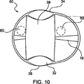
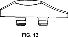
膝蓋構成要素50の他の実施形態を図10〜13に示す。この実施形態は、前述の多くの特徴を有するが、さらに上位から下位の方向に緩和部分52を含有する。(いくつかの実施形態においては、緩和部分52は上端部面34から下端部面36へ延在される。)図11に示されるように、緩和部分52は面16の中央領域56を二つの部分(例えば、内側と外側)に分けられる。緩和部分52は、凹面、平面、実質的に平面、又は若干ながら凹面であってよい。この大まかな目的は、欠損された接面と共に仕切りを設けることであり、緩和部分52と、大腿構成要素の膝蓋溝との間で最小限の接触が生じるか、少しの接触もない。この設計は、一定の制約パターンが利用可能な可動域を通じて大腿構成要素と共に存在するように、関節面の配置を設ける。
Other embodiments of the
本質において、緩和部分52は、屈曲の最初から最後まで(又は実質的に屈曲の最初から最後まで)二つの接触断片60を提供するために、構成要素10の頂部領域が取り除かれた物質である。緩和部分52の製作は、頂部の起伏と称することができる。(この概念は、屈曲の間、大腿構成要素との接触を持続する二つの断片を有する頚骨の挿入箇所と類似している。)断片60は、制約パターンが同様の状態で継続されるため、屈曲時、互いに比較的内側−外側の距離を一定に保つことが好ましい。これは、前大腿部の突縁及び大腿構成要素の顆内域の屈曲域にわたって一定の制約を持続するのに役立つ。緩和部分52は、接することなく、滑車溝に沿って乗っている。構成要素50に設けられた頂部の起伏の量は変化することができ、望ましい設計によって決まる。上記に述べられた“クランク”問題防止のために、最上及び最下面(34及び36)において増大された頂部の起伏部分が設けられる。これらの増大された頂部の起伏部分は、本質的に上述の欠損部分32であり、単により顕著な方法で随意に提供されているだけである。図10〜13に同様に示されるのは、実質的に軸対称な部分18、ファセット面30、及び(僅かな又は大きい縁半径を有し得る)欠損部分32である。これらの面は、前述のように形成され得る。他の実施形態において、これらの面は二つの部分から成る接触パッチとして存在するわけではなく、せん断力及び制御された移行を低減させる適切な力平衡を可能とする。
In essence, the
図14に示す他の実施形態では、より深い屈曲作用において接触領域を最大にするために構成要素50の輪郭は改良されてもよい。ファセット面は、図4〜6のインプラントと同様に関節を成し、これらのインプラントと同類であることから、関節を成したファセット面はせん断力の軽減を助長する。さらに、内側頂部の起伏端部は初期の屈曲において内側の接触領域を増やすために改良されてもよい。例えば、図14に示すように、全ての軸及び寸法は図10に示す設計と同じ状態であり得るが、インプラント50の上層部分62における接触断片がより大きな関節面となるように若干改良されてもよい。要するに、図10が図14と重ね合わせられるとわかるように、上層部分62にはより大きな隅部が設けられ、又は上層部分62にてより大きな境界面を設けるために延在された外形を有する。
In other embodiments shown in FIG. 14, the contour of
図15に示すさらなる実施形態では、緩和部分52は幅が広げられ、(図示された実施形態では、内側縁20側により延在されているが)内側縁20と外側縁22とにより延在される。本実施形態では、平面な、又は実質的に平面な緩和部分52を有しておらず、その代わりに僅かながら凸状である。既に述べたように、これは本発明の範囲内でまだ緩和部分52と考えられる。この設計は、交差する保持手法に関連して特定の使用を見出し得る。緩和部分52の幅は、大腿構成要素の顆部間の距離と同じと成り得る。増大した緩和部分を設けることは接触域が極小化されるが、場合によっては必要と成り得る。図示されていないが、緩和部分52は図示されているものと比べてより狭くもなり得る。これは接触域を最大にするが、移植不良に対する感受性を犠牲にし得る。必要な手段のための適当なバランスは、患者の需要によって上述した設計の様々な特徴を組み合わせることにより成し遂げることできる。
In a further embodiment shown in FIG. 15, the
本発明のさらなる実施態様に係るさらなる実施形態では、楕円形凸状の膝蓋構成要素70を提供する。図16及び17に楕円形の形状を有する、凸状の膝蓋構成要素70が示されるが、任意の適切な形状が本発明の範囲内である。本実施形態の構成要素70は、膝蓋骨と大腿構成要素に対して連接する第二の面74とを係合する第一の面72を有する。第一の面72は、上述した実施形態の第一の面と同じような特徴を有し得る。第二の面74は、凸状の関節面76を有する形状である。面76は、円弧を備えた線が軸についてスウィープされること(即ち、スウィープされた円弧)を規定する。楕円形凸状の膝蓋構成要素を構築するのに用いることができる幾何学的形状の例として、図20に示す。この例では、スウィープ軸(sweep axis)が一つの平面に規定され、関節面の輪郭はスウィープ軸についてスウィープ、又は“突出”される。この“突出された面”又は“スウィープされたシート”は、構成要素70の関節面76を定義するのに用いることができる。関節面76は、いずれもが第二の面と交差しない一つ以上の軸について輪郭形状をスウィープさせることによって形成され得る。(これは、図21に図示されているような、ボタン形又はドーム形の膝蓋を設計する際に用いられる典型的な手法とは区別される。)凸状の円弧又はスウィープされた輪郭形状の半径は、約50〜250mmに、とりわけ半径が100mmであるとき有用である。さらに、凸状の関節面76は複数の軸から構成することができ、例えば、異なる屈曲角度に関する異常回転の感度の総計を変化させるのに中心域が上部及び下部と異なる半径に成り得る。
In a further embodiment according to a further embodiment of the present invention, an elliptical
一定の滑車形状が必要とされることから、構成要素70は、大腿滑車溝の横断面を選択し、膝蓋の関節表面前方(反対側)の実質的内側−外側軸の周辺に大腿滑車溝の横断面をスウィープ若しくは突出し、サジタル平面(sagittal plane)の周りで切断された際、凸状の関節面が形成することによって設計することができる。大きな凸面半径が用いられると、背面の境界面におけるせん断力/応力が非常に軽減され得る。関節面が凹面又は平らではないことから、異常回転(スピン)に対する感受性は低減される。
Since a constant pulley shape is required, the
ドーム形又はボタン形の構成要素が受けるせん断力と楕円形凸状の膝蓋構成要素70が受けるせん断力とを比較した例が図18及び19に示される。それぞれの設計における接触ベクトルが矢印“A”および“B”によって示される。これは大腿構成要素から延在される力の方向である。(骨/構成要素境界面から測定されるか、又は図23によって定義された解剖学的基準座標系を用いて測定された)垂直力は、N(図18ではN1、図19ではN2)によって表される。接触力ベクトル(A又はB)の端部と垂直力(N1又はN2)の端部との間の距離はせん断力要素であり、S1及びS2によって示される。図18ではドーム形/ボタン形構成要素が受けるせん断力“S1”を示し、図19では楕円形凸状の構成要素70が受けるせん断力“S2”を示す。楕円形凸状の構成要素が受ける接触力“B”は第一の面にほぼ垂直であり、この設計ではせん断力が大幅に軽減されることを意味する。要するに、凸面の半径を変化させることにより、せん断力の軽減と異常回転の感受性とのバランスが保たれ得る。この設計は、真っ直ぐではなく、又は僅かながらアーチ形である大腿滑車溝にとって凹状又は平面設計より最適でもある。
An example comparing the shear force experienced by a dome-shaped or button-shaped component with the shear force experienced by an elliptical
図17に戻ると、上端部面78および下端部面80は欠損部分32を同様に有し得る。上述のように、欠損部分32は、構成要素70が滑車溝と顆部との間の転移を促進させ、屈曲と伸長との間の転移において打撃若しくはクランクを防ぐのを助ける。この例は、欠損部分が丸い、又は角のある形状と成り得ることも同様に示す。記載された全実施形態における基本目的は、単に構成要素の端部から材質を除去することである。図18と図19との比較で示すように、凸状構成要素70の設計には、上述したドーム形/ボタン形膝蓋の設計より多くの素材体積が含有されてもよい。図19の矢印“B”が示す部分は、図18の矢印“A”が示す部分よりも多くの素材が含有され、よってその域においてより耐久性を有する。要するに、楕円形凸状膝蓋の設計は特定の領域における過度の磨耗及び骨折を防ぐために有用と成り得る。
Returning to FIG. 17, the
前述した膝蓋構成要素は、従来の外科技術を用いて埋め込まれてもよい。例えば、膝蓋骨は従来、脛骨及び大腿の切断が行われた後、試験的配置の前に準備されていた。一旦適切な膝蓋構成要素が選定されると、膝蓋は適切な深さ及び部位にリーミングされるべきである。(技術的に解されるように、インプラントがオンセット型かインセット型かにより異なるリーマー機器及び技法が用いられるか決まる。)切断後に残った骨の量を断定するために膝蓋全体の厚さは測定するべきであり、それから膝蓋は切除又は面が仕上げ直される。そして、釘穴を開けるために膝蓋釘ドリルを用いることができる。次いで、自然の膝蓋の一部分が準備されたら、適切な膝蓋構成要素が埋め込まれる。 The aforementioned patella components may be implanted using conventional surgical techniques. For example, the patella has traditionally been prepared after tibia and thigh cuts and prior to trial placement. Once the appropriate patella component is selected, the patella should be reamed to the appropriate depth and site. (As technically understood, different reamer devices and techniques are used depending on whether the implant is onset or inset.) Total patellar thickness to determine the amount of bone remaining after cutting Should be measured, and then the patella is resected or refinished. A patella nail drill can then be used to open the nail hole. The appropriate patella component is then implanted once a portion of the natural patella is prepared.
本発明及び特許請求の範囲の技術的範囲又は精神から逸脱することなく、図示された、及び上記に列挙された構造及び手法に関して、変更及び改良、追加及び削除することができる。 Changes and modifications, additions and deletions may be made to the structures and techniques illustrated and listed above without departing from the scope or spirit of the present invention and claims.
10、50、70 膝蓋構成要素
12 膝蓋構成要素本体
14、72 第一の表面
16、74 第二の表面
18 実質的に軸対称な部分
20 内端面
22 外端面
24 湾曲部位
26 先端部(頂部)
28 小片
30 ファセット面
32 欠損部分
34 上端部面
36 下端部面
38 縁半径
52 緩和部分
56 中央領域
60 接触断片
62 構成要素50の上層部分
76 関節面
100 大腿四頭筋腱
101 膝蓋
104 膝蓋腱
107 第一の接続領域
108 第二の接続領域
A、B 接触力ベクトル
N、N1、N2 垂直力
S1、S2 せん断力
10, 50, 70
28
Claims (8)
(i)使用される大腿骨構成要素と接する、前記内端面から前記外端面へ延在する実質的に軸対称な部分と、
(ii)前記実質的に軸対称な部分から延在し、使用される大腿骨構成要素と接する一つ以上のファセット面と、
(iii)緩和部分であって、該緩和部分がなければ前記実質的に軸対称な部分の頂部が在るだろう場所に位置する前記緩和部分と、
をさらに備える膝蓋構成要素であって、
前記一つ以上のファセット面が前記実質的に軸対称な部分の両外側に延在すること特徴とする膝蓋構成要素。A patella component main portion comprising: (a) a first surface engaged with a natural patella used; and (b) a second surface receiving a femoral component used. The second surface has an upper end surface, a lower end surface, an inner end surface, and an outer end surface, and the second surface is
(I) a substantially axisymmetric portion extending from the inner end surface to the outer end surface in contact with the femoral component used;
(Ii) the substantially extends from the axial symmetric portion, and one or more facets in contact with femoral components used,
(Iii) a relaxation portion, wherein the relaxation portion is located where there would be a top of the substantially axisymmetric portion without the relaxation portion;
A patella component further comprising:
The patella component, wherein the one or more facet surfaces extend on both outer sides of the substantially axisymmetric portion .
をさらに備えることを特徴とする請求項1に記載の膝蓋構成要素。 (Iv) while being bent and stretched, in order to allow a smooth transition on the femoral component, the upper end surface, lower end surface, or one or more defective portions in both sides,
The patella component according to claim 1, further comprising:
(a)オンセット型構成要素に関して、前記膝蓋骨/膝蓋構成要素の境界面にほぼ垂直な線、
(b)インセット型構成要素に関して、膝蓋骨に設けられた軸にほぼ平行な線、又は
(c)大腿四頭筋腱が前記膝蓋の上極に付随された箇所と、膝蓋腱が前記膝蓋の下極に付随された箇所との間に線として定義づけられた基準線にほぼ垂直な線、
のうちの一つから0〜30度であることを特徴とする請求項1〜6のいずれか一項に記載の膝蓋構成要素。A contact vector, which is a vector of forces acting on the second surface from the femoral component ,
(A) for an onset component, a line substantially perpendicular to the patella / patella component interface;
(B) With respect to the inset-type component, a line substantially parallel to the axis provided on the patella, or (c) a location where the quadriceps tendon is attached to the upper pole of the patella, and the patella tendon is located on the patella A line approximately perpendicular to the reference line defined as a line between the point attached to the lower pole,
The patella component according to any one of claims 1 to 6 , wherein the patella component is 0 to 30 degrees.
(a)オンセット型構成要素に関して、前記膝蓋骨/膝蓋構成要素の境界面にほぼ垂直な線、
(b)インセット型構成要素に関して、膝蓋骨に設けられた軸にほぼ平行な線、又は
(c)大腿四頭筋腱が前記膝蓋の上極に付随された箇所と、膝蓋腱が前記膝蓋の下極に付随された箇所との間に線として定義づけられた基準線にほぼ垂直な線、
のうちの一つから0〜5度であることを特徴とする請求項1〜6のいずれか一項に記載の膝蓋構成要素。A contact vector, which is a vector of forces acting on the second surface from the femoral component ,
(A) for an onset component, a line substantially perpendicular to the patella / patella component interface;
(B) With respect to the inset-type component, a line substantially parallel to the axis provided on the patella, or (c) a location where the quadriceps tendon is attached to the upper pole of the patella, and the patella tendon is located on the patella A line approximately perpendicular to the reference line defined as a line between the point attached to the lower pole,
The patella component according to any one of claims 1 to 6 , wherein the patella component is 0 to 5 degrees.
Applications Claiming Priority (7)
| Application Number | Priority Date | Filing Date | Title |
|---|---|---|---|
| US76129706P | 2006-01-23 | 2006-01-23 | |
| US76129606P | 2006-01-23 | 2006-01-23 | |
| US76129806P | 2006-01-23 | 2006-01-23 | |
| US60/761,298 | 2006-01-23 | ||
| US60/761,297 | 2006-01-23 | ||
| US60/761,296 | 2006-01-23 | ||
| PCT/US2007/002041 WO2007102951A2 (en) | 2006-01-23 | 2007-01-23 | Patellar components |
Publications (3)
| Publication Number | Publication Date |
|---|---|
| JP2009523569A JP2009523569A (en) | 2009-06-25 |
| JP2009523569A5 JP2009523569A5 (en) | 2012-05-31 |
| JP5128497B2 true JP5128497B2 (en) | 2013-01-23 |
Family
ID=38475327
Family Applications (1)
| Application Number | Title | Priority Date | Filing Date |
|---|---|---|---|
| JP2008551485A Expired - Fee Related JP5128497B2 (en) | 2006-01-23 | 2007-01-23 | Patellar component |
Country Status (7)
| Country | Link |
|---|---|
| US (1) | US8142509B2 (en) |
| EP (2) | EP3549553A3 (en) |
| JP (1) | JP5128497B2 (en) |
| CN (2) | CN101404955B (en) |
| AU (1) | AU2007222102B2 (en) |
| CA (1) | CA2637611C (en) |
| WO (1) | WO2007102951A2 (en) |
Families Citing this family (50)
| Publication number | Priority date | Publication date | Assignee | Title |
|---|---|---|---|---|
| KR101406415B1 (en) | 2005-07-15 | 2014-06-19 | 미셀 테크놀로지즈, 인코포레이티드 | Polymer coatings containing drug powder of controlled morphology |
| WO2007011708A2 (en) | 2005-07-15 | 2007-01-25 | Micell Technologies, Inc. | Stent with polymer coating containing amorphous rapamycin |
| GB2461149B (en) * | 2005-12-28 | 2010-05-26 | Derek James Wallace Mcminn | Improvements in or relating to knee prosthesis |
| EP3549553A3 (en) | 2006-01-23 | 2020-01-08 | Smith & Nephew, Inc | Patellar components |
| AU2007243268B2 (en) | 2006-04-26 | 2013-06-13 | Micell Technologies, Inc. | Coatings containing multiple drugs |
| WO2008042909A2 (en) * | 2006-10-02 | 2008-04-10 | Micell Technologies Inc. | Surgical sutures having increased strength |
| JP5603598B2 (en) | 2007-01-08 | 2014-10-08 | ミセル テクノロジーズ、インコーポレイテッド | Stent with biodegradable layer |
| US11426494B2 (en) | 2007-01-08 | 2022-08-30 | MT Acquisition Holdings LLC | Stents having biodegradable layers |
| BRPI0910969B8 (en) | 2008-04-17 | 2021-06-22 | Micell Technologies Inc | device |
| US8092544B2 (en) * | 2008-06-30 | 2012-01-10 | Depuy Products, Inc. | Implantable patella component having a thickened superior edge |
| US7972383B2 (en) * | 2008-06-30 | 2011-07-05 | Depuy Products, Inc. | Implantable patella component having a thickened superior edge |
| JP2011528275A (en) | 2008-07-17 | 2011-11-17 | ミセル テクノロジーズ,インク. | Drug delivery medical device |
| US20100222782A1 (en) * | 2009-02-27 | 2010-09-02 | Howmedica Osteonics Corp. | Spot facing trochlear groove |
| US8480753B2 (en) * | 2009-02-27 | 2013-07-09 | Howmedica Osteonics Corp. | Spot facing trochlear groove |
| JP2012522589A (en) | 2009-04-01 | 2012-09-27 | ミシェル テクノロジーズ,インコーポレイテッド | Covered stent |
| MX2011010409A (en) * | 2009-04-03 | 2012-01-20 | Ashland Licensing & Intellectu | Ultraviolet radiation curable pressure sensitive acrylic adhesive. |
| EP3366326A1 (en) | 2009-04-17 | 2018-08-29 | Micell Technologies, Inc. | Stents having controlled elution |
| EP2453834A4 (en) | 2009-07-16 | 2014-04-16 | Micell Technologies Inc | Drug delivery medical device |
| EP2531140B1 (en) | 2010-02-02 | 2017-11-01 | Micell Technologies, Inc. | Stent and stent delivery system with improved deliverability |
| EP2560576B1 (en) | 2010-04-22 | 2018-07-18 | Micell Technologies, Inc. | Stents and other devices having extracellular matrix coating |
| WO2012009684A2 (en) | 2010-07-16 | 2012-01-19 | Micell Technologies, Inc. | Drug delivery medical device |
| EP2595574B1 (en) | 2010-07-24 | 2017-05-03 | Zimmer, Inc. | Asymmetric tibial components for a knee prosthesis |
| US8764840B2 (en) | 2010-07-24 | 2014-07-01 | Zimmer, Inc. | Tibial prosthesis |
| US8591594B2 (en) | 2010-09-10 | 2013-11-26 | Zimmer, Inc. | Motion facilitating tibial components for a knee prosthesis |
| CA2810729C (en) * | 2010-09-10 | 2018-04-10 | Zimmer Gmbh | Femoral prosthesis with medialized patellar groove |
| CN103260553B (en) * | 2010-12-07 | 2015-11-25 | 捷迈有限公司 | Prosthetic patella |
| US8603101B2 (en) | 2010-12-17 | 2013-12-10 | Zimmer, Inc. | Provisional tibial prosthesis system |
| US9675399B2 (en) | 2011-02-14 | 2017-06-13 | Michael D. Ries | Patient specific implants and instrumentation for patellar prostheses |
| US8945135B2 (en) | 2011-02-14 | 2015-02-03 | Michael D. Ries | Patellar prostheses and instrumentation |
| WO2012166819A1 (en) | 2011-05-31 | 2012-12-06 | Micell Technologies, Inc. | System and process for formation of a time-released, drug-eluting transferable coating |
| WO2013012689A1 (en) | 2011-07-15 | 2013-01-24 | Micell Technologies, Inc. | Drug delivery medical device |
| US10188772B2 (en) | 2011-10-18 | 2019-01-29 | Micell Technologies, Inc. | Drug delivery medical device |
| EP3848005A3 (en) | 2011-11-18 | 2021-09-15 | Zimmer, Inc. | Tibial bearing component for a knee prosthesis with improved articular characteristics |
| AU2012341026B2 (en) | 2011-11-21 | 2015-01-29 | Zimmer, Inc. | Tibial baseplate with asymmetric placement of fixation structures |
| IN2014DN07145A (en) | 2012-01-30 | 2015-04-24 | Zimmer Inc | |
| EP2967803B1 (en) | 2013-03-12 | 2023-12-27 | Micell Technologies, Inc. | Bioabsorbable biomedical implants |
| US10130480B2 (en) | 2013-03-13 | 2018-11-20 | Howmedica Osteonics Corp. | Modular patella trials |
| KR102079613B1 (en) | 2013-05-15 | 2020-02-20 | 미셀 테크놀로지즈, 인코포레이티드 | Bioabsorbable biomedical implants |
| US9925052B2 (en) | 2013-08-30 | 2018-03-27 | Zimmer, Inc. | Method for optimizing implant designs |
| US9655727B2 (en) | 2013-12-12 | 2017-05-23 | Stryker Corporation | Extended patellofemoral |
| EP3352708B1 (en) | 2015-09-21 | 2020-07-22 | Zimmer, Inc. | Prosthesis system including tibial bearing component |
| ES2878003T3 (en) | 2017-03-10 | 2021-11-18 | Zimmer Inc | Tibial prosthesis with locking feature for a tibial bearing component |
| AU2018266322B2 (en) | 2017-05-12 | 2020-03-19 | Zimmer, Inc. | Femoral prostheses with upsizing and downsizing capabilities |
| AU2018203343B2 (en) | 2017-05-15 | 2023-04-27 | Howmedica Osteonics Corp. | Patellofemoral implant |
| US10940666B2 (en) | 2017-05-26 | 2021-03-09 | Howmedica Osteonics Corp. | Packaging structures and additive manufacturing thereof |
| US10893948B2 (en) | 2017-11-02 | 2021-01-19 | Howmedica Osteonics Corp. | Rotary arc patella articulating geometry |
| US11426282B2 (en) | 2017-11-16 | 2022-08-30 | Zimmer, Inc. | Implants for adding joint inclination to a knee arthroplasty |
| US10835380B2 (en) | 2018-04-30 | 2020-11-17 | Zimmer, Inc. | Posterior stabilized prosthesis system |
| WO2020092335A1 (en) * | 2018-10-29 | 2020-05-07 | Arthrosurface Incorporated | Articular surface implants with dimples |
| USD995790S1 (en) | 2020-03-30 | 2023-08-15 | Depuy Ireland Unlimited Company | Robotic surgical tool |
Family Cites Families (102)
| Publication number | Priority date | Publication date | Assignee | Title |
|---|---|---|---|---|
| US3878566A (en) | 1974-05-08 | 1975-04-22 | Richards Mfg Co | Patello-femoral prosthesis |
| US3927423A (en) | 1974-06-07 | 1975-12-23 | Alfred B Swanson | Patellar implant and method |
| US4007495A (en) | 1976-05-28 | 1977-02-15 | Frazier Calvin H | Patello-femoral prothesis |
| DE2703059C3 (en) | 1977-01-26 | 1981-09-03 | Sanitätshaus Schütt & Grundei, Werkstätten für Orthopädie-Technik, 2400 Lübeck | Knee joint endoprosthesis |
| US4094017A (en) | 1977-02-16 | 1978-06-13 | Larry Stanford Matthews | Knee joint prosthesis with patellar-femoral contact |
| US4151615A (en) * | 1977-06-29 | 1979-05-01 | Hall Thomas D | Prosthetic patello-femoral joint |
| DE2965891D1 (en) * | 1978-03-10 | 1983-08-25 | Biomedical Eng Corp | Improved joint endoprosthesis |
| US4470158A (en) * | 1978-03-10 | 1984-09-11 | Biomedical Engineering Corp. | Joint endoprosthesis |
| US4158894A (en) | 1978-03-13 | 1979-06-26 | Worrell Richard V | Patellar prosthesis and method of implanting the same |
| US4285070A (en) * | 1978-06-05 | 1981-08-25 | Minnesota Mining And Manufacturing Company | Prosthetic device |
| FR2445136A1 (en) * | 1978-12-27 | 1980-07-25 | Imbert Jean Claude | Total prosthetic replacement for femoro-patellar articulation - comprises convex patellar component with parallel fixing flanges and concave rail on femur over which it slides |
| US4207627A (en) | 1979-01-18 | 1980-06-17 | Cloutier Jean Marie | Knee prosthesis |
| US4221006A (en) | 1979-03-19 | 1980-09-02 | Bernard Gendelman | Balanced remote control |
| US4353135A (en) * | 1980-05-09 | 1982-10-12 | Minnesota Mining And Manufacturing Company | Patellar flange and femoral knee-joint prosthesis |
| FR2578451B1 (en) | 1985-03-05 | 1988-08-26 | Bertin & Cie | PROCESS AND DEVICE FOR THE DISPERSION OF ULTRA-FINE POWDERS |
| US4633862A (en) | 1985-05-30 | 1987-01-06 | Petersen Thomas D | Patellar resection sawguide |
| US5002547A (en) | 1987-02-07 | 1991-03-26 | Pfizer Hospital Products Group, Inc. | Apparatus for knee prosthesis |
| US4888021A (en) * | 1988-02-02 | 1989-12-19 | Joint Medical Products Corporation | Knee and patellar prosthesis |
| US5011496A (en) | 1988-02-02 | 1991-04-30 | Joint Medical Products Corporation | Prosthetic joint |
| US5035700A (en) | 1988-02-03 | 1991-07-30 | Pfizer Hospital Products Group, Inc. | Prosthetic knee joint with improved patellar component tracking |
| US4944756A (en) | 1988-02-03 | 1990-07-31 | Pfizer Hospital Products Group | Prosthetic knee joint with improved patellar component tracking |
| US4964867A (en) | 1989-02-03 | 1990-10-23 | Boehringer Mannheim Corp. | Patellar prosthesis |
| CH680646A5 (en) * | 1990-01-12 | 1992-10-15 | Sulzer Ag | |
| US5019104A (en) | 1990-01-16 | 1991-05-28 | Dow Corning Wright Corporation | Patellar prosthesis and method of making the same |
| US5197986A (en) | 1990-04-11 | 1993-03-30 | Mikhail Michael W E | Recessed patellar prosthesis |
| GB9018737D0 (en) | 1990-08-28 | 1990-10-10 | Goodfellow John W | Phosphetic patellar components |
| US5021061A (en) | 1990-09-26 | 1991-06-04 | Queen's University At Kingston | Prosthetic patello-femoral joint |
| US5330532A (en) | 1990-11-09 | 1994-07-19 | Chitranjan Ranawat | Knee joint prosthesis |
| US5222955A (en) | 1991-02-08 | 1993-06-29 | Mikhail Michael W E | Method for implanting a patellar prosthesis |
| US5180384A (en) | 1991-02-08 | 1993-01-19 | Mikhail Michael W E | Method for implanting a patellar prosthesis |
| US5100409A (en) | 1991-03-07 | 1992-03-31 | Dow Corning Wright Corporation | Shaping and trial reduction guide for implantation of femoral prosthesis and method of using same |
| US5098436A (en) | 1991-03-07 | 1992-03-24 | Dow Corning Wright Corporation | Modular guide for shaping of femur to accommodate intercondylar stabilizing housing and patellar track of implant |
| US5236462A (en) | 1991-04-23 | 1993-08-17 | Mikhail Michael W E | Metal-backed patellar prosthesis |
| US5395401A (en) | 1991-06-17 | 1995-03-07 | Bahler; Andre | Prosthetic device for a complex joint |
| GB9114603D0 (en) | 1991-07-05 | 1991-08-21 | Johnson David P | Improvements relating to patella prostheses |
| US5133758A (en) * | 1991-09-16 | 1992-07-28 | Research And Education Institute, Inc. Harbor-Ucla Medical Center | Total knee endoprosthesis with fixed flexion-extension axis of rotation |
| DE9116507U1 (en) * | 1991-09-24 | 1992-12-03 | Eska Medical Luebeck Medizintechnik Gmbh & Co, 2400 Luebeck, De | |
| US5480443A (en) | 1992-01-31 | 1996-01-02 | Elias; Sarmed G. | Artifical implant component and method for securing same |
| US5176684A (en) | 1992-02-20 | 1993-01-05 | Dow Corning Wright | Modular shaping and trial reduction guide for implantation of posterior-stabilized femoral prosthesis and method of using same |
| US5201773A (en) | 1992-04-23 | 1993-04-13 | Carideo Jr Joseph F | Articulating supracondylar suspension |
| FR2692137B1 (en) | 1992-06-16 | 1995-06-16 | Dev Implants Orthop Et Med | ROTULAR CUTTING DEVICE FOR LAYING A TOTAL KNEE PROSTHESIS. |
| DE4221006C2 (en) | 1992-06-26 | 1994-06-30 | S & G Implants Gmbh | Implant to replace a back patella part |
| EP0582514A1 (en) * | 1992-08-03 | 1994-02-09 | IMPLANTS ORTHOPEDIQUES TOUTES APPLICATIONS, S.A.R.L. dite: | Knee prosthesis |
| US5413604A (en) | 1992-12-24 | 1995-05-09 | Osteonics Corp. | Prosthetic knee implant for an anterior cruciate ligament deficient total knee replacement |
| FR2700260B1 (en) * | 1993-01-08 | 1995-04-14 | Bouvet Jean Claude | Artificial patellar part for knee prosthesis. |
| GB2277034B (en) | 1993-04-01 | 1997-02-26 | British Tech Group | Implantable prosthetic patellar components |
| GB9306898D0 (en) | 1993-04-01 | 1993-05-26 | Ang Swee C | Implantable prosthetic patellar components |
| CN2167688Y (en) * | 1993-07-30 | 1994-06-08 | 陈汉文 | Artificial kneecap joint |
| US5437676A (en) | 1994-01-27 | 1995-08-01 | Developpement D'implants Orthopediques Et Medicaux | Kneecap cutting device for the fitting of a total knee replacement |
| US5885298A (en) | 1994-02-23 | 1999-03-23 | Biomet, Inc. | Patellar clamp and reamer with adjustable stop |
| GB9405746D0 (en) * | 1994-03-23 | 1994-05-11 | Howmedica | Prosthetic patello femoral joint assembly |
| IL109344A (en) * | 1994-04-19 | 1998-02-22 | Mendes David | Prosthetic patella implant of the knee joint |
| US6159246A (en) | 1994-04-19 | 2000-12-12 | Mendes; David | Surgical method and tool for repairing a patella of the knee joint |
| FR2719762B1 (en) | 1994-05-13 | 1996-07-12 | Smith & Nephew Richards France | Trochlear implant for femoro-patellar prosthesis and its fitting instrumentation. |
| US5536271A (en) | 1994-06-02 | 1996-07-16 | Depuy, Inc. | Patella reaming system |
| US5549688A (en) | 1994-08-04 | 1996-08-27 | Smith & Nephew Richards Inc. | Asymmetric femoral prosthesis |
| US5486177A (en) | 1994-12-20 | 1996-01-23 | Intermedics Orthopedics, Inc. | Patella planer with adjustable stop |
| US5593450A (en) * | 1995-02-27 | 1997-01-14 | Johnson & Johnson Professional, Inc. | Oval domed shaped patella prosthesis |
| US5520692A (en) | 1995-02-28 | 1996-05-28 | Wright Medical Technology, Inc. | Adjustable depth patella recessing guide and method |
| GB2301032B (en) | 1995-04-07 | 1999-10-06 | David Giorgio Mendes | Prosthetic patella implant of the knee joint and reamer |
| US6077270A (en) | 1995-05-31 | 2000-06-20 | Katz; Lawrence | Method and apparatus for locating bone cuts at the distal condylar femur region to receive a femoral prothesis and to coordinate tibial and patellar resection and replacement with femoral resection and replacement |
| US5716360A (en) | 1995-06-30 | 1998-02-10 | U.S. Medical Products | Patella recession instrument and method for anatomically-shaped patellar prostheses |
| JPH09172384A (en) * | 1995-12-19 | 1997-06-30 | Sony Corp | Receiving device for am radio broadcasting |
| US5702467A (en) | 1996-06-12 | 1997-12-30 | Johnson & Johnson Professional, Inc. | Patellar resurfacing component |
| US5871540A (en) | 1996-07-30 | 1999-02-16 | Osteonics Corp. | Patellar implant component and method |
| US7468075B2 (en) | 2001-05-25 | 2008-12-23 | Conformis, Inc. | Methods and compositions for articular repair |
| FR2782633B1 (en) | 1998-09-01 | 2000-11-24 | Daniel Noyer | ANCILLARY JOINT PREPARATION MATERIAL WHEN PLACING A PROSTHESIS |
| US6277121B1 (en) | 1998-09-09 | 2001-08-21 | Brian D. Burkinshaw | Patella reaming system |
| US5941884A (en) | 1998-10-09 | 1999-08-24 | Osteonics Corp. | Patella preparation apparatus and method |
| US6106529A (en) | 1998-12-18 | 2000-08-22 | Johnson & Johnson Professional, Inc. | Epicondylar axis referencing drill guide |
| US6146423A (en) | 1999-01-28 | 2000-11-14 | Implex Corporation | Patella replacement apparatus |
| US6712856B1 (en) | 2000-03-17 | 2004-03-30 | Kinamed, Inc. | Custom replacement device for resurfacing a femur and method of making the same |
| US6709460B2 (en) | 2000-03-21 | 2004-03-23 | Alan C. Merchant | Patellar bearing implant |
| US7713305B2 (en) | 2000-05-01 | 2010-05-11 | Arthrosurface, Inc. | Articular surface implant |
| US6602292B2 (en) | 2001-03-06 | 2003-08-05 | Centerpulse Orthopedic Inc. | Mobile bearing patella prosthesis |
| US20030033018A1 (en) | 2001-08-07 | 2003-02-13 | Merchant Alan C. | Patello-femoral joint arthroplasty |
| US20030120346A1 (en) | 2001-08-07 | 2003-06-26 | James Mercinek | Patellar prosthetic arrangement and associated surgical method |
| FR2831426B1 (en) * | 2001-10-30 | 2004-07-16 | Tornier Sa | JOINT IMPLANT AND KNEE PROSTHESIS INCORPORATING SUCH AN IMPLANT |
| DE10159659A1 (en) | 2001-12-05 | 2003-06-26 | Bayer Cropscience Ag | Herbicides based on substituted carboxylic acid anilides |
| US6589248B1 (en) | 2002-01-29 | 2003-07-08 | Joe L. Hughes | Patellar alignment device |
| PT1480582E (en) | 2002-02-14 | 2012-10-02 | Biomet Spain Orthopaedics S L | Patello-femoral joint replacement |
| EP2359775B1 (en) | 2002-02-20 | 2012-12-26 | Zimmer, Inc. | Knee arthroplasty prosthesis |
| GB2386558B (en) * | 2002-03-20 | 2005-09-14 | Sheo B Tibrewal | Apparatus for patella replacement |
| US6866667B2 (en) | 2002-09-03 | 2005-03-15 | Symmetry Medical, Inc. | Patellar milling clamp |
| US6800094B2 (en) | 2003-01-21 | 2004-10-05 | Zimmer Technology, Inc. | Mobile bearing patellar prosthesis with orbital translation |
| US20040162561A1 (en) | 2003-02-13 | 2004-08-19 | Howmedica Osteonics Corp. | Modular patella instrument |
| US6916341B2 (en) | 2003-02-20 | 2005-07-12 | Lindsey R. Rolston | Device and method for bicompartmental arthroplasty |
| AU2003904379A0 (en) | 2003-08-18 | 2003-08-28 | David John Wood | Two thirds prosthetic arthroplasty |
| CN2681706Y (en) * | 2004-03-09 | 2005-03-02 | 张翀 | Artificial joint prosthesis of patella-femur joint |
| US20090036993A1 (en) | 2004-04-22 | 2009-02-05 | Robert Metzger | Patellar implant |
| EP1591075B1 (en) | 2004-04-27 | 2008-03-19 | BrainLAB AG | Method and device for planning knee implants |
| US20070162142A1 (en) | 2005-06-15 | 2007-07-12 | Vitruvian Orthopaedics, Llc | Knee surgery method and apparatus |
| GB0526385D0 (en) | 2005-12-28 | 2006-02-08 | Mcminn Derek J W | Improvements in or relating to knee prosthesis |
| EP3549553A3 (en) | 2006-01-23 | 2020-01-08 | Smith & Nephew, Inc | Patellar components |
| AU2007212033B2 (en) | 2006-02-06 | 2014-01-23 | Conformis, Inc. | Patient selectable joint arthroplasty devices and surgical tools |
| US7691149B2 (en) | 2006-05-15 | 2010-04-06 | Biomet Manufacturing Corp. | Porous titanium modular revision patella system |
| ES2337712T3 (en) | 2006-10-12 | 2010-04-28 | WALDEMAR LINK GMBH & CO. KG | MODULAR ROTULAR INSTRUMENTAL. |
| US7758651B2 (en) | 2006-10-18 | 2010-07-20 | Howmedica Osteonics Corp. | Mis patellar preparation |
| US7582118B2 (en) | 2007-02-06 | 2009-09-01 | Zimmer Technology, Inc. | Femoral trochlea prostheses |
| US8092544B2 (en) | 2008-06-30 | 2012-01-10 | Depuy Products, Inc. | Implantable patella component having a thickened superior edge |
| US7972383B2 (en) | 2008-06-30 | 2011-07-05 | Depuy Products, Inc. | Implantable patella component having a thickened superior edge |
| US8696754B2 (en) | 2008-09-03 | 2014-04-15 | Biomet Manufacturing, Llc | Revision patella prosthesis |
-
2007
- 2007-01-23 EP EP18208272.7A patent/EP3549553A3/en not_active Withdrawn
- 2007-01-23 CN CN200780010180XA patent/CN101404955B/en not_active Expired - Fee Related
- 2007-01-23 AU AU2007222102A patent/AU2007222102B2/en not_active Ceased
- 2007-01-23 JP JP2008551485A patent/JP5128497B2/en not_active Expired - Fee Related
- 2007-01-23 WO PCT/US2007/002041 patent/WO2007102951A2/en active Application Filing
- 2007-01-23 CA CA2637611A patent/CA2637611C/en not_active Expired - Fee Related
- 2007-01-23 CN CN201310308703.6A patent/CN103356309B/en not_active Expired - Fee Related
- 2007-01-23 EP EP07749224A patent/EP1981442A2/en not_active Withdrawn
- 2007-01-23 US US12/159,805 patent/US8142509B2/en active Active
Also Published As
| Publication number | Publication date |
|---|---|
| WO2007102951A2 (en) | 2007-09-13 |
| CN101404955A (en) | 2009-04-08 |
| JP2009523569A (en) | 2009-06-25 |
| EP3549553A2 (en) | 2019-10-09 |
| EP1981442A2 (en) | 2008-10-22 |
| US8142509B2 (en) | 2012-03-27 |
| CA2637611C (en) | 2015-11-17 |
| CA2637611A1 (en) | 2007-09-13 |
| WO2007102951A9 (en) | 2007-10-25 |
| US20080300689A1 (en) | 2008-12-04 |
| CN103356309A (en) | 2013-10-23 |
| CN103356309B (en) | 2015-11-25 |
| AU2007222102B2 (en) | 2013-09-26 |
| AU2007222102A1 (en) | 2007-09-13 |
| WO2007102951A3 (en) | 2008-02-21 |
| EP3549553A3 (en) | 2020-01-08 |
| CN101404955B (en) | 2013-08-21 |
Similar Documents
| Publication | Publication Date | Title |
|---|---|---|
| JP5128497B2 (en) | Patellar component | |
| AU2020200759B2 (en) | Cruciate-retaining knee prosthesis | |
| CN101522137B (en) | Posterior stabilized knee prosthesis | |
| RU2599212C2 (en) | Family of tibial prosthesis (versions) | |
| EP2635239B1 (en) | Prosthetic device with multi-axis dual bearing assembly | |
| EP1974696B1 (en) | Mobile bearing assembly having a non-planar interface | |
| ES2419661T3 (en) | Orthopedic prosthesis | |
| JP6033860B2 (en) | Retrostable orthopedic prosthesis assembly | |
| JP2009523569A5 (en) | ||
| US20120101585A1 (en) | Motion facilitating tibial components for a knee prosthesis | |
| CN103732188A (en) | Femoral component for a knee prosthesis with improved articular characteristics | |
| US20160206437A1 (en) | Ankle Joint Replacement Implant With Bearing Interchangeability | |
| AU2016204556B2 (en) | Patellar components | |
| RU2588289C2 (en) | Knee joint prosthesis with preservation of cruciate ligament | |
| AU2011210760B2 (en) | Cruciate-retaining knee prosthesis | |
| AU2008201470A1 (en) | Mobile bearing assembly having a non-planar interface |
Legal Events
| Date | Code | Title | Description |
|---|---|---|---|
| A621 | Written request for application examination |
Free format text: JAPANESE INTERMEDIATE CODE: A621 Effective date: 20091224 |
|
| A131 | Notification of reasons for refusal |
Free format text: JAPANESE INTERMEDIATE CODE: A131 Effective date: 20111004 |
|
| A601 | Written request for extension of time |
Free format text: JAPANESE INTERMEDIATE CODE: A601 Effective date: 20111226 |
|
| A602 | Written permission of extension of time |
Free format text: JAPANESE INTERMEDIATE CODE: A602 Effective date: 20120106 |
|
| A601 | Written request for extension of time |
Free format text: JAPANESE INTERMEDIATE CODE: A601 Effective date: 20120203 |
|
| A602 | Written permission of extension of time |
Free format text: JAPANESE INTERMEDIATE CODE: A602 Effective date: 20120210 |
|
| A524 | Written submission of copy of amendment under article 19 pct |
Free format text: JAPANESE INTERMEDIATE CODE: A524 Effective date: 20120404 |
|
| TRDD | Decision of grant or rejection written | ||
| A01 | Written decision to grant a patent or to grant a registration (utility model) |
Free format text: JAPANESE INTERMEDIATE CODE: A01 Effective date: 20121002 |
|
| A01 | Written decision to grant a patent or to grant a registration (utility model) |
Free format text: JAPANESE INTERMEDIATE CODE: A01 |
|
| A61 | First payment of annual fees (during grant procedure) |
Free format text: JAPANESE INTERMEDIATE CODE: A61 Effective date: 20121031 |
|
| R150 | Certificate of patent or registration of utility model |
Free format text: JAPANESE INTERMEDIATE CODE: R150 Ref document number: 5128497 Country of ref document: JP Free format text: JAPANESE INTERMEDIATE CODE: R150 |
|
| FPAY | Renewal fee payment (event date is renewal date of database) |
Free format text: PAYMENT UNTIL: 20151109 Year of fee payment: 3 |
|
| R250 | Receipt of annual fees |
Free format text: JAPANESE INTERMEDIATE CODE: R250 |
|
| R250 | Receipt of annual fees |
Free format text: JAPANESE INTERMEDIATE CODE: R250 |
|
| R250 | Receipt of annual fees |
Free format text: JAPANESE INTERMEDIATE CODE: R250 |
|
| R250 | Receipt of annual fees |
Free format text: JAPANESE INTERMEDIATE CODE: R250 |
|
| R250 | Receipt of annual fees |
Free format text: JAPANESE INTERMEDIATE CODE: R250 |
|
| R250 | Receipt of annual fees |
Free format text: JAPANESE INTERMEDIATE CODE: R250 |
|
| R250 | Receipt of annual fees |
Free format text: JAPANESE INTERMEDIATE CODE: R250 |
|
| LAPS | Cancellation because of no payment of annual fees |