JP5125945B2 - Electronic device with display - Google Patents

Electronic device with display Download PDF

Info

Publication number
JP5125945B2
JP5125945B2 JP2008249153A JP2008249153A JP5125945B2 JP 5125945 B2 JP5125945 B2 JP 5125945B2 JP 2008249153 A JP2008249153 A JP 2008249153A JP 2008249153 A JP2008249153 A JP 2008249153A JP 5125945 B2 JP5125945 B2 JP 5125945B2
Authority
JP
Japan
Prior art keywords
display panel
polarizing plate
display
reflective polarizing
liquid crystal
Prior art date
Legal status (The legal status is an assumption and is not a legal conclusion. Google has not performed a legal analysis and makes no representation as to the accuracy of the status listed.)
Expired - Fee Related
Application number
JP2008249153A
Other languages
Japanese (ja)
Other versions
JP2010079087A (en
JP2010079087A5 (en
Inventor
君平 小林
一郎 大野
Current Assignee (The listed assignees may be inaccurate. Google has not performed a legal analysis and makes no representation or warranty as to the accuracy of the list.)
Casio Computer Co Ltd
Original Assignee
Casio Computer Co Ltd
Priority date (The priority date is an assumption and is not a legal conclusion. Google has not performed a legal analysis and makes no representation as to the accuracy of the date listed.)
Filing date
Publication date
Application filed by Casio Computer Co Ltd filed Critical Casio Computer Co Ltd
Priority to JP2008249153A priority Critical patent/JP5125945B2/en
Publication of JP2010079087A publication Critical patent/JP2010079087A/en
Publication of JP2010079087A5 publication Critical patent/JP2010079087A5/ja
Application granted granted Critical
Publication of JP5125945B2 publication Critical patent/JP5125945B2/en
Expired - Fee Related legal-status Critical Current
Anticipated expiration legal-status Critical

Links

Images

Landscapes

  • Liquid Crystal (AREA)
  • Devices For Indicating Variable Information By Combining Individual Elements (AREA)

Description

この発明は、画像の表示以外にミラーとしても使用できる表示部を備えた電子機器に関する。   The present invention relates to an electronic apparatus including a display unit that can be used as a mirror in addition to displaying an image.

携帯電話機等の表示部を備えた電子機器として、前記表示部を、液晶表示パネル等の表示パネルと、前記表示パネルの平面形状と実質的に同じ形状に形成され、前記表示パネルの観察側に配置された反射偏光板とにより構成し、前記表示部を、画像の表示以外に、電子機器の使用者の顔等を映して見るためのミラーとしても使用できるようにしたものがある(特許文献1参照)。
特開2004−246004号公報
As an electronic device equipped with a display unit such as a mobile phone, the display unit is formed in a display panel such as a liquid crystal display panel and a shape substantially the same as the planar shape of the display panel, and on the observation side of the display panel In addition to displaying an image, the display unit can be used as a mirror for viewing the face of a user of an electronic device (Patent Document). 1).
JP 2004-246004 A

しかし、上記従来の表示部を備えた電子機器は、ミラーとして使用することができる面積が狭い。   However, the electronic device including the conventional display unit has a small area that can be used as a mirror.

この発明は、表示パネルの画面エリアに対応する領域よりも外側の部分をミラーとして使用することができる電子機器を提供することを目的としたものである。 An object of the present invention is to provide an electronic apparatus that can use a portion outside a region corresponding to a screen area of a display panel as a mirror.

前記課題を解決するため、本発明の表示部を備えた電子機器の一態様は、所定の領域に画素が配列された表示パネルと、前記表示パネルよりも広い面積に形成されているとともに、前記表示パネルに対向するように配置された保護板と、前記表示パネルを収容するとともに、所定の開口部に前記保護板を嵌装する筐体と、前記保護板に貼付けられた2枚の反射偏光板と、を備え、前記2枚の反射偏光板のうちの、一方の反射偏光板は、前記保護板の前記筐体の外側に向いた外面に貼付けられ、他方の反射偏光板は、前記一方の反射偏光板と対向するように前記保護板の前記筐体の内側に向いた内面に貼付けられ、前記他方の反射偏光板の反射軸は、前記一方の反射偏光板の反射軸と実質的に平行である、ことを特徴とする。 In order to solve the above problems, an aspect of an electronic device including a display unit according to the present invention is formed with a display panel in which pixels are arranged in a predetermined region, a larger area than the display panel, and A protective plate arranged to face the display panel, a housing for housing the display panel and fitting the protective plate in a predetermined opening, and two pieces of reflected polarized light attached to the protective plate One of the two reflective polarizing plates is attached to the outer surface of the protective plate facing the outside of the housing, and the other reflective polarizing plate is the one of the reflective polarizing plates The protective plate is affixed to the inner surface of the protective plate facing the inside of the housing, and the reflection axis of the other reflection polarizer is substantially the same as the reflection axis of the one reflection polarizer. It is characterized by being parallel .

また、前記課題を解決するため、本発明の表示部を備えた電子機器の一態様は、機器ケースと、前記機器ケース内に配置された表示パネルと、前記機器ケースの前記表示パネルの観察側の面と対向する部分に、前記表示パネルの観察側の面よりも大きい形状に形成された表示窓と、前記表示パネルの観察側に配置され、前記表示パネルの観察側の面よりも大きい形状に形成され、且つ、互いに直交する2つの方向に透過軸と反射軸とをもち、入射光の互いに直交する2つの振動成分のうちの前記透過軸と平行な方向の振動成分の光を透過させ、前記反射軸と平行な方向の振動成分の光を反射する2枚の反射偏光板と、を備え、前記表示窓は、前記機器ケースに形成された開口部と、前記開口部に嵌装された表示部保護板を有し、前記2枚の反射偏光板のうちの、一方の反射偏光板は、前記表示部保護板の前記機器ケースの外側に向いた外面に貼付けられ、他方の反射偏光板は、前記一方の反射偏光板と対向するように前記表示部保護板の前記機器ケースの内側に向いた内面に貼付けられ、前記他方の反射偏光板の反射軸は、前記一方の反射偏光板の反射軸と実質的に平行である、ことを特徴とする。 In order to solve the above problems, an aspect of an electronic device including the display unit according to the present invention includes a device case, a display panel disposed in the device case, and an observation side of the display panel of the device case. A display window formed in a shape that is larger than the viewing side surface of the display panel, and a shape that is disposed on the viewing side of the display panel and that is larger than the viewing side surface of the display panel. And having a transmission axis and a reflection axis in two directions perpendicular to each other, and transmitting light of a vibration component in a direction parallel to the transmission axis of two vibration components perpendicular to each other of incident light. Two reflective polarizing plates that reflect light of vibration components in a direction parallel to the reflection axis, and the display window is fitted in the opening and formed in the device case. Display panel protective plate, Of the polarizing plates, one reflective polarizing plate is attached to the outer surface of the display unit protection plate facing the outside of the device case, and the other reflective polarizing plate faces the one reflective polarizing plate. Affixed to the inner surface of the display unit protection plate facing the inside of the device case, and the reflection axis of the other reflection polarizing plate is substantially parallel to the reflection axis of the one reflection polarizing plate. And

この発明によれば、表示パネルの画面エリアに対応する領域よりも外側の部分をミラーとして使用することができる。 According to the present invention, a portion outside the area corresponding to the screen area of the display panel can be used as a mirror.

(第1の実施形態)
図1〜図7はこの発明の第1の実施例を示しており、図1は表示部を備えた電子機器の使用状態における正面図、図2は前記電子機器の図1のII−II線に沿う拡大断面図である。
(First embodiment)
1 to 7 show a first embodiment of the present invention. FIG. 1 is a front view of an electronic device equipped with a display portion in use, and FIG. 2 is a II-II line of the electronic device in FIG. FIG.

この実施例の電子機器は、折りたたみ型の携帯電話機1であり、その機器ケースは、本体ケース2と、前記本体ケース2の一端に設けられたヒンジ部4に支持され、図1のように本体ケース2の外方に張出した開状態と、前記本体ケース2の上に重ねられた閉状態とに開閉回動される蓋ケース3とからなっている。   The electronic device of this embodiment is a foldable mobile phone 1, and the device case is supported by a main body case 2 and a hinge portion 4 provided at one end of the main body case 2, as shown in FIG. The lid case 3 is opened and closed and rotated between an open state projecting outward from the case 2 and a closed state superimposed on the main body case 2.

前記本体ケース2には、その前面(蓋ケース3の重なり面)に、キーボード部5とマイク部6が設けられており、この本体ケース2内に、制御部及び電源部等(図示せず)が収容されている。   The main body case 2 is provided with a keyboard portion 5 and a microphone portion 6 on the front surface (the overlapping surface of the lid case 3). In the main body case 2, a control portion, a power supply portion, and the like (not shown) Is housed.

また、前記蓋ケース3には、その前面(折りたたみ時に本体ケース2の前面に対向する面)に、表示部7を形成するための表示窓8が設けられ、さらに、この蓋ケース3の先端に近い部分の前面にスピーカ部11が設けられており、この蓋ケース3内に、前記表示部7を構成する表示パネル12が配置されている。   The lid case 3 is provided with a display window 8 for forming the display unit 7 on the front surface (the surface facing the front surface of the main body case 2 when folded). A speaker unit 11 is provided on the front surface of a near portion, and a display panel 12 constituting the display unit 7 is arranged in the lid case 3.

前記表示パネル12は、例えば透過型の液晶表示パネルであり、その内部構造は図示しないが、予め定めた間隙を設けて対向配置され、画面エリア13を囲む枠状のシール材16を介して接合された観察側とその反対側の一対の透明基板14,15と、これらの基板14,15の互いに向き合う内面それぞれに設けられ、互いに対向する領域により複数の画素をマトリックス状に配列させて形成する透明電極と、前記一対の基板14,15間の間隙の前記シール材16で囲まれた領域に封入された液晶層と、前記一対の基板14,15の外面にそれぞれ配置された観察側とその反対側の一対の偏光板(互いに直交する2つの方向に吸収軸と透過軸とをもち、入射光の互いに直交する2つの振動成分のうちの前記吸収軸と平行な方向の振動成分の光を吸収し、前記透過軸と平行な方向の振動成分の光を透過させる吸収偏光板)17,19とからなっている。   The display panel 12 is, for example, a transmissive liquid crystal display panel, and an internal structure thereof is not shown, but is opposed to each other with a predetermined gap and is joined via a frame-shaped sealing material 16 surrounding the screen area 13. And a pair of transparent substrates 14 and 15 on the opposite side to the observation side, and inner surfaces facing each other of these substrates 14 and 15, and a plurality of pixels are arranged in a matrix by areas facing each other. A transparent electrode, a liquid crystal layer sealed in a region surrounded by the sealing material 16 in a gap between the pair of substrates 14 and 15, an observation side disposed on the outer surface of the pair of substrates 14 and 15, respectively, A pair of polarizing plates on the opposite side (a vibration component having an absorption axis and a transmission axis in two directions orthogonal to each other and a direction parallel to the absorption axis of two vibration components of incident light orthogonal to each other) Absorbs light, which is the absorption polarizing plate) 17, 19 Metropolitan that transmits light of a vibration component of the transmission axis parallel to the direction.

なお、この液晶表示パネル12は、TFT(薄膜トランジスタ)をアクティブ素子としたアクティブマトリックス液晶表示パネルであり、前記一対の基板14,15のうちの観察側とは反対側の基板15の内面に、行方向及び列方向に配列させて形成された複数の画素電極と、これらの画素電極にそれぞれ接続された複数のTFTと、各行の複数のTFTにゲート信号を供給するための複数の走査線と、各列の複数のTFTにデータ信号を供給するための複数の信号線とが設けられ、観察側の基板14の内面に、前記複数の画素電極と対向する一枚膜状の対向電極と、前記複数の画素電極と前記対向電極とが互いに対向する領域からなる複数の画素にそれぞれ対応させて形成された赤、緑、青の3色のカラーフィルタとが設けられている。   The liquid crystal display panel 12 is an active matrix liquid crystal display panel using TFTs (thin film transistors) as active elements. The liquid crystal display panel 12 is arranged on the inner surface of the substrate 15 opposite to the observation side of the pair of substrates 14 and 15. A plurality of pixel electrodes arranged in a row direction and a column direction, a plurality of TFTs respectively connected to these pixel electrodes, a plurality of scanning lines for supplying gate signals to the plurality of TFTs in each row, A plurality of signal lines for supplying data signals to a plurality of TFTs in each column, a single film-like counter electrode facing the plurality of pixel electrodes on the inner surface of the substrate 14 on the observation side, There are provided color filters of three colors, red, green, and blue, which are formed so as to correspond to a plurality of pixels each composed of a region where the plurality of pixel electrodes and the counter electrode face each other.

また、前記複数の画素電極及び複数のTFTが設けられた反対側基板15の一端側には、観察側基板14の外方に突出する張出部15aが形成されており、この張出部15aに、前記複数の走査線及び複数の信号線と前記対向電極にそれぞれ接続された複数のドライバ接続端子(図示せず)が形成されている。   Further, an overhanging portion 15a protruding outward from the observation side substrate 14 is formed on one end side of the opposite substrate 15 provided with the plurality of pixel electrodes and the plurality of TFTs, and this overhanging portion 15a. In addition, a plurality of driver connection terminals (not shown) connected to the plurality of scanning lines and the plurality of signal lines and the counter electrode are formed.

そして、前記張出部15aには、前記対向電極に予め定めた電位の信号を印加し、さらに、前記複数の画素を行毎に選択して、各行の選択期間毎に、前記複数の走査線に順次ゲート信号を印加し、前記選択期間毎に、前記複数の信号線に、前記本体ケース2内の制御部から供給された表示データに対応したデータ信号を印加するドライバ素子20が、その複数の端子電極(図示せず)を前記複数のドライバ接続端子にそれぞれ接続して搭載されている。   A signal having a predetermined potential is applied to the overhanging portion 15a, the plurality of pixels are selected for each row, and the plurality of scanning lines are selected for each row selection period. A plurality of driver elements 20 that sequentially apply gate signals and apply data signals corresponding to display data supplied from the control unit in the main body case 2 to the plurality of signal lines for each of the selection periods. Terminal electrodes (not shown) are connected to the plurality of driver connection terminals, respectively.

なお、前記液晶表示パネル12は、前記液晶層の液晶分子を一対の基板14,15間において実質的に90度の捩れ角でツイスト配向させたTN型、液晶分子を一対の基板14,15間において180°〜270°の捩れ角でツイスト配向させたSTN型、液晶分子を基板面に対して実質的に垂直に配向させた垂直配向型、液晶分子分子長軸を一方向に揃えて基板面と実質的に平行に配向させた非ツイストの水平配向型、液晶分子をベンド配向させるベンド配向型のいずれでも、あるいは強誘電性または反強誘電性液晶表示パネルでもよい。 The liquid crystal display panel 12 includes a TN type liquid crystal molecule in which the liquid crystal molecules of the liquid crystal layer are twist-aligned between the pair of substrates 14 and 15 at a twist angle of substantially 90 degrees between the pair of substrates 14 and 15. STN type twisted with a twist angle of 180 ° to 270 °, a vertical alignment type in which liquid crystal molecules are aligned substantially perpendicular to the substrate surface, and a substrate in which the molecular long axes of liquid crystal molecules are aligned in one direction. Either a non-twisted horizontal alignment type that is aligned substantially parallel to the plane, a bend alignment type that bends liquid crystal molecules, or a ferroelectric or antiferroelectric liquid crystal display panel may be used.

さらに、前記液晶表示パネル12は、一対の基板14,15の内面それぞれに複数の画素を形成するための電極を設けたものに限らず、一対の基板14,15のいずれか一方の内面に、複数の画素を形成するための第1の電極と、それよりも液晶層側に前記第1の電極と絶縁して形成された複数の細長電極部を有する第2の電極とを設け、これらの電極間に横電界(基板面に沿う方向の電界)を生じさせて液晶分子の配向状態を変化させる横電界制御型のものでもよい。   Further, the liquid crystal display panel 12 is not limited to the one provided with electrodes for forming a plurality of pixels on the inner surfaces of the pair of substrates 14 and 15, respectively, A first electrode for forming a plurality of pixels and a second electrode having a plurality of elongated electrode portions formed on the liquid crystal layer side with insulation from the first electrode are provided. A lateral electric field control type of changing the alignment state of liquid crystal molecules by generating a lateral electric field (electric field in a direction along the substrate surface) between the electrodes may be used.

また、前記液晶表示パネル12は、一対の基板14,15とこれらの外面に配置された偏光板17,19との間の一方または両方に、表示品質を向上させるための位相差板等を配置したものでもよい。   In the liquid crystal display panel 12, a retardation plate or the like for improving display quality is disposed on one or both of the pair of substrates 14 and 15 and the polarizing plates 17 and 19 disposed on the outer surfaces thereof. You may have done.

そして、前記液晶表示パネル12は、その観察側の面(観察側偏光板17の外面)を、前記蓋ケース3の前面に設けられた表示窓8に対向させて前記蓋ケース3内に配置されている。   The liquid crystal display panel 12 is arranged in the lid case 3 with its observation side surface (outer surface of the observation side polarizing plate 17) facing the display window 8 provided on the front surface of the lid case 3. ing.

また、前記蓋ケース3内には、前記液晶表示パネル12の観察側とは反対側の面(反対側偏光板19の外面)に対向させて、前記液晶表示パネル12に向けて照明光を照射する面光源21が配置されている。   Further, the lid case 3 is irradiated with illumination light toward the liquid crystal display panel 12 so as to face the surface opposite to the observation side of the liquid crystal display panel 12 (the outer surface of the opposite polarizing plate 19). A surface light source 21 is disposed.

この面光源21は、前記液晶表示パネル12の画面エリア13よりも大きい矩形形状に形成された板状の透明部材からなり、その一端面に光を入射させる入射面22aが形成され、2つの板面のうちの前記液晶表示パネル12と対向する側の板面に前記入射面22aから入射した光の出射面22bが形成され、反対側の板面に前記入射面22aから入射した光を前記出射面22bに向けて反射する反射面22cが形成された導光板22と、この導光板22の入射面22aに対向させて配置されたLED(発光外オード)等からなる複数の発光素子23とによって構成されている。   The surface light source 21 is made of a plate-shaped transparent member formed in a rectangular shape larger than the screen area 13 of the liquid crystal display panel 12, and an incident surface 22a for allowing light to enter is formed on one end surface of the surface light source 21. A light exit surface 22b of light incident from the incident surface 22a is formed on a plate surface of the surface facing the liquid crystal display panel 12, and light incident from the incident surface 22a is formed on the opposite plate surface. A light guide plate 22 having a reflection surface 22c that reflects toward the surface 22b, and a plurality of light emitting elements 23 including LEDs (outside light emitting diodes) arranged to face the incident surface 22a of the light guide plate 22 It is configured.

前記蓋ケース3に設けられた表示窓8は、前記蓋ケース3の前面に、前記液晶表示パネル12の観察側の面よりも大きい矩形形状に形成された開口部9と、前記開口部9に嵌装された強化ガラス板またはアクリル樹脂板等からなる表示部保護板10とにより形成されている。   The display window 8 provided in the lid case 3 has an opening 9 formed on the front surface of the lid case 3 in a rectangular shape larger than the surface on the observation side of the liquid crystal display panel 12, and the opening 9 It is formed with the display part protection board 10 which consists of a tempered glass board or an acrylic resin board etc. which were fitted.

この実施例において、前記表示窓8は、前記蓋ケース3の前面のうちのスピーカ部11が設けられた先端側の部分を除く大部分の領域に、前記液晶表示パネル12の反対側基板15に形成された張出部15aを含む平面形状よりも大きい矩形形状に形成されている。   In this embodiment, the display window 8 is formed on a substrate 15 on the opposite side of the liquid crystal display panel 12 in the most part of the front surface of the lid case 3 except for the front end portion where the speaker unit 11 is provided. It is formed in a rectangular shape larger than the planar shape including the formed overhanging portion 15a.

さらに、前記液晶表示パネル12の観察側には、この液晶表示パネル12の観察側の面よりも大きい形状に形成された1枚の反射偏光板24が配置されている。この実施例において、前記反射偏光板24は、前記表示窓8を形成する表示部保護板10と実質的に同じ大きさ及び形状に形成されている。   Furthermore, on the viewing side of the liquid crystal display panel 12, a single reflective polarizing plate 24 formed in a shape larger than the viewing side surface of the liquid crystal display panel 12 is disposed. In this embodiment, the reflective polarizing plate 24 is formed in substantially the same size and shape as the display portion protection plate 10 that forms the display window 8.

図3は前記液晶表示パネル12と反射偏光板24の斜視図であり、前記反射偏光板24は、その板面に沿った互いに直交する2つの方向に透過軸25と反射軸26とをもち、入射光の互いに直交する2つの振動成分のうちの前記透過軸25と平行な方向の振動成分の光を透過させ、前記反射軸26と平行な方向の振動成分の光を鏡面反射する特性を有している。   FIG. 3 is a perspective view of the liquid crystal display panel 12 and the reflective polarizing plate 24. The reflective polarizing plate 24 has a transmission axis 25 and a reflection axis 26 in two directions perpendicular to each other along the plate surface. Of the two vibration components of the incident light that are orthogonal to each other, the light of the vibration component in the direction parallel to the transmission axis 25 is transmitted, and the light of the vibration component in the direction parallel to the reflection axis 26 is specularly reflected. doing.

この反射偏光板24は、前記表示部保護板10の蓋ケース3の内側に向いた内面に、前記透過軸25を、前記液晶表示パネル12の観察側偏光板17の透過軸18と実質的に平行にして配置され、前記保護板10の内面全体に貼付けられている。   The reflective polarizing plate 24 has an inner surface facing the inner side of the lid case 3 of the display unit protection plate 10, and the transmission axis 25 substantially corresponds to the transmission axis 18 of the observation side polarizing plate 17 of the liquid crystal display panel 12. It arrange | positions in parallel and is affixed on the whole inner surface of the said protective plate 10. FIG.

そして、内面に前記反射偏光板24が貼付けられた表示部保護板10は、前記蓋ケース3に設けられた開口部9に密に嵌装され、前記開口部9と前記反射偏光板24とからなる表示窓8を形成している。   And the display part protection board 10 by which the said reflective polarizing plate 24 was affixed on the inner surface is closely fitted by the opening part 9 provided in the said cover case 3, and from the said opening part 9 and the said reflective polarizing plate 24, A display window 8 is formed.

すなわち、前記携帯電話機1は、前記蓋ケース3に、この蓋ケース3内に配置された液晶表示パネル12及び面光源21と、前記蓋ケース3の前記液晶表示パネル12の観察側の面と対向する部分に、前記液晶表示パネル12の観察側の面よりも大きい形状に形成された表示窓8と、前記液晶表示パネル12の観察側の面よりも大きい形状に形成され、前記液晶表示パネル12の観察側に、前記保護板10の内面に貼付けて配置された反射偏光板24とからなる表示部7を形成したものである。   In other words, the mobile phone 1 faces the lid case 3, the liquid crystal display panel 12 and the surface light source 21 disposed in the lid case 3, and the observation side surface of the liquid crystal display panel 12 of the lid case 3. And a display window 8 formed in a shape larger than the viewing side surface of the liquid crystal display panel 12, and a shape larger than the viewing side surface of the liquid crystal display panel 12, and the liquid crystal display panel 12 The display part 7 which consists of the reflective polarizing plate 24 stuck and arrange | positioned on the inner surface of the said protective plate 10 is formed in the observation side.

この携帯電話機1は、前記液晶表示パネル12の観察側に前記反射偏光板24を配置した表示部7を備えているため、前記表示部7を、画像の表示以外に、携帯電話機1の使用者の顔等を映して見るためのミラーとしても使用することができる。   Since the mobile phone 1 includes the display unit 7 in which the reflective polarizing plate 24 is arranged on the observation side of the liquid crystal display panel 12, the display unit 7 is used for the user of the mobile phone 1 in addition to displaying images. It can also be used as a mirror for viewing the face of a person.

しかも、この携帯電話機1は、前記蓋ケース3に設けられた表示窓8と、前記反射偏光板24とを、前記液晶表示パネル12の観察側の面よりも大きい形状に形成しているため、前記表示部7のうちの前記液晶表示パネル12の画面エリア13に対応する領域よりも外側の部分をミラーとして使用することができる。   In addition, since the mobile phone 1 is formed with the display window 8 provided in the lid case 3 and the reflective polarizing plate 24 in a shape larger than the surface on the observation side of the liquid crystal display panel 12, A portion of the display unit 7 outside the region corresponding to the screen area 13 of the liquid crystal display panel 12 can be used as a mirror.

すなわち、この携帯電話機1は、蓋ケース3を図1のように開いて使用される。そして、前記面光源21は、前記蓋ケース3の開閉に対応して、蓋ケース3が開かれている間中、継続して点灯され、蓋ケース3が閉じられたときに消灯される。   That is, the cellular phone 1 is used with the lid case 3 opened as shown in FIG. The surface light source 21 is continuously lit while the lid case 3 is opened corresponding to the opening and closing of the lid case 3, and is turned off when the lid case 3 is closed.

また、前記本体ケース2内の制御部は、前記蓋ケース3が開かれているときに、前記キーボード部5の予め定めたキーまたは本体ケース2と蓋ケース3のいずれか一方の任意の部分に設けられた図示しないスイッチによる表示/ミラーの選択に対応して、表示が選択されたときに、前記液晶表示パネル12のドライバ素子20に画像信号に対応した表示データ(以下、画像データという)を供給し、ミラーが選択されたときに、前記ドライバ素子20に、前記液晶表示パネル12の画面エリア13の全体を黒にするための黒表示データを供給する。   Further, the control unit in the main body case 2 can be applied to a predetermined key of the keyboard unit 5 or any one of the main body case 2 and the lid case 3 when the lid case 3 is opened. When display is selected in response to selection of display / mirror by a switch (not shown) provided, display data corresponding to an image signal (hereinafter referred to as image data) is sent to the driver element 20 of the liquid crystal display panel 12. When the mirror is selected, black display data for making the entire screen area 13 of the liquid crystal display panel 12 black is supplied to the driver element 20.

すなわち、この携帯電話機においては、前記表示/ミラーの選択に対応して、前記液晶表示パネル12に、画像の表示と、画面エリア13の全体を黒にする黒表示とを選択的に行わせるようにしている。   That is, in this cellular phone, in response to the selection of the display / mirror, the liquid crystal display panel 12 is selectively made to display an image and a black display that makes the entire screen area 13 black. I have to.

なお、前記液晶表示パネル12は、前記複数の画素の電極間に電圧を印加しない無電界時の表示が明表示(白表示)であるノーマリーホワイト型表示パネルでも、前記無電界時の表示が暗表示(黒表示)であるノーマリーブラック型表示パネルでもよく、前記液晶表示パネル12がノーマリーホワイト型のときは、全ての画素の電極間に黒に対応した電圧を印加することにより画面エリア13の全体を黒にし、ノーマリーブラック型のときは、全ての画素の電極間に印加する電圧を実質的に0にすることにより画面エリア13の全体を黒にすることができる。 Note that the liquid crystal display panel 12 is a normally white display panel in which a non-electric field display without applying a voltage between the electrodes of the plurality of pixels is a bright display (white display). A normally black display panel that is a dark display (black display) may be used. When the liquid crystal display panel 12 is a normally white display panel, a screen area is obtained by applying a voltage corresponding to black between the electrodes of all pixels. In the case of a normally black type, the entire screen area 13 can be made black by setting the voltage applied between the electrodes of all the pixels to substantially zero.

そして、前記蓋ケース3を開いているときは、外部からの入射光のうちの前記表示窓8に入射した光が、前記表示部保護板10を透過して前記反射偏光板24に入射し、また、前記液晶表示パネル12に前記画像データに対応する画像を表示させたときは、前記面光源21から照射され、液晶表示パネル12の複数の画素により透過を制御されて前記液晶表示パネル12の画面エリア13から観察側に出射した光(以下、画像光という)が前記反射偏光板24に入射する。 When the lid case 3 is opened, light incident on the display window 8 out of incident light from the outside passes through the display unit protection plate 10 and enters the reflective polarizing plate 24. Further, when the allowed display an image corresponding to the image data to the liquid crystal display panel 12, the surface light source 21 is irradiated from the liquid crystal display panel 12 is controlling the transmittance of a plurality of pixels of the liquid crystal display panel 12 The light emitted from the screen area 13 to the observation side (hereinafter referred to as image light) enters the reflective polarizing plate 24.

また、前記液晶表示パネル12の画面エリア13の全体を黒にしたときは、前記面光源21から照射されて液晶表示パネル12に入射した光が前記液晶表示パネル12の観察側偏光板17により吸収され、前記液晶表示パネル12からは光が出射しない。   Further, when the entire screen area 13 of the liquid crystal display panel 12 is made black, the light irradiated from the surface light source 21 and incident on the liquid crystal display panel 12 is absorbed by the observation side polarizing plate 17 of the liquid crystal display panel 12. In addition, no light is emitted from the liquid crystal display panel 12.

図4は、前記液晶表示パネル12に黒を表示させたときの前記表示部7の光の経路を示す光線図、図5は、前記液晶表示パネル12に画像を表示させたときの前記表示部7の光の経路を示す光線図である。   FIG. 4 is a ray diagram showing a light path of the display unit 7 when black is displayed on the liquid crystal display panel 12, and FIG. 5 is a diagram showing the display unit when an image is displayed on the liquid crystal display panel 12. 7 is a ray diagram showing a light path of No. 7; FIG.

図4のように、前記液晶表示パネル12に黒を表示させたときは、前記液晶表示パネル12からは光が出射せず、外部から前記表示窓8に入射した光31だけが反射偏光板24に入射し、この光(非偏光の光)31のうちの前記反射偏光板24の透過軸25と平行な方向の振動成分の光31aが、この反射偏光板24を透過し、前記反射偏光板24の反射軸26と平行な方向の振動成分の光31bが、この反射偏光板24により反射されて前記表示窓8の全域から外部に出射する。   As shown in FIG. 4, when black is displayed on the liquid crystal display panel 12, no light is emitted from the liquid crystal display panel 12, and only the light 31 incident on the display window 8 from the outside is the reflective polarizing plate 24. Of the light (unpolarized light) 31, the light 31 a having a vibration component in a direction parallel to the transmission axis 25 of the reflective polarizing plate 24 passes through the reflective polarizing plate 24, and the reflective polarizing plate The light 31b of the vibration component in the direction parallel to the reflection axis 26 of 24 is reflected by the reflective polarizing plate 24 and is emitted from the entire area of the display window 8 to the outside.

なお、前記反射偏光板24を透過した光31aのうちの液晶表示パネル12の画面エリア13内に向かう光は、前記液晶表示パネル12の観察側偏光板17と液晶層とを透過して反対側の偏光板19により吸収され、他の部分に向かう光は、前記液晶表示パネル12の画面エリア13外の部分や、蓋ケース3の内面で散乱または吸収される。   Of the light 31a that has passed through the reflective polarizing plate 24, the light that goes into the screen area 13 of the liquid crystal display panel 12 passes through the observation-side polarizing plate 17 and the liquid crystal layer of the liquid crystal display panel 12 and is on the opposite side. The light that is absorbed by the polarizing plate 19 and travels to other parts is scattered or absorbed by the part outside the screen area 13 of the liquid crystal display panel 12 and the inner surface of the lid case 3.

そのため、前記液晶表示パネル12に黒を表示させたときは、前記表示窓8の全域を、外部からの入射光を前記反射偏光板24により反射するミラーとして使用することができる。   Therefore, when black is displayed on the liquid crystal display panel 12, the entire area of the display window 8 can be used as a mirror that reflects incident light from outside by the reflective polarizing plate 24.

また、図5のように、前記液晶表示パネル12に画像を表示させたときは、前記反射偏光板24に、外部から前記表示窓8に射した光31と、前記液晶表示パネル12の画面エリア13から出射した画像光32とが入射する。   As shown in FIG. 5, when an image is displayed on the liquid crystal display panel 12, the light 31 radiated from the outside to the display window 8 and the screen area of the liquid crystal display panel 12 are displayed on the reflective polarizing plate 24. The image light 32 emitted from 13 enters.

前記液晶表示パネル12の画面エリア13から出射した画像光32は、前記液晶表示パネル12の観察側偏光板17の透過軸18と平行な直線偏光であり、前記観察側偏光板17の透過軸18と前記反射偏光板24の透過軸25は実質的に平行であるため、前記画像光32は、前記反射偏光板24を高い透過率で透過し、さらに表示部保護板10を透過して前記表示窓8から外部に出射する。   The image light 32 emitted from the screen area 13 of the liquid crystal display panel 12 is linearly polarized light parallel to the transmission axis 18 of the observation side polarizing plate 17 of the liquid crystal display panel 12, and the transmission axis 18 of the observation side polarizing plate 17. Since the transmission axis 25 of the reflective polarizing plate 24 is substantially parallel, the image light 32 is transmitted through the reflective polarizing plate 24 at a high transmittance and further through the display unit protection plate 10 to display the display. The light is emitted from the window 8 to the outside.

そのため、このときは、前記表示窓8のうちの前記液晶表示パネル12の画面エリア13に対応する領域に画像が表示される。なお、このときも、外部から前記表示窓8に入射し、前記反射偏光板24により反射された光31bが前記表示窓8の全域から観察側外部に出射されるが、前記液晶表示パネル12の表示の輝度は、通常の使用環境における前記反射偏光板24により反射された光31bの強度に比べて充分高くなるように前記面光源21からの照明光の強度を設定してあるので、前記表示部7のうちの前記液晶表示パネル12の画面エリア13に対応する領域には、前記液晶表示パネル12に表示された画像が観察される。   Therefore, at this time, an image is displayed in an area corresponding to the screen area 13 of the liquid crystal display panel 12 in the display window 8. At this time, the light 31b incident on the display window 8 from the outside and reflected by the reflective polarizing plate 24 is emitted from the entire area of the display window 8 to the outside on the observation side. The intensity of the illumination light from the surface light source 21 is set so that the luminance of the display is sufficiently higher than the intensity of the light 31b reflected by the reflective polarizing plate 24 in a normal use environment. An image displayed on the liquid crystal display panel 12 is observed in an area corresponding to the screen area 13 of the liquid crystal display panel 12 in the unit 7.

そして、前記表示部7に画像を表示させたときも、前記液晶表示パネル12の画面エリア13に対応する領域以外の部分では、外部から前記表示窓8に入射した光31だけが反射偏光板24に入射し、この光31のうちの前記反射偏光板24により反射された光31bが前記表示窓8から外部に出射する。   Even when an image is displayed on the display unit 7, only the light 31 incident on the display window 8 from the outside is reflected by the reflective polarizing plate 24 in a portion other than the region corresponding to the screen area 13 of the liquid crystal display panel 12. Of the light 31, the light 31 b reflected by the reflective polarizing plate 24 is emitted from the display window 8 to the outside.

そして、前記表示窓8と前記反射偏光板24はそれぞれ、前記液晶表示パネル12の観察側の面よりも大きい形状に形成されているため、前記表示窓8のうちの前記液晶表示パネル12の画面エリア13に対応する領域以外の部分、つまり前記画面エリア11に対応する領域の全周を囲む枠状の部分を含めて、大きな面積のミラーとして使用することができる。 Since each of the display window 8 and the reflective polarizing plate 24 is formed in a shape larger than the viewing side surface of the liquid crystal display panel 12, the screen of the liquid crystal display panel 12 in the display window 8. A part other than the area corresponding to the area 13, that is, a frame-shaped part surrounding the entire circumference of the area corresponding to the screen area 11, can be used as a large area mirror.

さらに、上記実施例では、前記表示窓8を、前記蓋ケース3に設けられた開口部9と、この開口部9に嵌装された表示部保護板10とにより形成し、前記反射偏光板24を、前記表示部保護板10と実質的に同じ大きさ及び形状に形成しているため、前記液晶表示パネル12に黒を表示させたときに、前記表示窓8の全域をミラーとして使用することができる。また、前記液晶表示パネル12に画像を表示させたときには、前記表示窓8のうちの前記液晶表示パネル12の画面エリア13に対応する領域よりも外側の枠状部分をミラーとして使用することができる。   Further, in the above embodiment, the display window 8 is formed by the opening 9 provided in the lid case 3 and the display protection plate 10 fitted in the opening 9, and the reflective polarizing plate 24. Is formed in substantially the same size and shape as the display unit protection plate 10, so that the entire area of the display window 8 is used as a mirror when black is displayed on the liquid crystal display panel 12. Can do. Further, when an image is displayed on the liquid crystal display panel 12, a frame-shaped portion outside the region corresponding to the screen area 13 of the liquid crystal display panel 12 in the display window 8 can be used as a mirror. .

図6は、前記表示部7の表示窓全域をミラーとしたときの正面図、図7は、前記表示部7の画像を表示したときの正面図であり、これらの図において、並行斜線を施した部分は、ミラーとして使用される部分である。   FIG. 6 is a front view when the entire display window of the display unit 7 is used as a mirror, and FIG. 7 is a front view when an image of the display unit 7 is displayed. These parts are used as mirrors.

図6のように、前記液晶表示パネル12に黒を表示させたときは、前記表示窓8の全域をミラー33aとして使用できるため、この大面積のミラー33aに、使用者の顔34等を映して見ることができる。   As shown in FIG. 6, when black is displayed on the liquid crystal display panel 12, since the entire area of the display window 8 can be used as the mirror 33a, the user's face 34 and the like are projected on the large-area mirror 33a. You can see.

また、図7のように、前記液晶表示パネル12に画像35を表示させたときは、前記表示窓8のうちの前記液晶表示パネル12の画面エリア13に対応する領域よりも外側の枠状部をミラー33bとして使用できるため、この枠状のミラー33bに、使用者の顔の一部等を映して見ることができる。   Further, as shown in FIG. 7, when the image 35 is displayed on the liquid crystal display panel 12, the frame-shaped portion outside the area corresponding to the screen area 13 of the liquid crystal display panel 12 in the display window 8. Can be used as the mirror 33b, and a part of the user's face or the like can be seen on the frame-like mirror 33b.

また、上記実施例では、前記反射偏光板24を、前記表示部保護板10の内面に貼付けて配置しているため、前記反射偏光板24の汚れや損傷を防ぐとともに、前記表示窓8の表面を、前記保護板10の外面からなる平滑面にすることができる。ただし、前記反射偏光板24は、前記表示部保護板10の蓋ケース3外に対向する外面に貼付けて配置してもよい。   Moreover, in the said Example, since the said reflective polarizing plate 24 is affixed and arrange | positioned on the inner surface of the said display part protection board 10, while preventing the dirt and damage of the said reflective polarizing plate 24, the surface of the said display window 8 is provided. Can be a smooth surface formed by the outer surface of the protective plate 10. However, the reflective polarizing plate 24 may be disposed on the outer surface of the display unit protection plate 10 facing the outside of the lid case 3.

なお、上記実施例では、前記液晶表示パネル12に、画像の表示と、画面エリア13の全体を黒にする黒表示とを選択的に行わせるようにしているが、前記液晶表示パネル12に、前記画像の表示と、画面エリア13の全体を黒にする黒表示と、前記画面エリア13の全体を輝度の弱い白表示としてもよい。このようにすることにより、前記画面エリア13の領域の明るさを変えることができる。   In the above embodiment, the liquid crystal display panel 12 is selectively made to display an image and a black display that makes the entire screen area 13 black. The display of the image, black display that makes the entire screen area 13 black, and white display that has a low luminance may be made for the entire screen area 13. By doing so, the brightness of the area of the screen area 13 can be changed.

すなわち、前記液晶表示パネル12の画面エリア13の全体に輝度の弱い白を表示させ、前記液晶表示パネル12の画面エリア13から観察側に出射した白色光を前記反射偏光板24を透過させて外部に出射させることにより、明るさの強い外光のみを反射する通常の鏡とは異なる反射像を得ることができる。   That is, white with low luminance is displayed on the entire screen area 13 of the liquid crystal display panel 12, and white light emitted from the screen area 13 of the liquid crystal display panel 12 to the observation side is transmitted through the reflective polarizing plate 24 and externally. , It is possible to obtain a reflection image different from a normal mirror that reflects only external light with high brightness.

このように、前記液晶表示パネル12の画面エリア13の全体の表示を黒表示と白表示のいずれかに選択する場合、その選択は、使用者に行わせてもよいが、例えば外部の照度を光センサにより測定することにより自動的に行うことができる。   As described above, when the display of the entire screen area 13 of the liquid crystal display panel 12 is selected to be either black display or white display, the selection may be made by the user. This can be done automatically by measuring with an optical sensor.

(第2の実施形態)
図8はこの発明の第2の実施例を示す折りたたみ型携帯電話機の蓋部の断面図である。なお、この実施例において、上記第1の実施例に対応するものには図に同符号を付し、同一のものについてはその説明を省略する。
(Second Embodiment)
FIG. 8 is a cross-sectional view of a lid portion of a foldable mobile phone showing a second embodiment of the present invention. In this embodiment, parts corresponding to those in the first embodiment are given the same reference numerals in the drawings, and description of the same parts is omitted.

この実施例は、上記第1の実施例の携帯電話機1において、反射偏光板24を、液晶表示パネル12の観察側の面よりも大きく、表示部保護板10よりも小さい形状に形成し、この反射偏光板24を、前記保護板10の内面に、その周縁部を前記反射偏光板24の周囲に露出させて貼付け、さらに、前記保護板10の内面の周縁部に、蓋ケース3に設けられた開口部9の周面と前記反射偏光板24の外周縁との間に対応する隙間を目隠しするための遮光膜27を設けたものであり、他の構成は第1の実施例と同じである。   In this embodiment, in the mobile phone 1 of the first embodiment, the reflective polarizing plate 24 is formed in a shape that is larger than the surface on the viewing side of the liquid crystal display panel 12 and smaller than the display portion protection plate 10. The reflective polarizing plate 24 is attached to the inner surface of the protective plate 10 with its peripheral edge exposed to the periphery of the reflective polarizing plate 24, and further provided on the peripheral edge of the inner surface of the protective plate 10 in the lid case 3. A light shielding film 27 is provided between the peripheral surface of the opening 9 and the outer peripheral edge of the reflective polarizing plate 24 to hide the corresponding gap, and the other configuration is the same as that of the first embodiment. is there.

なお、この実施例では、前記遮光膜27を、前記反射偏光板24の液晶表示パネル12の画面エリア外に対応する周縁部の内面(蓋ケース3内に対向する面)から前記保護板10の周縁部にわたって形成しているが、この遮光膜27は、前記保護板10の反射偏光板24の周囲に露出した部分だけに形成してもよい。   In this embodiment, the light shielding film 27 is disposed on the protective plate 10 from the inner surface (surface facing the lid case 3) of the reflective polarizing plate 24 corresponding to the outside of the screen area of the liquid crystal display panel 12. The light shielding film 27 may be formed only on a portion exposed around the reflective polarizing plate 24 of the protective plate 10.

(第3の実施形態)
図9はこの発明の第3の実施例を示す折りたたみ型携帯電話機の蓋部の断面図である。なお、この実施例において、上記第1の実施例に対応するものには図に同符号を付し、同一のものについてはその説明を省略する。
(Third embodiment)
FIG. 9 is a cross-sectional view of a lid portion of a foldable mobile phone showing a third embodiment of the present invention. In this embodiment, parts corresponding to those in the first embodiment are given the same reference numerals in the drawings, and description of the same parts is omitted.

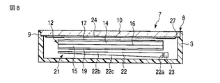
この実施例は、上記第1の実施例の携帯電話機1において、表示部保護板10と実質的に同じ大きさ及び形状に形成された2枚の反射偏光板24a,24bを備え、その一方の反射偏光板24aを、表示部保護板10の外面に貼付け、他方の反射偏光板24bを、その反射軸を、前記一方の反射偏光板24aの反射軸と実質的に平行にして前記保護板10の内面に貼付けたものであり、他の構成は第1の実施例と同じである。   This embodiment includes two reflective polarizing plates 24a and 24b formed in substantially the same size and shape as the display unit protection plate 10 in the mobile phone 1 of the first embodiment, and one of them. The reflective polarizing plate 24a is affixed to the outer surface of the display unit protective plate 10, and the other reflective polarizing plate 24b has the reflective axis substantially parallel to the reflective axis of the one reflective polarizing plate 24a. The other structure is the same as that of the first embodiment.

この実施例によれば、外部から入射した光のうちの前記反射偏光板24a,24bの反射軸と平行な方向の振動成分の光を、前記保護板10の外面に貼付けられた第1の反射偏光板24aにより鏡面反射し、さらに、前記反射軸と平行な方向の振動成分の光のうちの前記第1の反射偏光板24aで反射されずに表示部保護板10側に漏れた光を、前記保護板10の内面に貼付けられた第2の反射偏光板24bにより鏡面反射することができるため、より反射率の高いミラーを形成することができる。   According to this embodiment, the light of the vibration component in the direction parallel to the reflection axis of the reflective polarizing plates 24 a and 24 b of the light incident from the outside is attached to the outer surface of the protective plate 10. The light that is specularly reflected by the polarizing plate 24a and further leaked to the display unit protection plate 10 side without being reflected by the first reflective polarizing plate 24a out of the vibration component light in the direction parallel to the reflection axis, Since the second reflective polarizing plate 24b attached to the inner surface of the protective plate 10 can be mirror-reflected, a mirror with higher reflectivity can be formed.

(第4の実施形態)
図10はこの発明の第4の実施例を示す折りたたみ型携帯電話機の蓋部の断面図である。なお、この実施例において、上記第1の実施例に対応するものには図に同符号を付し、同一のものについてはその説明を省略する。
(Fourth embodiment)
FIG. 10 is a cross-sectional view of a lid portion of a foldable mobile phone showing a fourth embodiment of the present invention. In this embodiment, parts corresponding to those in the first embodiment are given the same reference numerals in the drawings, and description of the same parts is omitted.

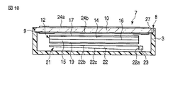
この実施例は、上記第3の実施例における2枚の反射偏光板24a,24bをそれぞれ、液晶表示パネル12の観察側の面よりも大きく、表示部保護板10よりも小さい形状に形成し、前記保護板10の内面の周縁部の内面に、上記第2の実施例と同様に遮光膜27を設けたものであり、他の構成は第の実施例と同じである。 In this embodiment, the two reflective polarizing plates 24a and 24b in the third embodiment are formed in a shape larger than the observation side surface of the liquid crystal display panel 12 and smaller than the display portion protection plate 10, The light shielding film 27 is provided on the inner surface of the peripheral edge of the inner surface of the protective plate 10 in the same manner as in the second embodiment, and the other configurations are the same as those in the third embodiment.

(第5の実施形態)
図11はこの発明の第5の実施例を示す折りたたみ型携帯電話機の蓋部の断面図である。なお、この実施例において、上記第1の実施例に対応するものには図に同符号を付し、同一のものについてはその説明を省略する。
(Fifth embodiment)
FIG. 11 is a cross-sectional view of a lid portion of a foldable mobile phone showing a fifth embodiment of the present invention. In this embodiment, parts corresponding to those in the first embodiment are given the same reference numerals in the drawings, and description of the same parts is omitted.

この実施例は、表示部7を構成する表示パネルとして、観察側とは反対側だけに偏光板19を備えた液晶表示パネル12aを備え、反射偏光板24を、その透過軸を前記液晶表示パネル12aの前記反対側の偏光板19の透過軸の向きに対して予め定めた方向に向けて配置することにより、前記液晶表示パネル12aに、前記反射偏光板24を観察側の偏光板とした表示を行わせるようにしたものであり、他の構成は第1の実施例と同じである。なお、この実施例において、前記反射偏光板24は、第1の実施例の配置に限らず、第2〜第4の実施例のいずれかと同様に配置してもよい。   This embodiment includes a liquid crystal display panel 12a provided with a polarizing plate 19 only on the side opposite to the observation side as a display panel constituting the display unit 7, and a reflective polarizing plate 24, the transmission axis of which is the liquid crystal display panel. A display in which the reflective polarizing plate 24 is used as an observation-side polarizing plate on the liquid crystal display panel 12a by disposing it in a predetermined direction with respect to the direction of the transmission axis of the polarizing plate 19 on the opposite side of 12a. The other configuration is the same as that of the first embodiment. In this embodiment, the reflective polarizing plate 24 is not limited to the arrangement of the first embodiment, and may be arranged in the same manner as any of the second to fourth embodiments.

(第6の実施形態)
図12はこの発明の第6の実施例を示す折りたたみ型携帯電話機の蓋部の断面図である。なお、この実施例において、上記第1の実施例に対応するものには図に同符号を付し、同一のものについてはその説明を省略する。
(Sixth embodiment)
FIG. 12 is a cross-sectional view of a lid portion of a foldable mobile phone showing a sixth embodiment of the present invention. In this embodiment, parts corresponding to those in the first embodiment are given the same reference numerals in the drawings, and description of the same parts is omitted.

この実施例は、表示部7を構成する表示パネルとして、自発光型の表示パネル、例えば有機EL(エレクトロルミネッセンス)表示パネル28を備え、第1の実施例における面光源21を省略したものであり、他の構成は第1の実施例と同じである。   In this embodiment, a self-luminous display panel, for example, an organic EL (electroluminescence) display panel 28 is provided as a display panel constituting the display unit 7, and the surface light source 21 in the first embodiment is omitted. Other configurations are the same as those of the first embodiment.

前記有機EL表示パネル28は、その観察側に、外部から入射した光の表面反射を軽減するための円偏光板29と偏光板(互いに直交する2つの方向に吸収軸と透過軸とをもった吸収偏光板)30とを備えており、この円偏光板29と偏光板30は、前記偏光板30を観察側の最も外面に位置させて積層されている。   The organic EL display panel 28 has, on its observation side, a circularly polarizing plate 29 and a polarizing plate (absorption axis and transmission axis in two directions orthogonal to each other) for reducing the surface reflection of light incident from the outside. The circularly polarizing plate 29 and the polarizing plate 30 are laminated with the polarizing plate 30 positioned on the outermost surface on the observation side.

そして、この実施例では、反射偏光板24を、その透過軸を、前記EL表示パネル28の観察側の最も外面に配置された前記偏光板30の透過軸と実質的に平行にして配置している。なお、この実施例において、前記反射偏光板24は、第1の実施例の配置に限らず、第2〜第4の実施例のいずれかと同様に配置してもよい。   In this embodiment, the reflective polarizing plate 24 is arranged with its transmission axis substantially parallel to the transmission axis of the polarizing plate 30 arranged on the outermost surface of the EL display panel 28 on the observation side. Yes. In this embodiment, the reflective polarizing plate 24 is not limited to the arrangement of the first embodiment, and may be arranged in the same manner as any of the second to fourth embodiments.

(他の実施形態)
なお、上記各実施例の電子機器は、折りたたみ型の携帯電話機であるが、この発明は、折りたたみ型以外の携帯電話機、電子辞書、デジタルカメラ等の、表示部を備えた電子機器に広く適用することができる。
(Other embodiments)
Although the electronic devices of the above embodiments are foldable mobile phones, the present invention is widely applied to electronic devices having a display unit, such as mobile phones other than the foldable type, electronic dictionaries, and digital cameras. be able to.

この発明の第1の実施例を示す表示部を備えた折りたたみ型携帯電話機の使用状態における正面図。BRIEF DESCRIPTION OF THE DRAWINGS The front view in the use condition of the folding-type mobile phone provided with the display part which shows 1st Example of this invention. 前記携帯電話機の図1のII−II線に沿う拡大断面図。The expanded sectional view which follows the II-II line | wire of FIG. 1 of the said mobile telephone. 前記携帯電話機の表示部を構成する液晶表示パネルと反射偏光板の斜視図。Perspective view of a liquid crystal display panel and the reflective polarizing plate constituting the display portion of the portable phone. 液晶表示パネルに黒を表示させたときの表示部の光の経路を示す光線図。The light ray figure which shows the path | route of the light of a display part when displaying black on a liquid crystal display panel. 液晶表示パネルに画像を表示させたときの表示部の光の経路を示す光線図。The light ray figure which shows the path | route of the light of a display part when an image is displayed on a liquid crystal display panel. 前記表示部の表示窓全域をミラーとしたときの正面図。The front view when the display window whole region of the said display part is made into a mirror. 前記表示部の画像を表示したときの正面図。The front view when the image of the said display part is displayed. この発明の第2の実施例を示す折りたたみ型携帯電話機の蓋部の断面図。Sectional drawing of the cover part of the foldable mobile telephone which shows 2nd Example of this invention. この発明の第3の実施例を示す折りたたみ型携帯電話機の蓋部の断面図。Sectional drawing of the cover part of the folding-type mobile telephone which shows 3rd Example of this invention. この発明の第4の実施例を示す折りたたみ型携帯電話機の蓋部の断面図。Sectional drawing of the cover part of the folding type mobile telephone which shows the 4th Example of this invention. この発明の第5の実施例を示す折りたたみ型携帯電話機の蓋部の断面図。Sectional drawing of the cover part of the foldable mobile telephone which shows 5th Example of this invention. この発明の第6の実施例を示す折りたたみ型携帯電話機の蓋部の断面図。Sectional drawing of the cover part of the folding type mobile telephone which shows the 6th Example of this invention.

符号の説明Explanation of symbols

1…折りたたみ型携帯電話機(電子機器)、2…本体ケース、3…蓋ケース、7…表示部、8…表示窓、9…開口部、10…表示部保護板、12…液晶表示パネル、13…画面エリア、14,15…基板、17…観察側偏光板、18…透過軸、19…反対側偏光板、21…面光源、24,24a,24b…反射偏光板、25…透過軸、26…反射軸、27…遮光膜、28…有機EL表示パネル、29…円偏光板、30…偏光板。   DESCRIPTION OF SYMBOLS 1 ... Folding type | mold mobile phone (electronic device), 2 ... Main body case, 3 ... Cover case, 7 ... Display part, 8 ... Display window, 9 ... Opening part, 10 ... Display part protection board, 12 ... Liquid crystal display panel, 13 ... screen area, 14, 15 ... substrate, 17 ... observation side polarizing plate, 18 ... transmission axis, 19 ... opposite side polarizing plate, 21 ... surface light source, 24, 24a, 24b ... reflection polarizing plate, 25 ... transmission axis, 26 DESCRIPTION OF SYMBOLS ... Reflection axis, 27 ... Light shielding film, 28 ... Organic EL display panel, 29 ... Circularly-polarizing plate, 30 ... Polarizing plate.

Claims (9)

所定の領域に画素が配列された表示パネルと、
前記表示パネルよりも広い面積に形成されているとともに、前記表示パネルに対向するように配置された保護板と、
前記表示パネルを収容するとともに、所定の開口部に前記保護板を嵌装する筐体と、
前記保護板に貼付けられた2枚の反射偏光板と、
を備え、
前記2枚の反射偏光板のうちの、一方の反射偏光板は、前記保護板の前記筐体の外側に向いた外面に貼付けられ、他方の反射偏光板は、前記一方の反射偏光板と対向するように前記保護板の前記筐体の内側に向いた内面に貼付けられ、
前記他方の反射偏光板の反射軸は、前記一方の反射偏光板の反射軸と実質的に平行である、
ことを特徴とする表示部を備えた電子機器。
A display panel in which pixels are arranged in a predetermined area;
A protective plate that is formed in a larger area than the display panel and is arranged to face the display panel;
A housing for housing the display panel and fitting the protective plate in a predetermined opening,
Two reflective polarizing plates affixed to the protective plate;
With
Of the two reflective polarizing plates, one reflective polarizing plate is attached to the outer surface of the protective plate facing the outside of the housing, and the other reflective polarizing plate faces the one reflective polarizing plate. Pasted on the inner surface of the protective plate facing the inside of the housing,
The reflection axis of the other reflection polarizing plate is substantially parallel to the reflection axis of the one reflection polarizing plate.
An electronic device provided with a display portion characterized by the above.
前記表示パネルと前記他方の反射偏光板との間に配置されているとともに、前記所定の領域に対応した領域に開口領域が設けられた遮光部材を備えていることを特徴とする請求項1に記載の表示部を備えた電子機器。 The light-shielding member which is arrange | positioned between the said display panel and said other reflective polarizing plate, and was provided with the opening area | region in the area | region corresponding to the said predetermined area | region is provided. An electronic device provided with the display portion described. 前記2枚の反射偏光板は、前記表示パネルよりも広い面積に形成されていることを特徴とする請求項1または2に記載の表示部を備えた電子機器。 The electronic apparatus having a display unit according to claim 1, wherein the two reflective polarizing plates are formed in a larger area than the display panel. 前記表示パネルは、少なくとも一枚の基板と、前記基板と前記他方の反射偏光板との間に配置された吸収偏光板と、を有し、
前記吸収偏光板は、該吸収偏光板の透過軸が前記2枚の反射偏光板の透過軸に対して平行になるように配置されていることを特徴とする請求項1から3の何れかに記載の表示部を備えた電子機器。
The display panel has at least one substrate, and an absorbing polarizing plate disposed between the substrate and the other reflective polarizing plate,
4. The absorbing polarizing plate is arranged so that a transmission axis of the absorbing polarizing plate is parallel to a transmission axis of the two reflective polarizing plates. An electronic device provided with the display portion described.
機器ケースと、An equipment case,
前記機器ケース内に配置された表示パネルと、A display panel disposed in the device case;
前記機器ケースの前記表示パネルの観察側の面と対向する部分に、前記表示パネルの観察側の面よりも大きい形状に形成された表示窓と、A display window formed in a shape that is larger than the observation side surface of the display panel, in a portion facing the observation side surface of the display panel of the device case,
前記表示パネルの観察側に配置され、前記表示パネルの観察側の面よりも大きい形状に形成され、且つ、互いに直交する2つの方向に透過軸と反射軸とをもち、入射光の互いに直交する2つの振動成分のうちの前記透過軸と平行な方向の振動成分の光を透過させ、前記反射軸と平行な方向の振動成分の光を反射する2枚の反射偏光板と、Arranged on the viewing side of the display panel, formed to be larger than the viewing side surface of the display panel, and having a transmission axis and a reflection axis in two directions orthogonal to each other, and the incident light is orthogonal to each other Two reflective polarizing plates that transmit light of a vibration component in a direction parallel to the transmission axis of two vibration components and reflect light of a vibration component in a direction parallel to the reflection axis;
を備え、With
前記表示窓は、前記機器ケースに形成された開口部と、前記開口部に嵌装された表示部保護板を有し、The display window has an opening formed in the device case, and a display part protection plate fitted in the opening.
前記2枚の反射偏光板のうちの、一方の反射偏光板は、前記表示部保護板の前記機器ケースの外側に向いた外面に貼付けられ、他方の反射偏光板は、前記一方の反射偏光板と対向するように前記表示部保護板の前記機器ケースの内側に向いた内面に貼付けられ、Of the two reflective polarizing plates, one reflective polarizing plate is attached to the outer surface of the display unit protection plate facing the outside of the device case, and the other reflective polarizing plate is the one reflective polarizing plate. Affixed to the inner surface of the display case protection plate facing the inner side of the device case,
前記他方の反射偏光板の反射軸は、前記一方の反射偏光板の反射軸と実質的に平行である、The reflection axis of the other reflection polarizing plate is substantially parallel to the reflection axis of the one reflection polarizing plate.
ことを特徴とする表示部を備えた電子機器。An electronic device provided with a display portion characterized by the above.
前記2枚の反射偏光板は、前記表示部保護板と実質的に同じ大きさ及び形状に形成されていることを特徴とする請求項5に記載の表示部を備えた電子機器。6. The electronic apparatus with a display unit according to claim 5, wherein the two reflective polarizing plates are formed in substantially the same size and shape as the display unit protection plate. 前記2枚の反射偏光板は、前記表示パネルの観察側の面よりも大きく、前記表示部保護板よりも小さい形状に形成されていることを特徴とする請求項5に記載の表示部を備えた電子機器。The display unit according to claim 5, wherein the two reflective polarizing plates are formed in a shape that is larger than a viewing side surface of the display panel and smaller than the display unit protection plate. Electronic equipment. 前記表示パネルは、画像の表示と、画面エリアの全体を黒にする黒表示と、を選択的に行うことを特徴とする請求項5〜7のいずれかに記載の表示部を備えた電子機器。The electronic device having a display unit according to any one of claims 5 to 7, wherein the display panel selectively performs display of an image and black display that makes the entire screen area black. . 前記表示パネルは、画像の表示と、画面エリアの全体を黒にする黒表示と、前記画面エリアの全体を白にする白表示と、を選択的に行うことを特徴とする請求項5〜7のいずれかに記載の表示部を備えた電子機器。The display panel selectively performs display of an image, black display for making the entire screen area black, and white display for making the entire screen area white. An electronic device comprising the display unit according to any one of the above.
JP2008249153A 2008-09-26 2008-09-26 Electronic device with display Expired - Fee Related JP5125945B2 (en)

Priority Applications (1)

Application Number Priority Date Filing Date Title
JP2008249153A JP5125945B2 (en) 2008-09-26 2008-09-26 Electronic device with display

Applications Claiming Priority (1)

Application Number Priority Date Filing Date Title
JP2008249153A JP5125945B2 (en) 2008-09-26 2008-09-26 Electronic device with display

Publications (3)

Publication Number Publication Date
JP2010079087A JP2010079087A (en) 2010-04-08
JP2010079087A5 JP2010079087A5 (en) 2011-03-10
JP5125945B2 true JP5125945B2 (en) 2013-01-23

Family

ID=42209581

Family Applications (1)

Application Number Title Priority Date Filing Date
JP2008249153A Expired - Fee Related JP5125945B2 (en) 2008-09-26 2008-09-26 Electronic device with display

Country Status (1)

Country Link
JP (1) JP5125945B2 (en)

Families Citing this family (13)

* Cited by examiner, † Cited by third party
Publication number Priority date Publication date Assignee Title
JP5991689B2 (en) * 2012-07-25 2016-09-14 京セラディスプレイ株式会社 Liquid crystal display element
EP3370112A1 (en) * 2013-01-16 2018-09-05 Sharp Kabushiki Kaisha Mirror display
JP2015079235A (en) 2013-09-12 2015-04-23 株式会社ジャパンディスプレイ Display device
WO2016068011A1 (en) * 2014-10-28 2016-05-06 シャープ株式会社 Mirror display
JP6457283B2 (en) * 2015-02-02 2019-01-23 日東電工株式会社 Video display mirror for vehicles
JP6457284B2 (en) * 2015-02-02 2019-01-23 日東電工株式会社 Video display mirror for vehicles
WO2017105926A1 (en) * 2015-12-17 2017-06-22 3M Innovative Properties Company Mirror including reflective backlit display
KR20230107398A (en) * 2016-04-18 2023-07-14 닛토덴코 가부시키가이샤 Liquid Crystal Display Device
JP2017194672A (en) 2016-04-18 2017-10-26 日東電工株式会社 Liquid crystal display
WO2017183499A1 (en) * 2016-04-18 2017-10-26 日東電工株式会社 Liquid crystal display device
JP7280009B2 (en) 2016-04-18 2023-05-23 日東電工株式会社 liquid crystal display
JP7280008B2 (en) * 2016-04-18 2023-05-23 日東電工株式会社 liquid crystal display
KR102633523B1 (en) * 2016-04-18 2024-02-06 닛토덴코 가부시키가이샤 Liquid Crystal Display Device

Family Cites Families (2)

* Cited by examiner, † Cited by third party
Publication number Priority date Publication date Assignee Title
JP2000196718A (en) * 1998-12-30 2000-07-14 Kenji Sato Portable electronic unit
JP2004184490A (en) * 2002-11-29 2004-07-02 Seiko Epson Corp Display device and electronic appliance equipped with the same

Also Published As

Publication number Publication date
JP2010079087A (en) 2010-04-08

Similar Documents

Publication Publication Date Title
JP5125945B2 (en) Electronic device with display
JP3972947B2 (en) Liquid crystal display device and information device equipped with the same
JP4558651B2 (en) Liquid crystal display device and information equipment
CN102681232B (en) Semi-transmissive liquid crystal display device and portable terminal device
US7643107B2 (en) Liquid crystal display apparatus
JP4572888B2 (en) Liquid crystal device and electronic device
JP4607158B2 (en) Liquid crystal display device and electronic device
JP2007093849A (en) Liquid crystal device and electronic equipment
WO2004036300A1 (en) Display device and display device mounting device
JP2004069926A (en) Display device with mirror function, and electronic device
JP2002357825A (en) Liquid crystal display device and electronic device provided with the liquid crystal display device
JP2006277739A (en) Electrooptical device and electronic apparatus
JP2007127724A (en) Liquid crystal display device
US9977298B2 (en) Display panel and display apparatus having the same
JP2011013511A (en) Electronic member with protective plate
JP2009075421A (en) Liquid crystal device and electronic equipment
JP4239708B2 (en) Liquid crystal display
JP4678016B2 (en) Liquid crystal device and electronic device
JP5388037B2 (en) Liquid crystal device and electronic device
JP4466186B2 (en) Display device and electronic device
JP4837796B2 (en) Transflective liquid crystal display device and portable terminal device
JP2008070734A (en) Liquid crystal display and electronic equipment
KR20070076652A (en) Reversible liquid crystal display and handy terminal having the same
KR101692076B1 (en) Liquid Crystal Display Device
JP2006058704A (en) Liquid crystal display

Legal Events

Date Code Title Description
A521 Written amendment

Free format text: JAPANESE INTERMEDIATE CODE: A523

Effective date: 20110124

A621 Written request for application examination

Free format text: JAPANESE INTERMEDIATE CODE: A621

Effective date: 20110124

A131 Notification of reasons for refusal

Free format text: JAPANESE INTERMEDIATE CODE: A131

Effective date: 20120605

A521 Written amendment

Free format text: JAPANESE INTERMEDIATE CODE: A523

Effective date: 20120806

TRDD Decision of grant or rejection written
A01 Written decision to grant a patent or to grant a registration (utility model)

Free format text: JAPANESE INTERMEDIATE CODE: A01

Effective date: 20121002

A01 Written decision to grant a patent or to grant a registration (utility model)

Free format text: JAPANESE INTERMEDIATE CODE: A01

A61 First payment of annual fees (during grant procedure)

Free format text: JAPANESE INTERMEDIATE CODE: A61

Effective date: 20121015

R150 Certificate of patent (=grant) or registration of utility model

Free format text: JAPANESE INTERMEDIATE CODE: R150

FPAY Renewal fee payment (prs date is renewal date of database)

Free format text: PAYMENT UNTIL: 20151109

Year of fee payment: 3

LAPS Cancellation because of no payment of annual fees