JP5125375B2 - Seat belt through anchor, seat belt device and vehicle - Google Patents
Seat belt through anchor, seat belt device and vehicle Download PDFInfo
- Publication number
- JP5125375B2 JP5125375B2 JP2007258856A JP2007258856A JP5125375B2 JP 5125375 B2 JP5125375 B2 JP 5125375B2 JP 2007258856 A JP2007258856 A JP 2007258856A JP 2007258856 A JP2007258856 A JP 2007258856A JP 5125375 B2 JP5125375 B2 JP 5125375B2
- Authority
- JP
- Japan
- Prior art keywords
- shaft
- seat belt
- anchor
- cylindrical body
- vehicle
- Prior art date
- Legal status (The legal status is an assumption and is not a legal conclusion. Google has not performed a legal analysis and makes no representation as to the accuracy of the status listed.)
- Expired - Fee Related
Links
Images


Classifications
-
- B—PERFORMING OPERATIONS; TRANSPORTING
- B60—VEHICLES IN GENERAL
- B60R—VEHICLES, VEHICLE FITTINGS, OR VEHICLE PARTS, NOT OTHERWISE PROVIDED FOR
- B60R22/00—Safety belts or body harnesses in vehicles
- B60R22/18—Anchoring devices
- B60R22/185—Anchoring devices with stopping means for acting directly upon the belt in an emergency, e.g. by clamping or friction
- B60R22/1855—Anchoring devices with stopping means for acting directly upon the belt in an emergency, e.g. by clamping or friction the means being sensitive to belt tension
-
- B—PERFORMING OPERATIONS; TRANSPORTING
- B60—VEHICLES IN GENERAL
- B60R—VEHICLES, VEHICLE FITTINGS, OR VEHICLE PARTS, NOT OTHERWISE PROVIDED FOR
- B60R22/00—Safety belts or body harnesses in vehicles
- B60R22/18—Anchoring devices
- B60R2022/1818—Belt guides
- B60R2022/1825—Belt guides using rollers
-
- B—PERFORMING OPERATIONS; TRANSPORTING
- B60—VEHICLES IN GENERAL
- B60R—VEHICLES, VEHICLE FITTINGS, OR VEHICLE PARTS, NOT OTHERWISE PROVIDED FOR
- B60R22/00—Safety belts or body harnesses in vehicles
- B60R22/18—Anchoring devices
- B60R22/24—Anchoring devices secured to the side, door, or roof of the vehicle
Description
本発明は、シートベルトが掛通されるスルーアンカに係り、特に、シートベルトが掛けられる掛軸が回転可能となっており、シートベルトから該掛軸に対し所定以上の押圧力が加えられた場合に該掛軸の回転を阻止するストッパ機構が設けられたシートベルトのスルーアンカに関する。また、本発明は、このシートベルトのスルーアンカを備えたシートベルト装置及び車両に関する。 The present invention relates to a through anchor through which a seat belt is passed, and in particular, when a hanging shaft on which a seat belt is hung is rotatable and a pressing force of a predetermined level or more is applied from the seat belt to the hanging shaft. The present invention relates to a through anchor for a seat belt provided with a stopper mechanism for preventing rotation of the hanging shaft. The present invention also relates to a seat belt apparatus and a vehicle provided with a through anchor for the seat belt.
シートベルト装置にあっては、リトラクタから引き出されたシートベルトがスルーアンカに掛通され、乗員の前面側に引き回される。このリトラクタは、シートベルトを巻き取り方向に引張るバネを備えており、シートベルトには常に該巻き取り方向の張力が加えられている。 In the seat belt device, the seat belt pulled out from the retractor is passed through the through anchor and drawn around the front side of the occupant. The retractor includes a spring that pulls the seat belt in the winding direction, and a tension in the winding direction is always applied to the seat belt.
シートベルトを引き出す場合、シートベルトをリトラクタに巻き取る場合のいずれにも、シートベルトにはスルーアンカの摩擦力が加えられる。この摩擦力を低下させてシートベルトをスムーズに引き出し及び巻き取りしうるようにするために、スルーアンカに回転自在な掛軸を設け、この掛軸にシートベルトを掛ける構造が知られている。 When pulling out the seat belt or winding the seat belt around the retractor, the friction force of the through anchor is applied to the seat belt. In order to reduce the frictional force so that the seat belt can be smoothly pulled out and taken up, a structure is provided in which a through shaft is provided on the through anchor and the seat belt is hung on the shaft.
ところで、リトラクタにEA機構を組み込むことがある。該リトラクタは、自動車の衝突時等の緊急時にシートベルトの引き出しをロックして乗員を座席に拘束する。EA機構は、シートベルトの引き出しがロックされた後、シートベルトに対し乗員から荷重が加えられたときに徐々にシートベルトをリトラクタから送り出し、乗員に加えられる衝撃を吸収するためのものである。 By the way, an EA mechanism may be incorporated in the retractor. The retractor locks the seat belt drawer and restrains the occupant to the seat in an emergency such as a car collision. The EA mechanism is for absorbing the impact applied to the occupant by gradually feeding the seat belt from the retractor when a load is applied to the seat belt from the occupant after the seat belt drawer is locked.
上記のようにスルーアンカの掛軸が回転可能であると、シートベルトの引き出しがロックされた後にシートベルトに乗員の荷重が加えられた場合、この荷重がスルーアンカの摩擦力を殆ど受けずにほぼそのままEA機構に加えられることになり、EA機構として大きな荷重を負担しうるものを用いる必要が生じ、EA機構のコストあるいは重量が増大する。 As described above, when the hanging shaft of the through anchor is rotatable, when a passenger's load is applied to the seat belt after the seat belt drawer is locked, the load hardly receives the frictional force of the through anchor. It will be added to the EA mechanism as it is, and it will be necessary to use an EA mechanism that can bear a large load, increasing the cost or weight of the EA mechanism.
米国特許第4993746号には、シートベルトから掛軸に対し所定以上の押圧力が加えられた場合に該掛軸の回転を阻止するストッパ機構を備えたシートベルトのスルーアンカが記載されている。 U.S. Pat. No. 4,993,746 describes a through anchor for a seat belt provided with a stopper mechanism that prevents rotation of the hanging shaft when a predetermined pressing force is applied from the seat belt to the hanging shaft.
同号では、該掛軸は、アンカベース(clevis)に回転不能に両端が支持されたシャフト(spindle)と、該シャフトに回転可能に外嵌した筒体(roller)とを備えている。該筒体の内径はシャフトの外径よりも大となっている。該シャフトの外周面からは、凸部(tooth)が突設されている。また、筒体の内周面には、該筒体の周方向に間隔をおいて、該筒体の軸心線方向に延在する複数の凸条(teeth)が設けられており、これらの凸条同士の間が、シャフトの凸部が係合可能な凹部となっている。 In the same reference, the hanging shaft includes a shaft that is supported at both ends by an anchor base (clevis) so as not to rotate, and a cylinder that is rotatably fitted on the shaft. The inner diameter of the cylindrical body is larger than the outer diameter of the shaft. From the outer peripheral surface of the shaft, a protrusion is formed. A plurality of protrusions (teeth) extending in the axial direction of the cylinder are provided on the inner peripheral surface of the cylinder at intervals in the circumferential direction of the cylinder. Between the ridges, a recess is engageable with the projection of the shaft.
同号では、筒体の軸心線方向の両端側の周縁部がそれぞれ弾性変形可能部(spring extension)となっている。この弾性変形可能部は、ネオプレン等の柔軟な材質よりなる。 In the same number, the peripheral edge portions on both end sides in the axial direction of the cylindrical body are respectively elastically deformable portions (spring extension). This elastically deformable portion is made of a flexible material such as neoprene.
この筒体の軸心線方向の両端面にそれぞれ環形のエンドキャップ(end cap)が取り付けられ、このエンドキャップの中央孔にシャフトが挿通されている。筒体は、このエンドキャップを介して、該凸部と凹部とが離隔するようにシャフトに支持されている。 Ring-shaped end caps (end caps) are respectively attached to both end surfaces of the cylindrical body in the axial center line direction, and a shaft is inserted into a central hole of the end cap. The cylindrical body is supported by the shaft through the end cap so that the convex portion and the concave portion are separated from each other.
この筒体に掛けられたシートベルトから該筒体に加えられる押圧力が所定値よりも小さい場合には、筒体の両端側の弾性変形可能部は変形しない。このとき、筒体の内周面の凹部とシャフトの外周面の凸部とが離隔しているので、筒体は回転自在となっている。 When the pressing force applied to the cylinder from the seat belt hung on the cylinder is smaller than a predetermined value, the elastically deformable portions on both ends of the cylinder are not deformed. At this time, since the concave portion on the inner peripheral surface of the cylindrical body and the convex portion on the outer peripheral surface of the shaft are separated from each other, the cylindrical body is rotatable.
シートベルトから筒体に加えられる押圧力が所定値以上になると、筒体の両端側の弾性変形可能部がそれぞれ座屈する如く変形し、これにより、筒体がシャフトに接近して該凹部と凸部とが係合し、筒体が回転不能となる。この結果、該筒体からシートベルトに対し摩擦力が加えられるようになる。
上記米国特許第4993746号のスルーアンカにあっては、筒体の軸心線方向の両端側が弾性変形可能部となっているが、この弾性変形可能部は筒体の外面の一部を構成しているため、この筒体に掛けられたシートベルトが該弾性変形可能部と擦れ合う。そのため、この弾性変形可能部には、所期の変形特性と共に、高い耐久性が要求される。このような弾性変形可能部を有する筒体を備えたスルーアンカは、高コストである。 In the through anchor of the above-mentioned U.S. Pat. No. 4,993,746, both end sides in the axial direction of the cylindrical body are elastically deformable portions, but these elastically deformable portions constitute a part of the outer surface of the cylindrical body. Therefore, the seat belt hung on the cylindrical body rubs against the elastically deformable portion. Therefore, this elastically deformable portion is required to have high durability as well as desired deformation characteristics. A through anchor provided with a cylindrical body having such an elastically deformable portion is expensive.
本発明は、アンカベースに回転不能に両端が支持されたシャフトと、該シャフトに回転可能に外嵌した筒体とによりシートベルトの掛軸が構成されていると共に、シートベルトから該筒体に所定以上の押圧力が加えられた場合に該筒体の回転を阻止するストッパ機構が設けられたシートベルトのスルーアンカにおいて、該筒体の耐久性が良好であり、且つ低コストにて構成可能なシートベルトのスルーアンカを提供することを目的とする。 According to the present invention, a seat belt hanging shaft is constituted by a shaft that is supported at both ends by an anchor base so as not to rotate, and a cylindrical body that is rotatably fitted to the shaft, and the seat belt is provided with a predetermined shaft. In the through anchor of the seat belt provided with a stopper mechanism for preventing the rotation of the cylindrical body when the above pressing force is applied, the cylindrical body has good durability and can be configured at low cost. An object is to provide a through anchor for a seat belt.
請求項1のシートベルトのスルーアンカは、リトラクタから引き出されたシートベルトが掛けられる掛軸と、該掛軸の両端を支持するアンカベースとを有するシートベルトのスルーアンカであって、該掛軸は、該アンカベースに回転不能に両端が支持されたシャフトと、該シャフトに回転可能に外嵌した筒体とを備えており、シートベルトから該筒体に対し所定以上の押圧力が加えられた場合に該筒体の回転を阻止するストッパ機構が設けられたシートベルトのスルーアンカにおいて、該ストッパ機構は、該シャフトの外周面及び筒体の内周面の一方に設けられた凸部と、他方に設けられた、該凸部が係合可能な凹部と、該筒体とシャフトとの間に配置されており、シートベルトから該筒体に対する押圧力が所定値よりも小さい場合には該凹部と凸部とが離隔するように該筒体を付勢するバネとを備え、シートベルトから該筒体に対し該所定値以上の押圧力が加えられた場合には、該筒体が該シャフトに接近して該凸部と凹部とが係合し、これにより該筒体の回転が阻止されるシートベルトのスルーアンカであって、該筒体の軸心線方向の両端側にそれぞれベアリングが回転可能に内嵌しており、各ベアリングは、該シャフトに対し回転不能に且つ該筒体の該シャフトに対する接近及び離反方向に摺動可能に保持されており、各ベアリングが該筒体の該シャフトに対する接近方向に摺動することにより、該筒体が該シャフトに接近して前記凸部と凹部とが係合するように構成されており、前記バネは、各ベアリングを、該筒体の該シャフトに対する離反方向に付勢していることを特徴とするものである。
請求項2のシートベルトのスルーアンカは、請求項1において、前記シャフトは、その長手方向と交叉方向の断面形状が略長方形の角棒状のものであり、該シャフトの長手方向の両端側が前記アンカベースに回転不能に支持されており、該シャフトの外面のうち、該シャフトの該断面の長辺方向に延在する1対の側面は、前記筒体の該シャフトに対する接近及び離反方向に延在した、該筒体の移動を案内するガイド面となっており、該筒体は、内径が該シャフトの該断面の対角線方向の幅よりも大きなものとなっており、前記ベアリングに、それぞれ、該シャフトが挿通されたシャフト挿通孔が設けられており、各シャフト挿通孔は、略長方形の開口形状を有したものとなっており、各シャフト挿通孔の短辺方向の幅は、該シャフトの該断面の短辺方向の幅と同等か、又は、該シャフトの該断面の短辺方向の幅よりも大きく且つ該シャフトの該断面の長辺方向の幅よりも小さなものとなっており、各シャフト挿通孔の長辺方向の幅は、該シャフトの該断面の長辺方向の幅よりも所定幅大きなものとなっており、各シャフト挿通孔に対し、該シャフトは、その断面の長辺方向を各シャフト挿通孔の長辺方向として挿通されており、これにより、各ベアリングは、該シャフトに対し回転不能に保持されると共に、該シャフトの前記ガイド面に沿って摺動可能となっており、各シャフト挿通孔は、該シャフト挿通孔の長辺方向の一端側の縁部に該シャフトが当接した状態において、該筒体が各ベアリングによって該シャフトに対し略同軸状に支持されるように配置されており、前記バネは、各ベアリングを、該シャフト挿通孔の長辺方向の他端側に付勢していることを特徴とするものである。
The through anchor of the seat belt according to claim 1 is a through anchor of the seat belt having a hanging shaft on which the seat belt pulled out from the retractor is hung, and an anchor base that supports both ends of the hanging shaft. A shaft having both ends supported non-rotatably on the anchor base and a cylindrical body that is externally fitted to the shaft are provided. When a predetermined pressing force is applied to the cylindrical body from a seat belt In the through anchor of the seat belt provided with a stopper mechanism for preventing the rotation of the cylindrical body, the stopper mechanism includes a convex portion provided on one of the outer peripheral surface of the shaft and the inner peripheral surface of the cylindrical body, and the other. The provided concave portion is engageable with the convex portion and is disposed between the cylindrical body and the shaft. When the pressing force from the seat belt to the cylindrical body is smaller than a predetermined value, the concave portion is provided. And a spring for urging the cylindrical body so that the convex portion is separated from the convex portion, and when a pressing force greater than the predetermined value is applied to the cylindrical body from a seat belt, the cylindrical body is the shaft Is a through anchor of the seat belt in which the convex portion and the concave portion are engaged with each other to prevent rotation of the cylindrical body, and bearings are respectively provided at both end sides in the axial direction of the cylindrical body. The bearings are rotatably fitted, and the bearings are held so as to be non-rotatable with respect to the shaft and to be slidable in the approaching and separating directions of the cylindrical body. By sliding in the approaching direction with respect to the shaft, the cylindrical body is configured to approach the shaft so that the convex portion and the concave portion engage with each other, and the spring is configured so that each bearing is connected to the cylindrical body. JP that biases the separating direction with respect to the shaft It is an.
According to a second aspect of the present invention, there is provided a through anchor for a seat belt according to the first aspect, wherein the shaft has a rectangular bar shape whose cross section in the longitudinal direction and the cross direction is substantially rectangular, and both end sides in the longitudinal direction of the shaft are the anchors. A pair of side surfaces that are supported by the base in a non-rotatable manner and extend in the long side direction of the cross section of the shaft of the outer surface of the shaft extend in the approaching and separating directions of the cylindrical body with respect to the shaft The cylindrical body has a guide surface that guides the movement of the cylindrical body, and the cylindrical body has an inner diameter that is larger than the width in the diagonal direction of the cross section of the shaft. A shaft insertion hole into which the shaft is inserted is provided, each shaft insertion hole has a substantially rectangular opening shape, and the width in the short side direction of each shaft insertion hole is the width of the shaft. cross section Each shaft insertion hole is equal to the width in the short side direction, or larger than the width in the short side direction of the cross section of the shaft and smaller than the width in the long side direction of the cross section of the shaft. The width in the long side direction of the shaft is larger by a predetermined width than the width in the long side direction of the cross section of the shaft. It is inserted as the long side direction of the insertion hole, whereby each bearing is held non-rotatable with respect to the shaft and is slidable along the guide surface of the shaft. The insertion hole is arranged so that the cylindrical body is supported substantially coaxially with respect to the shaft by each bearing in a state where the shaft is in contact with an edge portion on one end side in the long side direction of the shaft insertion hole. And the spring is Each bearing is characterized in that it is biased to the other end in the long side direction of the shaft insertion hole.
請求項3のシートベルトのスルーアンカは、請求項1又は2において、該バネは、前記掛軸の軸心線と平行方向に延在した板バネであることを特徴とするものである。 According to a third aspect of the present invention, the through anchor of the seat belt according to the first or second aspect is characterized in that the spring is a leaf spring extending in a direction parallel to the axial line of the hanging shaft.
請求項4のシートベルトのスルーアンカは、請求項1ないし3のいずれか1項において、前記シャフトは、前記筒体の移動を案内するガイド面を備えており、該筒体は、該ガイド面に沿って該シャフトに対し接近及び離隔方向に移動可能となっており、該ガイド面は、前記シートベルトが座席着座者に装着された状態における、該シートベルトの該筒体よりも前記リトラクタ側の部分の延在方向L1と、該シートベルトの該筒体よりも座席着座者側の部分の延在方向L2との交叉角θの二等分線L3と略平行方向に延在していることを特徴とするものである。 The through anchor of the seat belt according to claim 4 is any one of claims 1 to 3 , wherein the shaft includes a guide surface for guiding the movement of the cylindrical body, and the cylindrical body includes the guide surface. The guide surface is movable toward and away from the shaft along the shaft, and the guide surface is closer to the retractor than the cylindrical body of the seat belt when the seat belt is worn by a seat occupant. the extending direction L 1 of the portion of the substantially extends in a direction parallel to the bisector L 3 crossover angle θ of the extending direction L 2 of the portions of the seat occupant side of the tube body of the seat belt It is characterized by that.
請求項5のシートベルト装置は、座席着座者の身体に沿って引き回されるシートベルトと、該シートベルトが掛通された、請求項1ないし4のいずれか1項に記載のシートベルトのスルーアンカと、該シートベルトの後端側が巻き取り及び引き出し可能に接続されたリトラクタとを備えたものである。
Seat belt apparatus according to
請求項6の車両は、請求項5のシートベルト装置が設けられたものである。
The vehicle according to
請求項7の車両は、請求項6において、前記スルーアンカは、車両の座席後方部材に対し、前記シャフトの延在方向を略車両幅方向として設置されていることを特徴とするものである。 A vehicle according to a seventh aspect is characterized in that, in the sixth aspect , the through anchor is installed with respect to a seat rear member of the vehicle with the extending direction of the shaft as a substantially vehicle width direction.
請求項8の車両は、請求項6において、前記スルーアンカは、車両のピラー部に対し、前記シャフトの延在方向を略車両前後方向として設置されていることを特徴とするものである。 A vehicle according to an eighth aspect is the vehicle according to the sixth aspect , wherein the through anchor is installed with respect to a pillar portion of the vehicle so that the extending direction of the shaft is substantially the vehicle front-rear direction.
本発明(請求項1)のシートベルトのスルーアンカ、並びにこのスルーアンカを備えた本発明(請求項5,6)のシートベルト装置及び車両にあっては、該スルーアンカの筒体とシャフトとの間にバネを設け、このバネにより、筒体の内周面及びシャフトの外周面にそれぞれ設けられた凸部と凹部とが離隔するように、該筒体を付勢している。そのため、この筒体の全体を硬質な材質により構成することができるため、筒体の耐久性を良好なものとすることができる。また、このような筒体としては、安価な合成樹脂等により構成された、ごく一般的な従来品と同等のものを用いることができるので、比較的低コストにてスルーアンカを構成することが可能である。
The through anchor of the seat belt of the present invention (Claim 1), and the seat belt apparatus and vehicle of the present invention (
本発明においては、請求項3の通り、この筒体を付勢するバネとしては、板バネが好適である。この板バネは安価である。また、この板バネを掛軸の軸心線と平行方向に延在させて配置することにより、バネ設置スペースの省スペース化を図ることができる。 In the present invention, as described in claim 3 , a leaf spring is suitable as the spring for urging the cylindrical body. This leaf spring is inexpensive. Further, by arranging this leaf spring so as to extend in a direction parallel to the axial center line of the hanging shaft, the space for installing the spring can be saved.
請求項4の態様においては、シャフトに、筒体の移動を案内するガイド面が設けられており、且つこのガイド面は、シートベルトが座席着座者に装着された状態における、該シートベルトの該筒体よりも前記リトラクタ側の部分の延在方向L1と、該シートベルトの該筒体よりも座席着座者側の部分の延在方向L2との交叉角の二等分線L3と略平行方向に延在している。本態様にあっては、シートベルトが座席着座者に装着された状態において該シートベルトから筒体に所定以上の押圧力が加えられた場合には、この押圧力の方向とガイド面の延在方向とが略平行方向となるので、筒体がこのガイド面に案内されてシャフトに接近する。これにより、筒体がスムーズにロック動作する。 In the aspect of claim 4 , the shaft is provided with a guide surface for guiding the movement of the cylindrical body, and the guide surface of the seat belt in a state where the seat belt is mounted on the seat occupant. the extending direction L 1 of the retractor-side portion than the cylindrical body, the bisector L 3 crossover angle between the extension direction L 2 of the portions of the seat occupant side of the tube body of the seat belt It extends in a substantially parallel direction. In this aspect, when a predetermined pressing force is applied from the seat belt to the cylinder while the seat belt is worn by the seat occupant, the direction of the pressing force and the extension of the guide surface Since the direction is substantially parallel, the cylindrical body is guided by the guide surface and approaches the shaft. Thereby, the cylinder is smoothly locked.
また、シートベルトが座席着座者に装着されていない状態において該シートベルトから筒体に押圧力が加えられた場合、即ちシートベルトを装着しようとして該シートベルトを引き出したときや、シートベルトの装着を解除して該シートベルトを巻き取らせるときには、この押圧力の方向とガイド面の延在方向とが交叉方向となるため、筒体がシャフトに接近しにくい。これにより、シートベルトの引き出し時及び巻き取り時に筒体がロックされることが防止ないし抑制され、このシートベルトの引き出し及び巻き取りをスムーズに行うことができる。 Also, when a pressing force is applied from the seat belt to the cylinder in a state where the seat belt is not worn by the seat occupant, that is, when the seat belt is pulled out to wear the seat belt, or when the seat belt is worn When the seat belt is taken up by releasing the pressure, the direction of the pressing force and the extending direction of the guide surface are crossing directions, so that the cylindrical body is difficult to approach the shaft. As a result, the cylinder is prevented or suppressed from being locked when the seat belt is pulled out and taken up, and the seat belt can be pulled out and taken up smoothly.
本発明においては、スルーアンカは、請求項7のように、車両の座席後方部材に対し、シャフトの延在方向を略車両幅方向として設置されてもよく、請求項8のように、車両のピラー部に対し、シャフトの延在方向を略車両前後方向として設置されてもよい。
In the present invention, the through anchor, like the seventh aspect, with respect to the seat back component of the vehicle, may be installed extending direction of the shaft a substantially vehicle width direction, as claimed in
以下に、図面を参照して本発明の実施の形態について説明する。 Embodiments of the present invention will be described below with reference to the drawings.
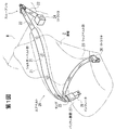
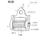
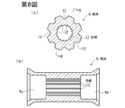
第1図は実施の形態に係るスルーアンカを備えたシートベルト装置の一例を示す斜視図、第2図はこのスルーアンカの斜視図、第3図はこのスルーアンカの分解斜視図、第4図はこのスルーアンカのアンカベースの側面図、第5図はシートベルトとしてのエアベルトのスルーアンカ付近及び該スルーアンカの側面図、第6図(a)はこのスルーアンカに用いられる板バネの側面図、第6図(b)はこの板バネの上面図、第7図(a)はこのスルーアンカに用いられるベアリングの側面図、第7図(b)はこのベアリングの端面図(第7図(a)のB−B線矢視図)、第8図(a)はこのスルーアンカの掛軸を構成する筒体の断面図(第3図のVIIIA−VIIIA線断面図)、第8図(b)は第8図(a)のB−B線断面図、第9図(a)はこのスルーアンカの非ロック時の縦断面図、第9図(b)は第9図(a)のB−B線断面図、第10図(a)はこのスルーアンカのロック時の縦断面図、第10図(b)は第10図(a)のB−B線断面図、第11図はエアベルトと筒体との係合状態を示す、第8図(a)と同様部分の断面図である。 FIG. 1 is a perspective view showing an example of a seat belt apparatus provided with a through anchor according to the embodiment, FIG. 2 is a perspective view of the through anchor, FIG. 3 is an exploded perspective view of the through anchor, and FIG. Is a side view of an anchor base of the through anchor, FIG. 5 is a side view of the vicinity of the through anchor of the air belt as a seat belt and a side view of the through anchor, and FIG. 6A is a side view of a leaf spring used in the through anchor. 6 (b) is a top view of the leaf spring, FIG. 7 (a) is a side view of a bearing used in the through anchor, and FIG. 7 (b) is an end view of the bearing (FIG. 7 ( FIG. 8 (a) is a cross-sectional view of the cylindrical body constituting the hanging shaft of the through anchor (cross-sectional view taken along the line VIIIA-VIIIA in FIG. 3), FIG. 8 (b). ) Is a cross-sectional view taken along line BB in FIG. 8 (a), and FIG. FIG. 9 (b) is a cross-sectional view taken along the line BB of FIG. 9 (a), and FIG. 10 (a) is a vertical cross-sectional view when the through anchor is locked. FIG. 10 (b) is a cross-sectional view taken along the line BB of FIG. 10 (a), and FIG. 11 is a cross-sectional view of the same portion as FIG. 8 (a), showing the engaged state of the air belt and the cylindrical body. .
なお、第2,3図及び第9,10図では、スルーアンカは、該スルーアンカの車両設置時における略車両前後方向を図の上下方向として図示されている。 In FIGS. 2 and 3 and FIGS. 9 and 10, the through anchor is shown with the substantially longitudinal direction of the through anchor when the through anchor is installed in the vehicle as the vertical direction in the figure.
この実施の形態では、スルーアンカ1は、車内に運転席と助手席とが設けられ、後席が設けられていない、所謂ツーシータータイプの車両に設置されている。ただし、本発明は、特定の車両形態に限定されない。 In this embodiment, the through anchor 1 is installed in a so-called two-seater type vehicle in which a driver's seat and a passenger seat are provided in the vehicle and no rear seat is provided. However, the present invention is not limited to a specific vehicle form.
スルーアンカ1は、シートベルトが掛けられる掛軸2と、該掛軸2を支持するアンカベース3等を有している。この掛軸2は、アンカベース3に設けられた1対のシャフト受部4,4間に回転不能に架設されたシャフト5と、このシャフト5に回転可能に外嵌した筒体6とからなる。
The through anchor 1 includes a hanging shaft 2 on which a seat belt is hung, an anchor base 3 that supports the hanging shaft 2 and the like. The hanging shaft 2 includes a
第1図に示すように、このスルーアンカ1は、該シャフト5の延在方向を略車両幅方向(即ち略左右方向)として、車体の座席後方部材Mに設置されている。該アンカベース3は、シャフト受部4,4側を車両前方とし、これと反対側を車両後方として配置されている。このアンカベース3の該シャフト受部4,4と反対側にはボルト挿通孔7が設けられており、スルーアンカ1は、このボルト挿通孔7を介してアンカボルトBにより座席後方部材Mに対し略車両幅方向に回動可能に連結されている。符号3aは、該アンカベース3の回動角度を規制する爪を示している。
As shown in FIG. 1, the through anchor 1 is installed on the seat rear member M of the vehicle body with the extending direction of the
この実施の形態では、スルーアンカ1よりも車両前方側にリトラクタ24が設置されている。このリトラクタは、第5図の通り、スルーアンカ1よりも低い位置に配置されている。このリトラクタ24からシートベルトとしてのエアベルト20が引き出されている。このエアベルト20は、リトラクタ24から車両後方へ引き出され、次いで筒体6の下側から該筒体6の車両後方側を通って該筒体6の上側へ回り込むように該筒体6に掛けられ、その後、該筒体6から車両前方側に引き回されている。
In this embodiment, the
なお、第5図においては、このエアベルト20は、座席Z(第1図)に座った乗員(図示略)の前面側に引き回され、後述のバックル装置27にラッチされた装着完了状態にて図示されている。第5図の一点鎖線L1は、この装着完了状態における、該エアベルト20の筒体6よりもリトラクタ24側の部分の延在方向を示し、一点鎖線L2は、この装着完了状態における、該エアベルト20の筒体6よりも乗員側の部分の延在方向を示し、一点鎖線L3は、これらの延在方向L1,L2同士の交叉角θの二等分線を示している。第5図の通り、この二等分線L3は、略車両前後方向であって、且つ車両前方側に向って若干下り勾配となる方向に延在している。
In FIG. 5, the
該シャフト5は、この実施の形態では、その長手方向と交叉方向の断面形状が略長方形の角棒状のものである。以下、シャフト5の断面とは、この長手方向と交叉方向の断面をいう。この実施の形態では、シャフト5の外面のうち、この断面の長辺方向に延在する1対の側面が、筒体6の移動を案内するガイド面5aとなっている。
In this embodiment, the
なお、この実施の形態では、第3図のように、シャフト5は、初めから所定厚みにて形成されたワンピース構造のものであるが、本発明においては、厚みの小さい帯板状の平シャフトを複数枚重ね合わせて角棒状のシャフト5を構成してもよい。
In this embodiment, as shown in FIG. 3, the
シャフト受部4,4は、略車両幅方向に所定距離離隔して配置されており、各シャフト受部4には、それらを略車両幅方向に貫通するシャフト挿通孔8が設けられている。第4図に示すように、このシャフト挿通孔8は略長方形の開口形状を有している。このシャフト挿通孔8の短辺方向の幅は、シャフト5の断面の短辺方向の幅と同等かそれよりも若干大きなものとなっている。また、このシャフト挿通孔8の長辺方向の幅は、シャフト5の断面の長辺方向の幅と後述の板バネ11の係止部11bの厚みとの合計と同等かそれよりも若干大きなものとなっている。
The shaft receiving portions 4 and 4 are arranged at a predetermined distance in the substantially vehicle width direction, and each shaft receiving portion 4 is provided with a
第5図の通り、各シャフト挿通孔8は、該長辺が前記二等分線L3と略平行方向に延在するように形成されている。 As Figure 5, the shaft insertion holes 8 is formed so long side extends in a direction substantially parallel to the bisector L 3.
シャフト5は、その断面の長辺方向を各シャフト挿通孔8の長辺方向として各シャフト挿通孔8に挿通され、その長手方向の両端側がそれぞれ各シャフト挿通孔8内に回転不能に保持されている。即ち、このシャフト5のガイド面5aは、第5図の通り、エアベルト20が座席乗員に装着された状態における、該エアベルト20の筒体6よりもリトラクタ24側の部分の延在方向L1と、該エアベルト20の筒体6よりも乗員側の部分の延在方向L2との交叉角θの二等分線L3と略平行方向に延在している。
The
本発明においては、これらの延在方向L1,L2と該二等分線L3との交叉角(θ/2)は、それぞれ、16〜28°程度、特に20°程度であることが好ましい。 In the present invention, the crossing angles (θ / 2) between the extending directions L 1 and L 2 and the bisector L 3 are each about 16 to 28 °, particularly about 20 °. preferable.
なお、該シャフト5の長手方向の両端側の略車両前方を向いた面(以下、前面ということがある。)には、それぞれ凹部5bが形成されており、これらの凹部5bに各シャフト挿通孔8の略車両前方側の縁部が係合することにより、シャフト5が位置決め(各シャフト挿通孔8から抜け止め)されている。
In addition,
第9図(b)に示すように、筒体6は、内径がシャフト5の断面の対角線方向の幅よりも大きなものとなっている。この筒体6の内周面には、シャフト5の略車両後方を向いた面(以下、後面ということがある。)と各ガイド面5aとが交わる凸角部5t(第9図(b))が係合可能な凹部12が形成されている。この凹部12は、筒体6の軸心線方向に延在する溝状のものであり、該筒体6の周方向に等間隔にて複数条設けられている。
As shown in FIG. 9 (b), the
この実施の形態では、該筒体6の軸心線方向の両端側にそれぞれベアリング9が設けられている。この実施の形態では、該筒体6の軸心線方向両端側がそれぞれ中間側よりも内径の大きい大径部6aとなっており、これらの大径部6aにそれぞれベアリング9が回転可能に内嵌している。
In this embodiment,
第7図の通り、各ベアリング9のシャフト挿通孔10も、略長方形の開口形状を有している。このシャフト挿通孔10も、短辺方向の幅はシャフト5の断面の短辺方向の幅と同等かそれよりも若干大きく、長辺方向の幅は、シャフト5の断面の長辺方向の幅よりも所定幅大きなものとなっている。このシャフト挿通孔10に対し、シャフト5がその断面の長辺方向を各シャフト挿通孔10の長辺方向として挿通されている。
As shown in FIG. 7, the
これにより、各ベアリング9は、シャフト5に対し回転不能に保持されると共に、該シャフト5のガイド面5aに沿って前記二等分線L3と略平行方向に摺動可能となっている。
Thus, each
これらのベアリング9により、筒体6はシャフト5に対し回転可能に、且つ該ガイド面2aに沿って前記二等分線L3と略平行方向に移動可能に支持されている。
These
なお、第9図(a),(b)の通り、各シャフト挿通孔10は、該シャフト挿通孔10の略車両前方側の縁部(以下、前縁ということがある。)にシャフト5の前面が当接した状態、即ち各ベアリング9が略車両後方への移動限に位置している状態において、筒体6が各ベアリング9によってシャフト5に対し略同軸状に支持されるように配置されている。
As shown in FIGS. 9A and 9B, each
各ベアリング9のシャフト挿通孔10の略車両後方側の縁部(以下、後縁ということがある。)とシャフト5の後面との間には、各ベアリング9を略車両後方へ付勢する板バネ11が設けられている。この実施の形態では、各板バネ11は、それぞれ、各シャフト受部4のシャフト挿通孔8からシャフト5の後面に沿って各ベアリング9のシャフト挿通孔10内に差し込まれている。
A plate for urging each
この板バネ11の差し込み方向先端側は、略車両後方へ向って山形に折曲された付勢部11aとなっており、この付勢部11aがシャフト5の後面と各ベアリング9のシャフト挿通孔10の後縁との間に介在して各ベアリング9を略車両後方へ付勢している。また、この板バネ11の差し込み方向後端側には、各シャフト受部4のシャフト挿通孔8への係止部11bが設けられており、この係止部11bが該シャフト挿通孔8の側縁に係合することにより、各板バネ11が固定(各シャフト挿通孔10,8から抜け止め)されている。
The front end side of the
各板バネ11は、筒体6に掛けられたシートベルトから該筒体6に対し略車両前方(前記二等分線L3と略平行方向)へ向って所定以上の押圧力が加えられると、各々の付勢部11aが潰れるように弾性変形して各ベアリング9の略車両前方への移動、即ち筒体6の略車両前方への移動を許容するように構成されている。
Each
この実施の形態では、該シャフト5の凸角部5t及び筒体6の内側の凹部12と、各板バネ11とにより、筒体6のストッパ機構が構成されている。
In this embodiment, a stopper mechanism for the
この実施の形態では、筒体6の外周面にも、その周方向に等間隔にて複数条の凹溝13が延設されている。この凹溝13は、後述のエアベルト20のショルダーベルト部21の湾曲部に生じた皺を受け入れるためのものである。
In this embodiment, a plurality of
この実施の形態では、前述の通り、スルーアンカ1の筒体6に、シートベルトとして、膨張可能なショルダーベルト部21を有するエアベルト20が掛けられている。
In this embodiment, as described above, the
このエアベルト20は、車両の座席Z(第1図)に座った乗員の上半身の前面側を斜めに引き回される該ショルダーベルト部21と、先端が該ショルダーベルト部21の後端に接続されたウェビング22と、この乗員の腰部付近の上側を左右方向に引き回されるラップベルト部23とを有する。該ウェビング22の後端側は前記リトラクタ24に巻取り及び引き出し可能に連結されている。このウェビング22は、一般的なシートベルトと同様の非膨張式のベルト材料よりなる。該ショルダーベルト部21及びウェビング22がスルーアンカ1の筒体6に掛けられている。
The
詳しい図示は省略するが、該ショルダーベルト部21は、太幅の帯状のバッグを細幅帯状となるように折り畳んでカバーにより覆ったものであり、通常時には帯状に保形されている。
Although detailed illustration is omitted, the
なお、このように該バッグやカバーを構成する基布が多層状に重なっているショルダーベルト部21がスルーアンカ1の筒体6の外周に沿って曲げられると、第11図のように、その筒部6との対向面側が弛んで皺になる。この実施の形態では、筒体6の外周に溝13が設けられており、ショルダーベルト部21に生じる皺がこの溝13に入り込むことにより、該ショルダーベルト部21が筒体6の外周面に沿って滑らかに湾曲するようになる。これにより、ショルダーベルト部21がスルーアンカ1をスムーズに通過することができる。
When the
該ショルダーベルト部21の先端側及びラップベルト部23の先端側はそれぞれタング25に接続されている。この実施の形態では、該ラップベルト部23も、通常のシートベルトと同様の非膨張式のベルト材料よりなる。このラップベルト部23の後端側も、リトラクタ26に巻取り及び引き出し可能に連結されている。前記座席Zを挟んで該リトラクタ26と反対側には、タング25がラッチされるバックル装置27が設けられている。
The front end side of the
この実施の形態では、該バックル装置27に、ショルダーベルト部21の前記バッグにガスを供給して該ショルダーベルト部21を膨張させるインフレータ28が設けられている。
In this embodiment, the
該リトラクタ24,26は、それぞれ、車両衝突時等の緊急時にウェビング22及びラップベルト23の引き出しをロックするロック機構と、このロック状態においてウェビング22及びラップベルト23に乗員から所定以上の荷重が加えられたときに徐々にウェビング22及びラップベルト23を送り出し、乗員に加えられる衝撃を吸収するためのEA機構とが設けられている。
The
このシートベルト装置にあっては、乗員がエアベルト20を装着した状態で自動車が衝突すると、リトラクタ24,26のロックが作動し、ウェビング22及びラップベルト23の引き出しをロックすると共に、インフレータ27が作動してエアベルト20を膨張させ、この膨張したエアベルト20によって乗員をソフトに受け止める。
In this seat belt device, when the vehicle collides with the
この際、該エアベルト20からスルーアンカ1の筒体6に所定値以上の押圧力が加えられると、第10図(a),(b)のように、各板バネ11の付勢力に抗して筒体6がシャフト5のガイド面5aに沿って略車両前方へ移動し、これにより、筒体6の凹部12にシャフト5の凸角部5tが係合し、該筒体6の回転が阻止される。
At this time, if a pressing force of a predetermined value or more is applied from the
その後、EA機構が動作してウェビング22及びラップベルト23がリトラクタ22,26から徐々に引き出される。これにより、乗員に加えられる衝撃が吸収される。この際、筒体44が回転しないので、エアベルト20と筒体6との間に大きな摩擦が生じる。従って、リトラクタ24のEA機構にウェビング22から加えられる引き出し力は比較的小さなものとなる。なお、このようにEA機構作動時にEA機構に加わる荷重が小さいことにより、該EA機構の耐荷重要求特性が緩和され、EA機構の軽量化や低コスト化を図ることが可能である。
Thereafter, the EA mechanism operates and the
その後、乗員の移動が停止し、乗員からエアベルト20に加えられる荷重が小さくなると、このエアベルト20から筒体6に加えられる押圧力も前記所定値よりも小さくなり、筒体6が各板バネ11の付勢力によりガイド面5aに沿って略車両後方へ押し戻され、これにより、該筒体6の凹部12とシャフト5の凸角部5tとが離隔し、筒体6のロックが解除される。
Thereafter, when the movement of the occupant stops and the load applied to the
以上のように、このスルーアンカ1にあっては、筒体6とシャフト5との間に板バネ11を設け、この板バネ11により、筒体6の内周面の凹部12とシャフトの凸角部5tとが離隔するように、該筒体6を付勢している。そのため、この筒体6の全体を硬質な材質により構成することができるため、筒体6の耐久性を良好なものとすることができる。また、このような筒体6としては、安価な合成樹脂等により構成された、ごく一般的な従来品と同等のものを用いることができるので、比較的低コストにてスルーアンカ1を構成することが可能である。
As described above, in the through anchor 1, the
この実施の形態では、シャフト5に、筒体6の移動を案内するガイド面5aが設けられており、且つこのガイド面5aは、エアベルト20が乗員に装着された状態における、該エアベルト20の筒体6よりもリトラクタ24側の部分の延在方向L1と、該エアベルト20の筒体6よりも乗員側の部分の延在方向L2との交叉角θの二等分線L3と略平行方向に延在している。そのため、エアベルト20が乗員に装着された状態において該エアベルト20から筒体6に所定以上の押圧力が加えられた場合には、この押圧力の方向とガイド面5aの延在方向とが略平行方向となるので、筒体6がこのガイド面5aに案内されてシャフト5に接近する。これにより、筒体6がスムーズにロック動作する。
In this embodiment, the
また、エアベルト20が乗員に装着されていない状態において該エアベルト20から筒体6に押圧力が加えられた場合、即ちエアベルト20を装着しようとして該エアベルト20を引き出したときや、エアベルト20の装着を解除して該エアベルト20を巻き取らせるときには、この押圧力の方向とガイド面5aの延在方向とが交叉方向となるため、筒体6がシャフト5に接近しにくい。これにより、エアベルト20の引き出し時及び巻き取り時に筒体6がロックされることが防止ないし抑制され、このエアベルト20の引き出し及び巻き取りをスムーズに行うことができる。
Further, when a pressing force is applied from the
なお、上記のように、このスルーアンカ1によれば、エアベルト20から筒体6に所定値以上の押圧力が加えられてストッパ機構が作動しても、このエアベルト20から筒体6に対する押圧力が該所定値よりも小さくなると、各板バネ11の付勢力により筒体6が元位置に復帰して再び筒体6が回転自在となり、スルーアンカ1が通常の使用形態に戻る。そのため、ストッパ機構が作動するたびにスルーアンカ1を交換する必要がなく、経済的である。
As described above, according to the through anchor 1, even if a pressing force of a predetermined value or more is applied from the
上記の実施の形態は、ツーシータータイプの車両へのスルーアンカの設置例を示しているが、前述の通り、本発明は、特定の車両形態に限定されるものではなく、例えば後席を備えた車両にも適用可能である。なお、車両の後席用シートベルト装置に本発明を適用する場合には、スルーアンカは、上記のツーシータータイプの車両への設置構造と同様ないし類似の設置構造にて車両に設置される。また、ピラー部を有する車両に本発明を適用する場合には、スルーアンカは、このピラー部に設置されてもよい。 Although the above embodiment shows an example of installation of a through anchor in a two-seater type vehicle, as described above, the present invention is not limited to a specific vehicle form, and includes, for example, a rear seat. It can also be applied to other vehicles. In the case where the present invention is applied to a seat belt device for a rear seat of a vehicle, the through anchor is installed in the vehicle in the same or similar installation structure to the two-seater type vehicle. Moreover, when applying this invention to the vehicle which has a pillar part, a through anchor may be installed in this pillar part.
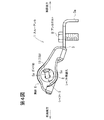
第12図は、スルーアンカが車両のピラー部に取り付けられた態様を示すシートベルト装置の斜視図、第13図はこの態様におけるスルーアンカの側面図である。 FIG. 12 is a perspective view of the seat belt device showing a mode in which the through anchor is attached to the pillar portion of the vehicle, and FIG. 13 is a side view of the through anchor in this mode.
この実施の形態では、スルーアンカ1は、シャフト5の延在方向を略車両前後方向として、車体のピラー部Pに設置されている。このスルーアンカ1のアンカベース3は、シャフト受部4,4側を下方とし、ボルト挿通孔7側を上方として配置され、該ボルト挿通孔7を介してアンカボルトBによりピラー部Pに対し略車両前後方向に回動可能に連結されている。
In this embodiment, the through anchor 1 is installed in the pillar portion P of the vehicle body, with the extending direction of the
この実施の形態では、スルーアンカ1の下方にリトラクタ24が設置されている。このリトラクタ24からエアベルト20が上方へ引き出され、次いで筒体6の車外側から該筒体6の上側を通って該筒体6の車室内側へ回り込むように該筒体6に掛けられ、その後、該筒体6から下方且つ座席(図示略)の前方に引き回されている。
In this embodiment, a
第13図の通り、この実施の形態では、該シャフト5のガイド面5aは、略上下方向に延在しており、且つ上端側ほど車室内側となるように若干傾斜している。
As shown in FIG. 13, in this embodiment, the
なお、詳しい図示は省略するが、この実施の形態でも、該ガイド面5aは、エアベルト20が座席乗員(図示略)の前面側に引き回され、バックル装置27にラッチされた状態における、該エアベルト20の筒体6よりもリトラクタ24側の部分の延在方向と、該エアベルト20の筒体6よりも乗員側の部分の延在方向との交叉角の二等分線と略平行方向に延在している。この実施の形態でも、該エアベルト20の筒体6よりもリトラクタ24側の部分の延在方向及び該エアベルト20の筒体6よりも乗員側の部分の延在方向と、該二等分線との交叉角は、それぞれ、16〜28°程度、特に20°程度であることが好ましい。
Although not shown in detail, also in this embodiment, the
この実施の形態のその他の構成は、前述の第1〜11図の実施の形態と同様であり、第12,13図において第1〜11図と同一符号は同一部分を示している。 The other configuration of this embodiment is the same as that of the above-described embodiment shown in FIGS. 1 to 11. In FIGS. 12 and 13, the same reference numerals as those in FIGS. 1 to 11 denote the same parts.
この実施の形態におけるスルーアンカ1の作動は、シャフト5の延在方向が略車両前後方向となり、エアベルト20から筒体6に作用する押圧力が略上下方向となったこと以外は、第1〜11図の実施の形態と同様である。
The operation of the through anchor 1 in this embodiment is the first to the second except that the extending direction of the
上記の各実施の形態は本発明の一例を示すものであり、本発明は上記の各実施の形態に限定されない。 Each of the above embodiments shows an example of the present invention, and the present invention is not limited to each of the above embodiments.
例えば、本発明においては、スルーアンカの掛軸(筒体)に掛けられるシートベルトは、エアベルトではなく、通常の非膨張式のシートベルトであってもよい。この場合、筒体6の外面の凹溝13は省略されてもよい。
For example, in the present invention, the seat belt hung on the through shaft (cylinder) of the through anchor may be a normal non-inflatable seat belt instead of an air belt. In this case, the
1 スルーアンカ
2 掛軸
3 アンカベース
4 シャフト受部
5 シャフト
5a ガイド面
6 筒体
8 シャフト挿通孔
9 ベアリング
10 シャフト挿通孔
11 板バネ
12 凹部
20 シートベルトとしてのエアベルト
21 ショルダーベルト部
24 リトラクタ
DESCRIPTION OF SYMBOLS 1 Through anchor 2 Hanging shaft 3 Anchor base 4
Claims (8)
該掛軸は、該アンカベースに回転不能に両端が支持されたシャフトと、該シャフトに回転可能に外嵌した筒体とを備えており、
シートベルトから該筒体に対し所定以上の押圧力が加えられた場合に該筒体の回転を阻止するストッパ機構が設けられたシートベルトのスルーアンカにおいて、
該ストッパ機構は、
該シャフトの外周面及び筒体の内周面の一方に設けられた凸部と、他方に設けられた、該凸部が係合可能な凹部と、
該筒体とシャフトとの間に配置されており、シートベルトから該筒体に対する押圧力が所定値よりも小さい場合には該凹部と凸部とが離隔するように該筒体を付勢するバネと
を備え、
シートベルトから該筒体に対し該所定値以上の押圧力が加えられた場合には、該筒体が該シャフトに接近して該凸部と凹部とが係合し、これにより該筒体の回転が阻止されるシートベルトのスルーアンカであって、
該筒体の軸心線方向の両端側にそれぞれベアリングが回転可能に内嵌しており、
各ベアリングは、該シャフトに対し回転不能に且つ該筒体の該シャフトに対する接近及び離反方向に摺動可能に保持されており、
各ベアリングが該筒体の該シャフトに対する接近方向に摺動することにより、該筒体が該シャフトに接近して前記凸部と凹部とが係合するように構成されており、
前記バネは、各ベアリングを、該筒体の該シャフトに対する離反方向に付勢していることを特徴とするシートベルトのスルーアンカ。 A through anchor of a seat belt having a hanging shaft on which a seat belt drawn from a retractor is hung, and an anchor base that supports both ends of the hanging shaft,
The hanging shaft includes a shaft whose both ends are supported by the anchor base so as not to rotate, and a cylindrical body rotatably fitted on the shaft.
In a through anchor of a seat belt provided with a stopper mechanism that prevents rotation of the cylinder when a predetermined pressing force is applied from the seat belt to the cylinder,
The stopper mechanism is
A convex portion provided on one of the outer peripheral surface of the shaft and the inner peripheral surface of the cylindrical body, and a concave portion provided on the other, to which the convex portion can be engaged,
The cylinder is arranged between the cylinder and the shaft, and when the pressing force against the cylinder from the seat belt is smaller than a predetermined value, the cylinder is urged so that the concave portion and the convex portion are separated from each other. With springs,
When a pressing force equal to or greater than the predetermined value is applied from the seat belt to the cylindrical body, the cylindrical body approaches the shaft and the convex portion and the concave portion engage with each other. A through anchor for the seat belt that prevents rotation ,
Bearings are fitted in both ends of the cylindrical body in the axial direction so as to be rotatable,
Each bearing is held so as to be non-rotatable with respect to the shaft and slidable in the approach and separation directions of the cylindrical body with respect to the shaft,
Each of the bearings slides in a direction in which the cylindrical body approaches the shaft, so that the cylindrical body approaches the shaft and the convex portion and the concave portion engage with each other.
A through anchor for a seat belt, wherein the spring urges each bearing in a direction away from the shaft of the cylindrical body .
該シャフトの外面のうち、該シャフトの該断面の長辺方向に延在する1対の側面は、前記筒体の該シャフトに対する接近及び離反方向に延在した、該筒体の移動を案内するガイド面となっており、 Of the outer surface of the shaft, a pair of side surfaces extending in the long side direction of the cross section of the shaft guide the movement of the cylinder extending in the approaching and separating directions of the cylinder. It is a guide surface,
該筒体は、内径が該シャフトの該断面の対角線方向の幅よりも大きなものとなっており、 The cylindrical body has an inner diameter larger than the diagonal width of the cross section of the shaft,
前記ベアリングに、それぞれ、該シャフトが挿通されたシャフト挿通孔が設けられており、 Each of the bearings is provided with a shaft insertion hole through which the shaft is inserted,
各シャフト挿通孔は、略長方形の開口形状を有したものとなっており、 Each shaft insertion hole has a substantially rectangular opening shape,
各シャフト挿通孔の短辺方向の幅は、該シャフトの該断面の短辺方向の幅と同等か、又は、該シャフトの該断面の短辺方向の幅よりも大きく且つ該シャフトの該断面の長辺方向の幅よりも小さなものとなっており、 The width in the short side direction of each shaft insertion hole is equal to the width in the short side direction of the cross section of the shaft or larger than the width in the short side direction of the cross section of the shaft and the cross section of the shaft. It is smaller than the width in the long side direction,
各シャフト挿通孔の長辺方向の幅は、該シャフトの該断面の長辺方向の幅よりも所定幅大きなものとなっており、 The width in the long side direction of each shaft insertion hole is a predetermined width larger than the width in the long side direction of the cross section of the shaft,
各シャフト挿通孔に対し、該シャフトは、その断面の長辺方向を各シャフト挿通孔の長辺方向として挿通されており、これにより、各ベアリングは、該シャフトに対し回転不能に保持されると共に、該シャフトの前記ガイド面に沿って摺動可能となっており、 For each shaft insertion hole, the shaft is inserted such that the long side direction of the cross section is the long side direction of each shaft insertion hole, whereby each bearing is held non-rotatably with respect to the shaft. Slidable along the guide surface of the shaft,
各シャフト挿通孔は、該シャフト挿通孔の長辺方向の一端側の縁部に該シャフトが当接した状態において、該筒体が各ベアリングによって該シャフトに対し略同軸状に支持されるように配置されており、 Each shaft insertion hole is configured so that the cylindrical body is supported substantially coaxially with respect to the shaft by each bearing in a state where the shaft is in contact with an edge portion on one end side in the long side direction of the shaft insertion hole. Has been placed,
前記バネは、各ベアリングを、該シャフト挿通孔の長辺方向の他端側に付勢していることを特徴とするシートベルトのスルーアンカ。 A through anchor for a seat belt, wherein the spring urges each bearing to the other end side in the long side direction of the shaft insertion hole.
該ガイド面は、前記シートベルトが座席着座者に装着された状態における、該シートベルトの該筒体よりも前記リトラクタ側の部分の延在方向L1と、該シートベルトの該筒体よりも座席着座者側の部分の延在方向L2との交叉角θの二等分線L3と略平行方向に延在していることを特徴とするシートベルトのスルーアンカ。 4. The shaft according to claim 1, wherein the shaft includes a guide surface that guides movement of the cylindrical body, and the cylindrical body approaches and separates from the shaft along the guide surface. Can be moved to
The guide surface is in a state where the seat belt is attached to the seat occupant, the extending direction L 1 of the retractor-side portion than the tube body of the seat belt, than the tubular body of the seat belt through anchor of the seat belt, characterized in that extending substantially in the direction parallel to the bisector L 3 crossover angle θ of the extending direction L 2 of the portions of the seat occupant side.
Priority Applications (5)
| Application Number | Priority Date | Filing Date | Title |
|---|---|---|---|
| JP2007258856A JP5125375B2 (en) | 2007-10-02 | 2007-10-02 | Seat belt through anchor, seat belt device and vehicle |
| EP08016272A EP2045149B1 (en) | 2007-10-02 | 2008-09-16 | Seat belt through anchor, seat belt apparatus and vehicle |
| DE602008004962T DE602008004962D1 (en) | 2007-10-02 | 2008-09-16 | Seat belt deflection fitting, seat belt device and vehicle with a safety belt device |
| US12/232,666 US7748744B2 (en) | 2007-10-02 | 2008-09-22 | Seat belt apparatus |
| CN2008101681476A CN101402346B (en) | 2007-10-02 | 2008-09-28 | Seat belt through anchor, seat belt apparatus and vehicle |
Applications Claiming Priority (1)
| Application Number | Priority Date | Filing Date | Title |
|---|---|---|---|
| JP2007258856A JP5125375B2 (en) | 2007-10-02 | 2007-10-02 | Seat belt through anchor, seat belt device and vehicle |
Publications (2)
| Publication Number | Publication Date |
|---|---|
| JP2009083779A JP2009083779A (en) | 2009-04-23 |
| JP5125375B2 true JP5125375B2 (en) | 2013-01-23 |
Family
ID=39800504
Family Applications (1)
| Application Number | Title | Priority Date | Filing Date |
|---|---|---|---|
| JP2007258856A Expired - Fee Related JP5125375B2 (en) | 2007-10-02 | 2007-10-02 | Seat belt through anchor, seat belt device and vehicle |
Country Status (5)
| Country | Link |
|---|---|
| US (1) | US7748744B2 (en) |
| EP (1) | EP2045149B1 (en) |
| JP (1) | JP5125375B2 (en) |
| CN (1) | CN101402346B (en) |
| DE (1) | DE602008004962D1 (en) |
Families Citing this family (14)
| Publication number | Priority date | Publication date | Assignee | Title |
|---|---|---|---|---|
| JP5244751B2 (en) * | 2009-09-18 | 2013-07-24 | トヨタ自動車株式会社 | Vehicle occupant restraint system |
| JP5529487B2 (en) * | 2009-10-07 | 2014-06-25 | タカタ株式会社 | Air belt device |
| DE102012000486A1 (en) * | 2012-01-13 | 2013-07-18 | Daimler Ag | Retractor for winding partially multi-layered seat belt of motor car, has supporting surfaces spaced apart from rotational axis, where input clearances are produced between surfaces to form rectilinearly extending portion of winding path |
| CN102874207A (en) * | 2012-10-22 | 2013-01-16 | 宜兴市奥华汽配有限公司 | Single end strip of automobile safety belt and preparation method thereof |
| DE102013205776B4 (en) * | 2013-04-02 | 2021-03-04 | Autoliv Development Ab | Deflector for a seat belt device with a two-layer or multi-layer inflatable seat belt |
| CN103253227A (en) * | 2013-05-29 | 2013-08-21 | 宜兴市奥华汽配有限公司 | Safety belt end piece with flanged square hole |
| US9260076B2 (en) * | 2013-07-23 | 2016-02-16 | Honda Motor Co., Ltd. | Method, system and apparatus for stabilizing vehicle occupant's shoulder during side collision impact |
| CN104442682B (en) * | 2014-11-03 | 2020-02-21 | 宁波市镇海西门专利技术开发有限公司 | Belt stopping device of belt buckle |
| DE102014017788B4 (en) * | 2014-12-03 | 2020-03-26 | Trw Automotive Gmbh | Tongue |
| JP6325040B2 (en) * | 2016-08-29 | 2018-05-16 | 株式会社東海理化電機製作所 | Mobile device |
| JP2018047745A (en) * | 2016-09-20 | 2018-03-29 | タカタ株式会社 | Tongue and seat belt device |
| US10793102B2 (en) * | 2018-10-12 | 2020-10-06 | Ford Global Technologies, Llc | Seat belt webbing guide |
| DE102018220620B4 (en) | 2018-11-29 | 2022-10-13 | Joyson Safety Systems Germany Gmbh | Belt deflection device |
| CN112824162A (en) * | 2019-11-20 | 2021-05-21 | 奥托立夫开发公司 | Safety belt assembly |
Family Cites Families (11)
| Publication number | Priority date | Publication date | Assignee | Title |
|---|---|---|---|---|
| US4993746A (en) * | 1989-09-05 | 1991-02-19 | Ford Motor Company | Locking frictional D-ring |
| US5415433A (en) * | 1993-07-30 | 1995-05-16 | Alliedsignal Inc. | Seat belt roller D-ring |
| DE29502192U1 (en) | 1995-02-10 | 1995-05-04 | Trw Repa Gmbh | Deflection fitting for seat belts |
| WO1999006249A1 (en) * | 1997-07-29 | 1999-02-11 | Autoliv Development Ab | Safety belt system with pre-tensioning device for secondary collision |
| US6250684B1 (en) * | 1998-10-01 | 2001-06-26 | Trw Vehicle Safety Systems Inc. | D-ring/roller assembly for supporting seat belt webbing in a vehicle |
| US6446897B1 (en) * | 1999-03-04 | 2002-09-10 | Nsk Ltd. | Seat belt system |
| DE19913423C1 (en) * | 1999-03-25 | 2000-05-11 | Autoliv Dev | Guide device for vehicle seat belts comprises side arms of sheet metal yoke connected by trough which holds guide roller with play but which adjoins trough under load through rotary bearings |
| JP2001213270A (en) * | 2000-02-04 | 2001-08-07 | Osamu Ishihara | Stopper and stopping method for re-winding seat belt |
| JP4120616B2 (en) * | 2004-04-30 | 2008-07-16 | 日産自動車株式会社 | Seat belt locking device |
| US7370822B2 (en) * | 2004-07-28 | 2008-05-13 | Takata Corporation | Seatbelt retractor having multi-level load-limit setting devices |
| JP5011779B2 (en) | 2005-04-04 | 2012-08-29 | タカタ株式会社 | Air belt device |
-
2007
- 2007-10-02 JP JP2007258856A patent/JP5125375B2/en not_active Expired - Fee Related
-
2008
- 2008-09-16 DE DE602008004962T patent/DE602008004962D1/en active Active
- 2008-09-16 EP EP08016272A patent/EP2045149B1/en not_active Expired - Fee Related
- 2008-09-22 US US12/232,666 patent/US7748744B2/en not_active Expired - Fee Related
- 2008-09-28 CN CN2008101681476A patent/CN101402346B/en not_active Expired - Fee Related
Also Published As
| Publication number | Publication date |
|---|---|
| US7748744B2 (en) | 2010-07-06 |
| CN101402346A (en) | 2009-04-08 |
| DE602008004962D1 (en) | 2011-03-31 |
| EP2045149A2 (en) | 2009-04-08 |
| JP2009083779A (en) | 2009-04-23 |
| EP2045149B1 (en) | 2011-02-16 |
| CN101402346B (en) | 2012-08-08 |
| EP2045149A3 (en) | 2009-11-25 |
| US20090085341A1 (en) | 2009-04-02 |
Similar Documents
| Publication | Publication Date | Title |
|---|---|---|
| JP5125375B2 (en) | Seat belt through anchor, seat belt device and vehicle | |
| EP3718833B1 (en) | Passenger restraint device | |
| US9758127B1 (en) | Restraint system | |
| US20060170199A1 (en) | Belt guide apparatus for a seatbelt restraint system of a vehicle | |
| US8002358B2 (en) | Seatbelt system | |
| US20200254953A1 (en) | Modular restraint seat for vehicle with one or more integrated safety features | |
| US20170259774A1 (en) | Vehicle Occupant Restraint Device | |
| US7131667B2 (en) | Seat belt pretensioner | |
| JP5990538B2 (en) | Rocking tongue | |
| US7988196B2 (en) | Lap loop three point seatbelt system | |
| JP2009166569A (en) | Occupant restraint system for vehicle | |
| US20100164207A1 (en) | Airbelt apparatus for vehicle | |
| JP2023032981A (en) | Air bag device for vehicle | |
| JP4917323B2 (en) | Crew protection device | |
| JP6529808B2 (en) | Buckle device and seat belt device provided with the buckle device | |
| JP2009179149A (en) | Airbag device | |
| JP2011051448A (en) | Seat belt device | |
| JP4687300B2 (en) | Crew restraint system | |
| JP2007261512A (en) | Rear collision air bag device | |
| JP2010058744A (en) | Occupant restraint system for vehicle | |
| JP2007245786A (en) | Seat belt device | |
| JP2001163148A (en) | Guide device for air belt | |
| JP2013230734A (en) | Tongue for seat belt device and seat belt device | |
| JP2007253732A (en) | Seat belt device | |
| JP2010036693A (en) | Occupant crash protection system |
Legal Events
| Date | Code | Title | Description |
|---|---|---|---|
| A621 | Written request for application examination |
Free format text: JAPANESE INTERMEDIATE CODE: A621 Effective date: 20100727 |
|
| A977 | Report on retrieval |
Free format text: JAPANESE INTERMEDIATE CODE: A971007 Effective date: 20120216 |
|
| A131 | Notification of reasons for refusal |
Free format text: JAPANESE INTERMEDIATE CODE: A131 Effective date: 20120306 |
|
| A521 | Written amendment |
Free format text: JAPANESE INTERMEDIATE CODE: A523 Effective date: 20120426 |
|
| TRDD | Decision of grant or rejection written | ||
| A01 | Written decision to grant a patent or to grant a registration (utility model) |
Free format text: JAPANESE INTERMEDIATE CODE: A01 Effective date: 20121002 |
|
| A01 | Written decision to grant a patent or to grant a registration (utility model) |
Free format text: JAPANESE INTERMEDIATE CODE: A01 |
|
| A61 | First payment of annual fees (during grant procedure) |
Free format text: JAPANESE INTERMEDIATE CODE: A61 Effective date: 20121015 |
|
| R150 | Certificate of patent or registration of utility model |
Free format text: JAPANESE INTERMEDIATE CODE: R150 |
|
| FPAY | Renewal fee payment (event date is renewal date of database) |
Free format text: PAYMENT UNTIL: 20151109 Year of fee payment: 3 |
|
| R250 | Receipt of annual fees |
Free format text: JAPANESE INTERMEDIATE CODE: R250 |
|
| R250 | Receipt of annual fees |
Free format text: JAPANESE INTERMEDIATE CODE: R250 |
|
| R250 | Receipt of annual fees |
Free format text: JAPANESE INTERMEDIATE CODE: R250 |
|
| S111 | Request for change of ownership or part of ownership |
Free format text: JAPANESE INTERMEDIATE CODE: R313113 |
|
| S343 | Written request for registration of root pledge or change of root pledge |
Free format text: JAPANESE INTERMEDIATE CODE: R316354 |
|
| SZ02 | Written request for trust registration |
Free format text: JAPANESE INTERMEDIATE CODE: R316Z02 |
|
| S343 | Written request for registration of root pledge or change of root pledge |
Free format text: JAPANESE INTERMEDIATE CODE: R316354 |
|
| R350 | Written notification of registration of transfer |
Free format text: JAPANESE INTERMEDIATE CODE: R350 |
|
| S343 | Written request for registration of root pledge or change of root pledge |
Free format text: JAPANESE INTERMEDIATE CODE: R316354 |
|
| SZ02 | Written request for trust registration |
Free format text: JAPANESE INTERMEDIATE CODE: R316Z02 |
|
| R350 | Written notification of registration of transfer |
Free format text: JAPANESE INTERMEDIATE CODE: R350 |
|
| LAPS | Cancellation because of no payment of annual fees |