JP5125009B2 - Zoom lens, imaging device, zoom lens vibration isolation method, zoom lens zoom method - Google Patents
Zoom lens, imaging device, zoom lens vibration isolation method, zoom lens zoom method Download PDFInfo
- Publication number
- JP5125009B2 JP5125009B2 JP2006198453A JP2006198453A JP5125009B2 JP 5125009 B2 JP5125009 B2 JP 5125009B2 JP 2006198453 A JP2006198453 A JP 2006198453A JP 2006198453 A JP2006198453 A JP 2006198453A JP 5125009 B2 JP5125009 B2 JP 5125009B2
- Authority
- JP
- Japan
- Prior art keywords
- lens group
- lens
- group
- end state
- refractive power
- Prior art date
- Legal status (The legal status is an assumption and is not a legal conclusion. Google has not performed a legal analysis and makes no representation as to the accuracy of the status listed.)
- Expired - Fee Related
Links
Images


Landscapes
- Lenses (AREA)
- Adjustment Of Camera Lenses (AREA)
Description
本発明は、ズームレンズ、撮像装置、ズームレンズの防振方法、ズームレンズの変倍方法に関するものである。 The present invention relates to a zoom lens, an imaging apparatus, a zoom lens image stabilization method, and a zoom lens zoom method.
従来、防振機能を有するズームレンズが提案されている(例えば、特許文献1を参照。)。
従来のズームレンズは、変倍比が小さく、高変倍化の要求に十分に応えることができない。そして、広角端状態における画角が狭いため、広画角化の要求にも十分に応えることができない。 Conventional zoom lenses have a low zoom ratio and cannot fully meet the demand for high zoom ratios. Since the angle of view in the wide-angle end state is narrow, it is not possible to sufficiently meet the demand for wide angle of view.
そこで本発明は上記問題点に鑑みてなされたものであり、高変倍と広画角を備えた防振機能を有するズームレンズ、撮像装置、ズームレンズの防振方法、ズームレンズの変倍方法を提供する。 Accordingly, the present invention has been made in view of the above problems, and has a zoom lens, an image pickup apparatus, a zoom lens image stabilization method, and a zoom lens magnification method having an image stabilization function having a high zoom ratio and a wide angle of view. I will provide a.
上記課題を解決するために本発明は、
物体側から順に、正の屈折力を有する第1レンズ群と、負の屈折力を有する第2レンズ群と、正の屈折力を有する第3レンズ群と、正の屈折力を有する第4レンズ群とにより、実質的に4個のレンズ群からなり、
広角端状態から望遠端状態への変倍に際して、前記第1レンズ群と前記第2レンズ群との間隔が増大し、前記第2レンズ群と前記第3レンズ群との間隔が減少し、前記第3レンズ群と前記第4レンズ群との間隔が変化し、
前記第3レンズ群は、物体側から順に、正の屈折力を有する前群と、負の屈折力を有する後群とにより、実質的に2個の群からなり、
前記後群のみを手ぶれ発生時の像面補正用に光軸に対し直交する方向に移動可能に構成し、
さらに以下の条件式を満足することを特徴とするズームレンズを提供する。
2.95<f3/fw<8.0
−0.270≦f2/f3<−0.100
但し、
fw:広角端状態における前記ズームレンズの焦点距離
f2:前記第2レンズ群の焦点距離
f3:前記第3レンズ群の焦点距離
また本発明は、
物体側から順に、正の屈折力を有する第1レンズ群と、負の屈折力を有する第2レンズ群と、正の屈折力を有する第3レンズ群と、正の屈折力を有する第4レンズ群とにより、実質的に4個のレンズ群からなり、
広角端状態から望遠端状態への変倍に際して、前記第1レンズ群と前記第2レンズ群との間隔が増大し、前記第2レンズ群と前記第3レンズ群との間隔が減少し、前記第3レンズ群と前記第4レンズ群との間隔が変化し、前記第1レンズ群と前記第3レンズ群と前記第4レンズ群とが物体側へ移動し、
前記第3レンズ群は、物体側から順に、正の屈折力を有する前群と、負の屈折力を有する後群とにより、実質的に2個の群からなり、
前記後群のみを手ぶれ発生時の像面補正用に光軸に対し直交する方向に移動可能に構成し、
さらに以下の条件式を満足することを特徴とするズームレンズを提供する。
2.95<f3/fw<8.0
1.4<f3/f4<5.0
但し、
fw:広角端状態における前記ズームレンズの焦点距離
f3:前記第3レンズ群の焦点距離
f4:前記第4レンズ群の焦点距離
また本発明は、
物体側から順に、正の屈折力を有する第1レンズ群と、負の屈折力を有する第2レンズ群と、正の屈折力を有する第3レンズ群と、正の屈折力を有する第4レンズ群とにより、実質的に4個のレンズ群からなり、
広角端状態から望遠端状態への変倍に際して、前記第1レンズ群と前記第2レンズ群との間隔が増大し、前記第2レンズ群と前記第3レンズ群との間隔が減少し、前記第3レンズ群と前記第4レンズ群との間隔が変化し、前記第1レンズ群と前記第3レンズ群と前記第4レンズ群とが物体側へ移動し、
前記第3レンズ群は、物体側から順に、正の屈折力を有する前群と、負の屈折力を有する後群とにより、実質的に2個の群からなり、
前記後群のみを手ぶれ発生時の像面補正用に光軸に対し直交する方向に移動可能に構成し、
前記第3レンズ群の物体側近傍には、開口絞りが備えられ、
前記開口絞りは、広角端状態から望遠端状態への変倍に際して、前記第3レンズ群と一体的に移動し、
さらに以下の条件式を満足することを特徴とするズームレンズを提供する。
2.95<f3/fw<8.0
1.4<f3/f4<5.0
但し、
fw:広角端状態における前記ズームレンズの焦点距離
f3:前記第3レンズ群の焦点距離
f4:前記第4レンズ群の焦点距離
In order to solve the above problems, the present invention
In order from the object side, a first lens group having a positive refractive power, a second lens group having a negative refractive power, a third lens group having a positive refractive power, and a fourth lens having a positive refractive power Depending on the group, it consists essentially of four lens groups,
Upon zooming from the wide-angle end state to the telephoto end state, the distance between the first lens group and the second lens group increases, the distance between the second lens group and the third lens group decreases, The distance between the third lens group and the fourth lens group changes,
The third lens group, in order from the object side, consists of two groups of a front group having a positive refractive power and a rear group having a negative refractive power,
Against the optical axis for image plane correction upon occurrence camera shake only the rear group is movable in the linear direction orthogonal,
Furthermore, a zoom lens characterized by satisfying the following conditional expression is provided.
2.95 <f3 / fw <8.0
−0.270 ≦ f2 / f3 <−0.100
However,
fw: focal length of the zoom lens in the wide-angle end state f2: focal length of the second lens group f3: focal length of the third lens group
In order from the object side, a first lens group having a positive refractive power, a second lens group having a negative refractive power, a third lens group having a positive refractive power, and a fourth lens having a positive refractive power Depending on the group, it consists essentially of four lens groups,
Upon zooming from the wide-angle end state to the telephoto end state, the distance between the first lens group and the second lens group increases, the distance between the second lens group and the third lens group decreases, The distance between the third lens group and the fourth lens group changes, and the first lens group, the third lens group, and the fourth lens group move toward the object side,
The third lens group, in order from the object side, consists of two groups of a front group having a positive refractive power and a rear group having a negative refractive power,
Against the optical axis for image plane correction upon occurrence camera shake only the rear group is movable in the linear direction orthogonal,
Furthermore, a zoom lens characterized by satisfying the following conditional expression is provided.
2.95 <f3 / fw <8.0
1.4 <f3 / f4 <5.0
However,
fw: focal length of the zoom lens in the wide-angle end state f3: focal length of the third lens group f4: focal length of the fourth lens group
In order from the object side, a first lens group having a positive refractive power, a second lens group having a negative refractive power, a third lens group having a positive refractive power, and a fourth lens having a positive refractive power Depending on the group, it consists essentially of four lens groups,
Upon zooming from the wide-angle end state to the telephoto end state, the distance between the first lens group and the second lens group increases, the distance between the second lens group and the third lens group decreases, The distance between the third lens group and the fourth lens group changes, and the first lens group, the third lens group, and the fourth lens group move toward the object side,
The third lens group, in order from the object side, consists of two groups of a front group having a positive refractive power and a rear group having a negative refractive power,
Against the optical axis for image plane correction upon occurrence camera shake only the rear group is movable in the linear direction orthogonal,
An aperture stop is provided near the object side of the third lens group,
The aperture stop moves integrally with the third lens group upon zooming from the wide-angle end state to the telephoto end state,
Furthermore, a zoom lens characterized by satisfying the following conditional expression is provided.
2.95 <f3 / fw <8.0
1.4 <f3 / f4 <5.0
However,
fw: focal length of the zoom lens in the wide-angle end state f3: focal length of the third lens group f4: focal length of the fourth lens group
また本発明のズームレンズを搭載したことを特徴とする撮像装置を提供する。 Also provided is an image pickup apparatus equipped with the zoom lens of the present invention.
また本発明は、
物体側から順に、正の屈折力を有する第1レンズ群と、負の屈折力を有する第2レンズ群と、正の屈折力を有する第3レンズ群と、正の屈折力を有する第4レンズ群とにより、実質的に4個のレンズ群からなるズームレンズの防振方法であって、
広角端状態から望遠端状態への変倍に際して、前記第1レンズ群と前記第2レンズ群との間隔が増大し、前記第2レンズ群と前記第3レンズ群との間隔が減少し、前記第3レンズ群と前記第4レンズ群との間隔が変化し、
前記第3レンズ群は、物体側から順に、正の屈折力を有する前群と、負の屈折力を有する後群とにより、実質的に2個の群からなり、
前記後群のみを手ぶれ発生時の像面補正用に光軸に対し直交する方向に移動可能に構成し、
さらに以下の条件式を満足することを特徴とするズームレンズの防振方法を提供する。
2.95<f3/fw<8.0
−0.270≦f2/f3<−0.100
但し、
fw:広角端状態における前記ズームレンズの焦点距離
f2:前記第2レンズ群の焦点距離
f3:前記第3レンズ群の焦点距離
The present invention also provides
In order from the object side, a first lens group having a positive refractive power, a second lens group having a negative refractive power, a third lens group having a positive refractive power, and a fourth lens having a positive refractive power A zoom lens stabilization method comprising substantially four lens groups,
Upon zooming from the wide-angle end state to the telephoto end state, the distance between the first lens group and the second lens group increases, the distance between the second lens group and the third lens group decreases, The distance between the third lens group and the fourth lens group changes,
The third lens group, in order from the object side, consists of two groups of a front group having a positive refractive power and a rear group having a negative refractive power,
Against the optical axis for image plane correction upon occurrence camera shake only the rear group is movable in the linear direction orthogonal,
Furthermore, the present invention provides a vibration isolating method for a zoom lens that satisfies the following conditional expression.
2.95 <f3 / fw <8.0
−0.270 ≦ f2 / f3 <−0.100
However,
fw: focal length of the zoom lens in the wide-angle end state f2: focal length of the second lens group f3: focal length of the third lens group
また本発明は、
物体側から順に、正の屈折力を有する第1レンズ群と、負の屈折力を有する第2レンズ群と、正の屈折力を有する第3レンズ群と、正の屈折力を有する第4レンズ群とにより、実質的に4個のレンズ群からなるズームレンズの変倍方法において、
広角端状態から望遠端状態への変倍に際して、前記第1レンズ群と前記第2レンズ群との間隔が増大し、前記第2レンズ群と前記第3レンズ群との間隔が減少し、前記第3レンズ群と前記第4レンズ群との間隔が変化し、
前記第3レンズ群は、物体側から順に、正の屈折力を有する前群と、負の屈折力を有する後群とにより、実質的に2個の群からなり、
前記後群のみを手ぶれ発生時の像面補正用に光軸に対し直交する方向に移動可能に構成し、
さらに以下の条件式を満足することを特徴とするズームレンズの変倍方法を提供する。
2.95<f3/fw<8.0
−0.270≦f2/f3<−0.100
但し、
fw:広角端状態における前記ズームレンズの焦点距離
f2:前記第2レンズ群の焦点距離
f3:前記第3レンズ群の焦点距離
The present invention also provides
In order from the object side, a first lens group having a positive refractive power, a second lens group having a negative refractive power, a third lens group having a positive refractive power, and a fourth lens having a positive refractive power A zoom lens zooming method comprising substantially four lens groups,
Upon zooming from the wide-angle end state to the telephoto end state, the distance between the first lens group and the second lens group increases, the distance between the second lens group and the third lens group decreases, The distance between the third lens group and the fourth lens group changes,
The third lens group, in order from the object side, consists of two groups of a front group having a positive refractive power and a rear group having a negative refractive power,
Against the optical axis for image plane correction upon occurrence camera shake only the rear group is movable in the linear direction orthogonal,
Furthermore, a zoom lens zooming method characterized by satisfying the following conditional expression is provided.
2.95 <f3 / fw <8.0
−0.270 ≦ f2 / f3 <−0.100
However,
fw: focal length of the zoom lens in the wide-angle end state f2: focal length of the second lens group f3: focal length of the third lens group
本発明によれば、高変倍と広画角を備えた防振機能を有するズームレンズ、撮像装置、ズームレンズの防振方法、ズームレンズの変倍方法を提供することができる。 According to the present invention, it is possible to provide a zoom lens having an anti-vibration function having a high zoom ratio and a wide angle of view, an image pickup apparatus, an anti-shake method for the zoom lens, and a zoom lens zooming method.
以下、本発明の実施形態に係るズームレンズ、撮像装置、ズームレンズの防振方法、及びズームレンズの変倍方法について説明する。
本ズームレンズは、物体側から順に、正の屈折力を有する第1レンズ群と、負の屈折力を有する第2レンズ群と、正の屈折力を有する第3レンズ群と、正の屈折力を有する第4レンズ群とを有し、広角端状態から望遠端状態への変倍に際して、前記第1レンズ群と前記第2レンズ群との間隔が増大し、前記第2レンズ群と前記第3レンズ群との間隔が減少し、前記第3レンズ群と前記第4レンズ群との間隔が変化し、前記第3レンズ群は、物体側から順に、正の屈折力を有する前群と、負の屈折力を有する後群とからなり、前記後群のみを光軸と略直交する方向へ移動させることによって手ぶれ発生時の像面補正を行い、さらに以下の条件式(1)を満足する。
(1)2.95<f3/fw<8.0
但し、
fw:広角端状態における前記ズームレンズの焦点距離
f3:前記第3レンズ群の焦点距離
Hereinafter, a zoom lens, an imaging apparatus, a zoom lens image stabilization method, and a zoom lens zoom method according to an embodiment of the present invention will be described.
The zoom lens includes, in order from the object side, a first lens group having a positive refractive power, a second lens group having a negative refractive power, a third lens group having a positive refractive power, and a positive refractive power. And a distance between the first lens group and the second lens group is increased upon zooming from the wide-angle end state to the telephoto end state, and the second lens group and the second lens group The distance between the third lens group decreases, the distance between the third lens group and the fourth lens group changes, and the third lens group, in order from the object side, has a front group having a positive refractive power; An image plane is corrected when camera shake occurs by moving only the rear group in a direction substantially orthogonal to the optical axis, and further satisfies the following conditional expression (1). .
(1) 2.95 <f3 / fw <8.0
However,
fw: focal length of the zoom lens in the wide-angle end state f3: focal length of the third lens group
第3レンズ群は、他のレンズ群よりもレンズ径の小型化を図ることが可能であるため、防振機構が組み込まれることに適している。また、第3レンズを正の屈折力を有する前群と負の屈折力を有する後群とによって構成し、後群のみを防振用のレンズ群として用いることで、防振機構の小型化と防振レンズ群の質量の軽減を達成できる。そして、適切な屈折力配分とすることができるため、本ズームレンズにおいて手ぶれが発生した際に防振レンズ群である後群を光軸と略直交する方向へ移動させて像面補正を行った時、即ち防振時の結像性能の劣化を小さくすることができる。 Since the third lens group can be made smaller in lens diameter than the other lens groups, it is suitable for incorporating an anti-vibration mechanism. Further, the third lens is composed of a front group having a positive refractive power and a rear group having a negative refractive power, and only the rear group is used as a lens group for vibration isolation, thereby reducing the size of the vibration isolation mechanism. Reduction of the mass of the anti-vibration lens group can be achieved. Since the appropriate refractive power distribution can be achieved, the image plane correction is performed by moving the rear group, which is an anti-vibration lens group, in a direction substantially orthogonal to the optical axis when camera shake occurs in the zoom lens. It is possible to reduce the deterioration of the imaging performance at the time of image stabilization.
上記条件式(1)は、広角端状態における本ズームレンズの焦点距離に対する第3レンズ群の焦点距離を規定するものである。
条件式(1)の下限値を下回ると、広角端状態における非点収差と像面湾曲の劣化を招くこととなってしまう。なお、条件式(1)の下限値を3.00に設定すれば、本発明の効果をより確実なものとすることができる。
Conditional expression (1) defines the focal length of the third lens group with respect to the focal length of the zoom lens in the wide-angle end state.
If the lower limit of conditional expression (1) is not reached, the astigmatism and the curvature of field in the wide-angle end state will be deteriorated. If the lower limit value of conditional expression (1) is set to 3.00, the effect of the present invention can be made more reliable.
一方、条件式(1)の上限値を上回ると、第3レンズ群と第4レンズ群の移動量が大きくなるため本ズームレンズの小型化を達成することが困難になってしまう。そして、この影響を緩和するために第1レンズ群と第2レンズ群の屈折力を大きくすることは、望遠端状態における球面収差の劣化を招いてしまうため好ましくない。なお、条件式(1)の上限値を6.00に設定すれば、本発明の効果をより確実なものとすることができる。 On the other hand, if the upper limit value of conditional expression (1) is exceeded, the movement amount of the third lens group and the fourth lens group becomes large, and it becomes difficult to achieve downsizing of the zoom lens. In order to alleviate this influence, it is not preferable to increase the refractive power of the first lens group and the second lens group, since it causes deterioration of spherical aberration in the telephoto end state. If the upper limit value of conditional expression (1) is set to 6.00, the effect of the present invention can be made more reliable.
また本ズームレンズは、以下の条件式(2)を満足することが望ましい。
(2)0.56<f3/ft<2.0
但し、
ft:望遠端状態における前記ズームレンズの焦点距離
f3:前記第3レンズ群の焦点距離
In addition, it is desirable that the zoom lens satisfies the following conditional expression (2).
(2) 0.56 <f3 / ft <2.0
However,
ft: focal length of the zoom lens in the telephoto end state f3: focal length of the third lens group
条件式(2)は、望遠端状態における本ズームレンズの焦点距離に対する第3レンズ群の焦点距離を規定するものである。
条件式(2)の下限値を下回ると、レンズ群の相対的な偏心等の製造誤差によって生じる偏芯コマ収差が著しくなってしまうため好ましくない。また、望遠端状態における球面収差の劣化も招いてしまう。なお、条件式(2)の下限値を0.60に設定すれば、本発明の効果をより確実なものとすることができる。
Conditional expression (2) defines the focal length of the third lens group with respect to the focal length of the zoom lens in the telephoto end state.
If the lower limit value of conditional expression (2) is not reached, decentration coma aberration caused by manufacturing errors such as relative decentration of the lens group becomes significant, which is not preferable. In addition, the spherical aberration is deteriorated in the telephoto end state. If the lower limit value of conditional expression (2) is set to 0.60, the effect of the present invention can be made more reliable.
一方、条件式(2)の上限値を上回ると、本ズームレンズの全長及び直径が大型化し、実用に供することが困難になってしまう。またこれとともに、開口絞り機構や防振機構の大型化も招いてしまうため好ましくない。そしてこの影響を緩和するために第2レンズ群の屈折力を大きくすることは、広角端状態における非点収差と像面湾曲を悪化させてしまうため好ましくない。なお、条件式(2)の上限値を1.50に設定すれば、本発明の効果をより確実なものとすることができる。 On the other hand, if the upper limit value of conditional expression (2) is exceeded, the overall length and diameter of the zoom lens will increase, making it difficult to put to practical use. At the same time, the aperture stop mechanism and the vibration isolation mechanism are undesirably enlarged. In order to alleviate this effect, increasing the refractive power of the second lens unit is not preferable because it causes deterioration in astigmatism and field curvature in the wide-angle end state. If the upper limit value of conditional expression (2) is set to 1.50, the effect of the present invention can be made more reliable.
また本ズームレンズは、以下の条件式(3)を満足することが望ましい。
(3)−0.275<f2/f3<−0.100
但し、
f2:前記第2レンズ群の焦点距離
f3:前記第3レンズ群の焦点距離
In addition, it is desirable that the zoom lens satisfies the following conditional expression (3).
(3) -0.275 <f2 / f3 <-0.100
However,
f2: focal length of the second lens group f3: focal length of the third lens group
条件式(3)は、第3レンズ群の焦点距離に対する第2レンズ群の焦点距離を規定するものである。
条件式(3)の下限値を下回ると、広角端状態におけるコマ収差、望遠端状態における球面収差、及び防振時における像面湾曲の変動を同時に補正することが困難になってしまうため好ましくない。
Conditional expression (3) defines the focal length of the second lens group with respect to the focal length of the third lens group.
If the lower limit value of conditional expression (3) is not reached, it is difficult to simultaneously correct coma aberration in the wide-angle end state, spherical aberration in the telephoto end state, and field curvature variation during image stabilization. .
一方、条件式(3)の上限値を上回ると、第2レンズ群の屈折力が大きくなり、広角端状態における非点収差と像面湾曲の劣化が著しくなってしまうため好ましくない。なお、条件式(3)の上限値を−0.15に設定すれば、本発明の効果をより確実なものとすることができる。 On the other hand, if the upper limit value of conditional expression (3) is exceeded, the refractive power of the second lens group will increase, and astigmatism and field curvature will deteriorate significantly in the wide-angle end state, which is not preferable. In addition, if the upper limit of conditional expression (3) is set to -0.15, the effect of this invention can be made more reliable.
また本ズームレンズは、広角端状態から望遠端状態への変倍に際して、前記第1レンズ群と前記第3レンズ群と前記第4レンズ群とが物体側へ移動することが望ましい。
この構成によって、各レンズ群を移動させるための移動機構を簡単な構成にすることができ、本ズームレンズを小型化することが可能となる。
In the zoom lens, it is desirable that the first lens group, the third lens group, and the fourth lens group move toward the object side during zooming from the wide-angle end state to the telephoto end state.
With this configuration, a moving mechanism for moving each lens group can be simplified, and the zoom lens can be reduced in size.
また本ズームレンズは、以下の条件式(4)を満足することが望ましい。
(4)0<D3W−D3T
但し、
D3W:広角端状態における前記第3レンズ群と前記第4レンズ群との空気間隔
D3T:望遠端状態における前記第3レンズ群と前記第4レンズ群との空気間隔
In addition, it is desirable that the zoom lens satisfies the following conditional expression (4).
(4) 0 <D3W-D3T
However,
D3W: Air distance between the third lens group and the fourth lens group in the wide-angle end state D3T: Air distance between the third lens group and the fourth lens group in the telephoto end state
条件式(4)は、広角端状態における前記第3レンズ群と前記第4レンズ群との空気間隔と、望遠端状態における前記第3レンズ群と前記第4レンズ群との空気間隔との差を規定するものである。
条件式(4)の下限値を下回ると、広角端状態から望遠端状態へ移行する際の像面湾曲の変動を抑えることができなくなってしまうため好ましくない。なお、条件式(4)の下限値を2.0に設定すれば、本発明の効果をより確実なものとすることができる。
Conditional expression (4) is the difference between the air gap between the third lens group and the fourth lens group in the wide-angle end state and the air gap between the third lens group and the fourth lens group in the telephoto end state. It prescribes.
If the lower limit value of conditional expression (4) is not reached, it will not be possible to suppress fluctuations in field curvature when shifting from the wide-angle end state to the telephoto end state. If the lower limit value of conditional expression (4) is set to 2.0, the effect of the present invention can be made more reliable.
また本ズームレンズは、以下の条件式(5)を満足することが望ましい。
(5)0.24<f31/ft<0.41
但し、
ft :望遠端状態における前記ズームレンズの焦点距離
f31:前記前群の焦点距離
In addition, it is desirable that this zoom lens satisfies the following conditional expression (5).
(5) 0.24 <f31 / ft <0.41
However,
ft: focal length of the zoom lens in the telephoto end state f31: focal length of the front group
条件式(5)は、望遠端状態における本ズームレンズの焦点距離に対する前群の焦点距離を規定するものである。
条件式(5)の下限値を下回ると、防振時における後群の移動量に対する像の移動量が大きくなる。このため、後群の偏心制御が困難になり、わずかな偏心誤差によって結像性能が劣化し、偏芯コマ収差を補正することが困難になってしまう。
Conditional expression (5) defines the focal length of the front group with respect to the focal length of the zoom lens in the telephoto end state.
If the lower limit of conditional expression (5) is not reached, the amount of movement of the image with respect to the amount of movement of the rear group at the time of image stabilization increases. For this reason, it becomes difficult to control the decentering of the rear group, and the imaging performance deteriorates due to a slight decentering error, and it becomes difficult to correct the eccentric coma aberration.
一方、条件式(5)の上限値を上回ると、防振時における後群の移動量に対する像の移動量が小さくなる。このため、防振に必要な像の移動量を得るための後群の移動量が大きくなり、防振時における像面変動や偏芯コマ収差を補正することが困難になってしまう。なお、条件式(5)の上限値を0.38に設定すれば、本発明の効果をより確実なものとすることができる。 On the other hand, if the upper limit of conditional expression (5) is exceeded, the amount of movement of the image with respect to the amount of movement of the rear group during image stabilization becomes small. For this reason, the amount of movement of the rear group for obtaining the amount of movement of the image necessary for image stabilization increases, and it becomes difficult to correct image plane fluctuations and decentering coma during image stabilization. If the upper limit value of conditional expression (5) is set to 0.38, the effect of the present invention can be made more reliable.
また本ズームレンズは、以下の条件式(6)を満足することが望ましい。
(6)2.15<Bfw/fw<3.50
但し、
fw :広角端状態における前記ズームレンズの焦点距離
Bfw:広角端状態におけるバックフォーカス
In addition, it is desirable that the zoom lens satisfies the following conditional expression (6).
(6) 2.15 <Bfw / fw <3.50
However,
fw: focal length of the zoom lens in the wide-angle end state Bfw: back focus in the wide-angle end state
条件式(6)は、本ズームレンズをレンズ交換式のデジタル一眼レフカメラ用いる際に好適なバックフォーカスの範囲を規定するものである。
条件式(6)の上限値を上回ると、バックフォーカスが大きくなりすぎて、レンズ全長の大型化を招いてしまう。また、バックフォーカスを小さくしようとすれば、広角端状態における非点収差と像面湾曲が悪化してしまう。なお、条件式(6)の上限値を3.00に設定すれば、本発明の効果をより確実なものとすることができる。
Conditional expression (6) defines a back focus range that is suitable when the zoom lens is used with a lens interchangeable digital single-lens reflex camera.
If the upper limit value of conditional expression (6) is exceeded, the back focus becomes too large, leading to an increase in the total lens length. Further, if the back focus is reduced, astigmatism and field curvature in the wide-angle end state are deteriorated. In addition, if the upper limit of conditional expression (6) is set to 3.00, the effect of this invention can be made more reliable.
一方、条件式(6)の下限値を下回ると、バックフォーカスが小さくなり、本ズームレンズの像側部分、即ちレンズ後部と一眼レフカメラにおけるミラーとの干渉を招いてしまう。なお、条件式(6)の下限値を2.20に設定すれば、本発明の効果をより確実なものとすることができる。 On the other hand, if the lower limit value of conditional expression (6) is not reached, the back focus becomes small, causing interference between the image side portion of the zoom lens, that is, the rear portion of the lens and the mirror in the single-lens reflex camera. If the lower limit value of conditional expression (6) is set to 2.20, the effect of the present invention can be made more reliable.
また本ズームレンズは、以下の条件式(7)を満足することが望ましい。
(7)1.4<f3/f4<5.0
但し、
f3:前記第3レンズ群の焦点距離
f4:前記第4レンズ群の焦点距離
It is desirable that the zoom lens satisfies the following conditional expression (7).
(7) 1.4 <f3 / f4 <5.0
However,
f3: focal length of the third lens group f4: focal length of the fourth lens group
条件式(7)は、第3レンズ群の焦点距離と第4レンズ群の焦点距離を規定するものである。
条件式(7)の下限値を下回ると、第3レンズ群の屈折力が大きくなり、望遠端状態において球面収差の劣化を招いてしまう。
Conditional expression (7) defines the focal length of the third lens group and the focal length of the fourth lens group.
If the lower limit value of conditional expression (7) is not reached, the refractive power of the third lens unit will increase, and spherical aberration will be degraded in the telephoto end state.
一方、条件式(7)の上限値を上回ると、第4レンズ群の屈折力が大きくなり、像面湾曲及びコマ収差の補正が困難になってしまう。
なお、条件式(7)の上限値を3.0に設定すれば、本発明の効果をより確実なものとすることができる。
On the other hand, if the upper limit of conditional expression (7) is exceeded, the refractive power of the fourth lens group will increase, making it difficult to correct field curvature and coma.
If the upper limit value of conditional expression (7) is set to 3.0, the effect of the present invention can be made more reliable.
また本ズームレンズは、前記後群中の最も物体側のレンズ面が非球面であることが望ましい。
この構成により、後群に偏芯を与えたときにも偏芯コマ収差の劣化を十分に小さくすることができる。
In the zoom lens, it is preferable that the most object side lens surface in the rear group is an aspherical surface.
With this configuration, it is possible to sufficiently reduce the decentration coma aberration even when the rear group is decentered.
また本ズームレンズは、前記第4レンズ群中に少なくとも一つの非球面を有していることが望ましい。
この構成により、広角端状態における歪曲収差、像面湾曲、及び非点収差と、望遠端状態における球面収差、及びコマ収差とを良好に補正することができる。
The zoom lens preferably has at least one aspheric surface in the fourth lens group.
With this configuration, it is possible to satisfactorily correct distortion, field curvature, and astigmatism in the wide-angle end state, and spherical aberration and coma aberration in the telephoto end state.
また本ズームレンズは、前記第2レンズ群を光軸方向へ移動させることによって合焦を行うことが望ましい。
第2レンズ群の屈折力が大きいため、繰り出し量を小さくすることができる。これにより、本ズームレンズの全長が大型化することもない。また、第2レンズ群は第1レンズ群に比して軽量であるため、駆動機構への負担を軽減することができる。
In addition, it is desirable that the zoom lens performs focusing by moving the second lens group in the optical axis direction.
Since the refractive power of the second lens group is large, the feeding amount can be reduced. As a result, the entire length of the zoom lens is not increased. Further, since the second lens group is lighter than the first lens group, the burden on the drive mechanism can be reduced.
また本撮像装置は、上述した構成のズームレンズを備えている。
これにより、高変倍と広画角を備えた防振機能を有する撮像装置を実現することができる。
In addition, the imaging apparatus includes the zoom lens having the above-described configuration.
As a result, it is possible to realize an image pickup apparatus having an anti-vibration function having a high zoom ratio and a wide angle of view.
また本ズームレンズの防振方法は、物体側から順に、正の屈折力を有する第1レンズ群と、負の屈折力を有する第2レンズ群と、正の屈折力を有する第3レンズ群と、正の屈折力を有する第4レンズ群とを有するズームレンズの防振方法であって、広角端状態から望遠端状態への変倍に際して、前記第1レンズ群と前記第2レンズ群との間隔が増大し、前記第2レンズ群と前記第3レンズ群との間隔が減少し、前記第3レンズ群と前記第4レンズ群との間隔が変化し、前記第3レンズ群は、物体側から順に、正の屈折力を有する前群と、負の屈折力を有する後群とからなり、前記後群のみを光軸と略直交する方向へ移動させることによって手ぶれ発生時の像面補正を行い、さらに以下の条件式(1)を満足する。
(1)2.95<f3/fw<8.0
但し、
fw:広角端状態における前記ズームレンズの焦点距離
f3:前記第3レンズ群の焦点距離
これにより、防振機能を有するズームレンズの高変倍化と広画角化を実現することができる。
Further, the image stabilization method of the zoom lens includes, in order from the object side, a first lens group having a positive refractive power, a second lens group having a negative refractive power, and a third lens group having a positive refractive power. , And a fourth lens group having a positive refractive power, wherein the zoom lens includes a first lens group and a second lens group at the time of zooming from the wide-angle end state to the telephoto end state. The distance increases, the distance between the second lens group and the third lens group decreases, the distance between the third lens group and the fourth lens group changes, and the third lens group In order, from the front group having a positive refractive power and the rear group having a negative refractive power, only the rear group is moved in a direction substantially orthogonal to the optical axis to correct image plane when camera shake occurs. And the following conditional expression (1) is satisfied.
(1) 2.95 <f3 / fw <8.0
However,
fw: Focal length of the zoom lens in the wide-angle end state f3: Focal length of the third lens group Accordingly, it is possible to realize a high zoom ratio and a wide angle of view of the zoom lens having an anti-vibration function.
また本ズームレンズの変倍方法は、物体側から順に、正の屈折力を有する第1レンズ群と、負の屈折力を有する第2レンズ群と、正の屈折力を有する第3レンズ群と、正の屈折力を有する第4レンズ群とを有するズームレンズの変倍方法において、広角端状態から望遠端状態への変倍に際して、前記第1レンズ群と前記第2レンズ群との間隔が増大し、前記第2レンズ群と前記第3レンズ群との間隔が減少し、前記第3レンズ群と前記第4レンズ群との間隔が変化し、前記第3レンズ群は、物体側から順に、正の屈折力を有する前群と、負の屈折力を有する後群とからなり、前記後群のみを光軸と略直交する方向へ移動させることによって手ぶれ発生時の像面補正を行い、さらに以下の条件式(1)を満足する。
(1)2.95<f3/fw<8.0
但し、
fw:広角端状態における前記ズームレンズの焦点距離
f3:前記第3レンズ群の焦点距離
これにより、防振機能を有するズームレンズの高変倍化と広画角化を実現することができる。
The zoom lens zooming method includes, in order from the object side, a first lens group having a positive refractive power, a second lens group having a negative refractive power, and a third lens group having a positive refractive power. In the zoom lens zooming method including the fourth lens unit having a positive refractive power, an interval between the first lens unit and the second lens unit is set when zooming from the wide-angle end state to the telephoto end state. Increases, the distance between the second lens group and the third lens group decreases, the distance between the third lens group and the fourth lens group changes, and the third lens group is in order from the object side. The front group having a positive refractive power and the rear group having a negative refractive power, and performing image plane correction at the time of camera shake by moving only the rear group in a direction substantially orthogonal to the optical axis, Furthermore, the following conditional expression (1) is satisfied.
(1) 2.95 <f3 / fw <8.0
However,
fw: Focal length of the zoom lens in the wide-angle end state f3: Focal length of the third lens group Accordingly, it is possible to realize a high zoom ratio and a wide angle of view of the zoom lens having an image stabilization function.
以下、本実施形態の数値実施例に係るズームレンズを添付図面に基づいて説明する。
(第1実施例)
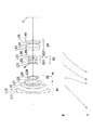
図1は、第1実施例に係るズームレンズの構成を示す図である。
本実施例に係るズームレンズは、物体側から順に、正の屈折力を有する第1レンズ群G1と、負の屈折力を有する第2レンズ群G2と、正の屈折力を有する第3レンズ群G3と、正の屈折力を有する第4レンズ群G4とから構成されている。
Hereinafter, zoom lenses according to numerical examples of the present embodiment will be described with reference to the accompanying drawings.
(First embodiment)
FIG. 1 is a diagram illustrating a configuration of a zoom lens according to the first example.
The zoom lens according to the present embodiment includes, in order from the object side, a first lens group G1 having a positive refractive power, a second lens group G2 having a negative refractive power, and a third lens group having a positive refractive power. G3 and a fourth lens group G4 having a positive refractive power.
第1レンズ群G1は、物体側から順に、物体側に凸面を向けた負メニスカスレンズL11と物体側に凸面を向けた正メニスカスレンズL12との接合レンズと、物体側に凸面を向けた正メニスカスレンズL13とからなる。
第2レンズ群G2は、物体側から順に、物体側に凸面を向けた負メニスカスレンズL21と、両凹形状の負レンズL22と、両凸形状の正レンズL23と、物体側に凹面を向けた負メニスカスレンズL24とからなる。また、第2レンズ群G2において最も物体側に位置する負メニスカスレンズL21は、物体側のガラスレンズ面に樹脂層を設けて非球面を形成した非球面レンズである。
The first lens group G1 includes, in order from the object side, a cemented lens of a negative meniscus lens L11 having a convex surface facing the object side and a positive meniscus lens L12 having a convex surface facing the object side, and a positive meniscus having a convex surface facing the object side. Lens L13.
The second lens group G2 has a negative meniscus lens L21 having a convex surface directed toward the object side, a biconcave negative lens L22, a biconvex positive lens L23, and a concave surface directed toward the object side, in order from the object side. And a negative meniscus lens L24. Further, the negative meniscus lens L21 located closest to the object side in the second lens group G2 is an aspheric lens in which an aspheric surface is formed by providing a resin layer on the glass lens surface on the object side.
第3レンズ群G3は、物体側から順に、正の屈折力を有する前群G31と、負の屈折力を有する後群G32とからなる。
前群G31は、物体側から順に、物体側に凹面を向けた正メニスカスレンズL31と、両凸形状の正レンズL32と物体側に凹面を向けた負メニスカスレンズL33との接合レンズとからなる。
後群G32は、物体側から順に、両凹形状の負レンズL34と両凸形状の正レンズL35との接合レンズからなる。また、後群G32において最も物体側に位置する両凹形状の負レンズL34は、物体側のガラスレンズ面に樹脂層を設けて非球面を形成した非球面レンズである。
The third lens group G3 includes, in order from the object side, a front group G31 having a positive refractive power and a rear group G32 having a negative refractive power.
The front group G31 includes, in order from the object side, a positive meniscus lens L31 having a concave surface facing the object side, and a cemented lens of a biconvex positive lens L32 and a negative meniscus lens L33 having a concave surface facing the object side.
The rear group G32 includes, in order from the object side, a cemented lens of a biconcave negative lens L34 and a biconvex positive lens L35. Further, the biconcave negative lens L34 located closest to the object side in the rear group G32 is an aspherical lens in which an aspherical surface is formed by providing a resin layer on the glass lens surface on the object side.
第4レンズ群G4は、物体側から順に、物体側に凸面を向けた負メニスカスレンズL41と両凸形状の正レンズL42との接合レンズと、物体側に凹面を向けた正メニスカスレンズL43と物体側に凹面を向けた負メニスカスレンズL44との接合レンズとからなる。また、第4レンズ群G4において最も像側に位置する負メニスカスレンズL44は、像側のレンズ面を非球面形状とした非球面レンズである。
本実施例に係るズームレンズにおいて、第3レンズ群G3の物体側近傍には、開口絞りSが備えられており、広角端状態から望遠端状態への変倍に際して、第3レンズ群G3と一体的に移動する。
In order from the object side, the fourth lens group G4 includes a cemented lens of a negative meniscus lens L41 having a convex surface directed toward the object side and a positive lens L42 having a biconvex shape, and a positive meniscus lens L43 having a concave surface directed toward the object side. And a cemented lens with a negative meniscus lens L44 having a concave surface facing the side. Further, the negative meniscus lens L44 located closest to the image side in the fourth lens group G4 is an aspherical lens having an aspherical lens surface on the image side.
In the zoom lens according to the present embodiment, an aperture stop S is provided in the vicinity of the object side of the third lens group G3, and is integrated with the third lens group G3 upon zooming from the wide-angle end state to the telephoto end state. Move on.
斯かるレンズ構成の下、本実施例に係るズームレンズは、広角端状態から望遠端状態への変倍に際して、第1レンズ群G1と第2レンズ群G2との間隔が増大し、第2レンズ群G2と第3レンズ群G3との間隔が減少し、第3レンズ群G3と第4レンズ群G4との間隔が減少するように、第1レンズ群G1と第3レンズ群G3と第4レンズ群G4とが物体側へ移動し、第2レンズ群も移動する。 With such a lens configuration, the zoom lens according to the present embodiment increases the distance between the first lens group G1 and the second lens group G2 during zooming from the wide-angle end state to the telephoto end state, and the second lens. The first lens group G1, the third lens group G3, and the fourth lens so that the distance between the group G2 and the third lens group G3 decreases and the distance between the third lens group G3 and the fourth lens group G4 decreases. The group G4 moves to the object side, and the second lens group also moves.
また、本実施例に係るズームレンズは、後群G32のみを光軸と略直交する方向へ移動させることによって手ぶれ発生時の像面補正、即ち防振を行う。
さらに、本実施例に係るズームレンズは、遠距離物体から近距離物体へのフォーカシングは、第2レンズ群G2を物体側へ移動させることによって行う。
In addition, the zoom lens according to the present embodiment performs image plane correction when camera shake occurs, that is, image stabilization, by moving only the rear group G32 in a direction substantially orthogonal to the optical axis.
Furthermore, in the zoom lens according to the present embodiment, focusing from a long-distance object to a short-distance object is performed by moving the second lens group G2 to the object side.
以下の表1に、本実施例に係るズームレンズの諸元の値を掲げる。
[全体諸元]において、fは焦点距離、FNOはFナンバー、2ωは画角(単位は「°」)をそれぞれ示す。
[レンズデータ]において、第1カラムNは物体側から数えたレンズ面の順番、第2カラムrはレンズ面の曲率半径、第3カラムdはレンズ面の間隔、第4カラムνdはd線(波長λ=587.6nm)に対するアッベ数、第5カラムndはd線(波長λ=587.6nm)に対する屈折率をそれぞれ示す。また、r=0.0000は平面、BFはバックフォーカスそれぞれを示している。
Table 1 below lists values of specifications of the zoom lens according to the present example.
In [Overall specifications], f represents a focal length, FNO represents an F number, and 2ω represents an angle of view (unit: “°”).
In [Lens data], the first column N is the order of the lens surfaces counted from the object side, the second column r is the radius of curvature of the lens surfaces, the third column d is the distance between the lens surfaces, and the fourth column νd is d-line ( The Abbe number for the wavelength λ = 587.6 nm) and the fifth column nd indicate the refractive index for the d-line (wavelength λ = 587.6 nm). Further, r = 0.000 represents a plane, and BF represents a back focus.
[非球面データ]には、非球面の形状を次式で表した場合の非球面係数を示す。
x=(h2/r)/[1+{1−κ(h/r)2}1/2]
+C4h4+C6h6+C8h8+C10h10+C12h12+C14h14
ここで、xを非球面の頂点を基準としたときの光軸からの高さhの位置での光軸方向の変位(サグ量)、κを円錐定数、C4,C6,C8,C10,C12,C14を非球面係数、rを基準球面の曲率半径(近軸曲率半径)とする。
なお、「E-n」は「×10−n」を示し、例えば「1.234E-05」は「1.234×10⁻⁵」を示す。
[可変間隔データ]には、焦点距離fと、各レンズ群どうしの可変間隔を示す。
[Aspherical data] shows the aspherical coefficient when the shape of the aspherical surface is expressed by the following equation.
x = (h 2 / r) / [1+ {1−κ (h / r) 2 } 1/2 ]
+ C4h 4 + C6h 6 + C8h 8 + C10h 10 + C12h 12 + C14h 14
Here, x is the displacement (sag amount) in the optical axis direction at the position of the height h from the optical axis when the aspherical vertex is used as a reference, κ is the conic constant, C4, C6, C8, C10, C12 , C14 is the aspheric coefficient, and r is the radius of curvature of the reference sphere (paraxial curvature radius).
“En” indicates “× 10 −n ”, for example “1.234E-05” indicates “1.234 × 10 −5 ”.
[Variable interval data] indicates the focal length f and the variable interval between the lens groups.
なお、以下の各実施例の全ての諸元値において掲載されている焦点距離f、曲率半径r、その他長さの単位は一般に「mm」が使われる。しかし光学系は、比例拡大又は比例縮小しても同等の光学性能が得られるため、単位は「mm」に限られるものではない。なお、以下の各実施例の諸元値においても、本実施例と同様の符号を用いる。 It should be noted that “mm” is generally used as a unit for the focal length f, the radius of curvature r, and other lengths listed in all the specification values of the following embodiments. However, since the optical system can obtain the same optical performance even when proportionally enlarged or reduced, the unit is not limited to “mm”. Note that the same reference numerals as in the present embodiment are used in the specification values of the following embodiments.
ここで、レンズ全系の焦点距離がf、ぶれ補正時の防振レンズ群の移動量に対する像面Iにおける像の移動量の比、即ち防振係数がKであるレンズにおいて、角度θの回転ぶれを補正するためには、防振レンズ群を(f・tanθ)/Kだけ光軸と直交する方向へ移動させればよい。したがって、本実施例に係るズームレンズは、広角端状態において防振係数が1.102、焦点距離が16.4(mm)であるため、0.80°の回転ぶれを補正するための後群G32の移動量は0.208(mm)となる。また、望遠端状態において防振係数が1.800、焦点距離が83.0(mm)であるため、0.35°の回転ぶれを補正するための後群G32の移動量は0.282(mm)となる。 Here, in a lens in which the focal length of the entire lens system is f, and the ratio of the amount of movement of the image on the image plane I to the amount of movement of the image stabilizing lens group at the time of blur correction, that is, a lens whose image stabilization coefficient is K, rotation of the angle θ In order to correct the blur, the anti-vibration lens group may be moved in the direction orthogonal to the optical axis by (f · tan θ) / K. Therefore, in the zoom lens according to the present example, since the image stabilization coefficient is 1.102 and the focal length is 16.4 (mm) in the wide-angle end state, the rear group for correcting the rotation blur of 0.80 °. The amount of movement of G32 is 0.208 (mm). Further, since the image stabilization coefficient is 1.800 and the focal length is 83.0 (mm) in the telephoto end state, the movement amount of the rear group G32 for correcting the rotation blur of 0.35 ° is 0.282 ( mm).
(表1)
[全体諸元]
広角端状態 中間焦点距離状態 望遠端状態
f = 16.4 24.2 83.0
FNO= 3.6 4.5 5.7
2ω = 86.7 62.4 19.9
[レンズデータ]
N r d νd nd
1 171.726 2.000 23.8 1.846660
2 58.558 6.221 49.6 1.772499
3 826.359 0.100
4 46.796 4.360 46.6 1.804000
5 102.445 (D1)
6 372.183 0.200 38.1 1.553890 非球面
7 93.131 1.200 42.7 1.834807
8 11.766 6.314
9 -27.242 1.200 42.7 1.834807
10 47.860 0.490
11 34.246 3.715 23.8 1.846660
12 -26.693 0.635
13 -19.148 1.200 37.2 1.834000
14 -39.779 (D2)
15 ∞ 1.000 開口絞りS
16 -425.372 2.224 70.4 1.487490
17 -19.527 0.100
18 18.849 3.279 70.4 1.487490
19 -22.378 1.000 40.8 1.882997
20 -117.992 2.500
21 -28.515 0.150 38.1 1.553890 非球面
22 -30.597 1.000 42.7 1.834807
23 19.080 2.431 28.5 1.728250
24 -100.146 2.000
25 0.000 (D3)
26 32.711 4.269 23.8 1.846660
27 19.344 7.251 82.5 1.497820
28 -28.413 0.200
29 -197.723 3.007 82.5 1.497820
30 -31.076 2.000 46.6 1.766098
31 -54.725 (BF) 非球面
[非球面データ]
κ C4 C6 C8 C10
第6面 17.1808 4.07840E-05 -1.47070E-07 1.73490E-10 3.50610E-12
C12 C14
-0.24029E-13 0.51556E-16
κ C4 C6 C8 C10
第21面 2.7193 3.17430E-05 8.22330E-08 0.00000E+00 0.00000E+00
C12 C14
0.00000E+00 0.00000E+00
κ C4 C6 C8 C10
第31面 6.4334 1.65030E-05 -5.27060E-09 5.36500E-10 -5.29690E-12
C12 C14
0.20134E-13 -0.18195E-16
[可変間隔データ]
広角端状態 中間焦点距離状態 望遠端状態
f 16.39999 24.19997 82.99980
D1 2.17905 9.29038 35.23893
D2 19.76656 12.67294 1.20078
D3 7.69778 4.92538 1.00000
BF 38.57713 47.10464 73.28825
[条件式対応値]
(1)f3/fw=3.107
(2)f3/ft=0.614
(3)f2/f3=-0.245
(4)D3W−D3T=6.69778
(5)f31/ft=0.297
(6)Bfw/fw=2.352
(7)f3/f4=1.361
(Table 1)
[Overall specifications]
Wide-angle end state Intermediate focal length state Telephoto end state f = 16.4 24.2 83.0
FNO = 3.6 4.5 5.7
2ω = 86.7 62.4 19.9
[Lens data]
N r d νd nd
1 171.726 2.000 23.8 1.846660
2 58.558 6.221 49.6 1.772499
3 826.359 0.100
4 46.796 4.360 46.6 1.804000
5 102.445 (D1)
6 372.183 0.200 38.1 1.553890 Aspheric
7 93.131 1.200 42.7 1.834807
8 11.766 6.314
9 -27.242 1.200 42.7 1.834807
10 47.860 0.490
11 34.246 3.715 23.8 1.846660
12 -26.693 0.635
13 -19.148 1.200 37.2 1.834000
14 -39.779 (D2)
15 ∞ 1.000 Aperture stop S
16 -425.372 2.224 70.4 1.487490
17 -19.527 0.100
18 18.849 3.279 70.4 1.487490
19 -22.378 1.000 40.8 1.882997
20 -117.992 2.500
21 -28.515 0.150 38.1 1.553890 Aspheric
22 -30.597 1.000 42.7 1.834807
23 19.080 2.431 28.5 1.728250
24 -100.146 2.000
25 0.000 (D3)
26 32.711 4.269 23.8 1.846660
27 19.344 7.251 82.5 1.497820
28 -28.413 0.200
29 -197.723 3.007 82.5 1.497820
30 -31.076 2.000 46.6 1.766098
31 -54.725 (BF) Aspheric
[Aspherical data]
κ C4 C6 C8 C10
6th surface 17.1808 4.07840E-05 -1.47070E-07 1.73490E-10 3.50610E-12
C12 C14
-0.24029E-13 0.51556E-16
κ C4 C6 C8 C10
C12 C14
0.00000E + 00 0.00000E + 00
κ C4 C6 C8 C10
31st surface 6.4334 1.65030E-05 -5.27060E-09 5.36500E-10 -5.29690E-12
C12 C14
0.20134E-13 -0.18195E-16
[Variable interval data]
Wide-angle end state Intermediate focal length state Telephoto end state f 16.39999 24.19997 82.99980
D1 2.17905 9.29038 35.23893
D2 19.76656 12.67294 1.20078
D3 7.69778 4.92538 1.00000
BF 38.57713 47.10464 73.28825
[Conditional expression values]
(1) f3 / fw = 3.107
(2) f3 / ft = 0.614
(3) f2 / f3 = -0.245
(4) D3W-D3T = 6.69778
(5) f31 / ft = 0.297
(6) Bfw / fw = 2.352
(7) f3 / f4 = 1.361
図2(a)、及び図2(b)はそれぞれ、第1実施例に係るズームレンズの広角端状態における無限遠合焦時の諸収差図、及び0.80°の回転ぶれに対してぶれ補正を行った際のメリディオナル横収差図である。
図3は、第1実施例に係るズームレンズの中間焦点距離状態における無限遠合焦時の諸収差図である。
図4(a)、及び図4(b)はそれぞれ、第1実施例に係るズームレンズの望遠端状態における無限遠合焦時の諸収差図、及び0.35°の回転ぶれに対してぶれ補正を行った際のメリディオナル横収差図である。
FIGS. 2A and 2B are graphs showing various aberrations at the time of focusing on infinity in the wide-angle end state of the zoom lens according to the first example, and blurring with respect to a rotation blur of 0.80 °. FIG. 6 is a meridional lateral aberration diagram when correction is performed.
FIG. 3 is a diagram illustrating various aberrations when the zoom lens according to Example 1 is focused at infinity in the intermediate focal length state.
FIGS. 4A and 4B are diagrams showing various aberrations at the time of focusing at infinity in the telephoto end state of the zoom lens according to the first example, and blurring with respect to a rotation blur of 0.35 °. FIG. 6 is a meridional lateral aberration diagram when correction is performed.
各収差図において、FNOはFナンバー、Aは半画角(単位:「°」)をそれぞれ示す。なお、球面収差図では最大口径に対応するFナンバーの値を示し、非点収差図及び歪曲収差図では画角の最大値をそれぞれ示し、コマ収差図では各画角の値を示す。またdはd線(λ=587.6nm)、gはg線(λ=435.8nm)をそれぞれ示す。そして非点収差図において、実線はサジタル像面、破線はメリディオナル像面をそれぞれ示す。
なお、以下に示す各実施例の諸収差図において、本実施例と同様の符号を用いる。
In each aberration diagram, FNO represents an F number, and A represents a half angle of view (unit: “°”). The spherical aberration diagram shows the F-number value corresponding to the maximum aperture, the astigmatism diagram and the distortion diagram show the maximum value of the field angle, and the coma diagram shows the value of each field angle. D represents a d-line (λ = 587.6 nm), and g represents a g-line (λ = 435.8 nm). In the astigmatism diagram, the solid line indicates the sagittal image plane, and the broken line indicates the meridional image plane.
In addition, in the various aberration diagrams of each example shown below, the same reference numerals as those in this example are used.
各諸収差図より本実施例に係るズームレンズは、広角端状態から望遠端状態までの各焦点距離状態において、諸収差を良好に補正し、優れた結像性能を有していることがわかる。 From the various aberration diagrams, it can be seen that the zoom lens according to the present embodiment corrects various aberrations well and has excellent imaging performance in each focal length state from the wide-angle end state to the telephoto end state. .
(第2実施例)
図5は、第2実施例に係るズームレンズの構成を示す図である。
本実施例に係るズームレンズは、物体側から順に、正の屈折力を有する第1レンズ群G1と、負の屈折力を有する第2レンズ群G2と、正の屈折力を有する第3レンズ群G3と、正の屈折力を有する第4レンズ群G4とから構成されている。
(Second embodiment)
FIG. 5 is a diagram illustrating a configuration of a zoom lens according to the second embodiment.
The zoom lens according to the present embodiment includes, in order from the object side, a first lens group G1 having a positive refractive power, a second lens group G2 having a negative refractive power, and a third lens group having a positive refractive power. G3 and a fourth lens group G4 having a positive refractive power.
第1レンズ群G1は、物体側から順に、物体側に凸面を向けた負メニスカスレンズL11と物体側に凸面を向けた正メニスカスレンズL12との接合レンズと、物体側に凸面を向けた正メニスカスレンズL13とからなる。
第2レンズ群G2は、物体側から順に、物体側に凸面を向けた負メニスカスレンズL21と、両凹形状の負レンズL22と、両凸形状の正レンズL23と、物体側に凹面を向けた負メニスカスレンズL24とからなる。また、第2レンズ群G2において最も物体側に位置する負メニスカスレンズL21は、物体側のガラスレンズ面に樹脂層を設けて非球面を形成した非球面レンズである。
The first lens group G1 includes, in order from the object side, a cemented lens of a negative meniscus lens L11 having a convex surface facing the object side and a positive meniscus lens L12 having a convex surface facing the object side, and a positive meniscus having a convex surface facing the object side. Lens L13.
The second lens group G2 has a negative meniscus lens L21 having a convex surface directed toward the object side, a biconcave negative lens L22, a biconvex positive lens L23, and a concave surface directed toward the object side, in order from the object side. And a negative meniscus lens L24. Further, the negative meniscus lens L21 located closest to the object side in the second lens group G2 is an aspheric lens in which an aspheric surface is formed by providing a resin layer on the glass lens surface on the object side.
第3レンズ群G3は、物体側から順に、正の屈折力を有する前群G31と、負の屈折力を有する後群G32とからなる。
前群G31は、物体側から順に、両凸形状の正レンズL31と、両凸形状の正レンズL32と両凹形状の負レンズL33との接合レンズとからなる。
後群G32は、物体側から順に、両凹形状の負レンズL34と両凸形状の正レンズL35との接合レンズからなる。また、後群G32において最も物体側に位置する両凹形状の負レンズL34は、物体側のガラスレンズ面に樹脂層を設けて非球面を形成した非球面レンズである。
The third lens group G3 includes, in order from the object side, a front group G31 having a positive refractive power and a rear group G32 having a negative refractive power.
The front group G31 includes, in order from the object side, a biconvex positive lens L31, and a cemented lens of a biconvex positive lens L32 and a biconcave negative lens L33.
The rear group G32 includes, in order from the object side, a cemented lens of a biconcave negative lens L34 and a biconvex positive lens L35. Further, the biconcave negative lens L34 located closest to the object side in the rear group G32 is an aspherical lens in which an aspherical surface is formed by providing a resin layer on the glass lens surface on the object side.
第4レンズ群G4は、物体側から順に、両凸形状の正レンズL41と、物体側に凸面を向けた負メニスカスレンズL42と両凸形状の正レンズL43との接合レンズと、物体側に凹面を向けた負メニスカスレンズL44とからなる。また、第4レンズ群G4において最も像側に位置する負メニスカスレンズL44は、像側のレンズ面を非球面形状とした非球面レンズである。
本実施例に係るズームレンズにおいて、第3レンズ群G3の物体側近傍には、開口絞りSが備えられており、広角端状態から望遠端状態への変倍に際して、第3レンズ群G3と一体的に移動する。
The fourth lens group G4 includes, in order from the object side, a biconvex positive lens L41, a cemented lens of a negative meniscus lens L42 having a convex surface facing the object side, and a biconvex positive lens L43, and a concave surface on the object side. And a negative meniscus lens L44. Further, the negative meniscus lens L44 located closest to the image side in the fourth lens group G4 is an aspherical lens having an aspherical lens surface on the image side.
In the zoom lens according to the present embodiment, an aperture stop S is provided in the vicinity of the object side of the third lens group G3, and is integrated with the third lens group G3 upon zooming from the wide-angle end state to the telephoto end state. Move on.
斯かるレンズ構成の下、本実施例に係るズームレンズは、広角端状態から望遠端状態への変倍に際して、第1レンズ群G1と第2レンズ群G2との間隔が増大し、第2レンズ群G2と第3レンズ群G3との間隔が減少し、第3レンズ群G3と第4レンズ群G4との間隔が減少するように、第1レンズ群G1と第3レンズ群G3と第4レンズ群G4とが物体側へ移動し、第2レンズ群も移動する。 With such a lens configuration, the zoom lens according to the present embodiment increases the distance between the first lens group G1 and the second lens group G2 during zooming from the wide-angle end state to the telephoto end state, and the second lens. The first lens group G1, the third lens group G3, and the fourth lens so that the distance between the group G2 and the third lens group G3 decreases and the distance between the third lens group G3 and the fourth lens group G4 decreases. The group G4 moves to the object side, and the second lens group also moves.
また、本実施例に係るズームレンズは、後群G32のみを光軸と略直交する方向へ移動させることによって手ぶれ発生時の像面補正、即ち防振を行う。
さらに、本実施例に係るズームレンズは、遠距離物体から近距離物体へのフォーカシングは、第2レンズ群G2を物体側へ移動させることによって行う。
In addition, the zoom lens according to the present embodiment performs image plane correction when camera shake occurs, that is, image stabilization, by moving only the rear group G32 in a direction substantially orthogonal to the optical axis.
Furthermore, in the zoom lens according to the present embodiment, focusing from a long-distance object to a short-distance object is performed by moving the second lens group G2 to the object side.
以下の表2に、本実施例に係るズームレンズの諸元の値を掲げる。
ここで、本実施例に係るズームレンズは、広角端状態において防振係数が0.880、焦点距離が16.4(mm)であるため、0.80°の回転ぶれを補正するための後群G32の移動量は0.260(mm)となる。また、望遠端状態において防振係数が1.500、焦点距離が83.0(mm)であるため、0.35°の回転ぶれを補正するための後群G32の移動量は0.338(mm)となる。
Table 2 below lists values of specifications of the zoom lens according to the present example.
Here, the zoom lens according to the present embodiment has an anti-vibration coefficient of 0.880 and a focal length of 16.4 (mm) in the wide-angle end state. The movement amount of the group G32 is 0.260 (mm). Further, since the image stabilization coefficient is 1.500 and the focal length is 83.0 (mm) in the telephoto end state, the movement amount of the rear group G32 for correcting the rotation blur of 0.35 ° is 0.338 ( mm).
(表2)
[全体諸元]
広角端状態 中間焦点距離状態 望遠端状態
f = 16.4 33.9 83.0
FNO= 3.6 4.5 5.7
2ω = 86.5 46.4 20.0
[レンズデータ]
N r d νd nd
1 186.010 2.000 23.8 1.846660
2 57.108 6.824 52.3 1.754998
3 1445.904 0.100
4 44.873 4.642 42.7 1.834807
5 94.419 (D1)
6 520.086 0.150 38.1 1.553890 非球面
7 85.835 1.200 46.6 1.816000
8 11.870 6.042
9 -25.454 1.200 42.7 1.834807
10 55.451 0.539
11 39.367 3.574 23.8 1.846660
12 -27.649 0.744
13 -18.401 1.200 42.7 1.834807
14 -34.541 (D2)
15 ∞ 1.000 開口絞りS
16 32.804 2.550 52.3 1.517420
17 -25.691 0.200
18 33.873 2.784 82.5 1.497820
19 -18.357 1.000 42.7 1.834807
20 2477.502 2.500
21 -32.917 0.150 38.1 1.553890 非球面
22 -33.614 1.000 42.7 1.834807
23 43.144 1.625 23.8 1.846660
24 -346.476 2.000
25 0.000 (D3)
26 23.264 4.823 70.0 1.518601
27 -78.743 0.200
28 74.714 1.360 32.4 1.850260
29 22.000 6.579 82.5 1.497820
30 -26.508 0.412
31 -34.173 1.600 46.5 1.762260
32 -58.732 (BF) 非球面
[非球面データ]
κ C4 C6 C8 C10
第6面 -2.1764 4.70240E-05 -2.04990E-07 1.13690E-09 -4.83300E-12
C12 C14
0.10986E-13 0.00000E+00
κ C4 C6 C8 C10
第21面 -1.4217 -1.31640E-06 5.43730E-08 0.00000E+00 0.00000E+00
C12 C14
0.00000E+00 0.00000E+00
κ C4 C6 C8 C10
第32面 5.7116 3.09920E-05 2.85680E-08 9.03240E-10 -7.28720E-12
C12 C14
0.29235E-13 0.00000E+00
[可変間隔データ]
広角端状態 中間焦点距離状態 望遠端状態
f 16.39998 33.91908 82.99980
D1 2.13822 16.04163 34.70001
D2 16.95004 7.51901 1.20000
D3 7.82663 3.50000 1.00000
BF 37.99995 53.02618 70.00001
[条件式対応値]
(1)f3/fw=3.849
(2)f3/ft=0.761
(3)f2/f3=-0.194
(4)D3W−D3T=6.82663
(5)f31/ft=0.362
(6)Bfw/fw=2.317
(7)f3/f4=2.015
(Table 2)
[Overall specifications]
Wide-angle end state Intermediate focal length state Telephoto end state f = 16.4 33.9 83.0
FNO = 3.6 4.5 5.7
2ω = 86.5 46.4 20.0
[Lens data]
N r d νd nd
1 186.010 2.000 23.8 1.846660
2 57.108 6.824 52.3 1.754998
3 1445.904 0.100
4 44.873 4.642 42.7 1.834807
5 94.419 (D1)
6 520.086 0.150 38.1 1.553890 Aspheric
7 85.835 1.200 46.6 1.816000
8 11.870 6.042
9 -25.454 1.200 42.7 1.834807
10 55.451 0.539
11 39.367 3.574 23.8 1.846660
12 -27.649 0.744
13 -18.401 1.200 42.7 1.834807
14 -34.541 (D2)
15 ∞ 1.000 Aperture stop S
16 32.804 2.550 52.3 1.517420
17 -25.691 0.200
18 33.873 2.784 82.5 1.497820
19 -18.357 1.000 42.7 1.834807
20 2477.502 2.500
21 -32.917 0.150 38.1 1.553890 Aspheric
22 -33.614 1.000 42.7 1.834807
23 43.144 1.625 23.8 1.846660
24 -346.476 2.000
25 0.000 (D3)
26 23.264 4.823 70.0 1.518601
27 -78.743 0.200
28 74.714 1.360 32.4 1.850 260
29 22.000 6.579 82.5 1.497820
30 -26.508 0.412
31 -34.173 1.600 46.5 1.762260
32 -58.732 (BF) Aspheric
[Aspherical data]
κ C4 C6 C8 C10
6th surface -2.1764 4.70240E-05 -2.04990E-07 1.13690E-09 -4.83300E-12
C12 C14
0.10986E-13 0.00000E + 00
κ C4 C6 C8 C10
Side 21 -1.4217 -1.31640E-06 5.43730E-08 0.00000E + 00 0.00000E + 00
C12 C14
0.00000E + 00 0.00000E + 00
κ C4 C6 C8 C10
32nd surface 5.7116 3.09920E-05 2.85680E-08 9.03240E-10 -7.28720E-12
C12 C14
0.29235E-13 0.00000E + 00
[Variable interval data]
Wide-angle end state Intermediate focal length state Telephoto end state f 16.39998 33.91908 82.99980
D1 2.13822 16.04163 34.70001
D2 16.95004 7.51901 1.20000
D3 7.82663 3.50000 1.00000
BF 37.99995 53.02618 70.00001
[Conditional expression values]
(1) f3 / fw = 3.849
(2) f3 / ft = 0.661
(3) f2 / f3 = -0.194
(4) D3W-D3T = 6.82663
(5) f31 / ft = 0.362
(6) Bfw / fw = 2.317
(7) f3 / f4 = 2.015
図6(a)、及び図6(b)はそれぞれ、第2実施例に係るズームレンズの広角端状態における無限遠合焦時の諸収差図、及び0.80°の回転ぶれに対してぶれ補正を行った際のメリディオナル横収差図である。
図7は、第2実施例に係るズームレンズの中間焦点距離状態における無限遠合焦時の諸収差図である。
図8(a)、及び図8(b)はそれぞれ、第2実施例に係るズームレンズの望遠端状態における無限遠合焦時の諸収差図、及び0.35°の回転ぶれに対してぶれ補正を行った際のメリディオナル横収差図である。
FIGS. 6A and 6B are diagrams showing various aberrations at the time of focusing on infinity in the wide-angle end state of the zoom lens according to the second example, and blurring with respect to a rotational shake of 0.80 °. FIG. 6 is a meridional lateral aberration diagram when correction is performed.
FIG. 7 is a diagram illustrating various aberrations when the zoom lens according to Example 2 is focused at infinity in the intermediate focal length state.
FIGS. 8A and 8B are graphs showing various aberrations at the time of focusing on infinity in the telephoto end state of the zoom lens according to Example 2, and blurring with respect to a rotational blur of 0.35 °. FIG. 6 is a meridional lateral aberration diagram when correction is performed.
各諸収差図より本実施例に係るズームレンズは、広角端状態から望遠端状態までの各焦点距離状態において、諸収差を良好に補正し、優れた結像性能を有していることがわかる。 From the various aberration diagrams, it can be seen that the zoom lens according to the present embodiment corrects various aberrations well and has excellent imaging performance in each focal length state from the wide-angle end state to the telephoto end state. .
(第3実施例)
図9は、第3実施例に係るズームレンズの構成を示す図である。
本実施例に係るズームレンズは、物体側から順に、正の屈折力を有する第1レンズ群G1と、負の屈折力を有する第2レンズ群G2と、正の屈折力を有する第3レンズ群G3と、正の屈折力を有する第4レンズ群G4とから構成されている。
(Third embodiment)
FIG. 9 is a diagram illustrating a configuration of a zoom lens according to the third example.
The zoom lens according to the present embodiment includes, in order from the object side, a first lens group G1 having a positive refractive power, a second lens group G2 having a negative refractive power, and a third lens group having a positive refractive power. G3 and a fourth lens group G4 having a positive refractive power.
第1レンズ群G1は、物体側から順に、物体側に凸面を向けた負メニスカスレンズL11と物体側に凸面を向けた正メニスカスレンズL12との接合レンズと、物体側に凸面を向けた正メニスカスレンズL13とからなる。
第2レンズ群G2は、物体側から順に、物体側に凸面を向けた負メニスカスレンズL21と、両凹形状の負レンズL22と、両凸形状の正レンズL23と、物体側に凹面を向けた負メニスカスレンズL24とからなる。また、第2レンズ群G2において最も物体側に位置する負メニスカスレンズL21は、物体側のガラスレンズ面に樹脂層を設けて非球面を形成した非球面レンズである。
The first lens group G1 includes, in order from the object side, a cemented lens of a negative meniscus lens L11 having a convex surface facing the object side and a positive meniscus lens L12 having a convex surface facing the object side, and a positive meniscus having a convex surface facing the object side. Lens L13.
The second lens group G2 has a negative meniscus lens L21 having a convex surface directed toward the object side, a biconcave negative lens L22, a biconvex positive lens L23, and a concave surface directed toward the object side, in order from the object side. And a negative meniscus lens L24. Further, the negative meniscus lens L21 located closest to the object side in the second lens group G2 is an aspheric lens in which an aspheric surface is formed by providing a resin layer on the glass lens surface on the object side.
第3レンズ群G3は、物体側から順に、正の屈折力を有する前群G31と、負の屈折力を有する後群G32とからなる。
前群G31は、物体側から順に、両凸形状の正レンズL31と、両凸形状の正レンズL32と物体側に凹面を向けた負メニスカスレンズL33との接合レンズとからなる。
後群G32は、物体側から順に、両凹形状の負レンズL34と物体側に凸面を向けた正メニスカスレンズL35との接合レンズからなる。また、後群G32において最も物体側に位置する両凹形状の負レンズL34は、物体側のガラスレンズ面に樹脂層を設けて非球面を形成した非球面レンズである。
The third lens group G3 includes, in order from the object side, a front group G31 having a positive refractive power and a rear group G32 having a negative refractive power.
The front group G31 includes, in order from the object side, a biconvex positive lens L31, a cemented lens of a biconvex positive lens L32, and a negative meniscus lens L33 having a concave surface facing the object side.
The rear group G32 includes, in order from the object side, a cemented lens of a biconcave negative lens L34 and a positive meniscus lens L35 having a convex surface facing the object side. Further, the biconcave negative lens L34 located closest to the object side in the rear group G32 is an aspherical lens in which an aspherical surface is formed by providing a resin layer on the glass lens surface on the object side.
第4レンズ群G4は、物体側から順に、物体側に凹面を向けた正メニスカスレンズL41と、両凸形状の正レンズL42と両凹形状の負レンズL43との接合レンズと、物体側に凹面を向けた正メニスカスレンズL44とからなる。また、第4レンズ群G4において最も物体側に位置する正メニスカスレンズL41は、物体側のレンズ面を非球面形状とした非球面レンズである。
本実施例に係るズームレンズにおいて、第3レンズ群G3の物体側近傍には、開口絞りSが備えられており、広角端状態から望遠端状態への変倍に際して、第3レンズ群G3と一体的に移動する。
The fourth lens group G4 includes, in order from the object side, a positive meniscus lens L41 having a concave surface directed toward the object side, a cemented lens of a biconvex positive lens L42 and a biconcave negative lens L43, and a concave surface on the object side. And a positive meniscus lens L44. Further, the positive meniscus lens L41 located closest to the object side in the fourth lens group G4 is an aspheric lens having an aspheric lens surface on the object side.
In the zoom lens according to the present embodiment, an aperture stop S is provided in the vicinity of the object side of the third lens group G3, and is integrated with the third lens group G3 upon zooming from the wide-angle end state to the telephoto end state. Move on.
斯かるレンズ構成の下、本実施例に係るズームレンズは、広角端状態から望遠端状態への変倍に際して、第1レンズ群G1と第2レンズ群G2との間隔が増大し、第2レンズ群G2と第3レンズ群G3との間隔が減少し、第3レンズ群G3と第4レンズ群G4との間隔が減少するように、第1レンズ群G1と第3レンズ群G3と第4レンズ群G4とが物体側へ移動し、第2レンズ群も移動する。 With such a lens configuration, the zoom lens according to the present embodiment increases the distance between the first lens group G1 and the second lens group G2 during zooming from the wide-angle end state to the telephoto end state, and the second lens. The first lens group G1, the third lens group G3, and the fourth lens so that the distance between the group G2 and the third lens group G3 decreases and the distance between the third lens group G3 and the fourth lens group G4 decreases. The group G4 moves to the object side, and the second lens group also moves.
また、本実施例に係るズームレンズは、後群G32のみを光軸と略直交する方向へ移動させることによって手ぶれ発生時の像面補正、即ち防振を行う。
さらに、本実施例に係るズームレンズは、遠距離物体から近距離物体へのフォーカシングは、第2レンズ群G2を物体側へ移動させることによって行う。
In addition, the zoom lens according to the present embodiment performs image plane correction when camera shake occurs, that is, image stabilization, by moving only the rear group G32 in a direction substantially orthogonal to the optical axis.
Furthermore, in the zoom lens according to the present embodiment, focusing from a long-distance object to a short-distance object is performed by moving the second lens group G2 to the object side.
以下の表3に、本実施例に係るズームレンズの諸元の値を掲げる。
ここで、本実施例に係るズームレンズは、広角端状態において防振係数が1.104、焦点距離が16.4(mm)であるため、0.80°の回転ぶれを補正するための後群G32の移動量は0.207(mm)となる。また、望遠端状態において防振係数が1.819、焦点距離が83.0(mm)であるため、0.35°の回転ぶれを補正するための後群G32の移動量は0.279(mm)となる。
Table 3 below provides values of specifications of the zoom lens according to the present example.
Here, the zoom lens according to the present example has an anti-vibration coefficient of 1.104 and a focal length of 16.4 (mm) in the wide-angle end state. The movement amount of the group G32 is 0.207 (mm). Further, since the image stabilization coefficient is 1.819 and the focal length is 83.0 (mm) in the telephoto end state, the movement amount of the rear group G32 for correcting the rotation blur of 0.35 ° is 0.279 ( mm).
(表3)
[全体諸元]
広角端状態 中間焦点距離状態 望遠端状態
f = 16.4 34.1 83.0
FNO= 3.6 4.4 5.4
2ω = 87.5 47.0 20.3
[レンズデータ]
N r d νd nd
1 269.486 2.000 23.8 1.846660
2 67.239 7.217 49.6 1.772499
3 22008.798 0.100
4 49.607 4.504 42.7 1.834807
5 105.112 (D1)
6 262.081 0.150 38.1 1.553890 非球面
7 95.557 1.200 46.6 1.816000
8 12.537 7.088
9 -31.137 1.200 46.6 1.804000
10 56.257 0.100
11 36.553 3.806 23.8 1.846660
12 -40.735 0.704
13 -25.479 1.200 42.7 1.834807
14 -45.309 (D2)
15 ∞ 1.000 開口絞りS
16 29.426 2.685 70.4 1.487490
17 -26.404 0.200
18 25.849 2.916 82.5 1.497820
19 -21.717 1.000 42.7 1.834807
20 -2212.439 2.500
21 -36.151 0.100 38.1 1.553890 非球面
22 -34.195 1.000 46.6 1.816000
23 21.952 1.776 25.4 1.805181
24 171.806 2.000
25 0.000 (D3)
26 -261.293 2.565 61.1 1.589130 非球面
27 -31.706 0.200
28 39.431 2.991 82.5 1.497820
29 -123.144 1.248 23.8 1.846660
30 48.841 2.165
31 -69.810 3.425 65.4 1.603001
32 -21.259 (BF)
[非球面データ]
κ C4 C6 C8 C10
第6面 1.0000 2.75610E-05 -7.17460E-08 1.32080E-10 -1.28130E-13
C12 C14
0.00000E+00 0.00000E+00
κ C4 C6 C8 C10
第21面 1.5000 1.52920E-05 3.43650E-08 0.00000E+00 0.00000E+00
C12 C14
0.00000E+00 0.00000E+00
κ C4 C6 C8 C10
第26面 9.9454 -3.28720E-05 -1.08450E-08 0.00000E+00 0.00000E+00
C12 C14
0.00000E+00 0.00000E+00
[可変間隔データ]
広角端状態 中間焦点距離状態 望遠端状態
f 16.39999 34.08159 82.99972
D1 2.44878 18.51037 38.25669
D2 22.79625 9.81033 1.20000
D3 7.40495 3.42335 1.19328
BF 37.99996 53.00295 71.99994
[条件式対応値]
(1)f3/fw=3.143
(2)f3/ft=0.621
(3)f2/f3=-0.270
(4)D3W−D3T=6.21167
(5)f31/ft=0.301
(6)Bfw/fw=2.317
(7)f3/f4=1.442
(Table 3)
[Overall specifications]
Wide-angle end state Intermediate focal length state Telephoto end state f = 16.4 34.1 83.0
FNO = 3.6 4.4 5.4
2ω = 87.5 47.0 20.3
[Lens data]
N r d νd nd
1 269.486 2.000 23.8 1.846660
2 67.239 7.217 49.6 1.772499
3 22008.798 0.100
4 49.607 4.504 42.7 1.834807
5 105.112 (D1)
6 262.081 0.150 38.1 1.553890 Aspheric
7 95.557 1.200 46.6 1.816000
8 12.537 7.088
9 -31.137 1.200 46.6 1.804000
10 56.257 0.100
11 36.553 3.806 23.8 1.846660
12 -40.735 0.704
13 -25.479 1.200 42.7 1.834807
14 -45.309 (D2)
15 ∞ 1.000 Aperture stop S
16 29.426 2.685 70.4 1.487490
17 -26.404 0.200
18 25.849 2.916 82.5 1.497820
19 -21.717 1.000 42.7 1.834807
20 -2212.439 2.500
21 -36.151 0.100 38.1 1.553890 Aspheric
22 -34.195 1.000 46.6 1.816000
23 21.952 1.776 25.4 1.805181
24 171.806 2.000
25 0.000 (D3)
26 -261.293 2.565 61.1 1.589130 Aspherical surface
27 -31.706 0.200
28 39.431 2.991 82.5 1.497820
29 -123.144 1.248 23.8 1.846660
30 48.841 2.165
31 -69.810 3.425 65.4 1.603001
32 -21.259 (BF)
[Aspherical data]
κ C4 C6 C8 C10
6th surface 1.0000 2.75610E-05 -7.17460E-08 1.32080E-10 -1.28130E-13
C12 C14
0.00000E + 00 0.00000E + 00
κ C4 C6 C8 C10
C12 C14
0.00000E + 00 0.00000E + 00
κ C4 C6 C8 C10
26th surface 9.9454 -3.28720E-05 -1.08450E-08 0.00000E + 00 0.00000E + 00
C12 C14
0.00000E + 00 0.00000E + 00
[Variable interval data]
Wide-angle end state Intermediate focal length state Telephoto end state f 16.39999 34.08159 82.99972
D1 2.44878 18.51037 38.25669
D2 22.79625 9.81033 1.20000
D3 7.40495 3.42335 1.19328
BF 37.99996 53.00295 71.99994
[Conditional expression values]
(1) f3 / fw = 3.143
(2) f3 / ft = 0.621
(3) f2 / f3 = -0.270
(4) D3W-D3T = 6.21167
(5) f31 / ft = 0.301
(6) Bfw / fw = 2.317
(7) f3 / f4 = 1.442
図10(a)、及び図10(b)はそれぞれ、第3実施例に係るズームレンズの広角端状態における無限遠合焦時の諸収差図、及び0.80°の回転ぶれに対してぶれ補正を行った際のメリディオナル横収差図である。
図11は、第3実施例に係るズームレンズの中間焦点距離状態における無限遠合焦時の諸収差図である。
図12(a)、及び図12(b)はそれぞれ、第3実施例に係るズームレンズの望遠端状態における無限遠合焦時の諸収差図、及び0.35°の回転ぶれに対してぶれ補正を行った際のメリディオナル横収差図である。
FIGS. 10A and 10B are diagrams showing various aberrations at the time of focusing on infinity in the wide-angle end state of the zoom lens according to the third example, and blurring with respect to a rotation blur of 0.80 °. FIG. 6 is a meridional lateral aberration diagram when correction is performed.
FIG. 11 is a diagram illustrating various aberrations when the zoom lens according to Example 3 is focused at infinity in the intermediate focal length state.
FIGS. 12A and 12B are diagrams showing various aberrations at the time of focusing on infinity in the telephoto end state of the zoom lens according to the third example, and blurring with respect to a rotational blur of 0.35 °. FIG. 6 is a meridional lateral aberration diagram when correction is performed.
各諸収差図より本実施例に係るズームレンズは、広角端状態から望遠端状態までの各焦点距離状態において、諸収差を良好に補正し、優れた結像性能を有していることがわかる。 From the various aberration diagrams, it can be seen that the zoom lens according to the present embodiment corrects various aberrations well and has excellent imaging performance in each focal length state from the wide-angle end state to the telephoto end state. .
(第4実施例)
図13は、第4実施例に係るズームレンズの構成を示す図である。
本実施例に係るズームレンズは、物体側から順に、正の屈折力を有する第1レンズ群G1と、負の屈折力を有する第2レンズ群G2と、正の屈折力を有する第3レンズ群G3と、正の屈折力を有する第4レンズ群G4とから構成されている。
(Fourth embodiment)
FIG. 13 is a diagram illustrating a configuration of a zoom lens according to the fourth example.
The zoom lens according to the present embodiment includes, in order from the object side, a first lens group G1 having a positive refractive power, a second lens group G2 having a negative refractive power, and a third lens group having a positive refractive power. G3 and a fourth lens group G4 having a positive refractive power.
第1レンズ群G1は、物体側から順に、物体側に凸面を向けた負メニスカスレンズL11と両凸形状の正レンズL12との接合レンズと、物体側に凸面を向けた正メニスカスレンズL13とからなる。
第2レンズ群G2は、物体側から順に、物体側に凸面を向けた負メニスカスレンズL21と、両凹形状の負レンズL22と、両凸形状の正レンズL23と、物体側に凹面を向けた負メニスカスレンズL24とからなる。また、第2レンズ群G2において最も物体側に位置する負メニスカスレンズL21は、物体側のガラスレンズ面に樹脂層を設けて非球面を形成した非球面レンズである。
The first lens group G1 includes, in order from the object side, a cemented lens of a negative meniscus lens L11 having a convex surface facing the object side and a biconvex positive lens L12, and a positive meniscus lens L13 having a convex surface facing the object side. Become.
The second lens group G2 has a negative meniscus lens L21 having a convex surface directed toward the object side, a biconcave negative lens L22, a biconvex positive lens L23, and a concave surface directed toward the object side, in order from the object side. And a negative meniscus lens L24. Further, the negative meniscus lens L21 located closest to the object side in the second lens group G2 is an aspheric lens in which an aspheric surface is formed by providing a resin layer on the glass lens surface on the object side.
第3レンズ群G3は、物体側から順に、正の屈折力を有する前群G31と、負の屈折力を有する後群G32とからなる。
前群G31は、物体側から順に、両凸形状の正レンズL31と、両凸形状の正レンズL32と両凹形状の負レンズL33との接合レンズとからなる。
後群G32は、物体側から順に、両凹形状の負レンズL34と両凸形状の正レンズL35との接合レンズからなる。また、後群G32において最も物体側に位置する両凹形状の負レンズL34は、物体側のガラスレンズ面に樹脂層を設けて非球面を形成した非球面レンズである。
The third lens group G3 includes, in order from the object side, a front group G31 having a positive refractive power and a rear group G32 having a negative refractive power.
The front group G31 includes, in order from the object side, a biconvex positive lens L31, and a cemented lens of a biconvex positive lens L32 and a biconcave negative lens L33.
The rear group G32 includes, in order from the object side, a cemented lens of a biconcave negative lens L34 and a biconvex positive lens L35. Further, the biconcave negative lens L34 located closest to the object side in the rear group G32 is an aspherical lens in which an aspherical surface is formed by providing a resin layer on the glass lens surface on the object side.
第4レンズ群G4は、物体側から順に、両凸形状の正レンズL41と、両凸形状の正レンズL42と両凹形状の負レンズL43と両凸形状の正レンズL44との接合レンズと、物体側に凹面を向けた負メニスカスレンズL45とからなる。また、第4レンズ群G4において最も像側に位置する負メニスカスレンズL45は、像側のレンズ面を非球面形状とした非球面レンズである。
本実施例に係るズームレンズにおいて、第3レンズ群G3の物体側近傍には、開口絞りSが備えられており、広角端状態から望遠端状態への変倍に際して、第3レンズ群G3と一体的に移動する。
The fourth lens group G4 includes, in order from the object side, a biconvex positive lens L41, a cemented lens of a biconvex positive lens L42, a biconcave negative lens L43, and a biconvex positive lens L44. And a negative meniscus lens L45 having a concave surface facing the object side. Further, the negative meniscus lens L45 located closest to the image side in the fourth lens group G4 is an aspherical lens having an aspherical lens surface on the image side.
In the zoom lens according to the present embodiment, an aperture stop S is provided in the vicinity of the object side of the third lens group G3, and is integrated with the third lens group G3 upon zooming from the wide-angle end state to the telephoto end state. Move on.
斯かるレンズ構成の下、本実施例に係るズームレンズは、広角端状態から望遠端状態への変倍に際して、第1レンズ群G1と第2レンズ群G2との間隔が増大し、第2レンズ群G2と第3レンズ群G3との間隔が減少し、第3レンズ群G3と第4レンズ群G4との間隔が減少するように、第1レンズ群G1と第3レンズ群G3と第4レンズ群G4とが物体側へ移動し、第2レンズ群も移動する。 With such a lens configuration, the zoom lens according to the present embodiment increases the distance between the first lens group G1 and the second lens group G2 during zooming from the wide-angle end state to the telephoto end state, and the second lens. The first lens group G1, the third lens group G3, and the fourth lens so that the distance between the group G2 and the third lens group G3 decreases and the distance between the third lens group G3 and the fourth lens group G4 decreases. The group G4 moves to the object side, and the second lens group also moves.
また、本実施例に係るズームレンズは、後群G32のみを光軸と略直交する方向へ移動させることによって手ぶれ発生時の像面補正、即ち防振を行う。
さらに、本実施例に係るズームレンズは、遠距離物体から近距離物体へのフォーカシングは、第2レンズ群G2を物体側へ移動させることによって行う。
In addition, the zoom lens according to the present embodiment performs image plane correction when camera shake occurs, that is, image stabilization, by moving only the rear group G32 in a direction substantially orthogonal to the optical axis.
Furthermore, in the zoom lens according to the present embodiment, focusing from a long-distance object to a short-distance object is performed by moving the second lens group G2 to the object side.
以下の表4に、本実施例に係るズームレンズの諸元の値を掲げる。
ここで、本実施例に係るズームレンズは、広角端状態において防振係数が0.951、焦点距離が16.4(mm)であるため、0.80°の回転ぶれを補正するための後群G32の移動量は0.241(mm)となる。また、望遠端状態において防振係数が1.628、焦点距離が83.0(mm)であるため、0.35°の回転ぶれを補正するための後群G32の移動量は0.311(mm)となる。
Table 4 below lists values of specifications of the zoom lens according to the present example.
Here, the zoom lens according to the present embodiment has an anti-vibration coefficient of 0.951 and a focal length of 16.4 (mm) in the wide-angle end state. The movement amount of the group G32 is 0.241 (mm). Further, since the image stabilization coefficient is 1.628 and the focal length is 83.0 (mm) in the telephoto end state, the movement amount of the rear group G32 for correcting the rotation blur of 0.35 ° is 0.311 ( mm).
(表4)
[全体諸元]
広角端状態 中間焦点距離状態 望遠端状態
f = 16.4 34.3 83.0
FNO= 3.6 4.6 5.8
2ω = 86.6 45.7 19.9
[レンズデータ]
N r d νd nd
1 236.486 2.000 25.4 1.805181
2 55.828 7.245 54.7 1.729157
3 -4442.864 0.100
4 45.771 4.666 42.7 1.834807
5 100.227 (D1)
6 493.016 0.150 38.1 1.553890 非球面
7 91.115 1.200 46.6 1.816000
8 11.518 6.160
9 -23.691 1.200 42.7 1.834807
10 59.483 0.486
11 39.039 3.453 23.8 1.846660
12 -31.030 0.886
13 -18.463 1.200 42.7 1.834807
14 -26.625 (D2)
15 ∞ 1.000 開口絞りS
16 37.010 2.530 52.3 1.517420
17 -24.424 0.200
18 28.678 2.847 70.4 1.487490
19 -19.296 1.000 37.2 1.834000
20 194.798 2.500
21 -31.892 0.150 38.1 1.553890 非球面
22 -30.944 1.000 42.7 1.834807
23 31.645 1.769 23.8 1.846660
24 -421.375 2.000
25 0.000 (D3)
26 28.174 4.285 65.4 1.603001
27 -59.955 0.200
28 47.345 3.338 82.5 1.497820
29 -64.036 1.200 37.2 1.834000
30 22.188 6.055 70.4 1.487490
31 -32.448 0.200
32 -55.522 1.600 46.5 1.762260
33 -65.799 (BF) 非球面
[非球面データ]
κ C4 C6 C8 C10
第6面 -11.6613 4.52620E-05 -1.64780E-07 4.37200E-10 -3.49590E-13
C12 C14
0.00000E+00 0.00000E+00
κ C4 C6 C8 C10
第21面 0.3985 5.29000E-06 4.67710E-08 0.00000E+00 0.00000E+00
C12 C14
0.00000E+00 0.00000E+00
κ C4 C6 C8 C10
第33面 -20.0000 1.25500E-05 8.20270E-08 -1.76920E-10 1.06530E-12
C12 C14
0.00000E+00 0.00000E+00
[可変間隔データ]
広角端状態 中間焦点距離状態 望遠端状態
f 16.39997 34.34251 82.99967
D1 2.23196 15.92685 35.22672
D2 17.65951 7.65683 1.20000
D3 7.90062 3.27101 1.00000
BF 37.99989 53.81300 69.99968
[条件式対応値]
(1)f3/fw=4.609
(2)f3/ft=0.911
(3)f2/f3=-0.170
(4)D3W−D3T=6.90062
(5)f31/ft=0.378
(6)Bfw/fw=2.317
(7)f3/f4=2.462
(Table 4)
[Overall specifications]
Wide-angle end state Intermediate focal length state Telephoto end state f = 16.4 34.3 83.0
FNO = 3.6 4.6 5.8
2ω = 86.6 45.7 19.9
[Lens data]
N r d νd nd
1 236.486 2.000 25.4 1.805181
2 55.828 7.245 54.7 1.729157
3 -4442.864 0.100
4 45.771 4.666 42.7 1.834807
5 100.227 (D1)
6 493.016 0.150 38.1 1.553890 Aspheric
7 91.115 1.200 46.6 1.816000
8 11.518 6.160
9 -23.691 1.200 42.7 1.834807
10 59.483 0.486
11 39.039 3.453 23.8 1.846660
12 -31.030 0.886
13 -18.463 1.200 42.7 1.834807
14 -26.625 (D2)
15 ∞ 1.000 Aperture stop S
16 37.010 2.530 52.3 1.517420
17 -24.424 0.200
18 28.678 2.847 70.4 1.487490
19 -19.296 1.000 37.2 1.834000
20 194.798 2.500
21 -31.892 0.150 38.1 1.553890 Aspheric
22 -30.944 1.000 42.7 1.834807
23 31.645 1.769 23.8 1.846660
24 -421.375 2.000
25 0.000 (D3)
26 28.174 4.285 65.4 1.603001
27 -59.955 0.200
28 47.345 3.338 82.5 1.497820
29 -64.036 1.200 37.2 1.834000
30 22.188 6.055 70.4 1.487490
31 -32.448 0.200
32 -55.522 1.600 46.5 1.762260
33 -65.799 (BF) Aspheric
[Aspherical data]
κ C4 C6 C8 C10
6th surface -11.6613 4.52620E-05 -1.64780E-07 4.37200E-10 -3.49590E-13
C12 C14
0.00000E + 00 0.00000E + 00
κ C4 C6 C8 C10
21st surface 0.3985 5.29000E-06 4.67710E-08 0.00000E + 00 0.00000E + 00
C12 C14
0.00000E + 00 0.00000E + 00
κ C4 C6 C8 C10
33rd surface -20.0000 1.25500E-05 8.20270E-08 -1.76920E-10 1.06530E-12
C12 C14
0.00000E + 00 0.00000E + 00
[Variable interval data]
Wide-angle end state Intermediate focal length state Telephoto end state f 16.39997 34.34251 82.99967
D1 2.23196 15.92685 35.22672
D2 17.65951 7.65683 1.20000
D3 7.90062 3.27101 1.00000
BF 37.99989 53.81300 69.99968
[Conditional expression values]
(1) f3 / fw = 4.609
(2) f3 / ft = 0.911
(3) f2 / f3 = -0.170
(4) D3W−D3T = 6.90062
(5) f31 / ft = 0.378
(6) Bfw / fw = 2.317
(7) f3 / f4 = 2.462
図14(a)、及び図14(b)はそれぞれ、第4実施例に係るズームレンズの広角端状態における無限遠合焦時の諸収差図、及び0.80°の回転ぶれに対してぶれ補正を行った際のメリディオナル横収差図である。
図15は、第4実施例に係るズームレンズの中間焦点距離状態における無限遠合焦時の諸収差図である。
図16(a)、及び図16(b)はそれぞれ、第4実施例に係るズームレンズの望遠端状態における無限遠合焦時の諸収差図、及び0.35°の回転ぶれに対してぶれ補正を行った際のメリディオナル横収差図である。
FIGS. 14 (a) and 14 (b) are graphs showing various aberrations at the time of focusing on infinity in the wide-angle end state of the zoom lens according to Example 4, and a blurring with respect to a rotational shake of 0.80 °. FIG. 6 is a meridional lateral aberration diagram when correction is performed.
FIG. 15 is a diagram illustrating various aberrations when the zoom lens according to Example 4 is in focus at infinity in the intermediate focal length state.
FIGS. 16A and 16B are graphs showing various aberrations at the time of focusing on infinity in the telephoto end state of the zoom lens according to Example 4, and blurring with respect to a rotational blur of 0.35 °. FIG. 6 is a meridional lateral aberration diagram when correction is performed.
各諸収差図より本実施例に係るズームレンズは、広角端状態から望遠端状態までの各焦点距離状態において、諸収差を良好に補正し、優れた結像性能を有していることがわかる。 From the various aberration diagrams, it can be seen that the zoom lens according to the present embodiment corrects various aberrations well and has excellent imaging performance in each focal length state from the wide-angle end state to the telephoto end state. .
(第5実施例)
図17は、第5実施例に係るズームレンズの構成を示す図である。
本実施例に係るズームレンズは、物体側から順に、正の屈折力を有する第1レンズ群G1と、負の屈折力を有する第2レンズ群G2と、正の屈折力を有する第3レンズ群G3と、正の屈折力を有する第4レンズ群G4とから構成されている。
(5th Example)
FIG. 17 is a diagram illustrating a configuration of a zoom lens according to Example 5.
The zoom lens according to the present embodiment includes, in order from the object side, a first lens group G1 having a positive refractive power, a second lens group G2 having a negative refractive power, and a third lens group having a positive refractive power. G3 and a fourth lens group G4 having a positive refractive power.
第1レンズ群G1は、物体側から順に、物体側に凸面を向けた負メニスカスレンズL11と両凸形状の正レンズL12との接合レンズと、物体側に凸面を向けた正メニスカスレンズL13とからなる。
第2レンズ群G2は、物体側から順に、物体側に凸面を向けた負メニスカスレンズL21と、両凹形状の負レンズL22と、両凸形状の正レンズL23と、物体側に凹面を向けた負メニスカスレンズL24とからなる。また、第2レンズ群G2において最も物体側に位置する負メニスカスレンズL21は、物体側のガラスレンズ面に樹脂層を設けて非球面を形成した非球面レンズである。
The first lens group G1 includes, in order from the object side, a cemented lens of a negative meniscus lens L11 having a convex surface facing the object side and a biconvex positive lens L12, and a positive meniscus lens L13 having a convex surface facing the object side. Become.
The second lens group G2 has a negative meniscus lens L21 having a convex surface directed toward the object side, a biconcave negative lens L22, a biconvex positive lens L23, and a concave surface directed toward the object side, in order from the object side. And a negative meniscus lens L24. Further, the negative meniscus lens L21 located closest to the object side in the second lens group G2 is an aspheric lens in which an aspheric surface is formed by providing a resin layer on the glass lens surface on the object side.
第3レンズ群G3は、物体側から順に、正の屈折力を有する前群G31と、負の屈折力を有する後群G32とからなる。
前群G31は、物体側から順に、物体側に凸面を向けた負メニスカスレンズL31と両凸形状の正レンズL32との接合レンズと、両凸形状の正レンズL33とからなる。
後群G32は、物体側から順に、両凹形状の負レンズL34と物体側に凸面を向けた正メニスカスレンズL35との接合レンズからなる。また、後群G32において最も物体側に位置する両凹形状の負レンズL34は、物体側のガラスレンズ面に樹脂層を設けて非球面を形成した非球面レンズである。
The third lens group G3 includes, in order from the object side, a front group G31 having a positive refractive power and a rear group G32 having a negative refractive power.
The front group G31 includes, in order from the object side, a cemented lens of a negative meniscus lens L31 having a convex surface directed toward the object side and a biconvex positive lens L32, and a biconvex positive lens L33.
The rear group G32 includes, in order from the object side, a cemented lens of a biconcave negative lens L34 and a positive meniscus lens L35 having a convex surface facing the object side. Further, the biconcave negative lens L34 located closest to the object side in the rear group G32 is an aspherical lens in which an aspherical surface is formed by providing a resin layer on the glass lens surface on the object side.
第4レンズ群G4は、物体側から順に、両凸形状の正レンズL41と、両凸形状の正レンズL42と両凹形状の負レンズL43との接合レンズと、物体側に凹面を向けた正メニスカスレンズL44とからなる。また、第4レンズ群G4において最も物体側に位置する両凸形状の正レンズL41は、像側のレンズ面を非球面形状とした非球面レンズである。
本実施例に係るズームレンズにおいて、第3レンズ群G3の物体側近傍には、開口絞りSが備えられており、広角端状態から望遠端状態への変倍に際して、第3レンズ群G3と一体的に移動する。
The fourth lens group G4 includes, in order from the object side, a biconvex positive lens L41, a cemented lens of a biconvex positive lens L42 and a biconcave negative lens L43, and a positive surface with a concave surface facing the object side. And a meniscus lens L44. Further, the biconvex positive lens L41 located closest to the object side in the fourth lens group G4 is an aspherical lens having an aspherical lens surface on the image side.
In the zoom lens according to the present embodiment, an aperture stop S is provided in the vicinity of the object side of the third lens group G3, and is integrated with the third lens group G3 upon zooming from the wide-angle end state to the telephoto end state. Move on.
斯かるレンズ構成の下、本実施例に係るズームレンズは、広角端状態から望遠端状態への変倍に際して、第1レンズ群G1と第2レンズ群G2との間隔が増大し、第2レンズ群G2と第3レンズ群G3との間隔が減少し、第3レンズ群G3と第4レンズ群G4との間隔が減少するように、第1レンズ群G1と第3レンズ群G3と第4レンズ群G4とが物体側へ移動し、第2レンズ群も移動する。 With such a lens configuration, the zoom lens according to the present embodiment increases the distance between the first lens group G1 and the second lens group G2 during zooming from the wide-angle end state to the telephoto end state, and the second lens. The first lens group G1, the third lens group G3, and the fourth lens so that the distance between the group G2 and the third lens group G3 decreases and the distance between the third lens group G3 and the fourth lens group G4 decreases. The group G4 moves to the object side, and the second lens group also moves.
また、本実施例に係るズームレンズは、後群G32のみを光軸と略直交する方向へ移動させることによって手ぶれ発生時の像面補正、即ち防振を行う。
さらに、本実施例に係るズームレンズは、遠距離物体から近距離物体へのフォーカシングは、第2レンズ群G2を物体側へ移動させることによって行う。
In addition, the zoom lens according to the present embodiment performs image plane correction when camera shake occurs, that is, image stabilization, by moving only the rear group G32 in a direction substantially orthogonal to the optical axis.
Furthermore, in the zoom lens according to the present embodiment, focusing from a long-distance object to a short-distance object is performed by moving the second lens group G2 to the object side.
以下の表5に、本実施例に係るズームレンズの諸元の値を掲げる。
ここで、本実施例に係るズームレンズは、広角端状態において防振係数が1.723、焦点距離が16.4(mm)であるため、0.80°の回転ぶれを補正するための後群G32の移動量は0.133(mm)となる。また、望遠端状態において防振係数が2.725、焦点距離が78.0(mm)であるため、0.35°の回転ぶれを補正するための後群G32の移動量は0.175(mm)となる。
Table 5 below provides values of specifications of the zoom lens according to the present example.
Here, the zoom lens according to the present example has an anti-vibration coefficient of 1.723 and a focal length of 16.4 (mm) in the wide-angle end state. The moving amount of the group G32 is 0.133 (mm). Further, since the image stabilization coefficient is 2.725 and the focal length is 78.0 (mm) in the telephoto end state, the movement amount of the rear group G32 for correcting the rotation blur of 0.35 ° is 0.175 ( mm).
(表5)
[全体諸元]
広角端状態 中間焦点距離状態 望遠端状態
f = 16.4 33.7 78.0
FNO= 3.6 4.5 5.7
2ω = 87.0 46.9 21.3
[レンズデータ]
N r d νd nd
1 406.982 2.000 23.8 1.846660
2 73.318 7.000 49.6 1.772500
3 -1070.277 0.100
4 50.015 4.400 42.7 1.834810
5 107.753 (D1)
6 174.688 0.150 38.1 1.553890 非球面
7 75.000 1.200 46.6 1.816000
8 12.343 7.200
9 -31.585 1.000 46.6 1.816000
10 146.318 0.100
11 39.949 4.000 23.8 1.846660
12 -39.949 0.800
13 -25.000 1.000 42.7 1.834810
14 -63.093 (D2)
15 ∞ 0.500 開口絞りS
16 36.523 1.000 46.6 1.804000
17 14.071 3.200 81.6 1.497000
18 -36.295 0.100
19 21.699 2.800 81.6 1.497000
20 -30.106 3.000
21 -23.784 0.100 38.1 1.553890 非球面
22 -23.784 1.000 46.6 1.816000
23 15.480 1.800 25.4 1.805180
24 90.957 2.600
25 0.000 (D3)
26 50.288 3.200 64.1 1.516800
27 -60.000 0.100 38.1 1.553890
28 -50.288 2.000 非球面
29 2757.601 3.200 42.7 1.834810
30 -40.659 1.200 23.8 1.846660
31 46.525 1.600
32 -549.545 3.800 54.7 1.729160
33 -25.439 (BF)
[非球面データ]
κ C4 C6 C8 C10
第6面 1.0000 2.94640E-05 -9.51900E-08 2.40590E-10 -2.91650E-13
C12 C14
0.00000E+00 0.00000E+00
κ C4 C6 C8 C10
第21面 1.0000 3.67010E-05 1.21640E-07 0.00000E+00 0.00000E+00
C12 C14
0.00000E+00 0.00000E+00
κ C4 C6 C8 C10
第28面 1.0000 2.72480E-05 -1.33750E-08 0.00000E+00 0.00000E+00
C12 C14
0.00000E+00 0.00000E+00
[可変間隔データ]
広角端状態 中間焦点距離状態 望遠端状態
f 16.40160 33.69972 77.98505
D1 2.40000 18.20000 38.20000
D2 22.30000 9.30000 1.20000
D3 7.70000 3.10000 1.00000
BF 37.99980 53.07409 70.00006
[条件式対応値]
(1)f3/fw=3.267
(2)f3/ft=0.687
(3)f2/f3=-0.263
(4)D3W−D3T=6.70000
(5)f31/ft=0.248
(6)Bfw/fw=2.317
(7)f3/f4=1.510
(Table 5)
[Overall specifications]
Wide-angle end state Intermediate focal length state Telephoto end state f = 16.4 33.7 78.0
FNO = 3.6 4.5 5.7
2ω = 87.0 46.9 21.3
[Lens data]
N r d νd nd
1 406.982 2.000 23.8 1.846660
2 73.318 7.000 49.6 1.772500
3 -1070.277 0.100
4 50.015 4.400 42.7 1.834810
5 107.753 (D1)
6 174.688 0.150 38.1 1.553890 Aspheric
7 75.000 1.200 46.6 1.816000
8 12.343 7.200
9 -31.585 1.000 46.6 1.816000
10 146.318 0.100
11 39.949 4.000 23.8 1.846660
12 -39.949 0.800
13 -25.000 1.000 42.7 1.834810
14 -63.093 (D2)
15 ∞ 0.500 Aperture stop S
16 36.523 1.000 46.6 1.804000
17 14.071 3.200 81.6 1.497000
18 -36.295 0.100
19 21.699 2.800 81.6 1.497000
20 -30.106 3.000
21 -23.784 0.100 38.1 1.553890 Aspheric
22 -23.784 1.000 46.6 1.816000
23 15.480 1.800 25.4 1.805180
24 90.957 2.600
25 0.000 (D3)
26 50.288 3.200 64.1 1.516800
27 -60.000 0.100 38.1 1.553890
28 -50.288 2.000 Aspherical surface
29 2757.601 3.200 42.7 1.834810
30 -40.659 1.200 23.8 1.846660
31 46.525 1.600
32 -549.545 3.800 54.7 1.729160
33 -25.439 (BF)
[Aspherical data]
κ C4 C6 C8 C10
6th surface 1.0000 2.94640E-05 -9.51900E-08 2.40590E-10 -2.91650E-13
C12 C14
0.00000E + 00 0.00000E + 00
κ C4 C6 C8 C10
C12 C14
0.00000E + 00 0.00000E + 00
κ C4 C6 C8 C10
28th surface 1.0000 2.72480E-05 -1.33750E-08 0.00000E + 00 0.00000E + 00
C12 C14
0.00000E + 00 0.00000E + 00
[Variable interval data]
Wide-angle end state Intermediate focal length state Telephoto end state f 16.40160 33.69972 77.98505
D1 2.40000 18.20000 38.20000
D2 22.30000 9.30000 1.20000
D3 7.70000 3.10000 1.00000
BF 37.99980 53.07409 70.00006
[Conditional expression values]
(1) f3 / fw = 3.267
(2) f3 / ft = 0.687
(3) f2 / f3 = -0.263
(4) D3W-D3T = 6.70000
(5) f31 / ft = 0.248
(6) Bfw / fw = 2.317
(7) f3 / f4 = 1.510
図18(a)、及び図18(b)はそれぞれ、第5実施例に係るズームレンズの広角端状態における無限遠合焦時の諸収差図、及び0.80°の回転ぶれに対してぶれ補正を行った際のメリディオナル横収差図である。
図19は、第5実施例に係るズームレンズの中間焦点距離状態における無限遠合焦時の諸収差図である。
図20(a)、及び図20(b)はそれぞれ、第5実施例に係るズームレンズの望遠端状態における無限遠合焦時の諸収差図、及び0.35°の回転ぶれに対してぶれ補正を行った際のメリディオナル横収差図である。
FIGS. 18A and 18B are graphs showing various aberrations at the time of focusing on infinity in the wide-angle end state of the zoom lens according to Example 5, and blurring with respect to a rotational shake of 0.80 °. FIG. 6 is a meridional lateral aberration diagram when correction is performed.
FIG. 19 is a diagram of various types of aberration when the zoom lens according to Example 5 is in focus at infinity in the intermediate focal length state.
FIGS. 20A and 20B are diagrams showing various aberrations at the time of focusing on infinity in the telephoto end state of the zoom lens according to Example 5, and the blurring with respect to the rotational blur of 0.35 °. FIG. 6 is a meridional lateral aberration diagram when correction is performed.
各諸収差図より本実施例に係るズームレンズは、広角端状態から望遠端状態までの各焦点距離状態において、諸収差を良好に補正し、優れた結像性能を有していることがわかる。 From the various aberration diagrams, it can be seen that the zoom lens according to the present embodiment corrects various aberrations well and has excellent imaging performance in each focal length state from the wide-angle end state to the telephoto end state. .
以上の各実施例によれば、デジタル一眼レフカメラにも利用可能な長いバックフォーカスを有し、5倍程度の高い変倍比と、広角端状態において85°以上の広画角を有し、防振機能を有するズームレンズを実現することができる。
なお、実施形態に係るズームレンズの数値実施例として4群構成のものを示したが、レンズ群の構成はこれに限られず、5群等の他の群構成のズームレンズを構成することもできる。
According to each of the above embodiments, it has a long back focus that can also be used for a digital single-lens reflex camera, has a high zoom ratio of about 5 times, and a wide field angle of 85 ° or more in the wide angle end state, A zoom lens having an image stabilization function can be realized.
In addition, although a four-group configuration is shown as a numerical example of the zoom lens according to the embodiment, the configuration of the lens group is not limited to this, and a zoom lens of another group configuration such as a fifth group can also be configured. .
また、本ズームレンズにおいて、無限遠物体から近距離物体への合焦を行うために、レンズ群の一部、1つのレンズ群、又は複数のレンズ群を合焦レンズ群として光軸方向へ移動させる構成としてもよい。この合焦レンズ群は、オートフォーカスに適用することも可能であり、オートフォーカス用のモータ、例えば超音波モータ等の駆動にも適している。なお、特に第2レンズ群又は第1レンズ群を合焦レンズ群とすることが好ましい。 In addition, in this zoom lens, in order to focus from an object at infinity to an object at a short distance, a part of the lens group, one lens group, or a plurality of lens groups are moved in the optical axis direction as the focusing lens group. A configuration may be adopted. This focusing lens group can be applied to autofocus, and is also suitable for driving an autofocus motor, such as an ultrasonic motor. In particular, it is preferable that the second lens group or the first lens group is a focusing lens group.
また、本ズームレンズを構成するレンズのレンズ面を非球面としてもよい。この非球面は、研削加工による非球面、ガラスを型で非球面形状に成型したガラスモールド非球面、又はガラス表面に設けた樹脂を非球面形状に形成した複合型非球面のいずれでもよい。
また、本ズームレンズを構成するレンズのレンズ面に、広い波長域で高い透過率を有する反射防止膜を施してもよい。これにより、フレアやゴーストを軽減し、高コントラストで高い光学性能を達成することができる。
なお、上記各実施例は本発明の一具体例を示しているものであり、本発明はこれらに限定されるものではない。
The lens surface of the lens constituting the zoom lens may be an aspherical surface. This aspherical surface may be any of an aspherical surface by grinding, a glass mold aspherical surface obtained by molding glass into an aspherical shape, or a composite aspherical surface in which a resin provided on the glass surface is formed into an aspherical shape.
Further, an antireflection film having a high transmittance in a wide wavelength range may be provided on the lens surface of the lens constituting the zoom lens. Thereby, flare and ghost can be reduced, and high optical performance can be achieved with high contrast.
In addition, each said Example has shown one specific example of this invention, and this invention is not limited to these.
次に、本実施形態に係るズームレンズを備えたカメラを図21に基づいて説明する。
図21は、本実施形態に係るズームレンズを備えたカメラの構成を示す図である。
本カメラ1は、図21に示すように撮影レンズ2として上記第1実施例に係るズームレンズを備えたデジタル一眼レフカメラである。
Next, a camera including the zoom lens according to the present embodiment will be described with reference to FIG.
FIG. 21 is a diagram illustrating a configuration of a camera including the zoom lens according to the present embodiment.
The
本カメラ1において、不図示の物体(被写体)からの光は、撮影レンズ2で集光されて、クイックリターンミラー3を介して焦点板4に結像される。そして焦点板4に結像されたこの光は、ペンタプリズム5中で複数回反射されて接眼レンズ6へ導かれる。これにより撮影者は、被写体像を接眼レンズ6を介して正立像として観察することができる。
In the
また、撮影者によって不図示のレリーズボタンが押されると、クイックリターンミラー3が光路外へ退避し、不図示の被写体からの光は撮像素子7へ到達する。これにより被写体からの光は、当該撮像素子7によって撮像されて、被写体画像として不図示のメモリに記録される。このようにして、撮影者は本カメラ1による被写体の撮影を行うことができる。
When the release button (not shown) is pressed by the photographer, the
ここで、本カメラ1に撮影レンズ2として搭載した上記第1実施例に係るズームレンズは、上記第1実施例において説明したようにその特徴的なレンズ構成によって、防振機能を有し、高変倍化と広画角化が実現されている。したがって本カメラ1は、防振機能を有し、高変倍化と広画角化を実現することができる。
なお、本発明は以上に限られず、上記第2、第3、第4、第5実施例に係るズームレンズを撮影レンズ2として搭載したカメラを構成しても上記カメラ1と同様の効果を勿論奏することができる。
Here, the zoom lens according to the first embodiment mounted as the photographing
The present invention is not limited to the above, and the same effect as that of the
以上より、高変倍と広画角を備えた防振機能を有するズームレンズ、撮像装置、ズームレンズの防振方法、ズームレンズの変倍方法を実現することができる。 As described above, it is possible to realize a zoom lens having an anti-vibration function having a high zoom ratio and a wide angle of view, an imaging apparatus, an anti-shake method for the zoom lens, and a zoom lens zooming method.
G1 第1レンズ群
G2 第2レンズ群
G3 第3レンズ群
G4 第4レンズ群
G31 第3レンズ群における前群
G32 第3レンズ群における後群
S 開口絞り
I 像面
W 広角端状態
T 望遠端状態
G1 First lens group G2 Second lens group G3 Third lens group G4 Fourth lens group G31 Front group G32 in the third lens group Rear group S in the third lens group Aperture stop I Image surface W Wide-angle end state T Telephoto end state
Claims (18)
広角端状態から望遠端状態への変倍に際して、前記第1レンズ群と前記第2レンズ群との間隔が増大し、前記第2レンズ群と前記第3レンズ群との間隔が減少し、前記第3レンズ群と前記第4レンズ群との間隔が変化し、
前記第3レンズ群は、物体側から順に、正の屈折力を有する前群と、負の屈折力を有する後群とにより、実質的に2個の群からなり、
前記後群のみを手ぶれ発生時の像面補正用に光軸に対し直交する方向に移動可能に構成し、
さらに以下の条件式を満足することを特徴とするズームレンズ。
2.95<f3/fw<8.0
−0.270≦f2/f3<−0.100
但し、
fw:広角端状態における前記ズームレンズの焦点距離
f2:前記第2レンズ群の焦点距離
f3:前記第3レンズ群の焦点距離 In order from the object side, a first lens group having a positive refractive power, a second lens group having a negative refractive power, a third lens group having a positive refractive power, and a fourth lens having a positive refractive power Depending on the group, it consists essentially of four lens groups,
Upon zooming from the wide-angle end state to the telephoto end state, the distance between the first lens group and the second lens group increases, the distance between the second lens group and the third lens group decreases, The distance between the third lens group and the fourth lens group changes,
The third lens group, in order from the object side, consists of two groups of a front group having a positive refractive power and a rear group having a negative refractive power,
Against the optical axis for image plane correction upon occurrence camera shake only the rear group is movable in the linear direction orthogonal,
The zoom lens further satisfies the following conditional expression:
2.95 <f3 / fw <8.0
−0.270 ≦ f2 / f3 <−0.100
However,
fw: focal length of the zoom lens in the wide-angle end state f2: focal length of the second lens group f3: focal length of the third lens group
1.4<f3/f4<5.0
但し、
f3:前記第3レンズ群の焦点距離
f4:前記第4レンズ群の焦点距離 The zoom lens according to claim 1, wherein the following conditional expression is satisfied.
1.4 <f3 / f4 <5.0
However,
f3: focal length of the third lens group f4: focal length of the fourth lens group
広角端状態から望遠端状態への変倍に際して、前記第1レンズ群と前記第2レンズ群との間隔が増大し、前記第2レンズ群と前記第3レンズ群との間隔が減少し、前記第3レンズ群と前記第4レンズ群との間隔が変化し、前記第1レンズ群と前記第3レンズ群と前記第4レンズ群とが物体側へ移動し、
前記第3レンズ群は、物体側から順に、正の屈折力を有する前群と、負の屈折力を有する後群とにより、実質的に2個の群からなり、
前記後群のみを手ぶれ発生時の像面補正用に光軸に対し直交する方向に移動可能に構成し、
さらに以下の条件式を満足することを特徴とするズームレンズ。
2.95<f3/fw<8.0
1.4<f3/f4<5.0
但し、
fw:広角端状態における前記ズームレンズの焦点距離
f3:前記第3レンズ群の焦点距離
f4:前記第4レンズ群の焦点距離 In order from the object side, a first lens group having a positive refractive power, a second lens group having a negative refractive power, a third lens group having a positive refractive power, and a fourth lens having a positive refractive power Depending on the group, it consists essentially of four lens groups,
Upon zooming from the wide-angle end state to the telephoto end state, the distance between the first lens group and the second lens group increases, the distance between the second lens group and the third lens group decreases, The distance between the third lens group and the fourth lens group changes, and the first lens group, the third lens group, and the fourth lens group move toward the object side,
The third lens group, in order from the object side, consists of two groups of a front group having a positive refractive power and a rear group having a negative refractive power,
Against the optical axis for image plane correction upon occurrence camera shake only the rear group is movable in the linear direction orthogonal,
The zoom lens further satisfies the following conditional expression:
2.95 <f3 / fw <8.0
1.4 <f3 / f4 <5.0
However,
fw: focal length of the zoom lens in the wide-angle end state f3: focal length of the third lens group f4: focal length of the fourth lens group
広角端状態から望遠端状態への変倍に際して、前記第1レンズ群と前記第2レンズ群との間隔が増大し、前記第2レンズ群と前記第3レンズ群との間隔が減少し、前記第3レンズ群と前記第4レンズ群との間隔が変化し、前記第1レンズ群と前記第3レンズ群と前記第4レンズ群とが物体側へ移動し、
前記第3レンズ群は、物体側から順に、正の屈折力を有する前群と、負の屈折力を有する後群とにより、実質的に2個の群からなり、
前記後群のみを手ぶれ発生時の像面補正用に光軸に対し直交する方向に移動可能に構成し、
前記第3レンズ群の物体側近傍には、開口絞りが備えられ、
前記開口絞りは、広角端状態から望遠端状態への変倍に際して、前記第3レンズ群と一体的に移動し、
さらに以下の条件式を満足することを特徴とするズームレンズ。
2.95<f3/fw<8.0
1.4<f3/f4<5.0
但し、
fw:広角端状態における前記ズームレンズの焦点距離
f3:前記第3レンズ群の焦点距離
f4:前記第4レンズ群の焦点距離 In order from the object side, a first lens group having a positive refractive power, a second lens group having a negative refractive power, a third lens group having a positive refractive power, and a fourth lens having a positive refractive power Depending on the group, it consists essentially of four lens groups,
Upon zooming from the wide-angle end state to the telephoto end state, the distance between the first lens group and the second lens group increases, the distance between the second lens group and the third lens group decreases, The distance between the third lens group and the fourth lens group changes, and the first lens group, the third lens group, and the fourth lens group move toward the object side,
The third lens group, in order from the object side, consists of two groups of a front group having a positive refractive power and a rear group having a negative refractive power,
Against the optical axis for image plane correction upon occurrence camera shake only the rear group is movable in the linear direction orthogonal,
An aperture stop is provided near the object side of the third lens group,
The aperture stop moves integrally with the third lens group upon zooming from the wide-angle end state to the telephoto end state,
The zoom lens further satisfies the following conditional expression:
2.95 <f3 / fw <8.0
1.4 <f3 / f4 <5.0
However,
fw: focal length of the zoom lens in the wide-angle end state f3: focal length of the third lens group f4: focal length of the fourth lens group
−0.275<f2/f3<−0.100
但し、
f2:前記第2レンズ群の焦点距離
f3:前記第3レンズ群の焦点距離 The zoom lens according to any one of claims 3 to 6, wherein the following conditional expression is satisfied.
−0.275 <f2 / f3 <−0.100
However,
f2: focal length of the second lens group f3: focal length of the third lens group
0.56<f3/ft<2.0
但し、
ft:望遠端状態における前記ズームレンズの焦点距離
f3:前記第3レンズ群の焦点距離 The zoom lens according to any one of claims 1 to 8, wherein the following conditional expression is satisfied.
0.56 <f3 / ft <2.0
However,
ft: focal length of the zoom lens in the telephoto end state f3: focal length of the third lens group
0<D3W−D3T
但し、
D3W:広角端状態における前記第3レンズ群と前記第4レンズ群との空気間隔
D3T:望遠端状態における前記第3レンズ群と前記第4レンズ群との空気間隔 The zoom lens according to any one of claims 1 to 9, wherein the following conditional expression is satisfied.
0 <D3W-D3T
However,
D3W: Air distance between the third lens group and the fourth lens group in the wide-angle end state D3T: Air distance between the third lens group and the fourth lens group in the telephoto end state
0.24<f31/ft<0.41
但し、
ft :望遠端状態における前記ズームレンズの焦点距離
f31:前記前群の焦点距離 The zoom lens according to any one of claims 1 to 10, wherein the following conditional expression is satisfied.
0.24 <f31 / ft <0.41
However,
ft: focal length of the zoom lens in the telephoto end state f31: focal length of the front group
2.15<Bfw/fw<3.50
但し、
fw :広角端状態における前記ズームレンズの焦点距離
Bfw:広角端状態におけるバックフォーカス The zoom lens according to any one of claims 1 to 11, wherein the following conditional expression is satisfied.
2.15 <Bfw / fw <3.50
However,
fw: focal length of the zoom lens in the wide-angle end state Bfw: back focus in the wide-angle end state
広角端状態から望遠端状態への変倍に際して、前記第1レンズ群と前記第2レンズ群との間隔が増大し、前記第2レンズ群と前記第3レンズ群との間隔が減少し、前記第3レンズ群と前記第4レンズ群との間隔が変化し、
前記第3レンズ群は、物体側から順に、正の屈折力を有する前群と、負の屈折力を有する後群とにより、実質的に2個の群からなり、
前記後群のみを手ぶれ発生時の像面補正用に光軸に対し直交する方向に移動可能に構成し、
さらに以下の条件式を満足することを特徴とするズームレンズの防振方法。
2.95<f3/fw<8.0
−0.270≦f2/f3<−0.100
但し、
fw:広角端状態における前記ズームレンズの焦点距離
f2:前記第2レンズ群の焦点距離
f3:前記第3レンズ群の焦点距離 In order from the object side, a first lens group having a positive refractive power, a second lens group having a negative refractive power, a third lens group having a positive refractive power, and a fourth lens having a positive refractive power A zoom lens stabilization method comprising substantially four lens groups,
Upon zooming from the wide-angle end state to the telephoto end state, the distance between the first lens group and the second lens group increases, the distance between the second lens group and the third lens group decreases, The distance between the third lens group and the fourth lens group changes,
The third lens group, in order from the object side, consists of two groups of a front group having a positive refractive power and a rear group having a negative refractive power,
Against the optical axis for image plane correction upon occurrence camera shake only the rear group is movable in the linear direction orthogonal,
A zoom lens vibration-proof method characterized by further satisfying the following conditional expression:
2.95 <f3 / fw <8.0
−0.270 ≦ f2 / f3 <−0.100
However,
fw: focal length of the zoom lens in the wide-angle end state f2: focal length of the second lens group f3: focal length of the third lens group
広角端状態から望遠端状態への変倍に際して、前記第1レンズ群と前記第2レンズ群との間隔が増大し、前記第2レンズ群と前記第3レンズ群との間隔が減少し、前記第3レンズ群と前記第4レンズ群との間隔が変化し、
前記第3レンズ群は、物体側から順に、正の屈折力を有する前群と、負の屈折力を有する後群とにより、実質的に2個の群からなり、
前記後群のみを手ぶれ発生時の像面補正用に光軸に対し直交する方向に移動可能に構成し、
さらに以下の条件式を満足することを特徴とするズームレンズの変倍方法。
2.95<f3/fw<8.0
−0.270≦f2/f3<−0.100
但し、
fw:広角端状態における前記ズームレンズの焦点距離
f2:前記第2レンズ群の焦点距離
f3:前記第3レンズ群の焦点距離 In order from the object side, a first lens group having a positive refractive power, a second lens group having a negative refractive power, a third lens group having a positive refractive power, and a fourth lens having a positive refractive power A zoom lens zooming method comprising substantially four lens groups,
Upon zooming from the wide-angle end state to the telephoto end state, the distance between the first lens group and the second lens group increases, the distance between the second lens group and the third lens group decreases, The distance between the third lens group and the fourth lens group changes,
The third lens group, in order from the object side, consists of two groups of a front group having a positive refractive power and a rear group having a negative refractive power,
Against the optical axis for image plane correction upon occurrence camera shake only the rear group is movable in the linear direction orthogonal,
The zoom lens zooming method further satisfies the following conditional expression:
2.95 <f3 / fw <8.0
−0.270 ≦ f2 / f3 <−0.100
However,
fw: focal length of the zoom lens in the wide-angle end state f2: focal length of the second lens group f3: focal length of the third lens group
Priority Applications (8)
| Application Number | Priority Date | Filing Date | Title |
|---|---|---|---|
| JP2006198453A JP5125009B2 (en) | 2006-07-20 | 2006-07-20 | Zoom lens, imaging device, zoom lens vibration isolation method, zoom lens zoom method |
| DE602007002449T DE602007002449D1 (en) | 2006-07-20 | 2007-07-17 | Vibration-resistant telephoto zoom lens with four lens groups |
| EP07252829A EP1881357B1 (en) | 2006-07-20 | 2007-07-17 | Vibration-proof telephoto zoom lens having four lens groups |
| EP09009550.6A EP2128676B1 (en) | 2006-07-20 | 2007-07-17 | Vibration-proof telephoto zoom lens having four lens groups |
| AT07252829T ATE443275T1 (en) | 2006-07-20 | 2007-07-17 | VIBRATION-RESISTANT TELEZOOMO LENS WITH FOUR LENS GROUPS |
| US11/779,830 US7492524B2 (en) | 2006-07-20 | 2007-07-18 | Zoom lens system, imaging apparatus, method for vibration reduction, and method for varying focal length |
| CN2011101081924A CN102176084B (en) | 2006-07-20 | 2007-07-20 | Zoom lens system, imaging apparatus, method for vibration reduction, and method for varying focal length |
| CN2007101373150A CN101109843B (en) | 2006-07-20 | 2007-07-20 | Zoom lens system, imaging apparatus, method for vibration reduction, and method for varying focal length |
Applications Claiming Priority (1)
| Application Number | Priority Date | Filing Date | Title |
|---|---|---|---|
| JP2006198453A JP5125009B2 (en) | 2006-07-20 | 2006-07-20 | Zoom lens, imaging device, zoom lens vibration isolation method, zoom lens zoom method |
Publications (3)
| Publication Number | Publication Date |
|---|---|
| JP2008026558A JP2008026558A (en) | 2008-02-07 |
| JP2008026558A5 JP2008026558A5 (en) | 2010-04-02 |
| JP5125009B2 true JP5125009B2 (en) | 2013-01-23 |
Family
ID=39041985
Family Applications (1)
| Application Number | Title | Priority Date | Filing Date |
|---|---|---|---|
| JP2006198453A Expired - Fee Related JP5125009B2 (en) | 2006-07-20 | 2006-07-20 | Zoom lens, imaging device, zoom lens vibration isolation method, zoom lens zoom method |
Country Status (2)
| Country | Link |
|---|---|
| JP (1) | JP5125009B2 (en) |
| CN (1) | CN101109843B (en) |
Families Citing this family (17)
| Publication number | Priority date | Publication date | Assignee | Title |
|---|---|---|---|---|
| JP2009229875A (en) * | 2008-03-24 | 2009-10-08 | Sony Corp | Zoom lens and imaging apparatus |
| JP5326433B2 (en) * | 2008-05-11 | 2013-10-30 | 株式会社ニコン | Variable magnification optical system and optical apparatus equipped with the variable magnification optical system |
| US8238039B2 (en) * | 2008-05-11 | 2012-08-07 | Nikon Corporation | Variable power optical system, optical apparatus equipped with the variable power optical system, and method for manufacturing variable power optical system |
| JP5326434B2 (en) * | 2008-05-11 | 2013-10-30 | 株式会社ニコン | Variable magnification optical system and optical apparatus equipped with the variable magnification optical system |
| US8625203B2 (en) | 2008-07-09 | 2014-01-07 | Nikon Corporation | Zoom lens, optical apparatus having same, and method of manufacturing zoom lens |
| JP5239081B2 (en) * | 2008-08-08 | 2013-07-17 | 株式会社タムロン | High magnification zoom lens |
| CN102150066A (en) * | 2008-09-09 | 2011-08-10 | Opto电子有限公司 | Variable focus optical system |
| KR101495540B1 (en) * | 2009-03-13 | 2015-02-25 | 삼성전자주식회사 | Telephoto lens system and photographing device having the same |
| JP2010266534A (en) * | 2009-05-12 | 2010-11-25 | Tamron Co Ltd | Large-aperture zoom lens |
| CN101609201B (en) * | 2009-07-10 | 2012-12-19 | 西可通信技术设备(河源)有限公司 | High-pixel optical lens assembly |
| JP2013044795A (en) * | 2011-08-22 | 2013-03-04 | Tamron Co Ltd | Large-diameter zoom lens |
| CN102411194B (en) * | 2011-11-22 | 2014-04-02 | 河南中光学集团有限公司 | Hundredfold continuous zooming CCD (Charge Coupled Device) lens optical system |
| CN105452930B (en) * | 2013-06-28 | 2018-10-02 | 株式会社尼康 | The manufacturing method of variable-power optical system, optical device and the variable-power optical system |
| JP6750638B2 (en) * | 2016-02-01 | 2020-09-02 | ソニー株式会社 | Teleconverter lens and optical equipment |
| CN110095855B (en) * | 2018-01-29 | 2022-06-24 | 奥之心数字科技株式会社 | Variable power optical system and imaging apparatus having the same |
| JP7163126B2 (en) * | 2018-10-09 | 2022-10-31 | キヤノン株式会社 | Optical system and imaging device |
| CN111290107B (en) * | 2020-03-31 | 2024-07-09 | 深圳市东正光学技术股份有限公司 | High-magnification zoom film lens |
Family Cites Families (10)
| Publication number | Priority date | Publication date | Assignee | Title |
|---|---|---|---|---|
| JP3359131B2 (en) * | 1993-11-04 | 2002-12-24 | キヤノン株式会社 | Variable power optical system with anti-vibration function |
| US6025962A (en) * | 1996-09-12 | 2000-02-15 | Nikon Corporation | Zoom lens with an anti-vibration function |
| JP2001116996A (en) * | 1999-10-15 | 2001-04-27 | Matsushita Electric Ind Co Ltd | Zoom lens and video camera using same |
| JP4146977B2 (en) * | 1999-12-10 | 2008-09-10 | キヤノン株式会社 | Zoom lens |
| JP4630424B2 (en) * | 2000-06-22 | 2011-02-09 | キヤノン株式会社 | Zoom lens and optical apparatus having the same |
| JP4109854B2 (en) * | 2001-10-31 | 2008-07-02 | キヤノン株式会社 | Zoom lens and optical apparatus having the same |
| JP4181790B2 (en) * | 2002-04-04 | 2008-11-19 | キヤノン株式会社 | Zoom lens and optical apparatus having the same |
| JP4806915B2 (en) * | 2004-10-01 | 2011-11-02 | 株式会社ニコン | Zoom lens with anti-vibration function |
| JP2006195068A (en) * | 2005-01-12 | 2006-07-27 | Fujinon Corp | Variable power optical system with vibration-proof function and imaging apparatus with variable power optical system mounted therein |
| JP4845492B2 (en) * | 2005-11-29 | 2011-12-28 | キヤノン株式会社 | Zoom optical system |
-
2006
- 2006-07-20 JP JP2006198453A patent/JP5125009B2/en not_active Expired - Fee Related
-
2007
- 2007-07-20 CN CN2007101373150A patent/CN101109843B/en not_active Expired - Fee Related
Also Published As
| Publication number | Publication date |
|---|---|
| CN101109843A (en) | 2008-01-23 |
| CN101109843B (en) | 2011-06-22 |
| JP2008026558A (en) | 2008-02-07 |
Similar Documents
| Publication | Publication Date | Title |
|---|---|---|
| JP5125009B2 (en) | Zoom lens, imaging device, zoom lens vibration isolation method, zoom lens zoom method | |
| JP5130806B2 (en) | Magnification optical system, image pickup device, and magnifying optical system magnifying method | |
| JP5135723B2 (en) | Zoom lens having image stabilization function, image pickup apparatus, image stabilization method for zoom lens, and zooming method for zoom lens | |
| JP5423190B2 (en) | Variable magnification optical system and optical apparatus provided with the variable magnification optical system | |
| JP5407119B2 (en) | Variable magnification optical system, optical apparatus, and variable magnification optical system magnification method | |
| JP5458477B2 (en) | Variable magnification optical system, optical apparatus, and variable magnification optical system magnification method | |
| JP5332169B2 (en) | Zoom lens and optical apparatus having the same | |
| JP5292756B2 (en) | Zoom lens and optical apparatus having the same | |
| JP5581730B2 (en) | Variable magnification optical system, optical device | |
| JP5176410B2 (en) | Variable magnification optical system, optical apparatus, and variable magnification optical system magnification method | |
| WO2009139253A1 (en) | Variable power optical system, optical apparatus equipped with the variable power optical system, and method for manufacturing variable power optical system | |
| EP1881357A1 (en) | Vibration-proof telephoto zoom lens having four lens groups | |
| JP4951370B2 (en) | Zoom lens with image stabilization by lens eccentricity | |
| JP2012141598A (en) | Optical system, imaging apparatus, and manufacturing method of optical system | |
| JP5660311B2 (en) | Variable magnification optical system, optical apparatus, and variable magnification optical system manufacturing method | |
| JP5028994B2 (en) | Zoom lens, imaging device, zoom lens vibration isolation method, zoom lens zoom method | |
| JP5157295B2 (en) | Optical system, imaging device, and optical system imaging method | |
| JP2011186165A (en) | Variable power optical system, optical device, and method for manufacturing variable power optical system | |
| JP5974722B2 (en) | Variable magnification optical system, optical device | |
| JP5845972B2 (en) | Variable magnification optical system, optical device | |
| JP7270970B2 (en) | Variable-magnification imaging optical system with anti-vibration function | |
| JP5326434B2 (en) | Variable magnification optical system and optical apparatus equipped with the variable magnification optical system | |
| JP3743362B2 (en) | Variable focal length lens | |
| JP4305566B2 (en) | Zoom lens, imaging device | |
| JP5326433B2 (en) | Variable magnification optical system and optical apparatus equipped with the variable magnification optical system |
Legal Events
| Date | Code | Title | Description |
|---|---|---|---|
| A621 | Written request for application examination |
Free format text: JAPANESE INTERMEDIATE CODE: A621 Effective date: 20090709 |
|
| A521 | Written amendment |
Free format text: JAPANESE INTERMEDIATE CODE: A523 Effective date: 20090721 |
|
| A521 | Written amendment |
Free format text: JAPANESE INTERMEDIATE CODE: A523 Effective date: 20100204 |
|
| A521 | Written amendment |
Free format text: JAPANESE INTERMEDIATE CODE: A523 Effective date: 20100215 |
|
| A977 | Report on retrieval |
Free format text: JAPANESE INTERMEDIATE CODE: A971007 Effective date: 20111019 |
|
| A131 | Notification of reasons for refusal |
Free format text: JAPANESE INTERMEDIATE CODE: A131 Effective date: 20111025 |
|
| A521 | Written amendment |
Free format text: JAPANESE INTERMEDIATE CODE: A523 Effective date: 20111226 |
|
| A131 | Notification of reasons for refusal |
Free format text: JAPANESE INTERMEDIATE CODE: A131 Effective date: 20120710 |
|
| A521 | Written amendment |
Free format text: JAPANESE INTERMEDIATE CODE: A523 Effective date: 20120907 |
|
| TRDD | Decision of grant or rejection written | ||
| A01 | Written decision to grant a patent or to grant a registration (utility model) |
Free format text: JAPANESE INTERMEDIATE CODE: A01 Effective date: 20121002 |
|
| A01 | Written decision to grant a patent or to grant a registration (utility model) |
Free format text: JAPANESE INTERMEDIATE CODE: A01 |
|
| A61 | First payment of annual fees (during grant procedure) |
Free format text: JAPANESE INTERMEDIATE CODE: A61 Effective date: 20121015 |
|
| R150 | Certificate of patent or registration of utility model |
Free format text: JAPANESE INTERMEDIATE CODE: R150 Ref document number: 5125009 Country of ref document: JP Free format text: JAPANESE INTERMEDIATE CODE: R150 |
|
| FPAY | Renewal fee payment (event date is renewal date of database) |
Free format text: PAYMENT UNTIL: 20151109 Year of fee payment: 3 |
|
| FPAY | Renewal fee payment (event date is renewal date of database) |
Free format text: PAYMENT UNTIL: 20151109 Year of fee payment: 3 |
|
| R250 | Receipt of annual fees |
Free format text: JAPANESE INTERMEDIATE CODE: R250 |
|
| R250 | Receipt of annual fees |
Free format text: JAPANESE INTERMEDIATE CODE: R250 |
|
| R250 | Receipt of annual fees |
Free format text: JAPANESE INTERMEDIATE CODE: R250 |
|
| R250 | Receipt of annual fees |
Free format text: JAPANESE INTERMEDIATE CODE: R250 |
|
| R250 | Receipt of annual fees |
Free format text: JAPANESE INTERMEDIATE CODE: R250 |
|
| LAPS | Cancellation because of no payment of annual fees |