JP5124929B2 - Focus adjustment device and digital camera - Google Patents
Focus adjustment device and digital camera Download PDFInfo
- Publication number
- JP5124929B2 JP5124929B2 JP2005290990A JP2005290990A JP5124929B2 JP 5124929 B2 JP5124929 B2 JP 5124929B2 JP 2005290990 A JP2005290990 A JP 2005290990A JP 2005290990 A JP2005290990 A JP 2005290990A JP 5124929 B2 JP5124929 B2 JP 5124929B2
- Authority
- JP
- Japan
- Prior art keywords
- area
- lens
- focus
- imaging
- peripheral
- Prior art date
- Legal status (The legal status is an assumption and is not a legal conclusion. Google has not performed a legal analysis and makes no representation as to the accuracy of the status listed.)
- Expired - Fee Related
Links
Images


Description
本発明は、焦点検出装置、および、その焦点検出装置を備えたデジタルカメラに関する。 The present invention relates to a focus detection device and a digital camera including the focus detection device.
コントラスト法を用いた自動焦点調節装置では、AFエリア内の撮像信号から算出されるAF評価値を利用して焦点調節動作を行うようにしている(例えば、特許文献1参照)。 In an automatic focus adjustment apparatus using a contrast method, a focus adjustment operation is performed using an AF evaluation value calculated from an imaging signal in an AF area (see, for example, Patent Document 1).
ところで、レンズ一体型のデジタルカメラにおいても高倍率化が進み、画面上の周辺エリアの主光線角が大きくなる場合がある。そのような場合、画面周辺部では合焦動作時に被写体が放射方向に位置ずれし、合焦動作に対して影響が出てくるという問題があった。 Incidentally, even in a lens-integrated digital camera, there is a case where the magnification is increased and the chief ray angle in the peripheral area on the screen is increased. In such a case, there is a problem in that the subject is displaced in the radial direction at the periphery of the screen during the focusing operation, which affects the focusing operation.
請求項1の発明による焦点調節装置は、撮像信号を出力する撮像素子と、前記撮像素子の撮像範囲の少なくとも周辺に周辺AFエリアを設定するAFエリア設定手段と、撮影レンズをその光軸方向に移動して、前記撮影レンズの複数の移動位置の各々において前記AFエリア設定手段によって設定された前記周辺AFエリア内の前記撮像信号のコントラスト情報を検出し、前記複数の移動位置毎に検出された複数のコントラスト情報に基づき合焦位置を算出する焦点検出手段と、前記焦点検出手段によって算出された合焦位置に焦点調節する焦点調節手段と、を備え、前記AFエリア設定手段は、前記撮影レンズの結像状態が前ピン状態になる方向に前記撮影レンズが移動したとき、前記周辺AFエリアの位置を前記撮像範囲の中心から周辺に向かう放射方向に沿って変更し、前記撮影レンズの結像状態が後ピン状態になる方向に前記撮影レンズが移動したとき、前記周辺AFエリアの位置を前記撮像範囲の周辺から中心に向かう放射方向に沿って変更することを特徴とする。
請求項7の発明によるデジタルカメラは、被写体像を予定結像面に結像する撮影レンズと、請求項1〜6のいずれか一項に記載の焦点調節装置と、を備えたことを特徴とする。 請求項10の発明による焦点調節装置は、撮像素子の撮像範囲の少なくとも周辺に周辺AFエリアを設定するAFエリア設定部と、撮影レンズを光軸方向の複数の位置に移動して、前記複数の位置の各々における前記AFエリア内の撮像信号のコントラストを用いて合焦位置を検出する焦点検出部と、前記撮影レンズの光軸方向の移動を制御する制御部とを含み、前記制御部は、前記合焦位置を検出するための前記撮影レンズの光軸方向の移動による射出瞳位置の移動方向に応じて、前記周辺AFエリアの位置を前記撮像範囲の中心に向かう放射方向または中心から遠ざかる放射方向に移動するように制御することを特徴とする。
請求項14の発明によるデジタルカメラは、請求項10〜13のいずれか一項に記載の焦点調節装置を含むことを特徴とする。
According to a first aspect of the present invention, there is provided a focus adjusting apparatus comprising: an imaging element that outputs an imaging signal; an AF area setting unit that sets a peripheral AF area at least around the imaging range of the imaging element; and a photographing lens in an optical axis direction thereof. The contrast information of the imaging signal in the peripheral AF area set by the AF area setting means at each of the plurality of movement positions of the photographing lens is detected and detected for each of the plurality of movement positions. A focus detection unit that calculates a focus position based on a plurality of contrast information; and a focus adjustment unit that adjusts the focus to the focus position calculated by the focus detection unit. The AF area setting unit includes the photographing lens. when imaging state of the imaging lens is moved in a direction in which the front focus state, the peripheral position of the peripheral AF area from the center of the imaging range Heading change along the radial direction, when the photographing lens in a direction imaging state of the imaging lens is a rear focus state moves, radially toward the center position of the peripheral AF area from the periphery of the imaging range It is characterized by changing along .
According to a seventh aspect of the present invention, there is provided a digital camera comprising: a photographic lens that forms a subject image on a planned imaging plane; and the focus adjustment device according to any one of the first to sixth aspects. To do. According to a tenth aspect of the present invention, there is provided a focus adjustment apparatus including: an AF area setting unit that sets a peripheral AF area at least around an imaging range of an image sensor; and a photographing lens that is moved to a plurality of positions in an optical axis direction. A focus detection unit that detects a focus position using a contrast of an imaging signal in the AF area at each position, and a control unit that controls movement of the photographing lens in the optical axis direction, in accordance with the moving direction of the exit pupil position by moving in the optical axis direction of the photographing lens for detecting the focus position, away the position of the peripheral AF area from the radial direction or center toward the center of the imaging range Control is performed so as to move in the radial direction .
Digital camera according to the invention of claim 14 is characterized in that it comprises a focusing device according to any one of
本発明によれば、撮影レンズの合焦動作に応じて撮像範囲内におけるAFエリアの位置または位置と大きさを変更するようにしたので、合焦動作に起因してAFエリア周辺の被写体がAFエリア内には入り込んだり、狙っていた被写体がAFエリアから外れたりするのを避けることができる。 According to the present invention, since the position or position and size of the AF area in the imaging range is changed in accordance with the focusing operation of the photographing lens, the subject in the vicinity of the AF area is caused to be affected by the focusing operation. It is possible to avoid entering the area or moving the target subject out of the AF area.
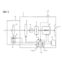
以下、図を参照して本発明を実施するための最良の形態について説明する。図1は、本発明によるデジタルカメラの一実施の形態を説明するブロック図である。図1に示すデジタルカメラはレンズ交換式のカメラであって、カメラ本体1に対して撮影レンズ3を有する交換レンズ2が着脱可能に装着されている。
Hereinafter, the best mode for carrying out the present invention will be described with reference to the drawings. FIG. 1 is a block diagram for explaining an embodiment of a digital camera according to the present invention. The digital camera shown in FIG. 1 is an interchangeable lens camera, and an
撮影レンズ3は焦点距離が可変なズームレンズであって、図示していないが焦点調節を行うためのフォーカスレンズを備えている。交換レンズ2のレンズ鏡筒内には、フォーカスレンズおよびズームレンズを駆動するためのレンズ駆動部9、および、ズームレンズやフォーカスレンズ等に関するレンズ情報が予め記憶されているROM4が設けられている。カメラ本体1には、撮影レンズにより結像された被写体像を撮像する撮像素子5が設けられている。撮像素子5には、CCD撮像素子、MOS型撮像素子などが用いられる。
The photographing
撮像素子5から出力された撮像信号は、A/D変換器6によってディジタル信号に変換された後に、メモリ7に記憶される。メモリ7に記憶された撮像データは画像処理回路10に読み込まれ、そこで種々の画像処理が施される。画像処理により得られた画像データは、メモリ7に記憶されるとともに外部記憶媒体8に記録される。また、画像処理回路10では画像データから表示用の画像が生成され、その画像はLCD表示装置11に表示される。
The imaging signal output from the
CPU12はカメラ全体の制御を総括的に管理するものであって、接続されたレリーズ操作部13からの指令によりAF制御、露出制御等が行われる。以下では、本実施の形態に関係する機能についてのみ説明する。AF演算部121では、AFエリア内の撮像信号をメモリ7より読み込み、周知のコントラスト法によりAF評価値を算出する。AF評価値は、例えば、定められたAFエリアの中で横方向または縦方向のデータを取り出し、フィルタ処理を行った後に隣接画素との差分を計算し、それらの差分を積算することにより得られる。そして、このAF評価値が大きい程、高コントラストであると判断する。 The CPU 12 comprehensively manages control of the entire camera, and AF control, exposure control, and the like are performed according to commands from the connected release operation unit 13. Only the functions related to the present embodiment will be described below. The AF calculation unit 121 reads an imaging signal in the AF area from the memory 7 and calculates an AF evaluation value by a known contrast method. The AF evaluation value is obtained, for example, by taking out data in the horizontal direction or the vertical direction in a predetermined AF area, performing a filtering process, calculating a difference with an adjacent pixel, and accumulating the differences. . And it is judged that it is so high that this AF evaluation value is large.
上述したAFエリアは、撮像範囲のどの領域の撮像信号を用いてAF評価値算出を行うかを指定するものであり、例えば、図2に示すような矩形領域のAFエリア21A〜21Eが撮影画面20上に設定される。従来、AFエリア21A〜21Eの大きさや位置は固定されていたが、本実施の形態では、後述するように合焦動作に応じて位置および大きさを変更するようにした。AFエリア設定部122は、フォーカスレンズおよび駆動量ROM4内に記憶されているレンズ情報に基づいて、AFエリア21A〜21Eの大きさや位置の設定を行う。
The AF area described above designates which area of the imaging range is used to calculate the AF evaluation value. For example, the AF areas 21A to 21E of rectangular areas as shown in FIG. 20 is set. Conventionally, the sizes and positions of the
《合焦動作の説明》
本実施の形態のデジタルカメラでは、コントラストAF方式でピント合わせが行われる。CPU12は、AF演算部121で算出されたAF評価値に基づいてレンズ駆動9を制御し、撮影レンズ3の合焦動作を行わせる。AF評価値を用いる合焦動作では、被写体にピントが合っている場合には撮像画像に最も高周波成分が多く含まれ、ピントが合っている位置から外れるほど画像に含まれる高周波成分が減って低周波成分の比率が増えて行くことを利用して、「山登りAF」と呼ばれる方式によりAFが行われる。
<Description of focusing operation>
In the digital camera of this embodiment, focusing is performed using the contrast AF method. The CPU 12 controls the lens drive 9 based on the AF evaluation value calculated by the AF calculation unit 121 and causes the photographing
図3はフォーカスレンズのレンズ位置とAF評価値との関係を示す図であり、曲線Lはフォーカスレンズ位置に対するAF評価値を表している。この曲線Lは、図2に示したAFエリア21A〜21Eのいずれか一つの領域の撮像信号に基づくものである。各AFエリア21A〜21E毎に捉えている被写体領域が異なるので、各AFエリア21A〜21E毎に曲線Lの形状は異なっている。以下では、曲線L1はAFエリア21Bに関するものとして説明する。 FIG. 3 is a diagram showing the relationship between the lens position of the focus lens and the AF evaluation value, and the curve L represents the AF evaluation value with respect to the focus lens position. This curve L is based on the imaging signal of any one of the AF areas 21A to 21E shown in FIG. Since the subject area captured for each AF area 21A to 21E is different, the shape of the curve L is different for each AF area 21A to 21E. In the following description, the curve L1 is related to the AF area 21B.
山登りAFでは、フォーカスレンズを所定量移動する毎に移動前後のAF評価値の大小を比較し、その比較結果に基づいてAF評価値が増加する方向に繰り返し移動させることにより、AF評価値が最大となるレンズ位置D0にフォーカスレンズを移動させる。合焦動作は、図1のレリーズ操作部13に設けられたレリーズボタンが半押しされることにより開始される。 In hill-climbing AF, the magnitude of the AF evaluation value before and after the movement is compared each time the focus lens is moved by a predetermined amount, and the AF evaluation value is maximized by repeatedly moving in the direction in which the AF evaluation value increases based on the comparison result. The focus lens is moved to the lens position D0. The focusing operation is started when the release button provided in the release operation unit 13 of FIG. 1 is half-pressed.
合焦動作開始時のレンズ位置が、例えば図3のD1であった場合には、フォーカスレンズはD2,D3に示すようにAF評価値のピークを通過するまで∞側へと移動される。そして、ピークを通過したならば、レンズ位置D1〜D3におけるAF評価値からレンズ位置D0を推定し、推定したレンズ位置D0へフォーカスレンズを移動することで合焦動作が完了する。 For example, when the lens position at the start of the focusing operation is D1 in FIG. 3, the focus lens is moved to the ∞ side until it passes the peak of the AF evaluation value as indicated by D2 and D3. If the peak is passed, the lens position D0 is estimated from the AF evaluation values at the lens positions D1 to D3, and the focus lens is moved to the estimated lens position D0, thereby completing the focusing operation.
《撮像面上における被写体移動の説明》
次に、撮像面上における被写体移動について説明する。図4は、フォーカス動作時における撮影レンズ3の射出瞳位置と、撮像面上における被写体像の位置との関係を説明する図である。図4において、(a)はピントが合っているときの状態を示し、(b)は前ピン状態を、(c)は後ピン状態をそれぞれ示している。
<< Explanation of subject movement on the imaging surface >>
Next, subject movement on the imaging surface will be described. FIG. 4 is a diagram for explaining the relationship between the exit pupil position of the
図4(a)に示すように、撮像素子5の撮像面5aに入射する被写体光の各撮像面位置における主光線40は、射出瞳の中心41から主光線角γで出射される。通常、撮像面5aから射出瞳までの距離PO1(以下では、射出瞳位置と称す)は有限であるため、撮像面5aの光軸J上以外の位置では主光線角γはゼロではない。そして、合焦動作の際にフォーカスレンズを移動すると、主光線角γはほとんど変化しないが射出瞳位置が変化する。
As shown in FIG. 4A, the
図4(a)に示す合焦状態では被写体像は撮像面5a上に結像され、ピントの合った被写体像が撮像される。このとき、撮像面5a上における主光線40の入射位置は、光軸Jから距離aの位置となる。図4(b)の前ピン状態では、結像位置は撮像面5aよりも撮影レンズ側(図示左側)となり、このときの主光線入射位置は光軸Jから距離bの位置となる。一方、図4(c)に示す後ピン状態では、結像位置は撮像面5aよりもカメラ背面側(図示右側)となり、このときの主光線入射位置は光軸Jから距離cの位置となる。距離a,b,cは、図4からも分かるようにb>a>cとなっている。
In the in-focus state shown in FIG. 4A, the subject image is formed on the
そして、合焦動作時にフォーカスレンズが図3のD1、D2、D3の順に移動すると、図4の(c)の状態から、(a),(b)の順に変化する。その結果、撮像面5a上における被写体の位置は、図2の矢印で示すように光軸Jの位置である画面中央から周辺方向へと放射状に移動することになる。図2において22a,22b,22cは主光線角γが同一である被写体を表しており、放射方向に同一距離だけ移動している。23は主光線角γがより大きな被写体を表しており、放射方向への移動距離はより大きくなっている。
When the focus lens moves in the order of D1, D2, and D3 in FIG. 3 during the focusing operation, the state changes from the state of FIG. 4C to the order of (a) and (b). As a result, the position of the subject on the
例えば、移動前後のAFエリア21Bに注目すると、移動前にエリア外にあった被写体22bがエリア内に入り込み、逆に、移動前にエリア内にあった被写体23はエリア外へと出てしまっている。ここで、被写体22b,23に関するフォーカスレンズレンズ位置とAF評価値との関係が、図5の曲線L1,L2のようになっていた場合を考える。D10,D11は移動前後のフォーカスレンズ位置を示している。 For example, when focusing on the AF area 21B before and after the movement, the subject 22b outside the area before the movement enters the area, and conversely, the subject 23 inside the area before the movement goes out of the area. Yes. Here, a case is considered where the relationship between the focus lens lens position and the AF evaluation value regarding the subjects 22b and 23 is as indicated by the curves L1 and L2 in FIG. D10 and D11 indicate the focus lens positions before and after the movement.
レンズ位置D10のときにはAFエリア21Bは被写体23を捉えているので、曲線L1に従って山登りAFが行われるようにフォーカスレンズを至近側のレンズ位置D11へと移動する。レンズ位置D11へ移動すると、上述したようにAFエリア21Bから被写体23が出て、被写体22bがエリア内へと入ってくる。その結果、AF評価値は曲線L1上のC1から曲線L2上のC2へと変化する。その後は、被写体22bに関する曲線L2に従って山登りAFが行われるため、フォーカスレンズは∞側へと移動され曲線L2のピークP2に合焦してしまい、ユーザがピントを合わせたいと思っていた被写体23はピンボケ状態となってしまう。 Since the AF area 21B captures the subject 23 at the lens position D10, the focus lens is moved to the closest lens position D11 so that hill-climbing AF is performed according to the curve L1. When the lens position D11 is moved, the subject 23 comes out of the AF area 21B and the subject 22b enters the area as described above. As a result, the AF evaluation value changes from C1 on the curve L1 to C2 on the curve L2. After that, hill-climbing AF is performed according to the curve L2 related to the subject 22b. Therefore, the focus lens is moved to the ∞ side and focused on the peak P2 of the curve L2, and the subject 23 that the user wanted to focus on is It will be out of focus.
《AFエリア変更の説明》
本発明では、このような不都合を避けるために合焦動作に応じてAFエリアの位置や大きさを変更するようにした。図6はAFエリア変更形態を示す図であり、(a),(b)に異なる形態を示した。図6(a)では、画面中央にあるAFエリア21Aを除く4つのAFエリア21B〜21Eをフォーカス動作に連動させて放射方向に移動させるようにした。破線は移動後のAFエリアを示している。
<Explanation of AF area change>
In the present invention, in order to avoid such an inconvenience, the position and size of the AF area are changed according to the focusing operation. FIG. 6 is a diagram showing an AF area changing mode, and (a) and (b) show different modes. In FIG. 6A, the four AF areas 21B to 21E except the AF area 21A at the center of the screen are moved in the radial direction in conjunction with the focus operation. The broken line indicates the AF area after movement.
AFエリア21Bの放射方向への移動量(大きさと向き)は、射出瞳位置の変化量(大きさと光軸方向の向き)と主光線角γとから算出することができる。図7(a)はフォーカス動作時の射出瞳位置の変化量ΔPOと被写体の移動量との関係を示したもので、PO1は撮影レンズ3の射出瞳位置を示している。この射出瞳位置PO1はレンズ鏡筒内に設けられたROM4内に予め記憶されている。CPU21は、この位置PO1をROM4から読み込みAFエリア21B〜21E毎に主光線角γ1を算出し、それをメモリ7に記憶する。ここで、主光線角γ1は、AFエリア21B〜21Eの中央位置に関する主光線角であるとする。
The amount of movement (size and direction) of the AF area 21B in the radial direction can be calculated from the amount of change in the exit pupil position (size and direction in the optical axis direction) and the principal ray angle γ. FIG. 7A shows the relationship between the change amount ΔPO of the exit pupil position during the focusing operation and the amount of movement of the subject. PO1 indicates the exit pupil position of the
フォーカス動作を行うと、例えば、破線で挟まれた範囲内で射出瞳位置が変化する。ここで、フォーカス動作によって射出瞳位置がPO1から撮影レンズ方向にΔPOだけ移動したとすると、AFエリア21Bの中央にある被写体の移動量Δx1は、Δx1=ΔPO・tanγ1で与えられる。ここでは、この移動量Δx1をAFエリア21Bの移動量とする。 When the focus operation is performed, for example, the exit pupil position changes within a range sandwiched between broken lines. Here, if the exit pupil position is moved by ΔPO in the direction of the taking lens from PO1 by the focus operation, the movement amount Δx1 of the subject at the center of the AF area 21B is given by Δx1 = ΔPO · tanγ1. Here, this movement amount Δx1 is set as the movement amount of the AF area 21B.
なお、射出瞳位置の移動量ΔPOはフォーカスレンズの移動量に応じて決まるものであり、射出瞳位置の移動量とフォーカスレンズ移動量との相関は予めROM4に記憶されている。CPU21は、その相関と実際に駆動したレンズ駆動量とに基づいて射出瞳位置移動量ΔPOを算出する。
The movement amount ΔPO of the exit pupil position is determined according to the movement amount of the focus lens, and the correlation between the movement amount of the exit pupil position and the movement amount of the focus lens is stored in the
撮影レンズ3がズームレンズの場合、ズーム動作によって射出瞳位置が変化する。図7(b)はズームレンズの場合を説明する図であり、PO1はズーム位置1の場合の射出瞳位置で、PO2はズーム位置2の場合の射出瞳位置である。ズーム位置1の場合、図7(a)の場合と同様に射出瞳位置移動量ΔPOに対してAFエリア移動量はΔx1となる。一方、ズーム位置2では主光線角はγ2(<γ1)となり、同一の射出瞳位置移動量ΔPOに対するAFエリア移動量Δx2はズーム位置1におけるAFエリア移動量Δx1よりも小さくなる。
When the photographing
CPU21は、ズーム動作が行われる度に、そのズーム位置における射出瞳位置をROM4から読み込み、主光線角γを算出してメモリ7に記憶し、その主光線角γを用いてAFエリア移動量算出する。すなわち、ズーム動作に応じて射出瞳位置移動量を調節することにより、被写体移動量に応じた適切な位置へとAFエリアを移動するようにした。
Each time the zoom operation is performed, the
一方、図6(b)に示すAFエリア変更形態では、図6(a)の場合と同様にAFエリアを放射方向に移動させるとともに、AFエリアの領域を大きくするようにした。図4の(b)や(c)からも分かるように。合焦位置状態からずれると、撮像面5a上の被写体像がぼけて主光線入射位置の周りに広がる。そのため、AFエリアを放射方向に移動させてもボケた部分がエリア外に出てしまうことがあり、その場合には被写体情報が減ることになり評価値が変化する。そこで、AFエリア領域をフォーカス動作に応じて大きくすることにより、狙っている被写体の情報量の変化を低減することができる。
On the other hand, in the AF area changing mode shown in FIG. 6B, the AF area is moved in the radial direction and the area of the AF area is enlarged as in the case of FIG. As can be seen from (b) and (c) of FIG. When deviating from the focus position, the subject image on the
上述したように、本実施の形態では、フォーカス動作に応じてAFエリアを画面の放射方向に移動させるようにしたので、AFエリアの周辺にある被写体がエリア内に入り込んだり、狙っている被写体がエリア外に外れたりすることがない。その結果、本来のピント位置と異なる位置にピントが合ってしまう偽合焦等を避けることができる。 As described above, in the present embodiment, the AF area is moved in the radial direction of the screen in accordance with the focus operation, so that a subject around the AF area enters the area or the target subject is It will not come out of the area. As a result, it is possible to avoid false focusing and the like in which the focus is different from the original focus position.
ところで、図2や図6に示したAFエリア21A〜21Eは被写体画像とともにLCD表示装置11に表示されるが、上述したAFエリア21A〜21Eの変更に連動してLCD表示装置11上のAFエリア表示の位置および大きさを変えるようにする。また、AFエリア21A〜21Eの変更は合焦動作中は常に行われるが、撮影動作が行われたならば、AFエリア21A〜21Eの設定はデフォルトの状態(初期位置、初期大きさ)にリセットされる。 The AF areas 21A to 21E shown in FIGS. 2 and 6 are displayed on the LCD display device 11 together with the subject image. However, the AF areas on the LCD display device 11 are interlocked with the change of the AF areas 21A to 21E described above. Change the position and size of the display. The AF areas 21A to 21E are always changed during the focusing operation, but if the photographing operation is performed, the settings of the AF areas 21A to 21E are reset to the default state (initial position, initial size). Is done.
なお、本発明の特徴を損なわない限り、本発明は上記実施の形態に何ら限定されるものではない。例えば、交換レンズ式のデジタルカメラに限らず、レンズ一体型のデジタルカメラにも同様に適用することができる。 Note that the present invention is not limited to the above embodiment as long as the characteristics of the present invention are not impaired. For example, the present invention can be applied to not only an interchangeable lens type digital camera but also a lens-integrated digital camera.
1:カメラ本体 2:交換レンズ
3:撮影レンズ 4:ROM
5:撮像素子 7:メモリ
10:画像処理回路 11:LDC表示装置
12:CPU 121:AF演算部
122:AFエリア設定部
1: Camera body 2: Interchangeable lens 3: Shooting lens 4: ROM
5: Image sensor 7: Memory 10: Image processing circuit 11: LDC display device 12: CPU 121: AF operation unit 122: AF area setting unit
Claims (14)
前記撮像素子の撮像範囲の少なくとも周辺に周辺AFエリアを設定するAFエリア設定手段と、
撮影レンズをその光軸方向に移動して、前記撮影レンズの複数の移動位置の各々において前記AFエリア設定手段によって設定された前記周辺AFエリア内の前記撮像信号のコントラスト情報を検出し、前記複数の移動位置毎に検出された複数のコントラスト情報に基づき合焦位置を算出する焦点検出手段と、
前記焦点検出手段によって算出された合焦位置に焦点調節する焦点調節手段と、を備え、
前記AFエリア設定手段は、前記撮影レンズの結像状態が前ピン状態になる方向に前記撮影レンズが移動したとき、前記周辺AFエリアの位置を前記撮像範囲の中心から周辺に向かう放射方向に沿って変更し、前記撮影レンズの結像状態が後ピン状態になる方向に前記撮影レンズが移動したとき、前記周辺AFエリアの位置を前記撮像範囲の周辺から中心に向かう放射方向に沿って変更することを特徴とする焦点調節装置。 An image sensor that outputs an image signal;
AF area setting means for setting a peripheral AF area at least around the imaging range of the image sensor;
The imaging lens is moved in the optical axis direction, and contrast information of the imaging signal in the peripheral AF area set by the AF area setting means is detected at each of a plurality of movement positions of the imaging lens, Focus detection means for calculating a focus position based on a plurality of contrast information detected for each movement position;
Focus adjusting means for adjusting the focus to the in-focus position calculated by the focus detecting means,
The AF area setting means moves the position of the peripheral AF area along a radial direction from the center of the imaging range toward the periphery when the imaging lens moves in a direction in which the imaging state of the imaging lens becomes a front pin state. Change the position of the peripheral AF area along the radial direction from the periphery to the center of the imaging range when the imaging lens moves in a direction in which the imaging state of the imaging lens is in the rear pin state. A focusing device characterized by that.
前記AFエリア設定手段は、前記撮影レンズの複数の移動位置に応じて、前記周辺AFエリアの位置の変更に加えて前記AFエリアの大きさを変更することを特徴とする焦点調節装置。 The focus adjustment apparatus according to claim 1,
The focus adjustment apparatus, wherein the AF area setting means changes the size of the AF area in addition to the change of the position of the peripheral AF area according to a plurality of movement positions of the photographing lens.
前記AFエリア設定手段は、前記周辺AFエリアの位置を前記撮像範囲の中心から放射方向に離れるように変更するにつれて、前記周辺AFエリアの大きさを大きくなるように変更することを特徴とする焦点調節装置。 The focusing apparatus according to claim 2, wherein
The focus is characterized in that the AF area setting means changes the size of the peripheral AF area to be larger as the position of the peripheral AF area is changed away from the center of the imaging range in the radial direction. Adjusting device.
前記撮影レンズは焦点距離を変更可能なズームレンズであって、
前記AFエリア設定手段は、前記撮影レンズの複数の移動位置と前記ズームレンズの焦点距離とに応じて前記周辺AFエリアの位置を変更することを特徴とする焦点調節装置。 In the focus adjustment apparatus according to any one of claims 1 to 3,
The photographing lens is a zoom lens capable of changing a focal length,
The focus adjustment apparatus, wherein the AF area setting means changes the position of the peripheral AF area according to a plurality of movement positions of the photographing lens and a focal length of the zoom lens.
前記AFエリア設定手段は、前記周辺AFエリアに加えて、前記撮像範囲の中央付近に中央AFエリアを設定可能であり、
前記AFエリア設定手段は、前記撮影レンズの複数の移動位置に応じて前記中央AFエリアの位置を変更しないことを特徴とする焦点調節装置。 In the focus adjustment apparatus according to any one of claims 1 to 4,
The AF area setting means can set a central AF area near the center of the imaging range in addition to the peripheral AF area,
The focus adjustment apparatus, wherein the AF area setting means does not change the position of the central AF area according to a plurality of movement positions of the photographing lens.
表示装置を更に備え、
前記表示装置は、前記AFエリア設定手段によって設定されたAFエリアを表示すると共に、前記AFエリア設定手段によって変更されたAFエリアを表示することを特徴とする焦点調節装置。 In the focus adjustment apparatus according to any one of claims 1 to 5,
A display device;
The display device displays the AF area set by the AF area setting means and also displays the AF area changed by the AF area setting means.
請求項1〜6のいずれか一項に記載の焦点調節装置と、を備えたことを特徴とするデジタルカメラ。 A photographic lens that forms a subject image on a planned imaging plane;
A digital camera comprising: the focus adjustment device according to claim 1.
前記AFエリア設定手段は、前記撮影レンズの複数の移動位置に応じて前記周辺AFエリアの位置を変更した後に、前記撮像素子による撮影動作が行われたならば、前記周辺AFエリアの位置をデフォルトの状態に戻すことを特徴とするデジタルカメラ。 The digital camera according to claim 7, wherein
The AF area setting means sets the position of the peripheral AF area as a default if a shooting operation is performed by the image sensor after changing the position of the peripheral AF area according to a plurality of movement positions of the shooting lens. A digital camera characterized by returning to the state of.
前記撮影レンズがカメラ本体に着脱可能に装着される交換レンズであることを特徴とするデジタルカメラ。 The digital camera according to claim 7 or 8,
A digital camera, wherein the photographing lens is an interchangeable lens that is detachably attached to a camera body.
撮影レンズを光軸方向の複数の位置に移動して、前記複数の位置の各々における前記AFエリア内の撮像信号のコントラストを用いて合焦位置を検出する焦点検出部と、
前記撮影レンズの光軸方向の移動を制御する制御部とを含み、
前記制御部は、前記合焦位置を検出するための前記撮影レンズの光軸方向の移動による射出瞳位置の移動方向に応じて、前記周辺AFエリアの位置を前記撮像範囲の中心に向かう放射方向または中心から遠ざかる放射方向に移動するように制御することを特徴とする焦点調節装置。 An AF area setting unit that sets a peripheral AF area at least around the imaging range of the imaging device;
A focus detection unit that moves the photographic lens to a plurality of positions in the optical axis direction and detects a focus position using the contrast of the imaging signal in the AF area at each of the plurality of positions;
A control unit that controls movement of the photographing lens in the optical axis direction;
Wherein, in accordance with the moving direction of the exit pupil position by moving in the optical axis direction of the photographing lens for detecting the focus position toward the position of the peripheral AF area at the center of the imaging range radiation A focus adjustment device that controls to move in a radial direction away from the direction or center .
前記撮影レンズは変倍レンズであって、
前記制御部は、前記変倍レンズの倍率に応じて、前記撮影レンズの移動に連動させた前記AFエリアの位置の変更量を変化させることを特徴とする焦点調節装置。 The focus adjustment apparatus according to claim 10.
The taking lens is a zoom lens,
The focus adjustment apparatus, wherein the control unit changes a change amount of the position of the AF area linked to the movement of the photographing lens according to the magnification of the zoom lens.
前記撮像範囲の中央付近に設定される中央AFエリアと、前記中央AFエリアの周辺に設定される周辺AFエリアとを有しており、
前記制御部は、前記撮影レンズの移動に連動させて前記周辺AFエリアの位置を変更するとともに、前記中央AFエリアの位置を変更しないことを特徴とする焦点調節装置。 The focusing apparatus according to claim 10 or 11,
A central AF area set near the center of the imaging range, and a peripheral AF area set around the central AF area;
The controller is configured to change the position of the peripheral AF area in conjunction with the movement of the photographing lens, and does not change the position of the central AF area.
前記制御部は、前記撮影レンズの移動に連動させて前記AFエリアの位置および大きさを変更することを特徴とする焦点調節装置。 In the focus adjustment apparatus according to any one of claims 10 to 12,
The focus adjustment apparatus, wherein the control unit changes the position and size of the AF area in conjunction with movement of the photographing lens.
Priority Applications (1)
| Application Number | Priority Date | Filing Date | Title |
|---|---|---|---|
| JP2005290990A JP5124929B2 (en) | 2005-10-04 | 2005-10-04 | Focus adjustment device and digital camera |
Applications Claiming Priority (1)
| Application Number | Priority Date | Filing Date | Title |
|---|---|---|---|
| JP2005290990A JP5124929B2 (en) | 2005-10-04 | 2005-10-04 | Focus adjustment device and digital camera |
Publications (3)
| Publication Number | Publication Date |
|---|---|
| JP2007101857A JP2007101857A (en) | 2007-04-19 |
| JP2007101857A5 JP2007101857A5 (en) | 2008-12-25 |
| JP5124929B2 true JP5124929B2 (en) | 2013-01-23 |
Family
ID=38028867
Family Applications (1)
| Application Number | Title | Priority Date | Filing Date |
|---|---|---|---|
| JP2005290990A Expired - Fee Related JP5124929B2 (en) | 2005-10-04 | 2005-10-04 | Focus adjustment device and digital camera |
Country Status (1)
| Country | Link |
|---|---|
| JP (1) | JP5124929B2 (en) |
Cited By (1)
| Publication number | Priority date | Publication date | Assignee | Title |
|---|---|---|---|---|
| US10058502B2 (en) | 2015-12-31 | 2018-08-28 | L'oreal | Nail polish compositions |
Families Citing this family (4)
| Publication number | Priority date | Publication date | Assignee | Title |
|---|---|---|---|---|
| JP2014013738A (en) * | 2012-07-05 | 2014-01-23 | Tamron Co Ltd | Illuminating device |
| JP6137840B2 (en) * | 2013-01-18 | 2017-05-31 | オリンパス株式会社 | Camera system |
| CN103257510B (en) * | 2013-04-27 | 2016-01-06 | 宁波舜宇光电信息有限公司 | A kind of fast automatic focus adjustment method |
| JP6393296B2 (en) * | 2016-08-30 | 2018-09-19 | キヤノン株式会社 | IMAGING DEVICE AND ITS CONTROL METHOD, IMAGING CONTROL DEVICE, PROGRAM, AND STORAGE MEDIUM |
Family Cites Families (6)
| Publication number | Priority date | Publication date | Assignee | Title |
|---|---|---|---|---|
| JPS6366519A (en) * | 1986-09-09 | 1988-03-25 | Matsushita Electric Ind Co Ltd | Auto-focusing device |
| JPH03149512A (en) * | 1989-11-07 | 1991-06-26 | Sony Corp | Focus control circuit |
| JPH05142467A (en) * | 1991-11-25 | 1993-06-11 | Olympus Optical Co Ltd | Focusing device for camera |
| JPH07218813A (en) * | 1994-01-31 | 1995-08-18 | Nikon Corp | Camera provided with detector for line of sight |
| JPH11252441A (en) * | 1998-03-02 | 1999-09-17 | Nikon Corp | Automatic focusing device |
| JP2002006205A (en) * | 2000-06-22 | 2002-01-09 | Canon Inc | Automatic focusing camera |
-
2005
- 2005-10-04 JP JP2005290990A patent/JP5124929B2/en not_active Expired - Fee Related
Cited By (1)
| Publication number | Priority date | Publication date | Assignee | Title |
|---|---|---|---|---|
| US10058502B2 (en) | 2015-12-31 | 2018-08-28 | L'oreal | Nail polish compositions |
Also Published As
| Publication number | Publication date |
|---|---|
| JP2007101857A (en) | 2007-04-19 |
Similar Documents
| Publication | Publication Date | Title |
|---|---|---|
| JP5653035B2 (en) | Imaging apparatus, focus detection method, and control method | |
| JP5771913B2 (en) | Focus adjustment device and camera | |
| US8711274B2 (en) | Image processing apparatus and method configured to calculate defocus amount of designated area | |
| JP2011154385A (en) | Optical apparatus | |
| JP2007086596A (en) | Camera | |
| JP2009115981A (en) | Photographing device, its control method, and program | |
| EP2007135B1 (en) | Imaging apparatus | |
| JP2006017960A (en) | Imaging method and imaging apparatus | |
| JP5366643B2 (en) | Imaging device | |
| JP2008262049A (en) | Autofocusing unit, imaging apparatus, and autofocusing method | |
| JP2010045625A (en) | Imaging apparatus | |
| JP2004264827A (en) | Method for detecting focal distance and focusing device | |
| JP2014153509A (en) | Imaging device and imaging method | |
| JP5936358B2 (en) | Image display device, image display method, imaging device and control method thereof, program, and storage medium storing the same | |
| JP2012234152A (en) | Imaging apparatus and control method thereof | |
| JP4687291B2 (en) | Focus adjustment device and imaging device | |
| JP5124929B2 (en) | Focus adjustment device and digital camera | |
| JP6300670B2 (en) | Focus adjustment apparatus, focus adjustment method and program, and imaging apparatus | |
| JP2015207021A (en) | Focus adjusting device and camera | |
| JP2007133301A (en) | Autofocus camera | |
| JP6087714B2 (en) | Imaging apparatus and control method thereof | |
| JP6501536B2 (en) | Imaging device, control method therefor, program, storage medium | |
| JP2007121780A (en) | Electronic camera and lens detachable from electronic camera | |
| JP2016156950A (en) | Automatic focus adjustment device and control method of the same | |
| JP2008191391A (en) | Focusing mechanism, and camera |
Legal Events
| Date | Code | Title | Description |
|---|---|---|---|
| A621 | Written request for application examination |
Free format text: JAPANESE INTERMEDIATE CODE: A621 Effective date: 20080930 |
|
| A521 | Request for written amendment filed |
Free format text: JAPANESE INTERMEDIATE CODE: A523 Effective date: 20081107 |
|
| RD02 | Notification of acceptance of power of attorney |
Free format text: JAPANESE INTERMEDIATE CODE: A7422 Effective date: 20081107 |
|
| A977 | Report on retrieval |
Free format text: JAPANESE INTERMEDIATE CODE: A971007 Effective date: 20110112 |
|
| A131 | Notification of reasons for refusal |
Free format text: JAPANESE INTERMEDIATE CODE: A131 Effective date: 20110118 |
|
| A131 | Notification of reasons for refusal |
Free format text: JAPANESE INTERMEDIATE CODE: A131 Effective date: 20120207 |
|
| A521 | Request for written amendment filed |
Free format text: JAPANESE INTERMEDIATE CODE: A523 Effective date: 20120409 |
|
| TRDD | Decision of grant or rejection written | ||
| A01 | Written decision to grant a patent or to grant a registration (utility model) |
Free format text: JAPANESE INTERMEDIATE CODE: A01 Effective date: 20121002 |
|
| A01 | Written decision to grant a patent or to grant a registration (utility model) |
Free format text: JAPANESE INTERMEDIATE CODE: A01 |
|
| A61 | First payment of annual fees (during grant procedure) |
Free format text: JAPANESE INTERMEDIATE CODE: A61 Effective date: 20121015 |
|
| R150 | Certificate of patent or registration of utility model |
Free format text: JAPANESE INTERMEDIATE CODE: R150 Ref document number: 5124929 Country of ref document: JP Free format text: JAPANESE INTERMEDIATE CODE: R150 |
|
| FPAY | Renewal fee payment (event date is renewal date of database) |
Free format text: PAYMENT UNTIL: 20151109 Year of fee payment: 3 |
|
| FPAY | Renewal fee payment (event date is renewal date of database) |
Free format text: PAYMENT UNTIL: 20151109 Year of fee payment: 3 |
|
| R250 | Receipt of annual fees |
Free format text: JAPANESE INTERMEDIATE CODE: R250 |
|
| R250 | Receipt of annual fees |
Free format text: JAPANESE INTERMEDIATE CODE: R250 |
|
| R250 | Receipt of annual fees |
Free format text: JAPANESE INTERMEDIATE CODE: R250 |
|
| R250 | Receipt of annual fees |
Free format text: JAPANESE INTERMEDIATE CODE: R250 |
|
| R250 | Receipt of annual fees |
Free format text: JAPANESE INTERMEDIATE CODE: R250 |
|
| LAPS | Cancellation because of no payment of annual fees |