JP5124064B2 - Transparent panel and method for producing the transparent panel - Google Patents
Transparent panel and method for producing the transparent panel Download PDFInfo
- Publication number
- JP5124064B2 JP5124064B2 JP2000579439A JP2000579439A JP5124064B2 JP 5124064 B2 JP5124064 B2 JP 5124064B2 JP 2000579439 A JP2000579439 A JP 2000579439A JP 2000579439 A JP2000579439 A JP 2000579439A JP 5124064 B2 JP5124064 B2 JP 5124064B2
- Authority
- JP
- Japan
- Prior art keywords
- coating
- band
- panel
- fade
- opaque
- Prior art date
- Legal status (The legal status is an assumption and is not a legal conclusion. Google has not performed a legal analysis and makes no representation as to the accuracy of the status listed.)
- Expired - Lifetime
Links
- 238000004519 manufacturing process Methods 0.000 title claims 2
- 238000000576 coating method Methods 0.000 claims abstract description 80
- 239000011248 coating agent Substances 0.000 claims abstract description 78
- 239000011521 glass Substances 0.000 claims abstract description 48
- 239000007787 solid Substances 0.000 claims abstract description 15
- 230000002093 peripheral effect Effects 0.000 claims description 10
- 239000000463 material Substances 0.000 claims description 9
- 238000000034 method Methods 0.000 claims description 9
- 239000011247 coating layer Substances 0.000 claims 1
- 238000005240 physical vapour deposition Methods 0.000 claims 1
- 230000007704 transition Effects 0.000 abstract description 5
- 229920002037 poly(vinyl butyral) polymer Polymers 0.000 description 7
- 229920005989 resin Polymers 0.000 description 7
- 239000011347 resin Substances 0.000 description 7
- 230000000694 effects Effects 0.000 description 3
- 239000000853 adhesive Substances 0.000 description 2
- 230000001070 adhesive effect Effects 0.000 description 2
- 230000000873 masking effect Effects 0.000 description 2
- 230000005540 biological transmission Effects 0.000 description 1
- 238000000151 deposition Methods 0.000 description 1
- 238000005566 electron beam evaporation Methods 0.000 description 1
- 238000001755 magnetron sputter deposition Methods 0.000 description 1
- 230000003287 optical effect Effects 0.000 description 1
- 230000005855 radiation Effects 0.000 description 1
- 239000000758 substrate Substances 0.000 description 1
- 238000002230 thermal chemical vapour deposition Methods 0.000 description 1
- 238000002207 thermal evaporation Methods 0.000 description 1
- 230000000007 visual effect Effects 0.000 description 1
Images


Classifications
-
- B—PERFORMING OPERATIONS; TRANSPORTING
- B32—LAYERED PRODUCTS
- B32B—LAYERED PRODUCTS, i.e. PRODUCTS BUILT-UP OF STRATA OF FLAT OR NON-FLAT, e.g. CELLULAR OR HONEYCOMB, FORM
- B32B17/00—Layered products essentially comprising sheet glass, or glass, slag, or like fibres
- B32B17/06—Layered products essentially comprising sheet glass, or glass, slag, or like fibres comprising glass as the main or only constituent of a layer, next to another layer of a specific material
- B32B17/10—Layered products essentially comprising sheet glass, or glass, slag, or like fibres comprising glass as the main or only constituent of a layer, next to another layer of a specific material of synthetic resin
- B32B17/10005—Layered products essentially comprising sheet glass, or glass, slag, or like fibres comprising glass as the main or only constituent of a layer, next to another layer of a specific material of synthetic resin laminated safety glass or glazing
- B32B17/1055—Layered products essentially comprising sheet glass, or glass, slag, or like fibres comprising glass as the main or only constituent of a layer, next to another layer of a specific material of synthetic resin laminated safety glass or glazing characterized by the resin layer, i.e. interlayer
- B32B17/10761—Layered products essentially comprising sheet glass, or glass, slag, or like fibres comprising glass as the main or only constituent of a layer, next to another layer of a specific material of synthetic resin laminated safety glass or glazing characterized by the resin layer, i.e. interlayer containing vinyl acetal
-
- B—PERFORMING OPERATIONS; TRANSPORTING
- B32—LAYERED PRODUCTS
- B32B—LAYERED PRODUCTS, i.e. PRODUCTS BUILT-UP OF STRATA OF FLAT OR NON-FLAT, e.g. CELLULAR OR HONEYCOMB, FORM
- B32B17/00—Layered products essentially comprising sheet glass, or glass, slag, or like fibres
- B32B17/06—Layered products essentially comprising sheet glass, or glass, slag, or like fibres comprising glass as the main or only constituent of a layer, next to another layer of a specific material
- B32B17/10—Layered products essentially comprising sheet glass, or glass, slag, or like fibres comprising glass as the main or only constituent of a layer, next to another layer of a specific material of synthetic resin
- B32B17/10005—Layered products essentially comprising sheet glass, or glass, slag, or like fibres comprising glass as the main or only constituent of a layer, next to another layer of a specific material of synthetic resin laminated safety glass or glazing
- B32B17/10009—Layered products essentially comprising sheet glass, or glass, slag, or like fibres comprising glass as the main or only constituent of a layer, next to another layer of a specific material of synthetic resin laminated safety glass or glazing characterized by the number, the constitution or treatment of glass sheets
- B32B17/10018—Layered products essentially comprising sheet glass, or glass, slag, or like fibres comprising glass as the main or only constituent of a layer, next to another layer of a specific material of synthetic resin laminated safety glass or glazing characterized by the number, the constitution or treatment of glass sheets comprising only one glass sheet
-
- B—PERFORMING OPERATIONS; TRANSPORTING
- B32—LAYERED PRODUCTS
- B32B—LAYERED PRODUCTS, i.e. PRODUCTS BUILT-UP OF STRATA OF FLAT OR NON-FLAT, e.g. CELLULAR OR HONEYCOMB, FORM
- B32B17/00—Layered products essentially comprising sheet glass, or glass, slag, or like fibres
- B32B17/06—Layered products essentially comprising sheet glass, or glass, slag, or like fibres comprising glass as the main or only constituent of a layer, next to another layer of a specific material
- B32B17/10—Layered products essentially comprising sheet glass, or glass, slag, or like fibres comprising glass as the main or only constituent of a layer, next to another layer of a specific material of synthetic resin
- B32B17/10005—Layered products essentially comprising sheet glass, or glass, slag, or like fibres comprising glass as the main or only constituent of a layer, next to another layer of a specific material of synthetic resin laminated safety glass or glazing
- B32B17/10009—Layered products essentially comprising sheet glass, or glass, slag, or like fibres comprising glass as the main or only constituent of a layer, next to another layer of a specific material of synthetic resin laminated safety glass or glazing characterized by the number, the constitution or treatment of glass sheets
- B32B17/10036—Layered products essentially comprising sheet glass, or glass, slag, or like fibres comprising glass as the main or only constituent of a layer, next to another layer of a specific material of synthetic resin laminated safety glass or glazing characterized by the number, the constitution or treatment of glass sheets comprising two outer glass sheets
-
- B—PERFORMING OPERATIONS; TRANSPORTING
- B32—LAYERED PRODUCTS
- B32B—LAYERED PRODUCTS, i.e. PRODUCTS BUILT-UP OF STRATA OF FLAT OR NON-FLAT, e.g. CELLULAR OR HONEYCOMB, FORM
- B32B17/00—Layered products essentially comprising sheet glass, or glass, slag, or like fibres
- B32B17/06—Layered products essentially comprising sheet glass, or glass, slag, or like fibres comprising glass as the main or only constituent of a layer, next to another layer of a specific material
- B32B17/10—Layered products essentially comprising sheet glass, or glass, slag, or like fibres comprising glass as the main or only constituent of a layer, next to another layer of a specific material of synthetic resin
- B32B17/10005—Layered products essentially comprising sheet glass, or glass, slag, or like fibres comprising glass as the main or only constituent of a layer, next to another layer of a specific material of synthetic resin laminated safety glass or glazing
- B32B17/10165—Functional features of the laminated safety glass or glazing
- B32B17/10174—Coatings of a metallic or dielectric material on a constituent layer of glass or polymer
-
- C—CHEMISTRY; METALLURGY
- C03—GLASS; MINERAL OR SLAG WOOL
- C03C—CHEMICAL COMPOSITION OF GLASSES, GLAZES OR VITREOUS ENAMELS; SURFACE TREATMENT OF GLASS; SURFACE TREATMENT OF FIBRES OR FILAMENTS MADE FROM GLASS, MINERALS OR SLAGS; JOINING GLASS TO GLASS OR OTHER MATERIALS
- C03C17/00—Surface treatment of glass, not in the form of fibres or filaments, by coating
- C03C17/34—Surface treatment of glass, not in the form of fibres or filaments, by coating with at least two coatings having different compositions
- C03C17/3411—Surface treatment of glass, not in the form of fibres or filaments, by coating with at least two coatings having different compositions with at least two coatings of inorganic materials
Landscapes
- Chemical & Material Sciences (AREA)
- Life Sciences & Earth Sciences (AREA)
- Engineering & Computer Science (AREA)
- Chemical Kinetics & Catalysis (AREA)
- General Chemical & Material Sciences (AREA)
- Geochemistry & Mineralogy (AREA)
- Materials Engineering (AREA)
- Organic Chemistry (AREA)
- Joining Of Glass To Other Materials (AREA)
- Laminated Bodies (AREA)
- Glass Compositions (AREA)
- Securing Of Glass Panes Or The Like (AREA)
Abstract
Description
【0001】
本発明は新規な透明パネルに関する。
【0002】
透明パネル、特に車両の透明板ガラス、さらに特に風防ガラスは、普通接着剤を使用して所定位置に固定される。これらのパネルは平面であっても、あるいは曲面であってもよい。該パネルは、前記パネルの全周にわたって延在する不透明バンドを具えることがあり、この目的は、前記パネルと車両との境界をマスキングすることにより風防ガラスの外観を改良し、かつ経時的に結合性を損ないかねない紫外線から接着剤を保護することにある。この不透明バンドは不明瞭化バンドと呼ばれ、一般には前記パネルの周囲に延在するべた色のバンドを含んでなる。通常、前記パネルは、前記不透明バンドの内側端から内方に延在するフェードアウトバンドをさらに具え、この場合、この不透明さは装飾的なパターンで設けられ、そのガラスの表面積の1〜99%が不透明となる。前記フェードアウトバンドは、前記べた色不透明バンドと前記透明ガラスとの間の変わり目が際立つことを避けることによりパネルの目視外観を改良する。
【0003】
最近の車両用透明パネルの共通の特徴のうち別のものとしては、ガラス上に多層透明赤外線反射および/または吸収コーティングを設けることであり、この場合、1またはそれ以上の層がIRおよび/または太陽光線を反射し、これにより、前記透明パネルを介して伝えられる熱エネルギーを減少させる。通常、これらのコーティングは前記パネルの外側端まで延在しない。この理由は、延在させた場合には、腐蝕する傾向があるからである。米国特許第5492750は、ガラスの周囲にコーティングが堆積するのを防止するためのマスクを使用して、ガラスの表面にこのようなコーティングを塗布する方法を開示している。該マスクの厚さは、前記コーティング端を強調するために望ましくないと言われているゴースト効果を前記コーティングの周囲に残す程度である。前記コーティングの先端が前記不透明バンドと重ならない場合、ガラスの前記被覆領域と非被覆領域間での反射および透過率における変化は顕著であり、ドライバの注意をそらしかねない。前記不透明バンドのべた色部分と前記コーティング端の間の重なりを確実にすることにより、この注意散漫を除去する試みは満足のいく結果をもたらさなかった。この理由は、特に、前記コーティングが前面に存在し、前記不透明バンドが背面に存在する場所から見た場合、前記ガラスの被覆領域および非被覆領域の間の変わり目は非常に目立ちかつ審美的に不快だからである。このことは、ゴースト効果が前記コーティングの周囲端に存在する場合に当てはまる。EPA 0702 423 A1は、赤外線を透過する僅かな領域の非被覆ガラス部分を有する被覆ウィンドスクリーンを開示している。この非被覆領域はより均一な外観を風防ガラスに与えるため、光を吸収するための層で覆われることが提案されている。
【0004】
本発明者らは、透明パネルの外観および光学特性を、前記コーティングの端が前記フェードアウトバンドと重なるが、前記不透明バントのべた色部分とは重ならないようにすることにより改良できることを見出した。
こうして、本発明の一観点から提供されるものは、適当な樹脂で結合した2枚またはそれ以上のガラスシートを含む積層透明パネルであって、該透明パネルの少なくとも1つの面に設けられかつパネルの全周に延在する不透明バンドと、該不透明バンドから内方に延在するフェードアウトバンドと、前記透明パネルの少なくとも1つの面に設けられた少なくとも1つの多層透明赤外線コーティングとからなり、前記不透明バンドが設けられる表面よりも最外側表面により近いガラス表面に前記コーティングが設けられ、かつ前記コーティングの外側端が前記フェードアウトバンド内に存在することを特徴とする透明パネルである。前記コーティング端の全長が前記フェードアウトバンド内に存在することが好ましい。しかし、例えばべた色印刷領域によりマスクされた雨センサが存在する場合等により、必ずしもこれが可能ではない。このような場合には、できるだけ多くのコーティング端を前記フェードアウトバンド内に位置させることが好ましい。一般には、前記コーティング端の少なくとも90%が前記フェードアウトバンド内に存在することを確実にする。
【0005】
前記透明パネルは積層パネルとする。積層パネルは適当な樹脂、典型的にはポリビニルブチラール(PVB)で結合した2枚またはそれ以上のガラスシートからなる。コーティングフィルムと不透明バンドの相対的位置が逆になる場合に有用であるけれども、本発明は、前記コーティングフィルムが前面(車両の内側から見た場合)にあり、前記不透明バンドが背面にある特別な用途を見出した。積層パネルにおいて、通常、前記不透明バンドはガラスの外側面には配置されず、最内ガラス面に適用されるのが、最も普通である。前記コーティングは前記積層体の最外パネルの内側に設けられるのが、最も普通である(これは、しばしば最外側表面を表面1とし、その後、それに続く面に連続番号を付した場合に、表面2と称される)。前記コーティング、前記不透明バンド、および前記フェードアウトバンドは、平面透明パネルに、曲面透明パネルに、または後で曲面にされる平面透明パネルに設けることができる。
【0006】
積層パネルにおいて、前記コーティングは前記樹脂層内に位置させることができる。すなわち、前記コーティングは樹脂によって取り囲まれ、ガラスには接触しない。これらのパネルはコーティングが既に配置されている樹脂を使用することにより、2枚のガラスシートを一緒に結合して構成される。前記コーティングが前記樹脂層によって取り囲まれる場合、前記コーティングを透明な高分子材料(例えばPET)上に堆積し、その後、前記積層体に組み入れることができる。この態様では、前記コーティングを組み入れた前記高分子材料は、その端が前記フェードアウトバンド内に存在するような形およびサイズに切断されるのが好ましい。積層パネルにおいて、前記フェードアウトバンドは通常、本発明のこの態様では前記積層体の表面1以外の表面に設けられる。
【0007】
前記不透明バンドのべた色区域および前記フェードアウトバンドの全幅は、5〜300mmの広範囲で変わることができるが、典型的には、10〜150mmの範囲内である。前記べた色不透明バンドの幅は、所望の外観を呈するのに充分な幅である。前記フェードアウトバンドは装飾的効果を有するようにデザインされ、かつ該バンドの幅および形は特定の外観を呈するように変えることができる。前記フェードアウトバンド内の陰影の濃度は、ガラスの表面積の1〜99%の広い範囲でべた色で覆われて変化し得る。前記フェードアウトバンド内の着色の濃度は、前記バンドの幅を横切って変わり、例えば、前記不透明バンドのべた色区域に隣接する領域では高いパーセンテージの着色表面を有し、前記フェードアウトバンドの幅を横切った着色表面では低いパーセンテージを有することにより変わってもよく、あるいは、前記濃度は前記フェードアウトバンドを横切って一定であってもよい。
【0008】
前記フェードアウトバンドの着色は、前記バンドを横切って広がるカラーの多数のドットの形態をとることができるのが便利である。これらのドットはサイズ(0.001〜10.00mm)や形(例えば、円、長方形、多角形)を変えることができる。また、前記フェードアウトバンドは、ドット以外のパターンの形態をとることもできる。例えば、前記不透明バンドに平行に延びる幅の変わる色の線である。
前記コーティングの外側端は、前記フェードアウトバンドの端と、少なくとも0.1mm、好ましくは、少なくとも0.5mmだけ重なると好ましい。前記端は通常、前記べた色不透明バンドの内側端の少なくとも0.1mm、好ましくは、少なくとも0.5mm手前で終わる。前記コーティングは好ましくは、前記フェードアウトバンドの全周縁に沿って、該バンドと重なる。
これらのコーティングは、複雑な構成であってもよい。
【0009】
前記コーティングは、例えば、マグネトロンスパッタリング、電子線蒸着、熱蒸着、化学蒸着等の、既知の技術のいずれかを使用してガラスに設けることができる。典型的には、前記コーティングが堆積される領域は前記基板をマスキングすることによりまたはコーティングした後選択された領域から前記コーティングを除去することにより制御される。使用された方法の幾つかの結果として、ガラスの被覆領域から非被覆領域への変わり目はきわだっていない場合がある。前記コーティング領域の前記端における変わり目領域は典型的に0.001〜2.0mmの幅であり、これは使用方法に依存する。前記コーティングの端をマスクで規定した場合には、より薄いマスク、たとえば、200μm未満、好ましくは、130μm未満の厚さを有するマスクを使用することにより、ゴースティングが減少するか、あるいは回避される。本発明の別の態様では、 透明パネルの少なくとも1つの面に設けられた多層透明赤外線反射コーティングと、透明パネルの外周に設けられべた色区域からなる不透明バンドと、透明パネルの表面で前記不透明バンドから内方に延在するフェードアウトバンドとを備え、適当な樹脂で結合した2枚またはそれ以上のガラスシートを含む積層透明パネルを製造する方法であって、前記方法が、前記不透明バンドを設ける表面よりも最外側表面により近いガラス表面に前記コーティングを設けること、並びに外側端が前記フェードアウトバンド内に存在するようになるように前記コーティングを塗布することを含んで構成されることを特徴とする方法を提供する。
【0010】
【実施例】
図1〜9は、それぞれ2枚のガラスシートから構成される積層透明パネルの断面図である。
図10〜13は、それぞれ2層透明パネルの断面図である。
図14は、透明パネルの平面図である。
各図において、同じ番号は同じあるいは類似の部材を示す。
図1において、前記パネルは、ポリビニルブチラール(PVB)層14によって結合された内側ガラスシート10および外側ガラスシート12から構成される。2枚のシート10と12の表面は、業界の決まり通りに表面1から表面4の符合が付けられている。不透明バンド16は表面4に設けられる。フェードアウトバンド18は表面4上でバンド16の周縁部から内側に向かって延在している。コーティング20は表面2に設けられる。コーティング20の端はバンド18の最内端と重なっている。
【0011】
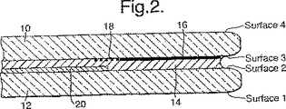
図2は、別の例を示す。この場合、不透明バンド16およびフェードアウトバンド18は前記パネルの表面3に設けられる。コーティング20は表面2に設けられる。コーティング20の端はバンド18の最内端と重なっている。
【0012】
図3は、さらに別の例を示す。この場合、不透明バンド16およびフェードアウトバンド18は前記パネルの表面4に設けられる。コーティング20は前記パネルの表面3に設けられる。
【0013】
図4は、さらに別の例を示す。この場合、不透明バンド16およびフェードアウトバンド18は前記パネルの表面2に設けられる。コーティング20は前記パネルの表面3に設けられる。
【0014】
図5は、さらに別の例を示す。この場合、不透明バンド16およびフェードアウトバンド18は前記パネルの表面2に設けられる。コーティング20は前記コーティングの最外端がバンド18の最内端と重なるように表面2に設けられる。
【0015】
図6は、さらに別の例を示す。この場合、不透明バンド16およびフェードアウトバンド18は前記パネルの表面3に設けられる。コーティング20も表面3に、前記コーティングの最外端がバンド18の最内端と重なるように設けられる。
【0016】
図7は、さらに別の例を示す。この場合、不透明バンド16およびフェードアウトバンド18は前記パネルの表面4に設けられる。コーティング20は前記パネルの表面2および表面3の間のPVB14内に存在する。
【0017】
図8は、さらに別の例を示す。この場合、不透明バンド16およびフェードアウトバンド18は前記パネルの表面3に設けられる。コーティング20は前記パネルの表面2および表面3の間のPVB14内に存在する。
【0018】
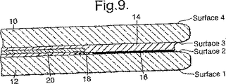
図9は、さらに別の例を示す。この場合、不透明バンド16およびフェードアウトバンド18は前記パネルの表面2に設けられる。コーティング20は前記パネルの表面2および表面3の間のPVB14内に存在する。
【0019】
図10は、2層パネルを示し、表面2(外側ガラス12の内側表面)に結合した2層用素材22を有する外側ガラス12から構成される。不透明バンド16およびフェードアウトバンド18は表面3(2層用素材22の内側表面)に設けられる。コーティング20は2層用素材22内に存在する。コーティング20の外側端はフェードアウトバンド18の最内端と重なる。
【0020】
図11は、別の2層パネルを示し、不透明バンド16およびフェードアウトバンド18は前記パネルの表面2に設けられる。コーティング20は前記パネルの表面2に設けられ、かつコーティング20の外側端はフェードアウトバンド18と重なる。
【0021】
図12は、別の2層パネルを示し、この場合、不透明バンド16およびフェードアウトバンド18は前記パネルの表面2に設けられる。コーティング20は前記2層材料22内に存在する。
【0022】
図13は、さらに別の2層パネルを示し、この場合、不透明バンド16およびフェードアウトバンド18は前記パネルの表面3に設けられる。コーティング20は前記パネルの表面2に設けられる。
【0023】
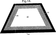
図14は、連続したべた色バンド24を有するパネルの平面図を示す。べた色バンド24は前記べた色不明瞭バンド16を表す。ドットパターン26は、前記フェードアウトバンド18を表す。コーティングの延在する周りのライン28は、前記コーティング20の最外端を表す。不透明のコーティング領域30はドットパターン26の最内端を超えて延在するコーティング領域の部分を表す。ライン28はドットパターン26の最内端を超えて外側に、ドットパターン26の周縁部の全周に延在する。
【0024】
本発明の実施例は、当業者既知の材料および技術を使用して容易に製造できる。注意点は、必要ならば、前記透明パネルをその構成部品から組み立てる場合に、前記コーティングの端がフェードアウトバンドの最内端を超えて延在することを確実にする必要があることである。
【図面の簡単な説明】
【図1】2枚のガラスシートから構成される積層透明パネルの断面図である。
【図2】2枚のガラスシートから構成される積層透明パネルの断面図である。
【図3】2枚のガラスシートから構成される積層透明パネルの断面図である。
【図4】2枚のガラスシートから構成される積層透明パネルの断面図である。
【図5】2枚のガラスシートから構成される積層透明パネルの断面図である。
【図6】2枚のガラスシートから構成される積層透明パネルの断面図である。
【図7】2枚のガラスシートから構成される積層透明パネルの断面図である。
【図8】2枚のガラスシートから構成される積層透明パネルの断面図である。
【図9】2枚のガラスシートから構成される積層透明パネルの断面図である。
【図10】2層透明パネルの断面図である。
【図11】2層透明パネルの断面図である。
【図12】2層透明パネルの断面図である。
【図13】2層透明パネルの断面図である。
【図14】透明パネルの平面図である。
【符号の説明】
16 不透明バンド
18 フェードアウトバンド
20 コーティング[0001]
The present invention relates to a novel transparent panel.
[0002]
Transparent panels, in particular transparent glass panes for vehicles, and more particularly windshields, are usually fixed in place using an adhesive. These panels may be flat or curved. The panel may comprise an opaque band extending all around the panel, the purpose of which is to improve the appearance of the windshield by masking the boundary between the panel and the vehicle, and over time. The purpose is to protect the adhesive from ultraviolet rays that may impair the bondability. This opaque band is called the obscuring band and generally comprises a solid band extending around the panel. Typically, the panel further comprises a fade-out band extending inwardly from the inner edge of the opaque band, where the opacity is provided in a decorative pattern, with 1-99% of the glass surface area It becomes opaque. The fade-out band improves the visual appearance of the panel by avoiding the noticeable transition between the solid opaque band and the transparent glass.
[0003]
Another common feature of modern vehicle transparent panels is the provision of a multilayer transparent infrared reflective and / or absorbing coating on the glass, where one or more layers are IR and / or Sunlight is reflected, thereby reducing the thermal energy transferred through the transparent panel. Usually, these coatings do not extend to the outer edge of the panel. The reason for this is that when it is extended, it tends to corrode. U.S. Pat. No. 5,492,750 discloses a method of applying such a coating to the surface of a glass using a mask to prevent the coating from depositing around the glass. The thickness of the mask is such that it leaves a ghost effect around the coating that is said to be undesirable for highlighting the coating edges. If the tip of the coating does not overlap the opaque band, the change in reflection and transmission between the coated and uncoated areas of glass is noticeable and may distract the driver. Attempts to remove this distraction by ensuring the overlap between the solid portion of the opaque band and the coating edge did not give satisfactory results. The reason for this is that the transition between the coated and uncoated areas of the glass is very noticeable and aesthetically unpleasant, especially when viewed from where the coating is on the front and the opaque band is on the back. That's why. This is true when a ghost effect is present at the peripheral edge of the coating. EPA 0702 423 A1 discloses a coated windscreen having a small area of uncoated glass that transmits infrared radiation. It has been proposed that this uncovered area is covered with a layer for absorbing light in order to give the windshield a more uniform appearance.
[0004]
The inventors have found that the appearance and optical properties of the transparent panel can be improved by ensuring that the edges of the coating overlap the fade-out band but not the solid portion of the opaque band.
Thus, what is provided from one aspect of the present invention is a laminated transparent panel comprising two or more glass sheets bonded with a suitable resin, the panel being provided on at least one surface of the transparent panel. All the obscuration band extending circumferentially made from opaque band and fade out band extending inwardly, at least one multi-layer transparent infrared coating provided on at least one surface of the transparent panel, the opaque A transparent panel characterized in that the coating is provided on a glass surface closer to the outermost surface than the surface on which the band is provided, and the outer edge of the coating is present in the fade-out band. It is preferable that the full length of the coating end exists in the fade-out band. However, this is not always possible, for example, when there is a rain sensor masked by a solid color print area. In such a case, it is preferable to locate as many coating edges as possible in the fade-out band. In general, ensure that at least 90% of the coating edges are in the fade out band.
[0005]
The transparent panel is a laminated panel. Laminate panels consist of two or more glass sheets bonded with a suitable resin, typically polyvinyl butyral (PVB). Although useful when the relative positions of the coating film and the opaque band are reversed, the present invention provides a special case where the coating film is on the front (when viewed from the inside of the vehicle) and the opaque band is on the back. Found a use. In laminated panels, the opaque band is usually most commonly applied to the innermost glass surface rather than being placed on the outer surface of the glass. It is most common for the coating to be provided on the inside of the outermost panel of the laminate (this is often the case when the outermost surface is
[0006]
In the laminated panel, the coating can be located in the resin layer. That is, the coating is surrounded by resin and does not contact the glass. By these panels to use a resin coating it has already been placed, and the two glass sheets joined together. If the coating is surrounded by the resin layer, the coating is deposited on a transparent polymeric material (e.g. PET), it can then be incorporated into the laminate. In this embodiment, the polymeric material incorporating the coating is preferably cut into a shape and size such that its ends are within the fade-out band. In the laminated panel, the fade-out band is usually provided on a surface other than the
[0007]
The solid color area of the opaque band and the overall width of the fade-out band can vary over a wide range of 5 to 300 mm, but is typically in the range of 10 to 150 mm. The solid opaque band is wide enough to provide the desired appearance. The fade-out band is designed to have a decorative effect, and the width and shape of the band can be varied to exhibit a specific appearance. The density of the shade in the fade-out band can vary with a solid color covering a wide range of 1 to 99% of the surface area of the glass. The concentration of coloration within the fade-out band varies across the width of the band, e.g. having a high percentage of colored surface in the region adjacent to the solid area of the opaque band and across the width of the fade-out band. The colored surface may vary by having a low percentage, or the concentration may be constant across the fade-out band.
[0008]
Conveniently, the fade-out band can be colored in the form of a number of dots of color that spread across the band. These dots can be changed in size (0.001 to 10.00 mm) and shape (for example, a circle, a rectangle, and a polygon). The fade-out band can take the form of a pattern other than dots. For example, a color line of varying width extending parallel to the opaque band.
The outer edge of the coating preferably overlaps the edge of the fade-out band by at least 0.1 mm, preferably at least 0.5 mm. The edge usually ends at least 0.1 mm, preferably at least 0.5 mm before the inner edge of the solid opaque band. The coating preferably overlaps the band along the entire periphery of the fade-out band.
These coatings may have a complex configuration.
[0009]
The coating can be applied to the glass using any known technique such as, for example, magnetron sputtering, electron beam evaporation, thermal evaporation, chemical vapor deposition, or the like. Typically, the area where the coating is deposited is controlled by masking the substrate or by removing the coating from selected areas after coating. As a result of some of the methods used, the transition from coated to uncoated areas of glass may not be noticeable. The transition area at the end of the coating area is typically 0.001 to 2.0 mm wide, depending on the method of use. If the edges of the coating are defined by a mask, ghosting is reduced or avoided by using a thinner mask, eg, a mask having a thickness of less than 200 μm, preferably less than 130 μm. . In another aspect of the present invention, a multilayer transparent infrared reflective coating provided on at least one surface of the transparent panel, an opaque band comprising a color area provided on the outer periphery of the transparent panel, and the opaque band on the surface of the transparent panel A laminated transparent panel comprising two or more glass sheets bonded with a suitable resin , wherein the surface is provided with the opaque band. wherein said coating providing, as well as the outer end is configured to include applying the coating so as to be present within the fade out band on the glass surface closer to the outermost surface than I will provide a.
[0010]
【Example】
1 to 9 are cross-sectional views of laminated transparent panels each composed of two glass sheets.
10 to 13 are cross-sectional views of the two-layer transparent panel.
FIG. 14 is a plan view of the transparent panel.
In each figure, the same number shows the same or similar member.
In FIG. 1, the panel is composed of an
[0011]
FIG. 2 shows another example. In this case, the
[0012]
FIG. 3 shows yet another example. In this case, the
[0013]
FIG. 4 shows another example. In this case, the
[0014]
FIG. 5 shows another example. In this case, the
[0015]
FIG. 6 shows yet another example. In this case, the
[0016]
FIG. 7 shows still another example. In this case, the
[0017]
FIG. 8 shows yet another example. In this case, the
[0018]
FIG. 9 shows yet another example. In this case, the
[0019]
FIG. 10 shows a two-layer panel consisting of an
[0020]
FIG. 11 shows another two-layer panel in which an
[0021]
FIG. 12 shows another two-layer panel, in which an
[0022]
FIG. 13 shows yet another two-layer panel, in which an
[0023]
FIG. 14 shows a plan view of a panel having a continuous solid color band 24. A solid color band 24 represents the solid color
[0024]
Embodiments of the present invention can be readily manufactured using materials and techniques known to those skilled in the art. Note that if necessary, when assembling the transparent panel from its components, it is necessary to ensure that the end of the coating extends beyond the innermost end of the fade-out band.
[Brief description of the drawings]
FIG. 1 is a cross-sectional view of a laminated transparent panel composed of two glass sheets.
FIG. 2 is a cross-sectional view of a laminated transparent panel composed of two glass sheets.
FIG. 3 is a cross-sectional view of a laminated transparent panel composed of two glass sheets.
FIG. 4 is a cross-sectional view of a laminated transparent panel composed of two glass sheets.
FIG. 5 is a cross-sectional view of a laminated transparent panel composed of two glass sheets.
FIG. 6 is a cross-sectional view of a laminated transparent panel composed of two glass sheets.
FIG. 7 is a cross-sectional view of a laminated transparent panel composed of two glass sheets.
FIG. 8 is a cross-sectional view of a laminated transparent panel composed of two glass sheets.
FIG. 9 is a cross-sectional view of a laminated transparent panel composed of two glass sheets.
FIG. 10 is a cross-sectional view of a two-layer transparent panel.
FIG. 11 is a cross-sectional view of a two-layer transparent panel.
FIG. 12 is a cross-sectional view of a two-layer transparent panel.
FIG. 13 is a cross-sectional view of a two-layer transparent panel.
FIG. 14 is a plan view of a transparent panel.
[Explanation of symbols]
16
Claims (14)
(ii)前記透明パネルの最外側表面以外のガラス表面に設けられた多層透明赤外線反射コーティング(20)を備えた透明パネルにおいて、前記不透明バンドが設けられたガラス表面よりも最外側表面により近いガラス表面に前記コーティングが設けられ、かつ前記コーティング層の外周端の少なくとも90%が前記フェードアウトバンド内に存在することを特徴とするパネル。 A transparent panel comprising a laminate comprising two or more bonded glass sheets, wherein (i) an opaque band provided on a glass surface other than the outermost surface of the transparent panel and extending over the outer periphery of the panel (16), a fade-out band (18) extending inward along the glass surface from the opaque band, and (ii) a multilayer transparent infrared reflection provided on the glass surface other than the outermost surface of the transparent panel A transparent panel comprising a coating (20), wherein the coating is provided on a glass surface that is closer to the outermost surface than the glass surface provided with the opaque band, and at least 90% of the outer peripheral edge of the coating layer is faded out A panel characterized by being in a band.
Applications Claiming Priority (3)
| Application Number | Priority Date | Filing Date | Title |
|---|---|---|---|
| EP98830664A EP0997266A1 (en) | 1998-10-30 | 1998-10-30 | Glazing panels |
| EP98830664.3 | 1998-10-30 | ||
| PCT/IB1999/001786 WO2000026023A1 (en) | 1998-10-30 | 1999-10-28 | Glazing panels |
Related Child Applications (1)
| Application Number | Title | Priority Date | Filing Date |
|---|---|---|---|
| JP2010233079A Division JP2011037709A (en) | 1998-10-30 | 2010-10-15 | Transparent panel |
Publications (2)
| Publication Number | Publication Date |
|---|---|
| JP2002528374A JP2002528374A (en) | 2002-09-03 |
| JP5124064B2 true JP5124064B2 (en) | 2013-01-23 |
Family
ID=8236867
Family Applications (2)
| Application Number | Title | Priority Date | Filing Date |
|---|---|---|---|
| JP2000579439A Expired - Lifetime JP5124064B2 (en) | 1998-10-30 | 1999-10-28 | Transparent panel and method for producing the transparent panel |
| JP2010233079A Pending JP2011037709A (en) | 1998-10-30 | 2010-10-15 | Transparent panel |
Family Applications After (1)
| Application Number | Title | Priority Date | Filing Date |
|---|---|---|---|
| JP2010233079A Pending JP2011037709A (en) | 1998-10-30 | 2010-10-15 | Transparent panel |
Country Status (9)
| Country | Link |
|---|---|
| US (1) | US6495261B1 (en) |
| EP (2) | EP0997266A1 (en) |
| JP (2) | JP5124064B2 (en) |
| AT (1) | ATE235370T1 (en) |
| AU (1) | AU6362199A (en) |
| BR (1) | BR9914935B1 (en) |
| DE (1) | DE69906366T2 (en) |
| PL (1) | PL195974B1 (en) |
| WO (1) | WO2000026023A1 (en) |
Families Citing this family (38)
| Publication number | Priority date | Publication date | Assignee | Title |
|---|---|---|---|---|
| DE19902471C2 (en) * | 1999-01-22 | 2003-07-17 | Saint Gobain Sekurit D Gmbh | laminated pane |
| BR0107590B1 (en) * | 2000-01-13 | 2010-09-21 | process for the production of laminated glass pane. | |
| JP4873814B2 (en) * | 2000-03-14 | 2012-02-08 | エージーシー フラット グラス ユーロップ エスエー | Automotive glazing panel with an electrically heatable solar control coating layer provided with a data transmission window |
| DE10022409C1 (en) * | 2000-05-09 | 2002-04-04 | Saint Gobain Sekurit D Gmbh | Process for producing a composite pane with a transparent, corrosion-protected surface coating and composite pane |
| ATE504438T1 (en) | 2003-06-12 | 2011-04-15 | Pilkington Italia Spa | METHOD FOR PRODUCING A CURVED LAMINATED GLASS PANEL |
| US20060154085A1 (en) * | 2005-01-12 | 2006-07-13 | Visteon Global Technologies, Inc. | Multilayered article having decorative frit layer for vehicle windshield and method for making same |
| GB0512077D0 (en) * | 2005-06-14 | 2005-07-20 | Pilkington Plc | Glazing |
| WO2007052600A1 (en) * | 2005-10-31 | 2007-05-10 | Nippon Sheet Glass Company, Limited | Curved glass plate with light shielding film for vehicle |
| FR2902370A1 (en) * | 2006-06-15 | 2007-12-21 | Peugeot Citroen Automobiles Sa | GLAZING LETTING THE ELECTROMAGNETIC WAVES AND VEHICLE EQUIPPED WITH SUCH GLAZING. |
| WO2008065956A1 (en) * | 2006-11-29 | 2008-06-05 | Calsonic Kansei Corporation | Headup display system of high visibility |
| WO2008069186A1 (en) | 2006-12-04 | 2008-06-12 | Asahi Glass Company, Limited | Vehicle window-use antifogging glass, production method thereof, and fixing structure thereof |
| JP2009179511A (en) * | 2008-01-30 | 2009-08-13 | Nippon Sheet Glass Co Ltd | Coated glass plate |
| DE202008017848U1 (en) * | 2008-04-10 | 2010-09-23 | Saint-Gobain Sekurit Deutschland Gmbh & Co. Kg | Transparent disc with a heatable coating and low-resistance conductive layers |
| WO2011019062A1 (en) * | 2009-08-12 | 2011-02-17 | 旭硝子株式会社 | Laminated glass for use in vehicles |
| JP2011157241A (en) * | 2010-02-03 | 2011-08-18 | Central Glass Co Ltd | Laminated glass for automobile |
| US8652576B2 (en) * | 2011-07-13 | 2014-02-18 | Vidrio Plano De Mexico, S.A. De C.V. | Method and system to form deletion windows on a glass substrate |
| JP5948785B2 (en) * | 2011-10-14 | 2016-07-06 | 旭硝子株式会社 | Laminated glass |
| US20130258436A1 (en) * | 2012-04-03 | 2013-10-03 | Sage Electrochromics, Inc. | Patterned obscuration lines for electrochromic devices |
| EP2667143B1 (en) * | 2012-05-21 | 2015-03-18 | ISOCLIMA S.p.A. | Pane construction and corresponding bullet proof window |
| DE102012012566B3 (en) * | 2012-06-23 | 2013-12-05 | Audi Ag | Composite pane for a motor vehicle and motor vehicle with such a composite pane. |
| GB201307495D0 (en) * | 2013-04-25 | 2013-06-12 | Pilkington Group Ltd | Laminated glazing |
| GB201307496D0 (en) * | 2013-04-25 | 2013-06-12 | Pilkington Group Ltd | Laminated glazing |
| EP2977202A1 (en) * | 2014-07-25 | 2016-01-27 | AGC Glass Europe | Heating glass |
| JP6536883B2 (en) * | 2015-04-22 | 2019-07-03 | アイシン精機株式会社 | Resin glass for vehicles |
| FR3046376B1 (en) * | 2015-12-30 | 2018-01-19 | Saint-Gobain Glass France | GLAZING LIGHT OF VEHICLE WITH AMOLED SCREEN |
| FR3056147B1 (en) * | 2016-09-21 | 2021-02-12 | Saint Gobain | PRINTING PROCESS ON AN EXTERNAL FACE OF A LAMINATED WINDOW |
| DE102016219288A1 (en) * | 2016-10-05 | 2018-04-05 | Bayerische Motoren Werke Aktiengesellschaft | Display element with transitional lamination of partial foils and coatings |
| JP7182838B2 (en) * | 2017-05-15 | 2022-12-05 | コーニング インコーポレイテッド | Laminates with organic ink decoration and high impact resistance |
| CO2018000469A1 (en) * | 2017-11-30 | 2018-04-30 | Agp America Sa | Automotive laminate with invisible solid edge substrate compensation layer |
| JP6938366B2 (en) * | 2017-12-28 | 2021-09-22 | 日本板硝子株式会社 | Windshield |
| RU2747406C1 (en) * | 2018-01-11 | 2021-05-04 | Сэн-Гобэн Гласс Франс | Vehicle glass, vehicle and manufacturing method |
| JP7261380B2 (en) * | 2018-07-06 | 2023-04-20 | Agc株式会社 | Glass plate for A pillar |
| US11964544B2 (en) | 2018-12-05 | 2024-04-23 | Nippon Sheet Glass Company, Limited | Automobile laminated glass |
| JP2021155001A (en) * | 2020-03-30 | 2021-10-07 | 本田技研工業株式会社 | vehicle |
| US20230382212A1 (en) * | 2022-05-27 | 2023-11-30 | Ford Motor Company | Windshield with optical windows for seal application |
| NL2032757B1 (en) * | 2022-08-16 | 2024-02-21 | Autoglas D & K B V | Automotive window laminate structure, glass sheet for use in a laminate, and method for producing an automotive window laminate structure |
| WO2024039242A1 (en) * | 2022-08-16 | 2024-02-22 | Autoglas D & K B.V. | Automotive window laminate structure, glass sheet for use in a laminate, and method for producing an automotive window laminate structure |
| CN115657311A (en) * | 2022-11-01 | 2023-01-31 | 福耀玻璃工业集团股份有限公司 | Glass capable of emitting light and displaying and vehicle |
Family Cites Families (9)
| Publication number | Priority date | Publication date | Assignee | Title |
|---|---|---|---|---|
| GB8431894D0 (en) * | 1984-12-18 | 1985-01-30 | Pilkington Brothers Plc | Laminated windows for vehicles |
| JPS6430335A (en) * | 1987-07-25 | 1989-02-01 | Sony Corp | Method and equipment for radio communication |
| US4898789A (en) * | 1988-04-04 | 1990-02-06 | Ppg Industries, Inc. | Low emissivity film for automotive heat load reduction |
| EP0358090B1 (en) * | 1988-09-01 | 1994-08-17 | Asahi Glass Company Ltd. | Window glass for an automobile |
| FR2646667B1 (en) * | 1989-05-03 | 1991-08-23 | Saint Gobain Vitrage | GLAZING WITH FILTERING STRIP AND MANUFACTURING METHOD |
| JPH05286358A (en) * | 1992-04-10 | 1993-11-02 | Asahi Glass Co Ltd | Window glass for car and its manufacture |
| DE4433051C2 (en) | 1994-09-16 | 1996-07-11 | Sekurit Saint Gobain Deutsch | Window pane made of silicate glass which is permeable to electromagnetic radiation |
| US5492750A (en) | 1994-09-26 | 1996-02-20 | Ppg Industries, Inc. | Mask for coated glass |
| DE19723701C1 (en) * | 1997-06-06 | 1999-03-11 | Flachglas Automotive Gmbh | Laminated glass pane with functional film |
-
1998
- 1998-10-30 EP EP98830664A patent/EP0997266A1/en not_active Withdrawn
-
1999
- 1999-10-28 US US09/830,404 patent/US6495261B1/en not_active Expired - Lifetime
- 1999-10-28 JP JP2000579439A patent/JP5124064B2/en not_active Expired - Lifetime
- 1999-10-28 WO PCT/IB1999/001786 patent/WO2000026023A1/en active IP Right Grant
- 1999-10-28 BR BRPI9914935-4A patent/BR9914935B1/en not_active IP Right Cessation
- 1999-10-28 AU AU63621/99A patent/AU6362199A/en not_active Abandoned
- 1999-10-28 PL PL99347540A patent/PL195974B1/en not_active IP Right Cessation
- 1999-10-28 EP EP99951048A patent/EP1135252B1/en not_active Expired - Lifetime
- 1999-10-28 DE DE69906366T patent/DE69906366T2/en not_active Expired - Lifetime
- 1999-10-28 AT AT99951048T patent/ATE235370T1/en not_active IP Right Cessation
-
2010
- 2010-10-15 JP JP2010233079A patent/JP2011037709A/en active Pending
Also Published As
| Publication number | Publication date |
|---|---|
| AU6362199A (en) | 2000-05-22 |
| JP2011037709A (en) | 2011-02-24 |
| JP2002528374A (en) | 2002-09-03 |
| DE69906366T2 (en) | 2003-12-04 |
| DE69906366D1 (en) | 2003-04-30 |
| EP0997266A1 (en) | 2000-05-03 |
| PL195974B1 (en) | 2007-11-30 |
| EP1135252B1 (en) | 2003-03-26 |
| BR9914935B1 (en) | 2009-01-13 |
| EP1135252A1 (en) | 2001-09-26 |
| ATE235370T1 (en) | 2003-04-15 |
| BR9914935A (en) | 2001-08-14 |
| WO2000026023A1 (en) | 2000-05-11 |
| PL347540A1 (en) | 2002-04-08 |
| US6495261B1 (en) | 2002-12-17 |
Similar Documents
| Publication | Publication Date | Title |
|---|---|---|
| JP5124064B2 (en) | Transparent panel and method for producing the transparent panel | |
| US3597050A (en) | Transparent article having modified radiation-transmitting properties | |
| EP0620469B1 (en) | Glass pane with reflectance reducing coating and combiner of head-up display system | |
| CA1333044C (en) | Solar control glass assembly and method of making same | |
| KR910009517B1 (en) | Comyposite solar-safety film and laminated window assembly made there from | |
| US5162145A (en) | Glazing with filtering band and process for production | |
| KR960011747B1 (en) | Solar control layered coating for glass windows | |
| EP0515848B1 (en) | Head-up display system | |
| US5641558A (en) | Window glass for an automobile | |
| US3956559A (en) | Solar control safety window | |
| US20090239017A1 (en) | Antifogging glass for a vehicle window, method for producing the same, and fixing structure for the same | |
| US4634637A (en) | Solar control film | |
| JP2016525951A (en) | Laminated glazing | |
| CN110546022A (en) | Visual impression of PDLC vehicle glass panels improved by combination of dark inner and outer stacks | |
| US20020148255A1 (en) | Method of making a vehicle window with opaque layer | |
| JP2005029083A (en) | Window glass for automobile | |
| EP4244057B1 (en) | Laminated glazing for a vehicle, particularly a motor vehicle | |
| EP1106343A1 (en) | Laminated glazing panel | |
| JP3359697B2 (en) | Automotive windows and automobiles | |
| CN112004673A (en) | Infrared reflective laminated glass panel | |
| WO1986002038A1 (en) | Solar control window film | |
| WO2023110261A1 (en) | Glazing unit for head up display | |
| CN115835960A (en) | Composite glass pane having a functional film with opaque print | |
| JP2002154177A (en) | Semi-transmittable laminated sheet | |
| JPS63136001A (en) | Production of glare preventing sheet |
Legal Events
| Date | Code | Title | Description |
|---|---|---|---|
| A621 | Written request for application examination |
Free format text: JAPANESE INTERMEDIATE CODE: A621 Effective date: 20060628 |
|
| A131 | Notification of reasons for refusal |
Free format text: JAPANESE INTERMEDIATE CODE: A131 Effective date: 20090512 |
|
| A601 | Written request for extension of time |
Free format text: JAPANESE INTERMEDIATE CODE: A601 Effective date: 20090710 |
|
| A602 | Written permission of extension of time |
Free format text: JAPANESE INTERMEDIATE CODE: A602 Effective date: 20090717 |
|
| A521 | Request for written amendment filed |
Free format text: JAPANESE INTERMEDIATE CODE: A523 Effective date: 20091112 |
|
| A02 | Decision of refusal |
Free format text: JAPANESE INTERMEDIATE CODE: A02 Effective date: 20100615 |
|
| A521 | Request for written amendment filed |
Free format text: JAPANESE INTERMEDIATE CODE: A523 Effective date: 20101015 |
|
| A911 | Transfer to examiner for re-examination before appeal (zenchi) |
Free format text: JAPANESE INTERMEDIATE CODE: A911 Effective date: 20101207 |
|
| A912 | Re-examination (zenchi) completed and case transferred to appeal board |
Free format text: JAPANESE INTERMEDIATE CODE: A912 Effective date: 20110204 |
|
| A601 | Written request for extension of time |
Free format text: JAPANESE INTERMEDIATE CODE: A601 Effective date: 20120220 |
|
| A602 | Written permission of extension of time |
Free format text: JAPANESE INTERMEDIATE CODE: A602 Effective date: 20120223 |
|
| A521 | Request for written amendment filed |
Free format text: JAPANESE INTERMEDIATE CODE: A523 Effective date: 20121002 |
|
| A01 | Written decision to grant a patent or to grant a registration (utility model) |
Free format text: JAPANESE INTERMEDIATE CODE: A01 |
|
| A61 | First payment of annual fees (during grant procedure) |
Free format text: JAPANESE INTERMEDIATE CODE: A61 Effective date: 20121029 |
|
| FPAY | Renewal fee payment (event date is renewal date of database) |
Free format text: PAYMENT UNTIL: 20151102 Year of fee payment: 3 |
|
| R150 | Certificate of patent or registration of utility model |
Free format text: JAPANESE INTERMEDIATE CODE: R150 Ref document number: 5124064 Country of ref document: JP Free format text: JAPANESE INTERMEDIATE CODE: R150 |
|
| R250 | Receipt of annual fees |
Free format text: JAPANESE INTERMEDIATE CODE: R250 |
|
| R250 | Receipt of annual fees |
Free format text: JAPANESE INTERMEDIATE CODE: R250 |
|
| R250 | Receipt of annual fees |
Free format text: JAPANESE INTERMEDIATE CODE: R250 |
|
| R250 | Receipt of annual fees |
Free format text: JAPANESE INTERMEDIATE CODE: R250 |
|
| EXPY | Cancellation because of completion of term |