JP5123246B2 - Shelf equipment - Google Patents

Shelf equipment Download PDF

Info

Publication number
JP5123246B2
JP5123246B2 JP2009107068A JP2009107068A JP5123246B2 JP 5123246 B2 JP5123246 B2 JP 5123246B2 JP 2009107068 A JP2009107068 A JP 2009107068A JP 2009107068 A JP2009107068 A JP 2009107068A JP 5123246 B2 JP5123246 B2 JP 5123246B2
Authority
JP
Japan
Prior art keywords
decorative panel
wiring
shelf
attached
cover
Prior art date
Legal status (The legal status is an assumption and is not a legal conclusion. Google has not performed a legal analysis and makes no representation as to the accuracy of the status listed.)
Expired - Fee Related
Application number
JP2009107068A
Other languages
Japanese (ja)
Other versions
JP2010258812A (en
Inventor
一範 瀬戸
弘樹 塩田
治郎 山崎
Current Assignee (The listed assignees may be inaccurate. Google has not performed a legal analysis and makes no representation or warranty as to the accuracy of the list.)
Panasonic Corp
Panasonic Holdings Corp
Original Assignee
Panasonic Corp
Matsushita Electric Industrial Co Ltd
Priority date (The priority date is an assumption and is not a legal conclusion. Google has not performed a legal analysis and makes no representation as to the accuracy of the date listed.)
Filing date
Publication date
Application filed by Panasonic Corp, Matsushita Electric Industrial Co Ltd filed Critical Panasonic Corp
Priority to JP2009107068A priority Critical patent/JP5123246B2/en
Publication of JP2010258812A publication Critical patent/JP2010258812A/en
Application granted granted Critical
Publication of JP5123246B2 publication Critical patent/JP5123246B2/en
Expired - Fee Related legal-status Critical Current
Anticipated expiration legal-status Critical

Links

Images

Description

本発明は電気機器等を載置するための棚装置に関する。   The present invention relates to a shelf device for mounting electrical equipment and the like.

液晶テレビやプラズマテレビ等の薄型テレビを壁に掛けて設置する場合、テレビの周辺機器となるDVDプレーヤーやビデオデッキ等の電気機器を設置するための棚等が必要となる。   When a flat-screen television such as a liquid crystal television or a plasma television is installed on a wall, a shelf or the like for installing an electrical device such as a DVD player or a video deck as a peripheral device of the television is required.

従来、特許文献1に示す棚装置が知られている。この棚装置は、左右一対の棚柱をビス等で壁に取り付けられる横繋ぎ材で繋ぎ、一対の棚柱に棚を突設してある。一対の棚柱の前面には棚柱の間に架け渡すように化粧パネルを取り付けてあり、この化粧パネルにより横繋ぎ材の前側が覆われている。また、化粧パネルの後方は棚に載置された電気機器とテレビを接続するための配線等を通すための配線用空所として利用され、配線用空所に配置された配線は化粧パネルにて隠せるようになっている。   Conventionally, the shelf apparatus shown in Patent Document 1 is known. In this shelf apparatus, a pair of left and right shelf columns are connected by a horizontal connecting material attached to a wall with screws or the like, and a shelf is projected from the pair of shelf columns. A decorative panel is attached to the front surface of the pair of shelf columns so as to be bridged between the shelf columns, and the front side of the lateral connecting material is covered by the decorative panel. In addition, the back of the decorative panel is used as a wiring space for passing wiring for connecting the electrical equipment placed on the shelf and the TV, and the wiring arranged in the wiring space is made up of the decorative panel. It can be hidden.

特開2006−60754号公報JP 2006-60754 A

ところで、前記配線用空所には、電気機器及びテレビの電源線が通され、通常、これらの電源線は配線用空所から引き出されて壁に設けられたコンセントに接続される。しかし、このようにすると、長い電源線が必要となり、また、多数の配線が露出して見栄えが良くない。   By the way, power lines for electrical equipment and television are passed through the wiring space, and these power lines are usually drawn out from the wiring space and connected to an outlet provided on the wall. However, in this case, a long power supply line is required, and a large number of wirings are exposed, so that the appearance is not good.

本発明は上記従来の事情に鑑みてなされたものであって、長い電源線を必要とせず、見栄え良く配線することができ、尚且つ、配線作業のしやすい棚装置を提供することを課題とする。   The present invention has been made in view of the above-described conventional circumstances, and it is an object to provide a shelf device that does not require a long power supply line, can be wired with good appearance, and is easy to perform wiring work. To do.

上記課題を解決するために本発明の棚装置は以下の構成を有する。壁2に取り付けられる支持材6と、支持材6よりも左右幅が広く支持材6に取り付けられて支持材6を室内側である前側から覆う化粧パネル7と、支持材6で支持されて化粧パネル7の前方に配置される棚8を備える。化粧パネル7の側端部から後側に向けて突設されて、化粧パネル7の支持材6より外側方に突出した部分と壁2の間に形成された配線用空所37を外側から覆うカバー部49を備える。そして、支持材6の側部にテーブルタップ57が取り付けられる取着部17が設けられ、カバー部49の前記取着部17に取り付けられて配線用空所37に配置されたテーブルタップ57に対応する部分に、前記配線用空所37を外側方に解放する作業用開口58が形成されることを特徴とする。   In order to solve the above problems, the shelf device of the present invention has the following configuration. A support member 6 attached to the wall 2, a decorative panel 7 that is wider than the support member 6 and is attached to the support member 6 so as to cover the support member 6 from the front side that is the indoor side, and a makeup supported by the support member 6. A shelf 8 is provided in front of the panel 7. A wiring space 37 formed between the portion projecting outward from the support member 6 of the decorative panel 7 and the wall 2 is projected from the side end of the decorative panel 7 toward the rear side, and is covered from the outside. A cover 49 is provided. And the attachment part 17 to which the table tap 57 is attached is provided in the side part of the support material 6, and it corresponds to the table tap 57 attached to the said attachment part 17 of the cover part 49, and arrange | positioned in the wiring space 37. A working opening 58 for releasing the wiring space 37 outward is formed in the portion to be formed.

また、前記化粧パネル7の左右方向の中央部が支持材6で支持されると共に、該化粧パネル7の支持材6より外側方に突出した両側部分と壁2の間に配線用空所37が夫々形成されることが好ましい。   Further, the center portion of the decorative panel 7 in the left-right direction is supported by the support member 6, and a wiring space 37 is provided between the both side portions protruding outward from the support member 6 of the decorative panel 7 and the wall 2. Each is preferably formed.

また、前記カバー部49を有して化粧パネル7に対して着脱自在に取り付けられる配線カバー9を備えることが好ましい。   Moreover, it is preferable to have the wiring cover 9 which has the said cover part 49 and is attached with respect to the decorative panel 7 so that attachment or detachment is possible.

本発明にあっては、取着部に取り付けられて配線用空所に配置されたテーブルタップに、棚に載置された電気機器やテレビの電源線を接続することができ、この場合、短い電源線であっても、電気機器やテレビに電力を供給することができる。また、配線用空所からは電源供給用の電線としてテーブルタップの電源線のみを引き出せばよく、多数の配線が露出せず、見栄えが良い。   In the present invention, it is possible to connect a power line of an electric device or a television set placed on a shelf to a table tap that is attached to the attachment portion and disposed in the wiring space. Even power lines can supply power to electrical equipment and televisions. Moreover, it is only necessary to draw out the power supply line of the table tap from the wiring space as a power supply electric wire, so that many wirings are not exposed and the appearance is good.

また、カバー部においてテーブルタップに対応する箇所には配線用空所を外側方に解放させる作業用開口が形成され、この作業用開口を配線用空所に外側から手を入れるための開口として利用することができる。このため取着部にテーブルタップを取り付ける作業や、取着部に取り付けられたテーブルタップに電源線を接続する作業が容易になる。   In addition, a work opening is formed in the cover portion corresponding to the table tap to release the wiring space outward, and this work opening is used as an opening for putting a hand into the wiring space from the outside. can do. For this reason, the operation | work which attaches a table tap to an attachment part, and the operation | work which connects a power supply line to the table tap attached to the attachment part become easy.

また、支持材で化粧パネルの左右方向の中央部を支持することで、化粧パネルを支持材でバランス良く支持できる。また、化粧パネルの支持材より外側方に突出した両側部分の夫々と壁との間に形成された配線用空所に配線やテーブルタップ等を露出することなく配置でき、化粧パネルと壁の間を有効に利用できる。   Moreover, by supporting the center part of the left-right direction of a decorative panel with a support material, a decorative panel can be supported with a balance with a support material. In addition, it can be placed without exposing wiring or table taps, etc. in the wiring space formed between each wall on both sides projecting outward from the support material of the decorative panel, and between the decorative panel and the wall. Can be used effectively.

また、カバー部を有する配線カバーが化粧パネルに対して着脱自在に取り付けられるものであると、化粧パネルから配線カバーを取り外すことで、配線用空所を外側方に大きく解放させて、該配線用空所に配線やテーブルタップ等を容易に配置することができる。   Further, if the wiring cover having the cover part is detachably attached to the decorative panel, the wiring cover is removed from the decorative panel, so that the wiring space is largely released outward, and the wiring cover is removed. Wiring, a table tap, etc. can be easily arranged in the void.

本発明の実施形態の一例の棚装置及びテレビを後側から見た斜視図である。It is the perspective view which looked at the shelf apparatus and television of an example of embodiment of this invention from the rear side. 同上の棚装置を設置した状態を示す前側から見た斜視図である。It is the perspective view seen from the front side which shows the state which installed the same shelf apparatus. 同上の棚装置及びテレビを下側から見た斜視図である。It is the perspective view which looked at the same shelf apparatus and television from the lower side. 同上の棚装置及びテレビを上側から見た斜視図である。It is the perspective view which looked at the same shelf apparatus and television from the upper side. 同上の棚装置の分解斜視図である。It is a disassembled perspective view of a shelf apparatus same as the above. 同上の壁に設置した棚装置の側部の水平断面図である。It is a horizontal sectional view of the side part of the shelf apparatus installed in the wall same as the above. 同上の配線カバーを示し、(a)は平面図であり、(b)は側面図である。The wiring cover same as the above is shown, (a) is a plan view, and (b) is a side view.

以下、添付図面に基づいて本発明の実施形態につき説明する。本実施形態の棚装置1は、図1乃至図4のように壁2に掛けた液晶テレビやプラズマテレビ等の薄型のテレビ3の下方に設置され、テレビ3の周辺機器となるDVDプレーヤーやビデオデッキ等の電気機器4を載置するために用いられる。なお、テレビ3はテレビ掛け具を介して壁2に取り付けられる。   Hereinafter, embodiments of the present invention will be described with reference to the accompanying drawings. The shelf apparatus 1 according to the present embodiment is installed below a thin TV 3 such as a liquid crystal TV or plasma TV hung on a wall 2 as shown in FIGS. It is used for mounting electrical equipment 4 such as a deck. The television 3 is attached to the wall 2 via a television hook.

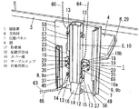
図1、図5等に示すように、棚装置1は、部屋の壁2及び床5に固着される上下に長い支持材6と、支持材6に取り付けられることで支持材6を室内側となる前側から覆う化粧パネル7と、支持材6で支持されて化粧パネル7の前方に配置される棚8と、化粧パネル7の背面の両側に着脱自在に取り付けられる配線カバー9を備えている。   As shown in FIG. 1, FIG. 5, etc., the shelf device 1 includes a support member 6 that is fixed to the wall 2 and the floor 5 of the room, and a support member 6 that is attached to the support member 6. A decorative panel 7 that covers from the front side, a shelf 8 that is supported by the support member 6 and is disposed in front of the decorative panel 7, and a wiring cover 9 that is detachably attached to both sides of the back of the decorative panel 7 are provided.

支持材6は、壁2に固着される支柱10と、支柱10の下端部に取り付けられて床5に固着される幅木よけ12とで構成される。   The support member 6 includes a column 10 fixed to the wall 2, and a baseboard shield 12 attached to the lower end of the column 10 and fixed to the floor 5.

幅木よけ12は上端部がビス等で支柱10の下端部に取り付けられ、支柱10の前部より下方に突出する。幅木よけ12の後側には左右、下方、及び後方に開口する幅木用凹所16が形成されている。また、幅木よけ12の前側には左右、上方、及び前方に開口する配線用凹所15が形成されている。   The skirting board 12 is attached at its upper end to the lower end of the column 10 with a screw or the like and protrudes downward from the front of the column 10. A baseboard recess 16 is formed on the rear side of the baseboard shield 12 so as to open to the left, right, below, and rear. In addition, a wiring recess 15 is formed on the front side of the skirting shield 12 so as to open to the left, right, upper, and front.

幅木よけ12は幅木用凹所16に壁2の下端部に設けられた幅木11の長手方向の一部を通過させた状態でビス等の固着具によりその下端部が床5に固着される。なお、幅木よけ12は床5に固着せず、床5上に載置するだけでもよい。また、本例の幅木よけ12は支柱10と別体であるが、支柱10と一体に設けてもよい。   The baseboard 12 is fixed to the floor 5 with a fixing tool such as a screw in a state where a part of the baseboard 11 provided at the lower end of the wall 2 is passed through the baseboard recess 16 in the longitudinal direction. It is fixed. Note that the skirting shield 12 may be placed on the floor 5 without being fixed to the floor 5. Further, the skirting shield 12 in this example is a separate body from the support column 10, but may be provided integrally with the support column 10.

支柱10は金属製で中空に形成され、背面部が壁2の幅木11よりも上方の室内側の面に当接される、或いは壁2の近傍に配置される。支柱10の両側面の後部の上下複数箇所には平面視L字状の取付具13の一片が取り付けられる。各取付具13の他片は背面を壁2に沿わせた状態でビス14で壁2に取り付けられる。これによって支柱10は両取付具13を介して壁2に固着される。なお、支柱10の上端部は前記テレビ掛け具に連結してもかまわない。   The support column 10 is made of metal and is formed in a hollow shape, and the back surface portion is in contact with the surface on the indoor side above the baseboard 11 of the wall 2 or is disposed in the vicinity of the wall 2. One piece of a fixture 13 having an L-shape in plan view is attached to a plurality of upper and lower portions at the rear of both side surfaces of the column 10. The other piece of each fixture 13 is attached to the wall 2 with screws 14 with the back face along the wall 2. As a result, the support column 10 is fixed to the wall 2 via both fixtures 13. In addition, the upper end part of the support | pillar 10 may be connected with the said television hanging tool.

支柱10の上部の一側面部は取着部17となっており、該取着部17には電源機器としてのテーブルタップ57がビス等で取り付けられる。支柱10の両側には平面視L字状の固定具18が取り付けられる。両固定具18は同一高さに取り付けられ、左右対称である。   One side surface portion of the upper portion of the column 10 is an attachment portion 17, and a table tap 57 as a power supply device is attached to the attachment portion 17 with a screw or the like. On both sides of the column 10, a fixture 18 having an L shape in plan view is attached. Both fixtures 18 are attached at the same height and are symmetrical.

各固定具18はL字状の一片18aを支柱10の前部両側面に沿わせてビス19で取り付けることで支柱10に固定される。各固定具18の他片18bには前後に貫通する固定具孔20が形成されている。   Each fixture 18 is fixed to the column 10 by attaching L-shaped pieces 18 a along the front side surfaces of the column 10 with screws 19. A fixture hole 20 penetrating in the front-rear direction is formed in the other piece 18 b of each fixture 18.

化粧パネル7は正面視で支持材6よりも左右幅が広い矩形状のMDFボードで形成される。化粧パネル7の中央部には前後に貫通する横長のパネル孔22が形成されている。   The decorative panel 7 is formed of a rectangular MDF board that is wider than the support member 6 in the front view. A horizontally long panel hole 22 penetrating in the front-rear direction is formed at the center of the decorative panel 7.

化粧パネル7の背面の両側端部には配線カバー9を化粧パネル7に着脱自在に取り付けるための上下に長い取着具23が取り付けられる。   At both ends of the back surface of the decorative panel 7, long attachment tools 23 for attaching the wiring cover 9 to the decorative panel 7 are attached.

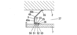
図6のように、各取着具23は樹脂製であって、具体的にはABS樹脂からなる。各取着具23は、化粧パネル7の背面にビス25で固着される固着片26と、固着片26より化粧パネル7の外側方に向けて突出する挟持片27とで構成され、挟持片27は固着片26よりも一段後方に位置する。   As shown in FIG. 6, each attachment 23 is made of resin, and specifically made of ABS resin. Each attachment 23 includes a fixing piece 26 fixed to the back surface of the decorative panel 7 with a screw 25 and a holding piece 27 protruding from the fixing piece 26 toward the outer side of the decorative panel 7. Is positioned one step behind the fixed piece 26.

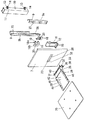
図3や図5等に示すように、棚8は、化粧パネル7から前方に突出する棚板受け28と、棚板受け28によって支持される棚板29とで構成される。   As shown in FIGS. 3 and 5, the shelf 8 includes a shelf holder 28 that protrudes forward from the decorative panel 7, and a shelf board 29 that is supported by the shelf holder 28.

棚板受け28は、棚板29を受ける受け具30と、受け具30の後端部上に取り付けられる樹脂製のキャップ31で構成される。   The shelf holder 28 includes a receiver 30 that receives the shelf 29 and a resin cap 31 that is attached to the rear end of the receiver 30.

受け具30は金属板からなり、化粧パネル7を介して両固定具18に取り付けられる取付部32と、取付部32から前方に突出する受け部33で構成されている。   The receiving tool 30 is made of a metal plate, and includes a mounting part 32 that is attached to both the fixing tools 18 via the decorative panel 7 and a receiving part 33 that protrudes forward from the mounting part 32.

取付部32の左右方向の中央部には化粧パネル7のパネル孔22と略同大同形の切欠部35(図1参照)が形成されている。   A cutout portion 35 (see FIG. 1) having substantially the same shape as the panel hole 22 of the decorative panel 7 is formed at the center portion in the left-right direction of the attachment portion 32.

棚板受け28を両固定具18に取り付けるには、化粧パネル7の背面を両固定具18の他片18bの前面に当接し、棚板受け28の取付部32を切欠部35が化粧パネル7のパネル孔22と重複するよう化粧パネル7の前面に当接する。そして、前側から取付部32、化粧パネル7、各固定具18の他片18bに順に挿通した複数のビス36により、取付部32を両固定具18に締結して、取付部32と両固定具18で化粧パネル7を挟持する。   In order to attach the shelf holders 28 to the two fixtures 18, the back of the decorative panel 7 is brought into contact with the front surfaces of the other pieces 18 b of the fixtures 18, and the attachment portions 32 of the shelf holders 28 are provided with the notches 35. It contacts the front surface of the decorative panel 7 so as to overlap with the panel hole 22. And the attachment part 32 is fastened to both the fixtures 18 by the some screw | thread 36 inserted in order from the front side to the attachment part 32, the decorative panel 7, and the other piece 18b of each fixture 18, and the attachment part 32 and both fixtures 18 holds the decorative panel 7.

つまり、棚板受け28は化粧パネル7を介して支柱10に取り付けられ、棚板受け28の取付部32、固定具18、及びビス36は化粧パネル7を支持材6に取り付けるための取付手段を兼ねている。   That is, the shelf holder 28 is attached to the column 10 via the decorative panel 7, and the attachment portion 32, the fixture 18, and the screw 36 of the shelf holder 28 are attachment means for attaching the decorative panel 7 to the support member 6. Also serves as.

このようにして取り付けられた化粧パネル7は、左右方向の中央部が支持材6で支持され、上端部が壁2に取り付けられた上方のテレビ3の下端よりもやや上方に配置され、支柱10の上端部を除く大部分を前側から覆う。なお、化粧パネル7は支柱10の全体を前側から覆うものであってもかまわない。また、化粧パネル7の下端部はビス35を用いて幅木よけ12に取り付けられるが、化粧パネル7は前記固定具18にのみ取り付けられるものであってもよい。   The decorative panel 7 attached in this way is supported by the support member 6 at the center in the left-right direction, and is disposed slightly above the lower end of the upper television 3 attached to the wall 2. The most part except the upper end of is covered from the front side. The decorative panel 7 may cover the entire support column 10 from the front side. In addition, the lower end portion of the decorative panel 7 is attached to the skirting board 12 using the screws 35, but the decorative panel 7 may be attached only to the fixture 18.

化粧パネル7は、前記左右方向の中央部を挟んだ両側部分が支持材6よりも外側方に突出し、これら突出部分と後方の壁2の間には配線やテーブルタップ57等を収容する配線用空所37(図1、図6参照)が形成される。両配線用空所37はこの間の支持材6で仕切られるが、幅木よけ12の配線用凹所15を介して連通する。   The decorative panel 7 has both side portions sandwiching the central portion in the left-right direction projecting outward from the support material 6, and between these projecting portions and the rear wall 2, wiring and table taps 57 are accommodated. A void 37 (see FIGS. 1 and 6) is formed. Both wiring spaces 37 are partitioned by the support member 6 therebetween, but communicate with each other through the wiring recess 15 of the skirting shield 12.

化粧パネル7のパネル孔22の左右方向の中央部は後方の支柱10によって塞がれる。パネル孔22の中央部を挟んだ両側部分は支柱10よりも外側方に位置して配線引出口38を構成する。各配線引出口38は対応する固定具18の固定具孔20を介して配線用空所37に連通する。   The central part in the left-right direction of the panel hole 22 of the decorative panel 7 is closed by the rear column 10. Both side portions sandwiching the center portion of the panel hole 22 are located on the outer side of the column 10 to form the wiring outlet 38. Each wiring outlet 38 communicates with the wiring space 37 via the fixture hole 20 of the corresponding fixture 18.

図5のように受け具30の受け部33は、切欠部35の両側の側縁及び下縁の夫々から前方に突出する側板部39及び底板部40と、両側板部39の上縁から外側方に突出する支持片部41とで構成されている。   As shown in FIG. 5, the receiving portion 33 of the receiving tool 30 includes a side plate portion 39 and a bottom plate portion 40 that protrude forward from the side edges and the lower edge on both sides of the cutout portion 35, and an outer side from the upper edge of the side plate portions 39. It is comprised with the support piece part 41 which protrudes in the direction.

両側板部39の下縁同士は底板部40で接続されている。受け部33内には両側板部39及び底板部40で囲まれた上方に開口する凹所42が形成されている。凹所42は切欠部35を通じてパネル孔22に連通する。   The lower edges of both side plate portions 39 are connected by a bottom plate portion 40. In the receiving portion 33, a recess 42 is formed that is surrounded by both side plate portions 39 and the bottom plate portion 40 and opens upward. The recess 42 communicates with the panel hole 22 through the notch 35.

底板部40は後下がりで傾斜し、各側板部39は底板部40の側縁に接続される下縁を斜片とした略直角三角形状をしている。底板部40の前縁や両側板部39の上縁は切欠部35の上端と略同一高さに位置している。底板部40はパネル孔22の前方に位置し、切欠部35及びこれと重複するパネル孔22を前方から覆う。   The bottom plate portion 40 is inclined downward and each side plate portion 39 has a substantially right triangle shape with a lower edge connected to the side edge of the bottom plate portion 40 as an oblique piece. The front edge of the bottom plate portion 40 and the upper edge of the side plate portions 39 are located at substantially the same height as the upper end of the notch portion 35. The bottom plate part 40 is located in front of the panel hole 22 and covers the cutout part 35 and the panel hole 22 overlapping therewith from the front.

キャップ31の両側端部は受け具30の各側板部39の上縁の後端部に取り付けられ、凹所42の後端部を上から覆う。   Both end portions of the cap 31 are attached to the rear end portions of the upper edges of the side plate portions 39 of the receiving device 30, and cover the rear end portions of the recesses 42 from above.

キャップ31の後部には横長で上下に貫通するキャップ孔43が形成されている。キャップ孔43は凹所42の後端部に連通し、該キャップ孔43と凹所42で配線通路66を構成している。   A cap hole 43 is formed in the rear portion of the cap 31 so as to extend horizontally and vertically. The cap hole 43 communicates with the rear end portion of the recess 42, and the cap hole 43 and the recess 42 constitute a wiring passage 66.

棚板29は木製で棚板受け28よりも左右幅の大きい矩形状に形成されている。棚板29は凹所42を上方から覆うように棚板受け28の両支持片部41上に載置され、ビス67を用いて取り付けられる。   The shelf plate 29 is made of wood and has a rectangular shape that is wider in width than the shelf plate receiver 28. The shelf plate 29 is placed on both support piece portions 41 of the shelf plate receiver 28 so as to cover the recess 42 from above, and is attached using screws 67.

図2に示すように、棚板29を棚板受け28に取り付けた状態では、棚板29が化粧パネル7の前方に離間して配置され、該棚板29と化粧パネル7の前面の間には隙間48が形成される。棚板29はキャップ孔43よりも前方に位置する。   As shown in FIG. 2, in a state in which the shelf plate 29 is attached to the shelf plate receiver 28, the shelf plate 29 is spaced apart from the front of the decorative panel 7, and between the shelf plate 29 and the front surface of the decorative panel 7. A gap 48 is formed. The shelf plate 29 is located in front of the cap hole 43.

隙間48は配線通路66を介してパネル孔22の両側部分で構成される各配線引出口38に連通する。   The gap 48 communicates with each wiring outlet 38 formed on both sides of the panel hole 22 through the wiring passage 66.

各配線カバー9は樹脂製であって、具体的にはABS樹脂からなる。図6及び図7に示すように、各配線カバー9は、対応する配線用空所37を外側方から覆うカバー部49と、カバー部49の前縁から化粧パネル7の内側方に向けて突出して化粧パネル7の背面に沿わせられる差込片部50とで構成されている。   Each wiring cover 9 is made of resin, and is specifically made of ABS resin. As shown in FIGS. 6 and 7, each wiring cover 9 protrudes from the front edge of the cover portion 49 toward the inner side of the decorative panel 7 so as to cover the corresponding wiring space 37 from the outer side. The insertion piece 50 is provided along the back surface of the decorative panel 7.

差込片部50には後方に突出する嵌込部51が形成されている。各配線カバー9を化粧パネル7に取り付けるには、差込片部50を対応する取着具23の挟持片27と化粧パネル7の背面との間に形成された外側方に開口する差込溝52に挿入し、該差込片部50を挟持片27と化粧パネル7で挟持する。また、嵌込部51を取着具23の挟持片27の前面に上下に亘って形成された嵌込溝部53に嵌め込む。これにより各配線カバー9は化粧パネル7に着脱自在に取り付けられる。   The insertion piece portion 50 is formed with a fitting portion 51 that protrudes rearward. In order to attach each wiring cover 9 to the decorative panel 7, an insertion groove that is formed between the sandwiching piece 27 of the corresponding attachment 23 and the back surface of the decorative panel 7 is inserted into the insertion piece 50. The insertion piece 50 is inserted between the holding piece 27 and the decorative panel 7. Further, the fitting portion 51 is fitted into a fitting groove portion 53 formed on the front surface of the holding piece 27 of the attachment tool 23 so as to extend vertically. Thereby, each wiring cover 9 is detachably attached to the decorative panel 7.

各配線カバー9a、9bの下端は床5に当接する、又は床5の近傍に配置される。各配線カバー9のカバー部49は、化粧パネル7の背面から後方に突出する前部49aと、前部49aから化粧パネル7の内側の斜め後方に向けて突出する後部49bで構成されている。   The lower ends of the wiring covers 9a and 9b are in contact with the floor 5 or are arranged in the vicinity of the floor 5. The cover portion 49 of each wiring cover 9 includes a front portion 49 a that protrudes rearward from the back surface of the decorative panel 7, and a rear portion 49 b that protrudes obliquely rearward from the front portion 49 a inside the decorative panel 7.

後部49bの先端部は他部よりも薄肉で弾性変形しやすい弾接部55となっており、弾接部55は図6のように弾接部55を弾性変形させて壁2に接触する。カバー部49の後部49bの下端部には後方及び下方に開口する幅木用切欠56が形成されており、各配線カバー9の幅木用切欠56には壁2に設けられた幅木11を左右方向に通過させる。   The front end portion of the rear portion 49b is a resilient contact portion 55 that is thinner than the other portions and easily elastically deforms, and the resilient contact portion 55 elastically deforms the resilient contact portion 55 as shown in FIG. A baseboard notch 56 that opens rearward and downward is formed at the lower end of the rear portion 49b of the cover portion 49, and the baseboard 11 provided on the wall 2 is formed in the baseboard notch 56 of each wiring cover 9. Pass in the left-right direction.

図1のように、両配線カバー9のうち、テーブルタップ57が配置される配線用空所37を塞ぐ一方の配線カバー9aのカバー部49においてテーブルタップ57に対応する上部には作業用開口58が形成される。   As shown in FIG. 1, among the wiring covers 9, a work opening 58 is formed in an upper portion corresponding to the table tap 57 in the cover portion 49 of one wiring cover 9 a that closes the wiring space 37 where the table tap 57 is disposed. Is formed.

前記作業用開口58は配線カバー9bと同一長さで左右対称形状の長尺な部材を切断して上下長さを短くすることにより形成され、テーブルタップ57に対向してテーブルタップ57の側方に位置する部分は全て開放される。なお、各取着具23の上下長さは対応する配線カバー9と略同一の長さとされるものである。また、配線カバー9aを取り付けるための取着具23も他方の取着具23と同一長さで左右対称形状の部材を切断することにより形成される。   The working opening 58 is formed by cutting a long symmetrical member having the same length as the wiring cover 9b and shortening the vertical length, and faces the table tap 57 to the side of the table tap 57. All parts located in are opened. The vertical length of each attachment 23 is substantially the same as the corresponding wiring cover 9. The attachment 23 for attaching the wiring cover 9a is also formed by cutting a symmetrical member having the same length as the other attachment 23.

棚装置1を設置するには、壁2に取付具13を用いて支持材6を取り付け、この後、支持材6に棚8及び化粧パネル7を固定具18を用いて取り付ける。このように設置された棚装置1の化粧パネル7と壁2との間には各配線用空所37が形成され、各配線用空所37には配線やテーブルタップ57が収納される。   In order to install the shelf device 1, the support member 6 is attached to the wall 2 using the fixture 13, and then the shelf 8 and the decorative panel 7 are attached to the support member 6 using the fixture 18. Each wiring space 37 is formed between the decorative panel 7 and the wall 2 of the shelf device 1 installed in this way, and wiring and a table tap 57 are accommodated in each wiring space 37.

テーブルタップ57は上下に複数のコンセントを有し、該テーブルタップ57の電源線63の端部に設けられたプラグは壁2に設けられたコンセントに接続される。テーブルタップ57は前記支柱10に設けられた取着部17にコンセントを作業用開口58側に向けた状態でビス等で取り付けられる。このように取り付けたテーブルタップ57の下端は作業用開口58の下端と同レベルあるいは上方に配置される。   The table tap 57 has a plurality of outlets at the top and bottom, and a plug provided at the end of the power line 63 of the table tap 57 is connected to an outlet provided on the wall 2. The table tap 57 is attached to the attaching portion 17 provided on the support column 10 with a screw or the like in a state where the outlet is directed to the work opening 58 side. The lower end of the table tap 57 attached in this way is arranged at the same level or above the lower end of the work opening 58.

各配線用空所37には、配線として、前記テーブルタップ57の電源線63に加えて、テレビ3と電気機器4を接続する信号線等の接続配線64、電気機器4とチューナーを接続するアンテナ線65、テレビ3の電源線60、電気機器4の電源線61等が通される。   In each wiring space 37, in addition to the power supply line 63 of the table tap 57, a connection wiring 64 such as a signal line for connecting the television 3 and the electric device 4, and an antenna for connecting the electric device 4 and the tuner as wiring. The line 65, the power line 60 of the television 3, the power line 61 of the electric equipment 4, etc. are passed.

例えばテレビ3に接続される電源線60及び接続配線64は、テレビ3のある上方から配線用空所37に導入される。このうち電源線60のプラグは配線用空所37においてテーブルタップ57のコンセントに接続される。他方、接続配線64は、配線引出口38、配線通路66、及び隙間48を通して棚8の上方に引き出され、そのコネクターが棚8上の電気機器4に接続される。   For example, the power supply line 60 and the connection wiring 64 connected to the television 3 are introduced into the wiring space 37 from above the television 3. Among these, the plug of the power line 60 is connected to the outlet of the table tap 57 in the wiring space 37. On the other hand, the connection wiring 64 is drawn out above the shelf 8 through the wiring outlet 38, the wiring passage 66, and the gap 48, and its connector is connected to the electrical device 4 on the shelf 8.

電気機器4に接続される電源線61及びアンテナ線65は、隙間48、配線通路66、及び配線引出口38を介して配線用空所37に導入される。電源線61は配線用空所37においてテーブルタップ57のコンセントに接続される。   The power supply line 61 and the antenna line 65 connected to the electric device 4 are introduced into the wiring space 37 through the gap 48, the wiring passage 66, and the wiring outlet 38. The power line 61 is connected to the outlet of the table tap 57 in the wiring space 37.

配線用空所37に導入されたアンテナ線65や、テーブルタップ57の電源線63は、配線カバー9の下端と床5とのわずかな隙間から引き出されて、壁2に設けられたチューナーやコンセントに接続される。また、配線用空所37内の配線は幅木よけ12の配線用凹所15を通して他の配線用空所37に導入できるようにもなっている。   The antenna line 65 introduced into the wiring space 37 and the power line 63 of the table tap 57 are drawn out from a slight gap between the lower end of the wiring cover 9 and the floor 5, and a tuner or an outlet provided on the wall 2. Connected to. Further, the wiring in the wiring space 37 can be introduced into another wiring space 37 through the wiring recess 15 of the skirting board 12.

以上説明した本例の棚装置1にあっては、化粧パネル7と壁2の間に形成された配線用空所37に配線やテーブルタップ57を配置し、これら配線やテーブルタップ57を化粧パネル7と両側の配線カバー9で隠すことができる。   In the shelf apparatus 1 of the present example described above, wirings and table taps 57 are arranged in a wiring space 37 formed between the decorative panel 7 and the wall 2, and these wirings and table taps 57 are connected to the decorative panel. 7 and the wiring covers 9 on both sides.

また、このように配線用空所37に配置されたテーブルタップ57には、電気機器4やテレビ3の電源線60、61を接続することができ、この場合、短い電源線60、61であっても、電気機器4やテレビ3に電力を供給することができる。また、配線用空所37からは電源供給用の電線としてテーブルタップ57の電源線63のみを引き出せばよく、多数の配線が露出せず、見栄えが良い。   In addition, the power supply lines 60 and 61 of the electric device 4 and the television 3 can be connected to the table tap 57 arranged in the wiring space 37 in this way. In this case, the short power supply lines 60 and 61 are used. However, it is possible to supply power to the electric device 4 and the television 3. Further, only the power line 63 of the table tap 57 may be drawn out from the wiring space 37 as a power supply electric wire, and many wirings are not exposed, and the appearance is good.

さらに、配線カバー9aにおいて取着部17に取り付けられたテーブルタップ57に対応する箇所には配線用空所37を外側方に解放させる作業用開口58が形成されている。この作業用開口58は配線用空所37に外側から手を入れるための開口として利用することができ、これにより、支持材6の取着部17にテーブルタップ57を取り付ける作業や、支持材6に取り付けられたテーブルタップ57に電源線60、61を接続する作業が容易になる。   Further, a work opening 58 for releasing the wiring space 37 outward is formed at a position corresponding to the table tap 57 attached to the attachment portion 17 in the wiring cover 9a. This work opening 58 can be used as an opening for putting a hand into the wiring space 37 from the outside, whereby the work for attaching the table tap 57 to the attachment portion 17 of the support material 6 or the support material 6 can be used. The work of connecting the power supply lines 60 and 61 to the table tap 57 attached to is facilitated.

また、本例では、支持材6で化粧パネル7及び棚8の左右方向の中央部を支持するので、化粧パネル7及び棚8を支持材6でバランス良く支持できる。また、化粧パネル7の支持材6より外側方に突出した両側部分の夫々と壁2との間に形成された配線用空所37に配線やテーブルタップ57等を露出することなく配置でき、化粧パネル7と壁2の間を有効に利用できる。   Moreover, in this example, since the center part of the left-right direction of the decorative panel 7 and the shelf 8 is supported by the support material 6, the decorative panel 7 and the shelf 8 can be supported by the support material 6 with good balance. Further, the wiring panel 37 can be arranged without exposing the wiring, the table tap 57 and the like in the wiring space 37 formed between the wall 2 and each of both side portions protruding outward from the support member 6 of the decorative panel 7. The space between the panel 7 and the wall 2 can be used effectively.

また、カバー部49を有する配線カバー9が化粧パネル7に対して着脱自在に取り付けられるので、化粧パネル7から配線カバー9を取り外せば、配線用空所37の上下方向の全体を外側方に解放させ、該配線用空所37に配線やテーブルタップ57等を容易に配置することができる。   Further, since the wiring cover 9 having the cover portion 49 is detachably attached to the decorative panel 7, if the wiring cover 9 is removed from the decorative panel 7, the entire vertical direction of the wiring space 37 is released outward. Thus, the wiring, the table tap 57 and the like can be easily arranged in the wiring space 37.

なお、本例では、配線カバー9aを切断して作業用開口58を形成したが、配線カバー9aのカバー部49においてテーブルタップ57に対応する箇所に切欠を設け、該切欠で作業用開口58を構成してもよい。   In this example, the wiring cover 9a is cut to form the working opening 58. However, a notch is provided at a position corresponding to the table tap 57 in the cover portion 49 of the wiring cover 9a, and the working opening 58 is formed by the notch. It may be configured.

1 棚装置
2 壁
6 支持材
7 化粧パネル
8 棚
17 取着部
37 配線用空所
49 カバー部
57 テーブルタップ
58 作業用開口
DESCRIPTION OF SYMBOLS 1 Shelf device 2 Wall 6 Support material 7 Decorative panel 8 Shelf 17 Attachment part 37 Wiring space 49 Cover part 57 Table tap 58 Work opening

Claims (3)

壁に取り付けられる支持材と、支持材よりも左右幅が広く支持材に取り付けられて支持材を室内側である前側から覆う化粧パネルと、支持材で支持されて化粧パネルの前方に配置される棚を備え、化粧パネルの側端部から後側に向けて突設されて、化粧パネルの支持材より外側方に突出した部分と壁の間に形成された配線用空所を外側から覆うカバー部を備え、支持材の側部にテーブルタップが取り付けられる取着部が設けられ、カバー部の前記取着部に取り付けられて配線用空所に配置されたテーブルタップに対応する部分に、前記配線用空所を外側方に解放する作業用開口が形成されることを特徴とする棚装置。   A support member that is attached to the wall, a decorative panel that is wider than the support member and that is attached to the support member to cover the support member from the front side that is the indoor side, and is supported by the support member and disposed in front of the decorative panel A cover provided with a shelf and projecting from the side edge of the decorative panel toward the rear side to cover the wiring space formed between the wall protruding from the decorative panel support member and the wall from the outside An attachment portion to which a table tap is attached to a side portion of the support member, and a portion corresponding to the table tap attached to the attachment portion of the cover portion and disposed in the wiring space, A shelf apparatus, characterized in that a work opening for releasing a wiring space outward is formed. 前記化粧パネルの左右方向の中央部が支持材で支持されると共に、該化粧パネルの支持材より外側方に突出した両側部分と壁の間に配線用空所が夫々形成されることを特徴とする請求項1に記載の棚装置。   The center part of the left-right direction of the decorative panel is supported by a support material, and wiring spaces are respectively formed between both side portions protruding outward from the support material of the decorative panel and the wall. The shelf apparatus according to claim 1. 前記カバー部を有して化粧パネルに対して着脱自在に取り付けられる配線カバーを備えることを特徴とする請求項1又は請求項2に記載の棚装置。   The shelf apparatus according to claim 1, further comprising a wiring cover that has the cover portion and is detachably attached to the decorative panel.
JP2009107068A 2009-04-24 2009-04-24 Shelf equipment Expired - Fee Related JP5123246B2 (en)

Priority Applications (1)

Application Number Priority Date Filing Date Title
JP2009107068A JP5123246B2 (en) 2009-04-24 2009-04-24 Shelf equipment

Applications Claiming Priority (1)

Application Number Priority Date Filing Date Title
JP2009107068A JP5123246B2 (en) 2009-04-24 2009-04-24 Shelf equipment

Publications (2)

Publication Number Publication Date
JP2010258812A JP2010258812A (en) 2010-11-11
JP5123246B2 true JP5123246B2 (en) 2013-01-23

Family

ID=43319218

Family Applications (1)

Application Number Title Priority Date Filing Date
JP2009107068A Expired - Fee Related JP5123246B2 (en) 2009-04-24 2009-04-24 Shelf equipment

Country Status (1)

Country Link
JP (1) JP5123246B2 (en)

Family Cites Families (4)

* Cited by examiner, † Cited by third party
Publication number Priority date Publication date Assignee Title
JPS5525636Y2 (en) * 1975-10-15 1980-06-20
JP2565621B2 (en) * 1992-06-23 1996-12-18 ミサワホーム株式会社 Aluminum pillar
JP2006060754A (en) * 2004-08-18 2006-03-02 Higa-Arts & Metal Inc Wall surface unit for mounting thin-shaped television
JP3133808U (en) * 2007-05-11 2007-07-26 株式会社マノーネ Storage furniture with outlet rail

Also Published As

Publication number Publication date
JP2010258812A (en) 2010-11-11

Similar Documents

Publication Publication Date Title
JP4582132B2 (en) L-shaped stand
JP2013141197A (en) Support device for display device
KR102290620B1 (en) Display apparatus
JP4535001B2 (en) Attaching structure of auxiliary wall for fixing TV
JP2010094204A (en) Desk
JP4893492B2 (en) Shelf equipment
JP5123246B2 (en) Shelf equipment
KR100630973B1 (en) Display Device
JP2009152884A (en) Desktop apparatus
JP5210237B2 (en) Shelf equipment
JP5368808B2 (en) Shelf equipment
JP5281613B2 (en) Equipment storage cabinet
JP5129761B2 (en) Shelf equipment
JP5368807B2 (en) Shelf equipment
JP7244260B2 (en) Furniture with top plate
JP7272929B2 (en) Furniture with top plate
WO2023112592A1 (en) Duct system
JP3223460U (en) TV stand
WO2023085146A1 (en) Wire duct fixture
JP6812735B2 (en) Furniture with shelves and top plate
JP2008084558A (en) Outlet box for top plate
JP5014693B2 (en) Wiring cover device and table equipped with the device
JP2912061B2 (en) Electronic device fixing structure
KR20170007570A (en) Coupled to the monitor and the cradle structure through the wing and the hook can be made for the safety of the mini USB plug
JP4598292B2 (en) Desk with wiring function

Legal Events

Date Code Title Description
A621 Written request for application examination

Free format text: JAPANESE INTERMEDIATE CODE: A621

Effective date: 20110317

A711 Notification of change in applicant

Free format text: JAPANESE INTERMEDIATE CODE: A712

Effective date: 20120113

A977 Report on retrieval

Free format text: JAPANESE INTERMEDIATE CODE: A971007

Effective date: 20120919

TRDD Decision of grant or rejection written
A01 Written decision to grant a patent or to grant a registration (utility model)

Free format text: JAPANESE INTERMEDIATE CODE: A01

Effective date: 20121002

A01 Written decision to grant a patent or to grant a registration (utility model)

Free format text: JAPANESE INTERMEDIATE CODE: A01

A61 First payment of annual fees (during grant procedure)

Free format text: JAPANESE INTERMEDIATE CODE: A61

Effective date: 20121025

FPAY Renewal fee payment (event date is renewal date of database)

Free format text: PAYMENT UNTIL: 20151102

Year of fee payment: 3

R150 Certificate of patent or registration of utility model

Free format text: JAPANESE INTERMEDIATE CODE: R150

LAPS Cancellation because of no payment of annual fees