JP5123219B2 - Marine propulsion device - Google Patents
Marine propulsion device Download PDFInfo
- Publication number
- JP5123219B2 JP5123219B2 JP2009005917A JP2009005917A JP5123219B2 JP 5123219 B2 JP5123219 B2 JP 5123219B2 JP 2009005917 A JP2009005917 A JP 2009005917A JP 2009005917 A JP2009005917 A JP 2009005917A JP 5123219 B2 JP5123219 B2 JP 5123219B2
- Authority
- JP
- Japan
- Prior art keywords
- lock
- driving force
- propulsion device
- unit
- gear
- Prior art date
- Legal status (The legal status is an assumption and is not a legal conclusion. Google has not performed a legal analysis and makes no representation as to the accuracy of the status listed.)
- Active
Links
- 230000005540 biological transmission Effects 0.000 claims description 37
- 239000011435 rock Substances 0.000 description 7
- XLYOFNOQVPJJNP-UHFFFAOYSA-N water Substances O XLYOFNOQVPJJNP-UHFFFAOYSA-N 0.000 description 6
- 238000000034 method Methods 0.000 description 5
- 230000002093 peripheral effect Effects 0.000 description 5
- 238000006243 chemical reaction Methods 0.000 description 4
- 230000008878 coupling Effects 0.000 description 2
- 238000010168 coupling process Methods 0.000 description 2
- 238000005859 coupling reaction Methods 0.000 description 2
- 230000004048 modification Effects 0.000 description 2
- 238000012986 modification Methods 0.000 description 2
- 241000755266 Kathetostoma giganteum Species 0.000 description 1
- 230000000694 effects Effects 0.000 description 1
- 230000005611 electricity Effects 0.000 description 1
- 238000000926 separation method Methods 0.000 description 1
Images


Landscapes
- Transmission Devices (AREA)
Description
この発明は、舶用推進機に関し、特に、船体に対して推進機本体を左右方向に回動させるモータを有する舶用推進機に関する。 The present invention relates to a marine propulsion device, and more particularly to a marine propulsion device having a motor that rotates a propulsion device body in the left-right direction with respect to a hull.
従来、船体に対して推進機本体を左右方向に回動させるモータを有する舶用推進機が知られている(たとえば、特許文献1参照)。上記特許文献1には、船外機(推進機本体)を回動させるための駆動力を発生させる操舵用電動モータを備えた船外機の操舵装置が開示されている。上記特許文献1による船外機の操舵装置は、ステアリングホイールが回転されるのに伴って船外機が回動するように操舵用電動モータに電気信号が送信されるとともに、送信された電気信号に基づいて、操舵用電動モータが駆動されるように構成されている。そして、船外機は、操舵用電動モータが駆動されるのに伴って左右方向に回動されるように構成されている。 2. Description of the Related Art Conventionally, a marine propulsion device having a motor that rotates a propulsion device main body in the left-right direction with respect to a hull is known (for example, see Patent Document 1). Patent Document 1 discloses an outboard motor steering apparatus that includes a steering electric motor that generates a driving force for rotating the outboard motor (propulsion device main body). The outboard motor steering apparatus according to Patent Document 1 transmits an electrical signal to the steering electric motor so that the outboard motor rotates as the steering wheel rotates, and the transmitted electrical signal. The steering electric motor is driven on the basis of the above. The outboard motor is configured to rotate in the left-right direction as the steering electric motor is driven.
しかしながら、上記特許文献1の船外機(推進機本体)の操舵装置では、航行中、水から受ける反力が常時、操舵用電動モータに付与されるため、操舵用電動モータの負担が大きくなるという問題点がある。 However, in the steering device for an outboard motor (propulsion device main body) described in Patent Document 1, a reaction force received from water is always applied to the steering electric motor during navigation, so that the burden on the steering electric motor increases. There is a problem.
この発明は、上記のような課題を解決するためになされたものであり、この発明の1つの目的は、推進機本体を回動させるための駆動力を発生させるモータの負担が大きくなることを抑制することが可能な舶用推進機を提供することである。 The present invention has been made to solve the above-described problems, and one object of the present invention is to increase the burden on the motor that generates the driving force for rotating the propulsion device body. It is providing the marine propulsion machine which can be suppressed.
この発明の一の局面による舶用推進機は、推進機本体と、船体に対して推進機本体を左右方向に回動可能に取り付けるスイベル部と、スイベル部に設けられ、推進機本体を回動させるための駆動力を発生させるモータと、モータにより発生される駆動力を推進機本体側に伝達するとともに、モータが駆動していない場合に、推進機本体が左右方向に回動しないようにロックするロック部と、ロック部よりもモータの駆動力の下流側に設けられ、モータが駆動していない場合に、推進機本体を手動で左右方向に回動させることが可能なようにロック部によるロックを無効化するロック解除機構部とを備える。 A marine propulsion device according to one aspect of the present invention is provided with a propulsion device main body, a swivel portion that attaches the propulsion device main body to the hull so as to be rotatable in the left-right direction, and the swivel portion rotates the propulsion device main body. And a motor that generates a driving force for transmitting the driving force to the propulsion device main body side, and locks the propulsion device main body from rotating in the left-right direction when the motor is not driven. Lock part and lock part by lock part so that the propeller main body can be manually rotated in the left-right direction when the motor is not driven. And a lock release mechanism unit for invalidating.
この一の局面による舶用推進機では、上記のように、モータにより発生される駆動力を推進機本体側に伝達するとともに、モータが駆動していない場合に、推進機本体が左右方向に回動しないようにロックするロック部を設けることによって、航行中、水により発生される反力が推進機本体に対して左右方向に付与される場合にも、ロック部により、操舵方向を維持するためにモータを駆動させる必要がない。これにより、推進機本体を回動させるための駆動力を発生させるモータの負担が大きくなることを抑制することができる。また、ロック部よりもモータの駆動力の下流側に、モータが駆動していない場合に、推進機本体を手動で左右方向に回動させることが可能なようにロック部によるロックを無効化するロック解除機構部を設けることによって、ロック部を設けたためにユーザが推進機本体の外面部を手で把持して左右方向に回動させることが困難である場合にも、ロック解除機構部によりロック部によるロックを無効化することにより、推進機本体を左右方向に回動することができる。 In the marine propulsion device according to this aspect, as described above, the driving force generated by the motor is transmitted to the propulsion device main body side, and the propulsion device main body rotates in the left-right direction when the motor is not driven. In order to maintain the steering direction by the lock part even when a reaction force generated by water is applied to the propeller main body in the left-right direction during navigation by providing a lock part that locks so that it does not There is no need to drive the motor. Thereby, it can suppress that the burden of the motor which generates the drive force for rotating a propeller main body becomes large. In addition, when the motor is not driven to the downstream side of the driving force of the motor from the lock unit, the lock by the lock unit is invalidated so that the propeller main body can be manually rotated in the left-right direction. By providing the lock release mechanism, even if it is difficult for the user to grip the outer surface of the propeller main body by hand and rotate it in the left-right direction, the lock release mechanism will lock By disabling the lock by the unit, the propeller main body can be rotated in the left-right direction.
上記一の局面による舶用推進機において、好ましくは、ロック解除機構部は、モータの駆動力を推進機本体に伝達する駆動力伝達経路に設けられた所定の駆動力伝達部材を含み、所定の駆動力伝達部材において伝達される駆動力を切断可能に構成されている。このように構成すれば、所定の駆動力伝達部材を用いて、ロック部によるロック力を切断することができる。これにより、駆動力伝達部材よりも下流側でロック部によるロックを無効化することができる。 In the marine propulsion device according to the aforementioned aspect, the lock release mechanism section preferably includes a predetermined driving force transmission member provided in a driving force transmission path for transmitting the driving force of the motor to the propulsion device main body, and has a predetermined driving force. The driving force transmitted by the force transmission member is configured to be cut. If comprised in this way, the locking force by a locking part can be cut | disconnected using a predetermined driving force transmission member. Thereby, the lock | rock by a lock | rock part can be nullified downstream from a driving force transmission member.
上記ロック解除機構部は所定の駆動力伝達部材を含む舶用推進機において、好ましくは、所定の駆動力伝達部材は、ロック部の下流側に設けられ、複数のギヤが噛合するギヤ部のうちの少なくとも1つのギヤを有しており、ロック解除機構部は、少なくとも1つのギヤの噛合を解除可能に構成されている。このように構成すれば、噛合する複数のギヤのうち少なくとも1つのギヤの噛合を解除することにより、容易に、ロック部によるロック力を切断することができる。 In the marine propulsion device, the unlocking mechanism portion includes a predetermined driving force transmission member. Preferably, the predetermined driving force transmission member is provided on the downstream side of the lock portion, and a plurality of gears mesh with each other. It has at least one gear, and the lock release mechanism is configured to be able to release the engagement of at least one gear. If comprised in this way, the locking force by a lock | rock part can be easily cut | disconnected by canceling | releasing engagement of at least 1 gear among several gears to mesh | engage.
上記ロック解除機構部はギヤ部を有する舶用推進機において、好ましくは、ギヤ部は、モータの駆動力が入力される入力ギヤと、モータの駆動力を下流側に出力する出力ギヤと、入力ギヤから出力ギヤに駆動力を伝達する中間ギヤとを有しており、ロック解除機構部は、中間ギヤを入力ギヤおよび出力ギヤの少なくとも一方から離間可能に構成されている。このように構成すれば、中間ギヤは、入力ギヤおよび出力ギヤと異なり、駆動力を入力側から伝達する軸部または出力側に位置する軸部を有さないので、入力ギヤおよび出力ギヤと比べて回転軸方向に移動させ易い。これにより、容易に、中間ギヤの噛合を解除することができる。 In the marine propulsion device, the unlocking mechanism portion has a gear portion. Preferably, the gear portion includes an input gear to which the driving force of the motor is input, an output gear that outputs the driving force of the motor downstream, and an input gear. And the intermediate gear that transmits the driving force to the output gear, and the lock release mechanism is configured so that the intermediate gear can be separated from at least one of the input gear and the output gear. With such a configuration, unlike the input gear and the output gear, the intermediate gear does not have a shaft portion that transmits driving force from the input side or a shaft portion that is positioned on the output side. Easy to move in the direction of the rotation axis. Thereby, the meshing of the intermediate gear can be easily released.
上記ロック解除機構部はギヤ部を有する舶用推進機において、好ましくは、ロック解除機構部は、スイベル部の外側に設けられ、ユーザがスイベル部の外側から操作することによって、複数のギヤのうち少なくとも1つのギヤの噛合を解除可能な操作部を含む。このように構成すれば、ユーザがスイベル部の外側から操作部を操作することにより、容易に、複数のギヤのうち少なくとも1つのギヤの噛合を解除することができる。 In the marine propulsion device having the gear release portion, the lock release mechanism portion is preferably provided on the outside of the swivel portion, and the user operates from the outside of the swivel portion so that at least one of the plurality of gears. An operation unit capable of releasing the meshing of one gear is included. If comprised in this way, a user can cancel | release mesh | engagement of at least 1 gear among several gears easily by operating an operation part from the outer side of a swivel part.
上記ロック解除機構部は操作部を含む舶用推進機において、好ましくは、操作部は、ユーザが直接的に操作可能な取っ手部を有する。このように構成すれば、特別な工具などを使用せずに操作部を操作することができる。 In the marine propulsion device including the operation unit, the lock release mechanism unit preferably has a handle unit that can be directly operated by the user. If comprised in this way, an operation part can be operated, without using a special tool etc.
上記ロック解除機構部は操作部を含む舶用推進機において、好ましくは、操作部は、スイベル部に係合するネジ部を有しており、ネジ部がユーザにより回転されることにより、複数のギヤのうち少なくとも1つのギヤを噛合方向、または、噛合解除方向に移動させるように構成されている。このように構成すれば、ネジ部を回転することにより、容易に、ギヤの噛合を解除することができるとともに、噛合が解除されたギヤを再度噛合することができる。 In the marine propulsion device including the operation part, the unlocking mechanism part preferably has a screw part that engages with the swivel part, and the screw part is rotated by the user, so that a plurality of gears are provided. Of these, at least one gear is configured to move in the meshing direction or the meshing release direction. If comprised in this way, it can cancel | release mesh | engagement of a gear easily by rotating a screw part, and can mesh | engage the gear which mesh | engaged was cancelled | released again.
上記一の局面による舶用推進機において、好ましくは、ロック解除機構部の下流側に設けられ、回転されるのに伴って推進機本体を回動させる推進機回動機構と、ロック解除機構部がロック部のロックを無効化している場合に、推進機回動機構を手動で回転させる手動操舵部とをさらに備える。このように構成すれば、推進機回動機構を回転させることにより、推進機本体を回動させることができるので、ユーザが推進機本体の外面部を手で把持して左右方向に回動させる場合と比べて、より容易に、推進機本体を左右方向に回動することができる。 In the marine propulsion device according to the above aspect, the propulsion device rotation mechanism that is provided on the downstream side of the unlocking mechanism portion and rotates the propulsion device body as it is rotated, and the unlocking mechanism portion are provided. And a manual steering unit that manually rotates the propulsion unit rotation mechanism when the lock of the lock unit is invalidated. If comprised in this way, since a propulsion device main body can be rotated by rotating a propulsion device rotation mechanism, a user will grasp the outer surface part of a propulsion device main body by hand, and will rotate in the left-right direction. Compared to the case, the propeller main body can be rotated in the left-right direction more easily.
上記推進機回動機構を手動で回転させる手動操舵部を備える舶用推進機において、好ましくは、手動操舵部は、推進機回動機構の長手方向の端部近傍に設けられ、ユーザが所定の工具を使用することにより直接的に推進機回動機構を回転させることが可能なように構成されている。このように構成すれば、所定の工具により、容易に、推進機回動機構を回転させることができる。 In the marine propulsion device provided with the manual steering unit for manually rotating the propulsion device rotating mechanism, preferably, the manual steering unit is provided in the vicinity of an end portion in the longitudinal direction of the propulsion device rotating mechanism, and a user uses a predetermined tool. The propulsion unit rotating mechanism can be directly rotated by using. If comprised in this way, a propeller rotation mechanism can be easily rotated with a predetermined tool.
この場合において、好ましくは、スイベル部は、手動操舵部に対応する部分に所定の工具を挿入可能な開口部を有し、スイベル部の開口部を塞ぐ着脱可能な蓋部材をさらに備える。このように構成すれば、スイベル部の外部から開口部を介して、容易に、手動操舵部に工具を係合させることができる。 In this case, preferably, the swivel part has an opening part into which a predetermined tool can be inserted in a part corresponding to the manual steering part, and further includes a detachable lid member that closes the opening part of the swivel part. If comprised in this way, a tool can be easily engaged with a manual steering part from the exterior of a swivel part via an opening part.
上記推進機回動機構を手動で回転させる手動操舵部を備える舶用推進機において、好ましくは、前記推進機回動機構は、ボールネジである。このように構成すれば、推進機本体を高精度で左右方向に回動することができる。 In a marine propulsion device including a manual steering unit that manually rotates the propulsion device rotation mechanism, preferably, the propulsion device rotation mechanism is a ball screw. If comprised in this way, a propeller main body can be rotated to the left-right direction with high precision.
上記ロック解除機構部は所定の駆動力伝達部材を含む舶用推進機において、好ましくは、モータが駆動するのに伴って推進機本体を回動するスイベル軸と、スイベル軸と推進機本体とを連結する連結部材とをさらに備え、ロック解除機構部の所定の駆動力伝達部材は、スイベル軸が回動するのに伴って連結部材が回動されるようにスイベル軸と連結部材とを係合可能なピン部材を有しており、ロック部によるロックを無効化する際に、連結部材とスイベル軸とを係合するピン部材を取り外しすることが可能なように構成されている。このように構成すれば、連結部材とスイベル軸とを係合するピン部材を取り外すことにより、容易に、ロック部によるロックを無効化することができる。 In the marine propulsion device including the predetermined driving force transmission member, the lock release mechanism section preferably connects the swivel shaft that rotates the propulsion device body as the motor is driven, and the swivel shaft and the propulsion device main body. And a predetermined driving force transmission member of the unlocking mechanism portion can engage the swivel shaft and the connecting member so that the connecting member is rotated as the swivel shaft is rotated. When the lock by the lock portion is invalidated, the pin member that engages the connecting member and the swivel shaft can be removed. If comprised in this way, the lock | rock by a lock part can be easily nullified by removing the pin member which engages a connection member and a swivel axis.
上記ロック解除機構部は所定の駆動力伝達部材を含む舶用推進機において、好ましくは、所定の駆動力伝達部材は、ロック部の下流側に着脱可能に係合するプーリと、プーリと噛合するとともに、下流側に駆動力を伝達するベルトとを有しており、ロック解除機構部は、プーリをロック部の下流側から離間することが可能なように構成されている。このように構成すれば、プーリをロック部の下流側から離間することにより、容易に、ロック部によるロックを無効化することができる。 In the marine propulsion device, the unlocking mechanism portion includes a predetermined driving force transmission member. Preferably, the predetermined driving force transmission member meshes with a pulley that is detachably engaged with a downstream side of the lock portion. And a belt for transmitting a driving force to the downstream side, and the lock release mechanism portion is configured to be able to separate the pulley from the downstream side of the lock portion. If comprised in this way, the lock | rock by a lock part can be easily nullified by separating a pulley from the downstream of a lock part.
上記ロック解除機構部は所定の駆動力伝達部材を含む舶用推進機において、好ましくは、所定の駆動力伝達部材は、ロック部の下流側に着脱可能に係合するスプロケットと、スプロケットと噛合するとともに、下流側に駆動力を伝達するチェーンとを有しており、ロック解除機構部は、スプロケットをロック部の下流側から離間することが可能なように構成されている。このように構成すれば、スプロケットをロック部の下流側から離間することにより、容易に、ロック部によるロックを無効化することができる。 In the marine propulsion device, the unlocking mechanism portion includes a predetermined driving force transmission member. Preferably, the predetermined driving force transmission member meshes with the sprocket, which is detachably engaged with the downstream side of the lock portion. The lock release mechanism portion is configured to be able to separate the sprocket from the downstream side of the lock portion. If comprised in this way, the lock | rock by a lock part can be easily invalidated by separating a sprocket from the downstream of a lock part.
以下、本発明を具体化した実施形態を図面に基づいて説明する。 DESCRIPTION OF THE PREFERRED EMBODIMENTS Embodiments embodying the present invention will be described below with reference to the drawings.
(第1実施形態)
図中、FWDは、船舶の前進方向を示している。まず、図1〜図7を参照して、本発明の第1実施形態による船舶1に搭載された船外機3の構成について説明する。
(First embodiment)
In the figure, FWD indicates the forward direction of the ship. First, with reference to FIGS. 1-7, the structure of the outboard motor 3 mounted in the ship 1 by 1st Embodiment of this invention is demonstrated.
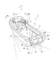
第1実施形態による船舶1には、図1に示すように、水面に浮かべられる船体2と、船体2の後部に取り付けられた船体2を推進するための2機の船外機3と、船体2を操舵するための操舵部4と、操舵部4の近傍に配置され、船体2を前進または後進させる操作を行うためのコントロールレバー部5とが設けられている。なお、船外機3は、本発明の「舶用推進機」の一例である。また、船外機3と、操舵部4およびコントロールレバー部5とは、それぞれ、共通LANケーブル6により電気的に接続されている。具体的には、共通LANケーブル6は、ユーザが操舵部4を回転した際の電気信号を船外機3のスイベルブラケット31内のドライバ7(図5参照)に伝達する機能を有しているとともに、ユーザがコントロールレバー部5を回動した際の電気信号を船外機3の後述する船外機本体30内のECU303に伝達する機能を有する。なお、船外機3は、舵を有しておらず、船外機3自体で舵を切る構造になっている。すなわち、後述する船外機3の船外機本体30を左右方向に回動させることにより後述するプロペラ304(図2参照)の向きを変えることによって、そのプロペラ304の推力で船体2が方向を変えられるように構成されている。
As shown in FIG. 1, the ship 1 according to the first embodiment includes a
船外機3は、図2に示すように、船外機本体30と、スイベル軸310を中心に船外機本体30と相対的に回動可能に取り付けられたスイベルブラケット31と、チルト軸320を中心にスイベルブラケット31と相対的に回動可能に取り付けられたチルトブラケット32とを含んでいる。なお、船外機本体30は、本発明の「推進機本体」の一例であり、スイベルブラケット31は、本発明の「スイベル部」の一例である。
As shown in FIG. 2, the outboard motor 3 includes an outboard motor
船外機本体30は、図1および図2に示すように、船外機本体30の上部を構成するカウリング部300と、カウリング部300の下方に設けられたケース部301とを有しており、カウリング部300の内部には、エンジン302、および、エンジン302に電気的に接続されたECU(エンジン・コントロール・ユニット)303(図1参照)などが収納されている。ECU303は、図1に示すように、上記した共通LANケーブル6によりコントロールレバー部5と接続されており、コントロールレバー部5が操作されるのに基づいて、エンジン302を制御する機能を有する。また、ケース部301の下部には、図2に示すように、プロペラ304が設けられている。プロペラ304は、エンジン302が駆動するのに伴って回転されるように構成されている。
As shown in FIGS. 1 and 2, the outboard motor
また、スイベル軸310は、船外機本体30の上下方向(Z方向)に延びるように配置されている。つまり、船外機本体30は、スイベル軸310を中心に船体2に対して左右方向(図1の矢印X1方向および矢印X2方向)に回動可能に保持されている。具体的には、図3に示すように、スイベル軸310の上部の外周面には、スプライン部310aが形成されている。スプライン部310aには、図2に示すように、船外機本体30に取り付けられた連結部材305が係合されている。連結部材305は、スイベル軸310が回動するのに伴って、スイベル軸310と共に回動するように構成されている。なお、スイベルブラケット31の構成について、後ほど詳細に説明する。
The
また、チルトブラケット32のチルト軸320は、スイベル軸310と直交するとともに、船体2の幅方向(図1の矢印X1方向および矢印X2方向)に延びるように配置されている。つまり、スイベルブラケット31に保持された船外機本体30は、チルト軸320を中心に上下方向(垂直方向)に回動可能に保持されている。また、チルトブラケット32は、船体2の後進方向(矢印BWD方向)側に設けられた船尾板2aに固定されている。
The
次に、第1実施形態による船外機3のスイベルブラケット31の構造について、詳細に説明する。
Next, the structure of the
スイベルブラケット31は、図2および図3に示すように、船外機本体30(図2参照)の上下方向(Z方向)に沿ってスイベル軸310を配置可能なスイベル軸保持部31aと、スイベル軸310を回動するための回動機構部311(図3参照)を収納する回動機構収納部31bとにより主に構成されている。スイベル軸保持部31aは、スイベル軸310を収納するために、船外機本体30の上下方向(Z方向)に沿って延びるように構成されている。また、スイベル軸保持部31aの上部は、回動機構収納部31bの内部と接続されており、スイベル軸保持部31aに配置されているスイベル軸310の上部は、回動機構収納部31bの内部まで突出している。
As shown in FIGS. 2 and 3, the
回動機構収納部31bは、上記したようにスイベル軸保持部31aの上部に設けられており、前方(矢印FWD方向)に突出するように構成されている。また、回動機構収納部31bは、図3に示すように、上部が開口した箱形状を有しており、図3および図4に示すように、側方から見て、前方に向かうにつれて次第に高さ方向が大きくなる一対の側壁部31cと、一対の側壁部31cの前部を接続する前壁部31dとを有している。そして、回動機構収納部31bの開口した上部は、図4に示すように、開口全面を覆うことが可能なカバー部材312を取付可能に構成されている。つまり、回動機構収納部31bは、内部を密閉することが可能なように構成されている。また、矢印X1方向側の側壁部31cには、図5に示すように、側壁部31cの外部側(矢印X1方向側)を覆うプレート部材33aが取り付けられている。なお、プレート部材33aは、本発明の「スイベル部」の一例である。また、矢印X2方向側の側壁部31cには、側壁部31cの外部側(矢印X2方向側)を覆うプレート部材33bが取り付けられている。なお、プレート部材33bは、本発明の「スイベル部」の一例である。
As described above, the rotation
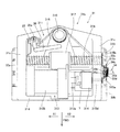
ここで、第1実施形態では、回動機構収納部31bの内部に収納されたスイベル軸310を回動するための回動機構部311は、電気により駆動するとともに、モータ軸313aを有するモータ313と、モータ313のモータ軸313aと接続されたロッククラッチ314と、ロッククラッチ314と接続されたギヤ部315とにより構成されている。また、回動機構部311は、さらに、モータ軸313aの回転がロッククラッチ314およびギヤ部315を介して伝達されるボールネジ316と、ボールネジ316上を移動可能に係合されたボールナット317と、ボールナット317が移動されるのに伴って、スイベル軸310を中心に回動するように構成された伝達プレート318とにより構成されている。なお、ロッククラッチ314は、本発明の「ロック部」の一例であり、ボールネジ316は、本発明の「推進機回動機構」の一例である。
Here, in 1st Embodiment, the
モータ313は、スイベルブラケット31の前壁部31d近傍の矢印X1方向側に配置されており、船外機本体30(図2参照)を回動させるための駆動力を発生させる機能を有する。また、モータ313は、ドライバ7と電気的に接続されている。ドライバ7は、ユーザが操舵部4(図1参照)を操舵した際に共通LANケーブル6により送信される信号に基づいてモータ313の駆動を制御するように構成されている。具体的には、ドライバ7は、操舵部4(図1参照)がA1方向(図1参照)に回転された場合には、モータ軸313aがA2方向に回転されるように制御するとともに、操舵部4(図1参照)がB1方向(図1参照)に回転された場合には、モータ軸313aがB2方向に回転されるように制御する。
The
また、モータ313は、モータ軸313aが船体2の幅方向(矢印X1方向および矢印X2方向)に延びるように配置されている。モータ軸313aは、モータ本体313bから矢印X2方向側(ロッククラッチ314側)に向かって突出するように構成されている。
Further, the
また、第1実施形態では、ロッククラッチ314は、モータ313により発生される駆動力を船外機本体30(図2参照)側に伝達するとともに、モータ313が駆動していない場合に、船外機本体30が左右方向に回動しないようにロックする機能を有する。このロッククラッチ314は、内部に図示しないラチェット機構などを有する機械的構造を有している。これにより、モータ軸313aが回転された場合に、モータ軸313aの回転をロッククラッチ314に接続されたギヤ部315に伝達することが可能である。その一方で、航行中などに、船外機本体30(図2参照)が左右方向に回動される力が付与されるのに伴ってギヤ部315に回転する力が付与された場合にも、ロッククラッチ314により、ギヤ部315が回転しようとすることをロックする。つまり、航行中、水から受ける反力が船外機本体30に対して左右方向に付与される場合にも、ロッククラッチ314により、操舵方向を維持するためにモータ313を駆動させる必要がない。すなわち、モータ313を常時駆動させる必要がない。
In the first embodiment, the
また、ギヤ部315は、図4および図5に示すように、ロッククラッチ314の下流側に設けられており、3つの平歯車が噛合することにより構成されている。また、ギヤ部315は、モータ313の駆動力を船外機本体30側に伝達する機能を有しており、モータ313の駆動力が入力される入力ギヤ315aと、モータ313の駆動力を下流側のボールネジ316に出力する出力ギヤ315bと、入力ギヤ315aから出力ギヤ315bに駆動力を伝達する中間ギヤ315cとにより構成されている。なお、中間ギヤ315cは、本発明の「ロック解除機構部」および「駆動力伝達部材」の一例である。これら入力ギヤ315a、出力ギヤ315bおよび中間ギヤ315cは、それぞれ、矢印X2方向側の側壁部31cの近傍に配置されている。具体的には、ギヤ部315は、図5に示すように、プレート部材33bの側壁部31c側に設けられた中空部33cに収納されている。
Further, as shown in FIGS. 4 and 5, the
また、入力ギヤ315aは、ロッククラッチ314の下流側(矢印X2方向側)から突出する軸部材315dと接続されており、軸部材315dと共に回転するように構成されている。また、出力ギヤ315bは、ボールネジ316と接続されており、ボールネジ316と一体的に回転するように構成されている。
The
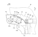
ここで、第1実施形態では、中間ギヤ315cは、入力ギヤ315aおよび出力ギヤ315bから離間可能に構成されている。具体的には、中間ギヤ315cには、モータ313が駆動していない場合に、船外機本体30を手動で左右方向(矢印X1方向および矢印X2方向)に回動させることが可能なようにロッククラッチ314によるロックを無効化する操作部34が設けられている。なお、操作部34は、本発明の「ロック解除機構部」の一例である。この操作部34は、中間ギヤ315cを入力ギヤ315aおよび出力ギヤ315bから離間することにより、ロッククラッチ314よりもモータ313の駆動力の下流側に設けられているギヤ部315の係合を解除するように構成されている。これにより、中間ギヤ315cが入力ギヤ315aおよび出力ギヤ315bから離間された場合に、ユーザが船外機本体30の外面部を手で把持して左右方向に回動させることが可能となる。
Here, in the first embodiment, the
また、第1実施形態では、操作部34は、図6に示すように、中間ギヤ315cの回転中心に嵌め込まれた軸受34aと、軸受34aに挿入された回転軸34bと、回転軸34bと同軸上で回転可能なネジ部34cを有する取っ手部34dとにより構成されている。この操作部34は、中間ギヤ315cを、軸受34aにより回転軸34bを中心に回転可能に支持する一方で、中間ギヤ315cを、軸受34aおよび回転軸34bを介して取っ手部34dと共に噛合方向に対して略垂直な方向(矢印X1方向および矢印X2方向)に移動するように構成されている。
In the first embodiment, as shown in FIG. 6, the
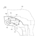
また、操作部34は、取っ手部34dのネジ部34cがプレート部材33bに設けられたネジ穴33dに螺合されることによりプレート部材33bに固定されている。プレート部材33bのネジ穴33dは、ギヤ部315の中間ギヤ315cが配置される部分に対応する位置に形成されており、取っ手部34dは、回転軸34bを中心にR1方向またはR2方向に回転されることにより、中間ギヤ315cを噛合方向に対して略垂直な方向(矢印X1方向および矢印X2方向)に移動可能に構成されている。つまり、操作部34は、図7に示すように、ユーザがスイベルブラケット31の外側から取っ手部34dを操作することにより、中間ギヤ315cの入力ギヤ315aおよび出力ギヤ315bに対する噛合を解除可能に構成されている。また、操作部34は、プレート部材33bに対して螺合されることにより固定されているので、噛合が解除された中間ギヤ315cを、再度、入力ギヤ315aおよび出力ギヤ315bに噛合することが可能である。
Further, the operating
ボールナット317は、図5に示すように、ボールネジ316が回転されるのに伴って矢印X1方向および矢印X2方向に移動されるように構成されている。つまり、モータ軸313aがA2方向に回転されるのに伴って、ギヤ部315を介してボールネジ316がA3方向に回転された場合に、ボールナット317は、矢印X1方向に移動されるように構成されている。その一方で、モータ軸313aがB2方向に回転されるのに伴って、ギヤ部315を介してボールネジ316がB3方向に回転された場合に、ボールナット317は、矢印X2方向に移動されるように構成されている。
As shown in FIG. 5, the
また、伝達プレート318は、ボールナット317と接続されている。また、伝達プレート318は、スイベル軸310と係合されている。これにより、伝達プレート318は、ボールナット317が矢印X1方向および矢印X2方向に移動されるのに伴って、スイベル軸310を中心に回動することが可能となる。その結果、スイベル軸310を回動させることが可能となる。
The
また、伝達プレート318の矢印X1方向側には、回動軸部35aの回動量を検知する回動センサ35が設けられている。回動センサ35は、リンク部材36により伝達プレート318と接続されており、リンク部材36は、伝達プレート318がスイベル軸310を中心に回動された際に移動するように構成されている。そして、リンク部材36が移動するのに伴って、回動センサ35の回動軸部35aは、回動されるように構成されている。このように回動軸部35aの回動量を検知することによって、ECU303(図1参照)などにより伝達プレート318の回動量を演算することが可能である。
A
次に、図1および図5〜図7を参照して、本発明の第1実施形態による船外機3のモータ313が駆動していない場合に、船外機本体30を手動で左右方向に回動させることが可能なようにロッククラッチ314によるロックを無効化する手順について説明する。
Next, referring to FIGS. 1 and 5 to 7, when the
図5および図6に示すように、ユーザが操作部34の取っ手部34dを図6のR1方向(図6参照)に手動で回転することにより、操作部34のネジ部34cがプレート部材33bのネジ穴33dに対してR1方向(図6参照)に回転される。これにより、図7に示すように、操作部34は、矢印X2方向に移動される。この際、取っ手部34dと共に軸受34aおよび回転軸34bが矢印X2方向に移動される。軸受34aは、中間ギヤ315cに嵌め込まれているので、中間ギヤ315cは、軸受34aと共に矢印X2方向(噛合解除方向)に移動される。これにより、中間ギヤ315cは、入力ギヤ315aおよび出力ギヤ315bに対して噛合が解除される。その結果、出力ギヤ315bよりも下流側は、ロッククラッチ314による拘束(ロック)がなくなるので、モータ313が駆動していない場合にも、船外機本体30(図1参照)のカウリング部300などの外面部をユーザの手で把持して左右方向に回動させることが可能となる。
As shown in FIGS. 5 and 6, when the user manually rotates the
次に、無効化されたロックを、再度、有効化する手順について説明する。 Next, a procedure for re-enabling a disabled lock will be described.
図6および図7に示すように、ユーザが操作部34の取っ手部34dを図6のR2方向(図6参照)に手動で回転することにより、操作部34のネジ部34cがプレート部材33bのネジ穴33dに対してR2方向(図6参照)に回転される。これにより、図5に示すように、操作部34は、矢印X1方向に移動される。この際、取っ手部34dと共に軸受34aおよび回転軸34bが矢印X1方向に移動される。軸受34aは、中間ギヤ315cに嵌め込まれているので、中間ギヤ315cは、軸受34aと共に矢印X1方向(噛合方向)に移動される。これにより、中間ギヤ315cは、入力ギヤ315aおよび出力ギヤ315bに対して再度噛合される。その結果、ロッククラッチ314による拘束(ロック)が解除されていた出力ギヤ315bよりも下流側は、再度拘束(ロック)されるので、船外機本体30(図1参照)が左右方向(矢印X1方向および矢印X2方向)に回動されることを抑制することが可能となる。
As shown in FIGS. 6 and 7, when the user manually rotates the
第1実施形態では、上記のように、モータ313により発生される駆動力を船外機本体30側に伝達するとともに、モータ313が駆動していない場合に、船外機本体30が左右方向に回動しないようにロックするロッククラッチ314を設けることによって、航行中、水により発生される反力が船外機本体30に対して左右方向に付与される場合にも、ロッククラッチ314により、操舵方向を維持するためにモータ313を駆動させる必要がない。これにより、船外機本体30を回動させるための駆動力を発生させるモータ313の負担が大きくなることを抑制することができる。また、ロッククラッチ314よりもモータ313の駆動力の下流側に、モータ313が駆動していない場合に、船外機本体30を手動で左右方向に回動させることが可能なようにロッククラッチ314によるロックを無効化する操作部34を設けることによって、ロッククラッチ314を設けたためにユーザが船外機本体30の外面部を手で把持して左右方向に回動させることが困難である場合にも、操作部34によりロッククラッチ314によるロックを無効化することにより、船外機本体30を左右方向に回動することができる。
In the first embodiment, as described above, the driving force generated by the
また、第1実施形態では、上記のように、中間ギヤ315cにおいて伝達される駆動力を切断可能に構成することによって、中間ギヤ315cにおいて、ロッククラッチ314によるロック力を切断することができる。これにより、ロッククラッチ314によるロックを中間ギヤ315cよりも下流側で無効化することができる。
In the first embodiment, as described above, the driving force transmitted in the
また、第1実施形態では、上記のように、ギヤ部315を、モータ313の駆動力が入力される入力ギヤ315aと、モータ313の駆動力を下流側に出力する出力ギヤ315bと、入力ギヤ315aから出力ギヤ315bに駆動力を伝達する中間ギヤ315cとにより構成するとともに、中間ギヤ315cを入力ギヤ315aおよび出力ギヤ315bから離間可能に構成することによって、中間ギヤ315cは、たとえば、ロッククラッチ314から突出する軸部材315dまたはボールネジ316などの、それ自体が駆動力を伝達する軸部を有さないので、入力ギヤ315aおよび出力ギヤ315bと比べて回転軸方向に移動させ易い。これにより、容易に、中間ギヤ315cの噛合を解除することができる。
In the first embodiment, as described above, the
また、第1実施形態では、上記のように、操作部34に、ユーザが直接的に操作可能な取っ手部34dを設けることによって、特別な工具などを使用せずに操作部34を操作することができる。
In the first embodiment, as described above, the
また、第1実施形態では、上記のように、操作部34を、ネジ部34cが回転されるのに伴って、中間ギヤ315cを噛合方向(矢印X1方向)、または、噛合解除方向(矢印X2方向)に移動するように構成することによって、ネジ部34cを回転することにより、容易に、中間ギヤ315cの噛合を解除することができるとともに、噛合解除された中間ギヤ315cを再度噛合することができる。
In the first embodiment, as described above, the
(第2実施形態)
以下、図8〜図10を参照して、本発明の第2実施形態による船外機の構成について詳細に説明する。この第2実施形態では、上記第1実施形態とは異なり、ロッククラッチ314によるロックが無効化されている場合に、船外機本体80を容易に手動で左右方向に回動させることが可能な回転部材81を設けた例について説明する。
(Second Embodiment)
Hereinafter, the configuration of the outboard motor according to the second embodiment of the present invention will be described in detail with reference to FIGS. In the second embodiment, unlike the first embodiment, when the lock by the
第2実施形態では、図8に示すように、ボールネジ816の矢印X1方向側の端部近傍には、回転部材81が設けられている。この回転部材81は、モータ313が駆動していない場合で、かつ、ロッククラッチ314によるロックが無効化されている場合に、船外機本体80(図9参照)を容易に手動で左右方向に回動させるために設けられている。なお、船外機本体80は、本発明の「推進機本体」の一例である。
In the second embodiment, as shown in FIG. 8, a rotating
具体的には、第2実施形態では、回転部材81は、ボールネジ816の長手方向(矢印X1方向)の端部に設けられているとともに、ボールネジ816と略同軸上で回転可能に構成されている。つまり、ボールネジ816は、回転部材81が回転されるのに伴って回転部材81と一体的に回転されるように構成されている。なお、回転部材81は、本発明の「手動操舵部」の一例である。また、回転部材81の矢印X1方向側の面には、六角レンチ82(図10参照)を係合することが可能な六角穴81aが形成されている。これにより、ユーザが六角レンチ82(図10参照)を六角穴81aに係合させるとともに、六角レンチ82を回転させることによって、回転部材81を回転させることが可能となる。つまり、回転部材81は、ボールネジ816を直接的に回転させることが可能なように構成されている。なお、六角レンチ82は、本発明の「所定の工具」の一例である。
Specifically, in the second embodiment, the rotating
また、スイベルブラケット83の矢印X1方向側の側壁部83cおよびプレート部材84aの回転部材81に対応する部分には、開口部83eが形成されている。開口部83eは、六角レンチ82(図10参照)をスイベルブラケット83の外部からスイベルブラケット83の内部の回転部材81の六角穴81aにアクセスするために設けられている。また、開口部83eは、図9に示すように、六角レンチ82(図10参照)を用いて回転部材81を回転させる場合以外の場合に、開口部83eに対して着脱可能な蓋部材85を用いることによって、塞ぐことが可能なように構成されている。なお、スイベルブラケット83およびプレート部材84aは、本発明の「スイベル部」の一例である。
Further, an
具体的には、図8に示すように、開口部83eは、内周面にネジ加工が施されたネジ部83fと、ネジ部83fよりも小さな径を有するとともに、ネジ部83fの矢印X2方向側に隣接する穴部83gと、ネジ部83fと穴部83gとの間の段差部83hとを有している。また、蓋部材85は、開口部83eのネジ部83fと螺合可能に形成されたネジ部85aと、ユーザが手により摘むことが可能な摘み部85bとにより主に構成されている。つまり、蓋部材85は、ユーザが摘み部85bを摘むとともに開口部83eのネジ部83fに螺合することにより、開口部83eを塞ぐことが可能なように構成されている。
Specifically, as shown in FIG. 8, the
また、開口部83eの段差部83hには、Oリング86が設けられている。このOリング86は、蓋部材85がネジ部83fに係合された際に、蓋部材85の底部85cと段差部83hとの間に挟み込まれるように配置されている。これにより、六角レンチ82(図10参照)を用いて回転部材81を回転させる場合以外の場合に、スイベルブラケット83の内部を密閉することが可能となる。
Further, an O-
なお、第2実施形態のその他の構造は、上記第1実施形態と同様である。 The remaining structure of the second embodiment is the same as that of the first embodiment.
次に、図8および図10を参照して、本発明の第2実施形態による船外機本体80のモータ313が駆動していない場合で、かつ、ロッククラッチ314によるロックが無効化されている場合に、ユーザにより船外機本体80を左右方向に回動させる動作について説明する。ここで、船外機本体80を矢印X1方向に回動させる動作を説明する。
Next, referring to FIGS. 8 and 10, when the
図8に示すように、蓋部材85が開口部83eから取り外された状態で、六角レンチ82(図10参照)を開口部83eに挿入するとともに、回転部材81の六角穴81aに係合させる。そして、六角レンチ82をA3方向に回転することにより、回転部材81を回転させる。これにより、回転部材81と共にボールネジ816は、A3方向に回転される。この際、ギヤ部315の中間ギヤ315cの噛合が解除されているので、中間ギヤ315cよりも下流側の出力ギヤ315bが受けていたロッククラッチ314によるロックは、無効化されている。つまり、出力ギヤ315bが接続されているボールネジ816のロックも無効化されているので、ボールネジ816を容易に回転させることが可能である。
As shown in FIG. 8, with the
そして、ボールネジ816がA3方向に回転されるのに伴って、ボールナット317は、矢印X1方向に移動される。そして、ボールナット317が矢印X1方向に移動されるのに伴って、伝達プレート318は、スイベル軸310を中心に矢印X1方向に回動される。これにより、伝達プレート318と係合されているスイベル軸310は、A4方向に回動される。その結果、船外機本体80は、矢印X1方向に回動される。
Then, as the
なお、第2実施形態のその他の構造および動作は、上記第1実施形態と同様である。 The remaining structure and operation of the second embodiment are the same as those of the first embodiment.
第2実施形態では、上記のように、中間ギヤ315cの噛合が解除されることによりロッククラッチ314のロックを無効化している場合に、ボールネジ816を手動で回転させる回転部材81を設けることによって、ボールネジ816を回転させることにより、船外機本体80を回動させることができるので、ユーザが船外機本体80の外面部を手で把持して左右方向に回動させる場合と比べて、容易に、船外機本体80を左右方向に回動することができる。
In the second embodiment, as described above, when the lock of the
また、第2実施形態では、上記のように、回転部材81を、ボールネジ816の長手方向(矢印X1方向)の端部に設けるとともに、ユーザが六角レンチ82を使用することにより直接的にボールネジ816を回転させることが可能なように構成することによって、六角レンチ82により、容易に、ボールネジ816を回転させることができる。
In the second embodiment, as described above, the rotating
(第3実施形態)
以下、図11〜図13を参照して、本発明の第3実施形態による船外機の構成について詳細に説明する。この第3実施形態では、上記第1実施形態とは異なり、ロッククラッチ314によるロックを無効化するために、駆動力を伝達するためのピン部材906を取り外す例について説明する。
(Third embodiment)
Hereinafter, the configuration of the outboard motor according to the third embodiment of the present invention will be described in detail with reference to FIGS. In the third embodiment, unlike the first embodiment, an example in which the
図11および図12に示すように、第3実施形態では、スイベル軸910は、上下方向(Z方向)に延びるように配置されている。また、スイベル軸910の上部には、スイベル軸910と船外機本体90とを連結する連結部材905が配置されている。なお、船外機本体90は、本発明の「推進機本体」の一例である。連結部材905は、スイベル軸910が回動するのに伴って、スイベル軸310と共に回動するように構成されている。具体的には、図12および図13に示すように、スイベル軸910および連結部材905には、それぞれ、貫通穴910a(図13参照)および905a(図13参照)が形成されており、貫通穴910aおよび905aには、ピン部材906が挿入されている。なお、ピン部材906は、本発明の「ロック解除機構部」および「駆動力伝達部材」の一例である。また、ピン部材906の両端部近傍の外周部には、係合溝906aが形成されており、この係合溝906aには、それぞれ、スナップリング(Cリング)907が係合されている。これらスナップリング907は、ピン部材906が貫通穴910aおよび905aから抜け落ちることを抑制する機能を有する。
As shown in FIGS. 11 and 12, in the third embodiment, the
また、スイベルブラケット91の回動機構収納部91b(図12参照)の開口した上部は、図11に示すように、開口全面を覆うことが可能なカバー部材912を取付可能に構成されている。つまり、回動機構収納部91bは、内部を密閉することが可能なように構成されている。なお、スイベル軸910の上部は、カバー部材912よりも上側に突出している。また、スイベルブラケット91は、本発明の「スイベル部」の一例である。
Moreover, as shown in FIG. 11, the upper part which the rotation
また、ギヤ部915は、図11および図13に示すように、ロッククラッチ314の下流側に設けられており、3つの平歯車が噛合することにより構成されている。ギヤ部915は、モータ313の駆動力が入力される入力ギヤ915aと、モータ313の駆動力を下流側のボールネジ316に出力する出力ギヤ915bと、入力ギヤ915aから出力ギヤ915bに駆動力を伝達する中間ギヤ915cとにより構成されている。また、入力ギヤ915aは、図13に示すように、ロッククラッチ314の下流側(矢印X2方向側)から突出する軸部材915dと接続されており、軸部材915dと共に回転するように構成されている。また、出力ギヤ915bは、ボールネジ316と接続されており、ボールネジ316と一体的に回転するように構成されている。
As shown in FIGS. 11 and 13, the
また、第3実施形態では、スイベルブラケット91の側壁部91cには、ギヤ部915の矢印X2方向側を覆うようにプレート部材93bが取り付けられている。
In the third embodiment, a
図14は、本発明の第3実施形態による船外機のピン部材を取り外す手順を説明するための平面図である。次に、図11および図14を参照して、本発明の第3実施形態による船外機のモータ313が駆動していない場合に、船外機本体90を手動で左右方向に回動させることが可能なようにロッククラッチ314によるロックを無効化する手順について説明する。
FIG. 14 is a plan view for explaining the procedure for removing the pin member of the outboard motor according to the third embodiment of the present invention. Next, referring to FIG. 11 and FIG. 14, when the
図14に示すように、図示しないマイナスドライバーなどにより、ピン部材906に係合されている少なくとも1つのスナップリング907を取り外す。そして、ピン部材906の取り外されたスナップリング907側の部分をマイナスドライバー(図示せず)などにより押圧する。これにより、ピン部材906は、貫通穴910aおよび905aから押し出される。その結果、連結部材905をスイベル軸910の上部に対して自由に回動させることが可能となる。つまり、連結部材905は、ロッククラッチ314によるロックが無効化されるので、モータ313が駆動していない場合にも、船外機本体90(図11参照)の外面部をユーザの手で把持して左右方向に回動させることが可能となる。
As shown in FIG. 14, at least one
なお、第3実施形態のその他の構造および動作は、上記第1実施形態と同様である。 Other structures and operations of the third embodiment are the same as those of the first embodiment.
第3実施形態では、上記のように、連結部材905およびスイベル軸910を、ロッククラッチ314によるロックを無効化する際に、連結部材905とスイベル軸910とを係合するピン部材906を取り外しすることが可能なように構成することによって、連結部材905とスイベル軸910とを係合するピン部材906を取り外すことにより、容易に、ロッククラッチ314によるロックを無効化することができる。
In the third embodiment, as described above, the
(第4実施形態)
以下、図15〜図18を参照して、本発明の第4実施形態による船外機の構成について詳細に説明する。この第4実施形態では、上記第1および第2実施形態とは異なり、ロッククラッチ314からボールネジ316への駆動力の伝達をプーリ372、ベルト373およびプーリ374により行うとともに、プーリ372をロッククラッチ314から離間可能に構成した例について説明する。
(Fourth embodiment)
Hereinafter, the configuration of the outboard motor according to the fourth embodiment of the present invention will be described in detail with reference to FIGS. In the fourth embodiment, unlike the first and second embodiments, the driving force is transmitted from the
ここで、第4実施形態では、図15および図16に示すように、回動機構部371(図16参照)は、ロッククラッチ314(図16参照)の下流側の出力軸314a(図16参照)と着脱可能に係合されたプーリ372と、プーリ372に噛合され、下流側に駆動力を伝達するベルト373と、プーリ372の後方側でベルト373と噛合されたプーリ374とにより構成されている。なお、プーリ372は、本発明の「ロック解除機構部」および「駆動力伝達部材」の一例である。
Here, in the fourth embodiment, as shown in FIGS. 15 and 16, the rotation mechanism 371 (see FIG. 16) has an
プーリ372は、図16および図17に示すように、ロッククラッチ314の下流側の出力軸314aと係合されている場合には、出力軸314aと共に回転するように構成されている。そして、図16に示すように、プーリ372の回転に伴って、ベルト373は、駆動されるように構成されているとともに、ベルト373の駆動に伴って、プーリ374は、回転されるように構成されている。プーリ374は、ボールネジ316と共に回転可能にボールネジ316に取り付けられているので、プーリ374が回転するのに伴って、ボールネジ316を回転させることが可能となる。
As shown in FIGS. 16 and 17, the
ここで、第4実施形態では、図17に示すように、プーリ372には、モータ313が駆動していない場合に、船外機本体370(図15参照)を手動で左右方向(矢印X1方向および矢印X2方向)に回動させることが可能なようにロッククラッチ314によるロックを無効化する操作部375が設けられている。なお、操作部375は、本発明の「ロック解除機構部」の一例である。この操作部375は、プーリ372をロッククラッチ314の下流側の出力軸314aから離間させることが可能なように構成されている。これにより、プーリ372がロッククラッチ314の下流側の出力軸314aから離間された場合に、ユーザが船外機本体370の外面部を手で把持して左右方向に回動させることが可能となる。
Here, in the fourth embodiment, as shown in FIG. 17, when the
また、第4実施形態では、操作部375は、図17および図18に示すように、プレート部材376のネジ穴部376aと螺合可能に構成された蓋部375aと、外周部が蓋部375aに嵌め込まれた軸受375bと、軸受375bの内周部に嵌め込まれるとともにプーリ372の回転中心と接続された軸部375cとにより構成されている。蓋部375aは、プレート部材376のネジ穴部376aに対して回転させることにより、矢印X1方向および矢印X2方向に移動可能に構成されている。蓋部375aが矢印X1方向および矢印X2方向に移動されるのに伴って、操作部375は、軸部375cを介してプーリ372を出力軸314aと係合する方向(矢印X1方向)および離間する方向(矢印X2方向)に移動可能に構成されている。また、軸受375bは、プーリ372が回転された際に、プーリ372および軸部375cの回転が蓋部375aに伝達されないようにする機能を有する。
In the fourth embodiment, as shown in FIGS. 17 and 18, the
また、操作部375の蓋部375aには、プレート部材376の外面部376bと面接触可能なフランジ部375dが設けられている。このフランジ部375dは、プレート部材376の外面部376bと面接触された際に、スイベルブラケット31の内部に水が浸入するのを抑制する機能を有する。
Further, a
第4実施形態では、上記のように、ロッククラッチ314の下流側の出力軸314aに着脱可能に係合するプーリ372と、プーリ372と噛合するとともに、下流側に駆動力を伝達するベルト373とを設けるとともに、プーリ372はロッククラッチ314の下流側の出力軸314aから離間することが可能なように構成されている。これにより、プーリ372をロッククラッチ314の下流側の出力軸314aから離間することにより、容易に、ロッククラッチ314によるロックを無効化することができる。
In the fourth embodiment, as described above, the
なお、今回開示された実施形態は、すべての点で例示であって制限的なものではないと考えられるべきである。本発明の範囲は、上記した実施形態の説明ではなく特許請求の範囲によって示され、さらに特許請求の範囲と均等の意味および範囲内でのすべての変更が含まれる。 The embodiment disclosed this time should be considered as illustrative in all points and not restrictive. The scope of the present invention is shown not by the above description of the embodiments but by the scope of claims for patent, and further includes all modifications within the meaning and scope equivalent to the scope of claims for patent.
たとえば、上記第1〜第3実施形態では、本発明のロック解除機構部に、中間ギヤやピン部材を適用した例について示したが、本発明はこれに限らず、たとえば、ロッククラッチと入力ギヤとの間にロッククラッチと入力ギヤとを接続するカップリングを設けるとともに、ロッククラッチによるロックを無効化する際に、カップリングを切り離す構成を設ける構造を、本発明のロック解除機構部に適用するなど、ロッククラッチよりも下流側に設けられているならば、上記第1〜第3実施形態による構成でなくてもよい。 For example, in the first to third embodiments, an example in which an intermediate gear or a pin member is applied to the unlocking mechanism of the present invention has been described. However, the present invention is not limited thereto, and for example, a lock clutch and an input gear are used. A structure for providing a coupling for connecting the lock clutch and the input gear between the lock clutch and the structure for separating the coupling when the lock by the lock clutch is invalidated is applied to the lock release mechanism portion of the present invention. If it is provided downstream from the lock clutch, the configuration according to the first to third embodiments may not be required.
また、上記第2実施形態では、回転部材を、六角レンチにより回転させるように構成した例について示したが、本発明はこれに限らず、たとえば、マイナスドライバーなど、六角レンチ以外の工具により回転させるように構成してもよい。また、工具などを使用せずに、たとえば、ユーザの手により直接的に回転部材を回転することが可能なダイヤルレバーを回転部材に設けるようにしてもよい。 Moreover, in the said 2nd Embodiment, although the rotating member was shown about the example comprised so that it might rotate with a hexagon wrench, this invention is not limited to this, For example, it rotates with tools other than a hexagon wrench, such as a flat-blade screwdriver. You may comprise as follows. Moreover, you may make it provide a dial lever which can rotate a rotation member directly by a user's hand, for example, without using a tool etc. in a rotation member.
また、上記第1〜第3実施形態では、ロック部の一例として、機械的構造を有するロッククラッチを適用した例について示したが、本発明はこれに限らず、たとえば、電気的に作動する電磁クラッチなど、機械的構造を有するロッククラッチ以外のロック機構を適用してもよい。 Moreover, in the said 1st-3rd embodiment, although the example which applied the lock clutch which has a mechanical structure as an example of a lock | rock part was shown, this invention is not limited to this, For example, the electromagnetic which act | operates electrically A lock mechanism other than a lock clutch having a mechanical structure such as a clutch may be applied.
また、上記第1および第2実施形態では、中間ギヤの噛合を解除可能に構成した例について示したが、本発明はこれに限らず、たとえば、入力ギヤまたは出力ギヤなど、駆動力を伝達するギヤであるならば、中間ギヤ以外のギヤの噛合を解除可能に構成してもよい。 In the first and second embodiments, the example in which the meshing of the intermediate gear can be released has been described. However, the present invention is not limited to this, and the driving force is transmitted to the input gear or the output gear, for example. If it is a gear, you may comprise so that engagement of gears other than an intermediate gear can be cancelled | released.
また、上記第1〜第3実施形態では、本発明を、船外機を2機設置した船舶に適用した例について示したが、本発明はこれに限らず、本発明を、船外機を1機のみ設置した船舶、または、船外機を3機以上設置した船舶に適用してもよい。 In the first to third embodiments, the present invention has been described with reference to an example in which the present invention is applied to a ship provided with two outboard motors. However, the present invention is not limited thereto, and the present invention is not limited to an outboard motor. You may apply to the ship which installed only one machine, or the ship which installed three or more outboard motors.
また、上記第4実施形態では、図16に示すように、ロッククラッチからボールネジへの駆動力の伝達をプーリ372、ベルト373およびプーリ374により行うとともに、プーリ372をロッククラッチから離間可能に構成した例について示したが、本発明はこれに限らず、図19に示すように、ロッククラッチ314からボールネジ316への駆動力の伝達をスプロケット382、チェーン383およびスプロケット384により行うとともに、プーリ372をロッククラッチ314から離間可能に構成してもよい。
In the fourth embodiment, as shown in FIG. 16, the driving force is transmitted from the lock clutch to the ball screw by the
上記第4実施形態の変形例では、回動機構部381は、ロッククラッチ314の下流側の出力軸314aと着脱可能に係合されたスプロケット382と、スプロケット382に噛合され、下流側に駆動力を伝達するチェーン383と、スプロケット382の後方側でチェーン383と噛合されたスプロケット384とにより構成されている。なお、スプロケット382は、本発明の「ロック解除機構部」および「駆動力伝達部材」の一例である。
In the modified example of the fourth embodiment, the
スプロケット382には、モータ313が駆動していない場合に、船外機本体(図示せず)を手動で左右方向(矢印X1方向および矢印X2方向)に回動させることが可能なようにロッククラッチ314によるロックを無効化する操作部385が設けられている。なお、操作部385は、本発明の「ロック解除機構部」の一例である。この操作部385は、スプロケット382をロッククラッチ314の下流側の出力軸314aから離間させることが可能なように構成されている。これにより、スプロケット382がロッククラッチ314の下流側の出力軸314aから離間された場合に、ユーザが船外機本体(図示せず)の外面部を手で把持して左右方向に回動させることが可能となる。また、操作部385の蓋部385aが矢印X1方向および矢印X2方向に移動されるのに伴って、操作部385は、軸部385cを介してスプロケット382を出力軸314aと係合する方向(矢印X1方向)および離間する方向(矢印X2方向)に移動可能に構成されている。
The
2 船体
3 船外機(舶用推進機)
30、80、90、370 船外機本体(推進機本体)
31、83、91 スイベルブラケット(スイベル部)
34、375、385 操作部(ロック解除機構部)
34c ネジ部
34d 取っ手部
81 回転部材(手動操舵部)
82 六角レンチ(所定の工具)
83e 開口部
85 蓋部材
313 モータ
314 ロッククラッチ(ロック部)
315 ギヤ部
315a 入力ギヤ
315b 出力ギヤ
315c 中間ギヤ(ロック解除機構部、駆動力伝達部材)
316 ボールネジ(推進機回動機構)
372 プーリ(ロック解除機構部、駆動力伝達部材)
373 ベルト
382 スプロケット(ロック解除機構部、駆動力伝達部材)
383 チェーン
906 ピン部材(ロック解除機構部、駆動力伝達部材)
910 スイベル軸(ロック解除機構部)
905 連結部材
2 Hull 3 Outboard motor (marine propulsion unit)
30, 80, 90, 370 Outboard motor body (propulsion body)
31, 83, 91 Swivel bracket (swivel part)
34, 375, 385 Operation part (lock release mechanism part)
82 Hexagon wrench (specified tool)
83e opening 85
315
316 Ball screw (propulsion unit rotation mechanism)
372 pulley (lock release mechanism, drive force transmission member)
373
383
910 Swivel shaft (lock release mechanism)
905 connecting member
Claims (14)
船体に対して前記推進機本体を左右方向に回動可能に取り付けるスイベル部と、
前記スイベル部に設けられ、前記推進機本体を回動させるための駆動力を発生させるモータと、
前記モータにより発生される駆動力を前記推進機本体側に伝達するとともに、前記推進機本体が左右方向に回動しないようにロックするロック部と、
前記ロック部よりも前記モータの駆動力の下流側に設けられ、前記ロック部によるロックを無効化するロック解除機構部とを備える、舶用推進機。 A propeller body,
A swivel part for attaching the propulsion unit main body to the hull so as to be turnable in the left-right direction;
A motor that is provided in the swivel unit and generates a driving force for rotating the propulsion unit main body;
A lock unit that transmits the driving force generated by the motor to the propulsion unit main body side and locks the propulsion unit main body to prevent rotation in the left-right direction;
A marine propulsion device provided with a lock release mechanism portion that is provided on the downstream side of the driving force of the motor from the lock portion and invalidates the lock by the lock portion.
前記ロック解除機構部は、前記少なくとも1つのギヤの噛合を解除可能に構成されている、請求項2に記載の舶用推進機。 The predetermined driving force transmission member is provided on the downstream side of the lock portion, and has at least one gear of gear portions that mesh with a plurality of gears,
The marine propulsion device according to claim 2, wherein the lock release mechanism is configured to be able to release the engagement of the at least one gear.
前記ロック解除機構部は、前記中間ギヤを前記入力ギヤおよび前記出力ギヤの少なくとも一方から離間可能に構成されている、請求項3に記載の舶用推進機。 The gear portion includes an input gear to which the driving force of the motor is input, an output gear that outputs the driving force of the motor downstream, and an intermediate gear that transmits the driving force from the input gear to the output gear. Have
The marine propulsion device according to claim 3, wherein the unlocking mechanism portion is configured to be able to separate the intermediate gear from at least one of the input gear and the output gear.
前記ロック解除機構部が前記ロック部のロックを無効化している場合に、前記推進機回動機構を手動で回転させる手動操舵部とをさらに備える、請求項1〜7のいずれか1項に記載の舶用推進機。 A propulsion unit rotating mechanism that is provided on the downstream side of the unlocking mechanism unit and rotates the propulsion unit main body with rotation;
8. The manual steering unit according to claim 1, further comprising: a manual steering unit that manually rotates the propulsion unit rotation mechanism when the lock release mechanism unit invalidates the lock of the lock unit. Marine propulsion machine.
前記スイベル部の開口部を塞ぐ着脱可能な蓋部材をさらに備える、請求項9に記載の舶用推進機。 The swivel part has an opening part into which the predetermined tool can be inserted in a part corresponding to the manual steering part,
The marine propulsion device according to claim 9, further comprising a detachable lid member that closes the opening of the swivel portion.
前記スイベル軸と前記推進機本体とを連結する連結部材とをさらに備え、
前記ロック解除機構部の所定の駆動力伝達部材は、前記スイベル軸が回動するのに伴って前記連結部材が回動されるように前記スイベル軸と前記連結部材とを係合可能なピン部材を有しており、前記ロック部によるロックを無効化する際に、前記連結部材と前記スイベル軸とを係合する前記ピン部材を取り外しすることが可能なように構成されている、請求項2に記載の舶用推進機。 A swivel shaft that rotates the propeller body as the motor is driven;
A connecting member that connects the swivel shaft and the propulsion unit main body;
The predetermined driving force transmitting member of the unlocking mechanism portion is a pin member that can engage the swivel shaft and the connecting member so that the connecting member is rotated as the swivel shaft is rotated. The pin member that engages the connecting member and the swivel shaft can be removed when the lock by the lock portion is invalidated. The marine propulsion device described in 1.
前記ロック解除機構部は、前記プーリを前記ロック部の下流側から離間することが可能なように構成されている、請求項2に記載の舶用推進機。 The predetermined driving force transmission member includes a pulley that is detachably engaged with the downstream side of the lock portion, and a belt that meshes with the pulley and transmits a driving force to the downstream side,
The marine propulsion device according to claim 2, wherein the lock release mechanism portion is configured to be able to separate the pulley from a downstream side of the lock portion.
前記ロック解除機構部は、前記スプロケットを前記ロック部の下流側から離間することが可能なように構成されている、請求項2に記載の舶用推進機。 The predetermined driving force transmission member has a sprocket that is detachably engaged with the downstream side of the lock portion, and a chain that meshes with the sprocket and transmits the driving force to the downstream side,
The marine propulsion device according to claim 2, wherein the unlocking mechanism portion is configured to be able to separate the sprocket from a downstream side of the lock portion.
Priority Applications (2)
| Application Number | Priority Date | Filing Date | Title |
|---|---|---|---|
| JP2009005917A JP5123219B2 (en) | 2009-01-14 | 2009-01-14 | Marine propulsion device |
| US12/685,020 US8246400B2 (en) | 2009-01-14 | 2010-01-11 | Steering apparatus for propulsion device and propulsion device |
Applications Claiming Priority (1)
| Application Number | Priority Date | Filing Date | Title |
|---|---|---|---|
| JP2009005917A JP5123219B2 (en) | 2009-01-14 | 2009-01-14 | Marine propulsion device |
Publications (2)
| Publication Number | Publication Date |
|---|---|
| JP2010162999A JP2010162999A (en) | 2010-07-29 |
| JP5123219B2 true JP5123219B2 (en) | 2013-01-23 |
Family
ID=42596574
Family Applications (1)
| Application Number | Title | Priority Date | Filing Date |
|---|---|---|---|
| JP2009005917A Active JP5123219B2 (en) | 2009-01-14 | 2009-01-14 | Marine propulsion device |
Country Status (1)
| Country | Link |
|---|---|
| JP (1) | JP5123219B2 (en) |
Families Citing this family (1)
| Publication number | Priority date | Publication date | Assignee | Title |
|---|---|---|---|---|
| US9139275B2 (en) | 2012-03-22 | 2015-09-22 | Yamaha Hatsudoki Kabushiki Kaisha | Suspension device for outboard motor and vessel propulsion apparatus |
Family Cites Families (3)
| Publication number | Priority date | Publication date | Assignee | Title |
|---|---|---|---|---|
| JP2003056603A (en) * | 2001-08-09 | 2003-02-26 | Ntn Corp | Electric motor unit |
| JP2004231109A (en) * | 2003-01-31 | 2004-08-19 | Kayaba Ind Co Ltd | Power steering device for boat with outboard motor |
| JP4664691B2 (en) * | 2005-01-21 | 2011-04-06 | 本田技研工業株式会社 | Outboard motor steering system |
-
2009
- 2009-01-14 JP JP2009005917A patent/JP5123219B2/en active Active
Also Published As
| Publication number | Publication date |
|---|---|
| JP2010162999A (en) | 2010-07-29 |
Similar Documents
| Publication | Publication Date | Title |
|---|---|---|
| US9764813B1 (en) | Tillers, tiller systems and methods for controlling outboard motors with tillers | |
| US9789945B1 (en) | Angularly adjustable tillers for outboard motors | |
| WO2014034324A1 (en) | Operating device for electric outboard motor | |
| US9783278B1 (en) | Tiller having removable top cover | |
| US10246173B1 (en) | Tillers for outboard motors having neutral shift interlock mechanism | |
| EP3354558B1 (en) | Side-mount type engine control apparatus | |
| WO2016091191A1 (en) | Outboard motor fixing device, and outboard motor using same | |
| JP2004001638A (en) | Shift change device for outboard engine | |
| JP2015166225A (en) | Control lever and remote control device | |
| WO2010123380A3 (en) | Underwater vessel with improved propulsion and handling | |
| JP5123219B2 (en) | Marine propulsion device | |
| JP5341530B2 (en) | Marine propulsion device | |
| JP2002137795A (en) | Remote control device for small ship | |
| US7217167B2 (en) | Outboard motor shift device | |
| JP2014237399A (en) | Remote control device | |
| JP2006290198A (en) | Outboard motor | |
| JP4098667B2 (en) | Electric bending endoscope | |
| US8246400B2 (en) | Steering apparatus for propulsion device and propulsion device | |
| JP6413909B2 (en) | Outboard motor | |
| JP3904479B2 (en) | Outboard motor steering system | |
| JP2006341676A (en) | Remote controller of outboard motor | |
| JP2006205788A (en) | Handle structure of outboard motor | |
| JP7263417B2 (en) | Outboard motor | |
| US20180141632A1 (en) | Motor-Boat Control System | |
| JP5886038B2 (en) | Operating device |
Legal Events
| Date | Code | Title | Description |
|---|---|---|---|
| A621 | Written request for application examination |
Free format text: JAPANESE INTERMEDIATE CODE: A621 Effective date: 20111012 |
|
| A977 | Report on retrieval |
Free format text: JAPANESE INTERMEDIATE CODE: A971007 Effective date: 20121018 |
|
| TRDD | Decision of grant or rejection written | ||
| A01 | Written decision to grant a patent or to grant a registration (utility model) |
Free format text: JAPANESE INTERMEDIATE CODE: A01 Effective date: 20121023 |
|
| A01 | Written decision to grant a patent or to grant a registration (utility model) |
Free format text: JAPANESE INTERMEDIATE CODE: A01 |
|
| A61 | First payment of annual fees (during grant procedure) |
Free format text: JAPANESE INTERMEDIATE CODE: A61 Effective date: 20121025 |
|
| FPAY | Renewal fee payment (event date is renewal date of database) |
Free format text: PAYMENT UNTIL: 20151102 Year of fee payment: 3 |
|
| R150 | Certificate of patent or registration of utility model |
Ref document number: 5123219 Country of ref document: JP Free format text: JAPANESE INTERMEDIATE CODE: R150 Free format text: JAPANESE INTERMEDIATE CODE: R150 |
|
| R250 | Receipt of annual fees |
Free format text: JAPANESE INTERMEDIATE CODE: R250 |
|
| R250 | Receipt of annual fees |
Free format text: JAPANESE INTERMEDIATE CODE: R250 |
|
| R250 | Receipt of annual fees |
Free format text: JAPANESE INTERMEDIATE CODE: R250 |
|
| R250 | Receipt of annual fees |
Free format text: JAPANESE INTERMEDIATE CODE: R250 |
|
| R250 | Receipt of annual fees |
Free format text: JAPANESE INTERMEDIATE CODE: R250 |
|
| R250 | Receipt of annual fees |
Free format text: JAPANESE INTERMEDIATE CODE: R250 |
|
| R250 | Receipt of annual fees |
Free format text: JAPANESE INTERMEDIATE CODE: R250 |
|
| R250 | Receipt of annual fees |
Free format text: JAPANESE INTERMEDIATE CODE: R250 |
|
| R250 | Receipt of annual fees |
Free format text: JAPANESE INTERMEDIATE CODE: R250 |